operating instructions - Rusch-Pumpen Fabrik GmbH
operating instructions - Rusch-Pumpen Fabrik GmbH
operating instructions - Rusch-Pumpen Fabrik GmbH

Sie wollen auch ein ePaper? Erhöhen Sie die Reichweite Ihrer Titel.
YUMPU macht aus Druck-PDFs automatisch weboptimierte ePaper, die Google liebt.
<strong>Rusch</strong> – <strong>Pumpen</strong> <strong>Fabrik</strong> <strong>GmbH</strong><br />
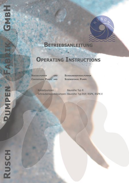
BETRIEBSANLEITUNG<br />
-<br />
OPERATING INSTRUCTIONS<br />
KREISELPUMPEN UND SCHRAUBENSPINDELPUMPEN<br />
CENTRIFUGAL PUMPS AND SCREWSPINDEL PUMPS<br />
Kreiselpumpen : Baureihe Typ R<br />
Schraubenspindelpumpen: Baureihe Typ RSP, RSPK, RSPK-V
OPERATING INSTRUCTIONS<br />
BETRIEBSANWEISUNG<br />
Kreiselpumpen: Baureihe R, RS, RN<br />
Schraubenspindelpumpen: Baureihe RSP; RSPK; RSPD; RSPKV<br />
INHALTSVERZEICHNIS<br />
1.0 ALLGEMEINES 5<br />
1.1 VORWORT 5<br />
1.2 GARANTIE 5<br />
1.3 PRÜFUNG 6<br />
2.0 BESCHREIBUNG 6<br />
2.1. EINSATZGEBIET FÜR KREISELPUMPEN UND SCHRAUBENSPINDELPUMPEN 6<br />
2.1.1. SELBSTANSAUGUNG - KREISELPUMPE 6<br />
2.1.2 NORMALANSAUGUNG - KREISELPUMPE 6<br />
2.2.1 SELBSTANSAUGUNG - SCHRAUBENSPINDELPUMPE 7<br />
2.3.1 AUFBAU-KREISELPUMPE 7<br />
2.3.2 AUFBAU-SCHRAUBENSPINDELPUMPE 7<br />
3.0 TRANSPORT UND MONTAGE 8<br />
3.1 TRANSPORT 8<br />
3.2 AUSRICHTUNG DER GRUNDPLATTE BZW. GRUNDRAHMENS AUF<br />
DEM FUNDAMENT 10<br />
3.3 ELEKTRISCHER ANSCHLUSS 11<br />
3.4 AUSRICHTEN DER KUPPLUNG 11<br />
3.5 ROHRLEITUNGEN 13<br />
4.0 BETRIEB DER PUMPE 14<br />
4.1.1 INBETRIEBNAHME EINER KREISELPUMPE 14<br />
4.1.2 INBETRIEBNAHME EINER SCHRAUBENSPINDELPUMPE 15<br />
4.2.1 STILLSETZEN DER MASCHINE (KREISELPUMPE) 16<br />
4.2 STILLSETZEN DER MASCHINE (SCHRAUBENSPINDELPUMPE) 17<br />
4.3 LAUFENDE BETRIEBSKONTROLLE UND WARTUNG 17<br />
4.3.1 ALLGEMEINE RICHTLINIEN 17<br />
4.3.2 GLEITRINGDICHTUNG 19<br />
4.3.3 FILTERVORSCHRIFTEN FÜR SCHRAUBENSPINDELPUMPEN 20<br />
4.3.4 KONSERVIERUNG UND EINLAGERUNG 20<br />
4.3.5 MÖGLICHE BETRIEBSSTÖRUNGEN UND IHRE URSACHEN 21<br />
RUSCH PUMPENFABRIK GMBH 3
OPERATING INSTRUCTIONS<br />
Centrifugal Pump: Baureihe R, RS, RN<br />
Screwspindel Pump: Baureihe RSP; RSPK; RSPD; RSPKV<br />
SUMMARY OF CONTENTS<br />
1.0 GENERAL 27<br />
1.1 FOREWORD 27<br />
1.2 GUARANTEE 27<br />
1.3 TESTING 27<br />
2.0 DESCRIPTIONS FOR SCREWSPNDEL – AND CENTRIFUGAL PUMPS 28<br />
2.1 AREA OF USE 28<br />
2.1.1 SELF-PRIMING - CENTRIFUGAL PUMPS 28<br />
2.1.2 NORMAL PRIMING – CENTRIFUGAL PUMPS 28<br />
2.2.1 SELF-PRIMING – SCREWSPINDEL PUMPS 29<br />
2.3.1 DESIGN AND CONSTRUCTION – CENTRIFUGAL PUMPS 29<br />
2.3.2 CONSTRUCTION – SCREWSPINDEL PUMPS 29<br />
3.0 TRANSPORT AND INSTALLATION 30<br />
3.1 TRANSPORT 30<br />
3.2 ALIGNMENT OF THE BASE PLATE OR FRAME ON THE FOUNDATION 32<br />
3.3 ELECTRICAL CONNECTION 32<br />
3.4 ALIGNMENT OF THE COUPLING 33<br />
3.5 PIPEWORK 35<br />
4.0 OPERATION ON THE PUMPS 36<br />
4.1.1 COMMISSIONING OF CENTRIFUGAL PUMPS 36<br />
4.1.2 COMMISSIONING OF SCREW PUMPS 37<br />
4.2.1 SHUTTING DOWN THE MACHINE (CENTRIFUGAL PUMPS) 38<br />
4.2.2 SHUTTING DOWN THE MACHINE (SCREW PUMPS) 39<br />
4.3 CONTINUAL OPERATIONAL CHECKS AND MAINTENANCE 39<br />
4.3.1 GENERAL GUIDELINES 39<br />
4.3.2 MECHANICAL SEAL 41<br />
4.3.3 FILTER REQUIREMENTS FOR SCREW PUMPS 41<br />
4.3.4 CONSERVATION AND STORAGE 42<br />
4.3.5 POSSIBLE OPERATING FAULTS AND THEIR CAUSES 43<br />
BETRIEBSANLEITUNG<br />
4 RUSCH PUMPENFABRIK GMBH
OPERATING INSTRUCTIONS<br />
1.0 ALLGEMEINES<br />
1.1 VORWORT<br />
Diese Betriebsanweisung enthält alle wesentlichen Hinweise auf eine<br />
Vielzahl unterschiedlicher Einsatzmöglichkeiten, die unsere Konstruktion<br />
bietet. Sie behandelt alle Punkte, die bei Aufstellung, Betrieb und Wartung<br />
zu beachten sind. Daher ist diese Bedienungsanleitung unbedingt<br />
vor Montage und Inbetriebnahme sorgfältig vom Bedienungspersonal<br />
zu lesen.<br />
Der Betreiber ist für die Einhaltung der Instruktionen und Sicherheitsvorkehrungen<br />
gemäß dieser Betriebsanweisung verantwortlich. Sollten<br />
trotz dieser Betriebsanweisung Unklarheiten bestehen oder Informationen<br />
nicht gefunden werden ist auf jeden Fall bei uns rückzufragen.<br />
Bei Rückfragen, Ersatzteilbestellungen u.ä. bitten wir stets die <strong>Pumpen</strong>-<br />
Nummer und Typ anzugeben. Beide Angaben sind auf dem Leistungsschild<br />
der Pumpe enthalten.<br />
Die Bezeichnung der Einzelteile wollen Sie bitte unseren Schnittbildern<br />
entnehmen.<br />
1.2 GARANTIE<br />
Garantie für Förderleistung und Werkstoffe übernehmen wir nur für die<br />
in der Auftragsbestätigung genannten Betriebsverhältnisse. Fachgerechte<br />
Rohrleitungsführung setzen wir voraus. Während der Garantiezeit<br />
dürfen Instandsetzungen und Änderungen nur durch unser Montagepersonal<br />
durchgeführt werden, sofern kein anderweitig schriftliches Einverständnis<br />
vorliegt. Es wird keine Garantie für Bauteile übernommen,<br />
die dem natürlichen Verschleiß unterliegen.<br />
Ferner wird keine Garantie bzw. Haftung für Schäden übernommen,<br />
die durch Nichtbeachtung der Inhalte der Betriebsanweisung entstehen<br />
bzw. entstanden sind.<br />
Bei Mängeln haften wir entsprechend unseren Lieferbedingungen.<br />
RUSCH PUMPENFABRIK GMBH 5
1.3 PRÜFUNG<br />
Vor der Auslieferung werden auf Wunsch alle <strong>Pumpen</strong> einem Probelauf<br />
auf unserem Werksprüffeld unterzogen. Prüfprotokolle hierüber werden<br />
ebenfalls auf Wunsch zur Verfügung gestellt. Dadurch ist bei Beachtung<br />
der Betriebsvorschriften die Gewähr für einwandfreien Lauf und Erreichung<br />
der vollen Förderleistung gegeben.<br />
Bei Eingang der Sendung sind die <strong>Pumpen</strong> sofort auf Vollständigkeit und<br />
Schäden sowie Daten des Lieferscheines zu prüfen. Mängel und Schäden<br />
sind sofort beim Transportunternehmen zu melden, da sonst keine<br />
Ansprüche geltend gemacht werden können.<br />
2.0 BESCHREIBUNG<br />
2.1. EINSATZGEBIET FÜR KREISELPUMPEN UND SCHRAUBENSPINDELPUMPEN<br />
2.1.1. SELBSTANSAUGUNG - KREISELPUMPE<br />
Der Einsatz der <strong>Pumpen</strong> der Baureihe RS- erfolgt überall dort, wo eine<br />
Selbstansaugung erwünscht wird oder wo das Medium zum starken Ausgasen<br />
neigt, zum Beispiel<br />
� in der Schifffahrt als Lenz- und Ballastpumpe<br />
� in der Bauwirtschaft zur Grubenentleerung und Grundwasserabsenkung.<br />
Wichtig: Maximalen Feststoffgehalt der Pumpe berücksichtigen!<br />
� zur Förderung von Heizöl, Benzin, Benzol, Lösungsmittel etc.<br />
� zur Förderung von Papier- und Zellstoff, Abwasser etc.<br />
2.1.2 NORMALANSAUGUNG - KREISELPUMPE<br />
Diese <strong>Pumpen</strong> finden ihren Einsatz überall dort, wo keine Selbstansaugung<br />
erwünscht oder aufgrund von Zulauf des Mediums notwendig ist.<br />
Hier finden folgende <strong>Pumpen</strong>typen ihre Verwendung, zum Beispiel<br />
� Spiralgehäuseblockpumpen RNWMo<br />
BETRIEBSANLEITUNG<br />
6 RUSCH PUMPENFABRIK GMBH
OPERATING INSTRUCTIONS<br />
2.2.1 SELBSTANSAUGUNG - SCHRAUBENSPINDELPUMPE<br />
Der Einsatz der <strong>Pumpen</strong> der Baureihe RSP... erfolgt überall dort, wo<br />
eine Selbstansaugung erwünscht wird oder wo das Medium zum starken<br />
Ausgasen neigt.<br />
2.3.1 AUFBAU-KREISELPUMPE<br />
z.B. in der Schiffahrt als Lösch- und Ladepumpe zur Förderung<br />
von Heizöl, Benzin, Benzol, Lösungsmittel etc.<br />
Die selbstansaugende Baureihe RS- ist eine einstufige, einflutige Spiralgehäusepumpe<br />
mit vorgebautem Saugraum, Saugstutzen waagerecht<br />
oben und Druckstutzen senkrecht nach oben zeigend.<br />
Bei den normalsaugenden <strong>Pumpen</strong> ist der Aufbau bis auf den vorgebauten<br />
Saugraum analog.<br />
Das <strong>Pumpen</strong>gehäuse wird mittels eines Zwischenstückes an einen kräftigen<br />
Lagerträger angeflanscht.<br />
Bei den Monoblock- und Tauchpumpen wird das Gehäuse mit einem<br />
Zwischenstück direkt an den Antriebsmotor befestigt.<br />
Abhängig von dem zu fördernden Medium kommen Gleitringdichtungen<br />
in verschiedenen Ausführungen und Bauarten zum Einsatz.<br />
2.3.2 AUFBAU-SCHRAUBENSPINDELPUMPE<br />
Die selbstansaugende RUSCH Schraubenspindelpumpe RSP... ist eine<br />
Verdrängerpumpe zur Förderung nichtschmierender und schmierender<br />
Medien.<br />
Sie ist gekennzeichnet durch die außerhalb des Förderraumes angeordnete<br />
Wellenlagerung und durch die beiderseitigen waagerechten<br />
Saugstutzen, die in Verbindung mit zwei Schiebern ein wahlweises Ansaugen<br />
aus zwei verschiedenen Behältern ermöglichen. Die vertikale<br />
Version RSPV bildet mit einem waagerechten Saug- und Druckstutzen<br />
eine Ausnahme.<br />
RUSCH PUMPENFABRIK GMBH 7
Die <strong>Pumpen</strong> sind mit einem Sicherheitsventil ausgerüstet. Das bei auftretendem<br />
Überdruck öffnet und einen Teil des geförderten Mediums in den<br />
Saugraum der Pumpe zurückströmen läßt. Dieses Sicherheitsventil dient<br />
also zum Schutz der Pumpe und der Rohrleitungen vor Überdruck.<br />
Diese Schraubenspindelpumpen sind zweispindelig und doppelflutig<br />
ausgeführt und damit hydraulisch schubausgeglichen. Die Schraubenspindeln<br />
haben weder untereinander noch mit dem Gehäuse metallische<br />
Berührung. Die Kraftübertragung von einer zur anderen Welle erfolgt<br />
durch Zahnräder. Alle zum Einsatz kommenden Teile sind überdimensioniert,<br />
so dass ein störungsfreier Betrieb gewährleistet ist.<br />
Die Drehzahl der Pumpe ist abhängig von der Viskosität des zu fördernden<br />
Mediums. Je höher die Viskosität - desto geringer die Drehzahl.<br />
Abhängig von dem zu fördernden Medium kommen Stopfbuchspackungen<br />
oder Gleitringdichtungen in verschiedenen Ausführungen und Bauarten<br />
zum Einsatz. Bei hochviskosen Medien kann die Pumpe auch mit<br />
einer Heizung ausgerüstet werden.<br />
Die Heizung kann mit Wärmeträgeröl oder Dampf betrieben werden und<br />
bei Bedarf auch als Kühlung eingesetzt werden.<br />
Der Getriebedeckel, Teil 872, kann ebenfalls mit einer Kühlung ausgerüstet<br />
werden.<br />
RUSCH Schraubenspindelpumpen sind seit Jahrzehnten in der Schifffahrt<br />
und in der Industrie ein Begriff. Ausgereifte Konstruktion und moderne<br />
Fertigungsmethoden gewährleisten die größtmögliche Präzision<br />
und damit eine hohe Zuverlässigkeit.<br />
3.0 TRANSPORT UND MONTAGE<br />
3.1 TRANSPORT<br />
Die <strong>Pumpen</strong> und <strong>Pumpen</strong>aggregate müssen immer in der vorgesehenen<br />
Einbaulage transportiert werden.<br />
Ausnahme bilden hierbei überlange Tauchpumpen. Werden <strong>Pumpen</strong><br />
oder -aggregate mittels Kran bewegt, sind sie, wie in Abbildung 1 gezeigt<br />
anzuschlagen.<br />
BETRIEBSANLEITUNG<br />
8 RUSCH PUMPENFABRIK GMBH
OPERATING INSTRUCTIONS<br />
Gefahrenhinweise:<br />
� bei Transport grundsätzlich gegen Verrutschen und Sturz sichern.<br />
� grundsätzlich nur von UVV oder TÜV zugelassene Lastmittel (Seile<br />
etc.) verwenden.<br />
� hierbei immer örtliche Vorschriften beachten.<br />
� Lastmittel vor Benutzung auf sichtbare Schäden prüfen.<br />
� Befestigung der Lastmittel an den <strong>Pumpen</strong> von zuständigen Lastführern<br />
prüfen lassen.<br />
� alle sonstigen Gesetze, Vorschriften und allgemeine Maßnahmen im<br />
Bereich Gesundheits- und Arbeitsschutz müssen befolgt werden.<br />
� auf keinen Fall darf die Pumpe an der <strong>Pumpen</strong>welle aufgehängt<br />
werden<br />
RUSCH PUMPENFABRIK GMBH 9
3.2 AUSRICHTUNG DER GRUNDPLATTE BZW. GRUNDRAHMENS AUF DEM FUNDAMENT<br />
Voraussetzung für einwandfreien und störungsfreien Lauf der Pumpe<br />
ist die sorgfältige Montage des gesamten Aggregates. Unsachgemäße<br />
Montage führt häufig zur Zerstörung der Kupplung, sowie zu erhöhtem<br />
Verschleiß der <strong>Pumpen</strong>innenteile. Die Montage der Pumpe sollte daher<br />
nur von besonders geschultem Personal oder durch unsere Monteure<br />
erfolgen.<br />
Wird die Pumpe vom Werk aus komplett montiert mit Motor ausgeliefert<br />
(bei Motorbeistellung durch uns oder bei Einsendung des Motors zum<br />
Aufbau im Werk), ist ein sorgfältiger Zusammenbau gewährleistet.<br />
Bei Kreiselpumpen und <strong>Pumpen</strong>aggregaten, deren Laufrad auf einem<br />
Gewindezapfen befestigt ist, muss vor der Inbetriebnahme der Motor<br />
abgekoppelt und die Drehrichtung geprüft werden (dabei Punkt 3.3<br />
beachten). Danach ist die Kupplung erneut auszurichten (siehe Punkt<br />
3.4). Alle von dieser Maßnahme betroffenen <strong>Pumpen</strong> sind gesondert<br />
gekennzeichnet. Grund für diese Befestigungsmethode ist die Demontagefreundlichkeit<br />
nach langem Betrieb.<br />
Bei der Standortwahl der Pumpe sind immer die Einsatzgrenzen und<br />
NPSH-Werte zu beachten. Weiterhin sollten alle Teile der Pumpe gut<br />
zugänglich und eine Wartung leicht möglich sein.<br />
Auf der Baustelle ist nach Überprüfung des Aggregates auf eventuelle<br />
Transportschäden wie folgt vorzugehen:<br />
● Ausrichten der Grundplatte bzw. Grundrahmens mittels Wasserwaage.<br />
Ausgleichen von Fundamentunebenheiten durch geeignete Unterlagen.<br />
● Bei in Waage stehender Grundplatte muss sich die <strong>Pumpen</strong>welle leicht<br />
von Hand durchdrehen lassen.<br />
● Ausgießen der ausgerichteten Grundplatte mit Zement.<br />
● Nach Abbinden des Zementmörtels sind die Fundamentschrauben<br />
gleichmäßig und abwechselnd über Kreuz anzuziehen.<br />
BETRIEBSANLEITUNG<br />
10 RUSCH PUMPENFABRIK GMBH
OPERATING INSTRUCTIONS<br />
● Nochmalige Kontrolle der Kupplung.<br />
3.3 ELEKTRISCHER ANSCHLUSS<br />
Grundsätzlich dürfen elektrische Anschlüsse nur in Übereinstimmung mit<br />
den örtlichen Vorschriften des EVU bzw. VDE vorgenommen werden.<br />
Die Spannung und Frequenz sind dem Typenschild des Motors zu entnehmen.<br />
Die Spannungstoleranz muss im Bereich +- 10% der Nennspannung<br />
liegen. Es ist unbedingt darauf zu achten, dass die auf dem<br />
Typenschild angegebenen Daten mit der vorhandenen Stromversorgung<br />
übereinstimmen.<br />
Um den Motor vor Phasenausfall oder Überlastung zu schützen, sollten<br />
grundsätzlich Motorschutzschalter entsprechend den Motordaten installiert<br />
werden.<br />
Gefahrenhinweise:<br />
� grundsätzlich elektrische Arbeiten nur von Fachpersonal durchführen<br />
lassen.<br />
� niemals Motoren ohne geeignete Schutzabdeckungen laufen lassen.<br />
3.4 AUSRICHTEN DER KUPPLUNG<br />
Bei der ausgewuchteten Kupplung werden die Nabenhälften, nach Einlegen<br />
der Passfedern in die Wellennuten, auf die pumpen- und motorseitigen<br />
Wellenenden aufgeschoben. Es ist darauf zu achten, dass sich die<br />
Nabenhälften ohne größere Gewaltanwendung aufschieben lassen. Das<br />
gewaltsame Aufkeilen der Hälften mittels Hammer führt unweigerlich zu<br />
Lagerschäden oder Schäden an den Gleitflächen der Gleitringdichtungen.<br />
Die Nabenhälfte mit Kupplungspaketen ist antriebsseitig zu montieren.<br />
Die Nabenhälften werden mittels Gewindestiften gesichert.<br />
Vor dem Aufbau des Motors wird nun die Drehrichtung der Antriebsmaschine,<br />
im Normalfalle rechts auf das Wellenende der Pumpe gesehen,<br />
kontrolliert. Ist das Antriebsaggregat aufgebaut, so muß die Ausrichtung<br />
von <strong>Pumpen</strong>- und Motorwelle zueinander überprüft werden. Das Kupplungsabstandsmaß<br />
„c“ (siehe Abbildung 2) darf folgende Werte nicht<br />
überschreiten:<br />
RUSCH PUMPENFABRIK GMBH 11
PKZ<br />
Größe 8-9 2-4mm<br />
Größe 10 2-5mm<br />
Größe 12-22 2-6mm<br />
Größe 25-30 2-7mm<br />
Abbildung 2<br />
Radialer Versatz: Hierzu benutzt man am besten ein Haarlineal, welches<br />
man an drei um ca. 120° Grad versetzten Stellen an die Kupplungshälften<br />
anlegt und das Wellenversatzmaß „V“ (siehe Abbildung 3) mißt.<br />
Abbildung 3<br />
Danach ist der Winkelversatz (siehe Abbildung 4), Maße „S1“ und „S2“<br />
mit einer Meßuhr oder einer Fühlerlehre zu prüfen.<br />
BETRIEBSANLEITUNG<br />
12 RUSCH PUMPENFABRIK GMBH
OPERATING INSTRUCTIONS<br />
Die gemessenen Werte dürfen folgende Summe aller Fehler V + (S1-S2)<br />
nicht überschreiten:<br />
Drehzahl PKZ<br />
Kupplungsgrößen<br />
U/min Größe 8-14 Größe 15-30<br />
3000 0,3mm 0,5mm<br />
1500 0,5mm 0,7mm<br />
1000 0,7mm 0,9mm<br />
10-750 0,8mm 1,0mm<br />
Abbildung 4<br />
3.5 ROHRLEITUNGEN<br />
Es ist unbedingt zu beachten, dass die Saug- und Druckleitungen spannungsfrei<br />
verlegt werden. Die Rohrleitungswiderstände sollen durch<br />
Vermeidung unnötiger Krümmer und scharfkantiger Querschnittsveränderungen<br />
gering gehalten werden.<br />
RUSCH PUMPENFABRIK GMBH 13
Fließgeschwindigkeiten sollten in der Saugeleitung zwischen 0,5 und<br />
1m/s und in der Druckleitung zwischen 2 und 3m/s betragen.<br />
Vor und nach der Pumpe sind Absperrventile einzubauen, damit die<br />
Pumpe ohne Entleerung der Leitungen ausgebaut werden kann.<br />
Werden Schläuche verwendet, ist sicherzustellen, dass diese keine<br />
Knickstellen aufweisen und der Innenquerschnitt dem <strong>Pumpen</strong>querschnitt<br />
angepasst ist.<br />
Bei Verwendung von Gleitringdichtungen mit Sperrflüssigkeitsanschluss<br />
oder bei <strong>Pumpen</strong> mit Kühlanschluss, sind die Hilfsleitungen auf der<br />
Baustelle ebenfalls spannungsfrei an die entsprechend markierten Anschlussstellen<br />
anzuschließen. Es ist unbedingt darauf zu achten, dass<br />
die Hilfsleitungen vor dem Anschluss sauber gespült werden.<br />
4.0 BETRIEB DER PUMPE<br />
4.1.1 INBETRIEBNAHME EINER KREISELPUMPE<br />
Nachdem die vorgeschriebenen Arbeiten durchgeführt und kontrolliert<br />
worden sind, kann die Pumpe in Betrieb genommen werden.<br />
Vor dem Einschalten der Antriebsmaschine sind folgende Punkte zu beachten:<br />
● Lagerträger, die mit einem Ölstandsschauglas ausgerüstet sind, müssen<br />
unbedingt mit Öl bis zur Mitte des Ölstandschauglases aufgefüllt<br />
werden. Es sollten dabei geeignete Markenöle, z.B. der Viskositätsklasse<br />
15W-40 verwendet werden. Lagerträger ohne Schauglas sind<br />
bereits werkseitig mit einer Fettfüllung versehen.<br />
● Ist Kühlung vorgesehen, wird das Kühlwasser angestellt und der<br />
Durchfluß kontrolliert.<br />
● Pumpe gänzlich mit Förderflüssigkeit füllen, Absperrventil auf der<br />
Saugseite ganz öffnen, Absperrventil auf der Druckseite halb öffnen.<br />
● Falls vorhanden, Sperr- bzw. Spülflüssigkeit anstellen. Drosselorgane<br />
in den Hilfsleitungen ganz öffnen.<br />
BETRIEBSANLEITUNG<br />
14 RUSCH PUMPENFABRIK GMBH
OPERATING INSTRUCTIONS<br />
● Sind alle vorgenannten Punkte geprüft, wird die Antriebsmaschine<br />
kurz angelassen und der einwandfreie und gleichmäßige Auslauf bzw.<br />
Anlauf und die Drehrichtung der Maschine kontrolliert. Die Pumpe darf<br />
nach Abschalten des Antriebs nicht ruckartig stehen bleiben. Längerer<br />
Betrieb in falscher Drehrichtung kann einige Gleitringdichtungssbauarten<br />
zerstören.<br />
● Antriebsmaschine einschalten und Absperrventil in der Druckleitung so<br />
weit öffnen, bis die vorgeschriebene Druckhöhe erreicht ist.<br />
GRÖSSENGLEICHUNG:<br />
Manometerdruck (bar) = Förderhöhe (m) x Spez. Gewicht der Förderflüssigkeit<br />
(kg/dm3) x 0,1<br />
● Falls Drosselorgane in den Hilfsleitungen vorhanden sind, Sperr- bzw.<br />
Spülmenge einregulieren.<br />
● Vorgenannte Punkte unbedingt in der vorgeschriebenen Reihenfolge<br />
kontrollieren.<br />
4.1.2 INBETRIEBNAHME EINER SCHRAUBENSPINDELPUMPE<br />
Nachdem die vorgeschriebenen Arbeiten durchgeführt und kontrolliert<br />
worden sind, kann die Pumpe in Betrieb genommen werden.<br />
Vor dem Einschalten der Antriebsmaschine sind folgende Punkte zu beachten:<br />
● Das Getriebe bekommt aus Transportsicherheitsgründen keine Ölfüllung.<br />
Der Ölstand ist bis 3/4 von der Unterkante des Ölstandschauglases<br />
aus aufzufüllen. Dabei ist eine Getriebeölsorte zu verwenden,<br />
die bei Betriebstemperatur eine Viskosität von mindestens 10-12 cSt<br />
besitzt, z.B. die Viskositätsklasse 68.<br />
● Pumpe gänzlich mit Förderflüssigkeit füllen, Absperrventil auf der<br />
Saugseite ganz öffnen, Absperrventil auf der Druckseite ganz öffnen.<br />
● Ist Kühlung oder Heizung vorgesehen, so wird das Kühlmedium angestellt<br />
und der Durchfluß kontrolliert. Beachten Sie, daß ein Kaltstart<br />
aufgrund von Kavitations- oder Abdichtungsschäden zu vermeiden ist.<br />
Die Pumpe muß erst Betriebstemperatur erreichen.<br />
RUSCH PUMPENFABRIK GMBH 15
● Falls vorhanden, Quench- bzw. Spülflüssigkeit anstellen. Drosselorgane<br />
in den Hilfsleitungen ganz öffnen.<br />
● Sind alle vorgenannten Punkte geprüft, so wird die Antriebsmaschine<br />
kurz angelassen und der einwandfreie und gleichmäßige Auslauf bzw.<br />
Anlauf und die Drehrichtung der Maschine kontrolliert. Die Pumpe darf<br />
nach Abschalten des Antriebs nicht ruckartig stehen bleiben. Längerer<br />
Betrieb in falscher Drehrichtung kann einige Gleitringdichtungsbauarten<br />
zerstören.<br />
● Antriebsmaschine einschalten und Absperrventil in der Druckleitung<br />
so schließen, bis die vorgeschriebene Druckhöhe erreicht ist. Man beachte<br />
hier, dass das Sicherheitsventil parallel dazu einzustellen ist. Die<br />
endgültige Einstellung sollte bei ca. 10% über dem Nenndruck der<br />
Pumpe liegen.<br />
Achtung! Beim Anfahren der Pumpe sicherstellen, dass sich<br />
die Pumpe im gefüllten Zustand befindet. Bei geringer Medienfüllung<br />
muss die Pumpe mit niedriger Drehzahl angefahren<br />
werden und kann erst bei genügender Füllung hochgefahren<br />
werden (siehe auch 4.3.3.)<br />
GRÖSSENGLEICHUNG:<br />
Manometerdruck (bar) = Förderhöhe (m) x Spez. Gewicht der Förderflüssigkeit<br />
(kg/dm3) x 0,1<br />
● Falls Drosselorgane in den Hilfsleitungen vorhanden sind, Sperr- bzw.<br />
Spülmenge einregulieren.<br />
Vorgenannte Punkte unbedingt in der vorgeschriebenen Reihenfolge<br />
kontrollieren.<br />
4.2.1 STILLSETZEN DER MASCHINE (KREISELPUMPE)<br />
● Absperrventil auf der Druckseite halb schließen.<br />
● Abschalten der Antriebsmaschine, gleichmäßigen Auslauf beachten.<br />
● Sperr- und Spülflüssigkeit abstellen.<br />
● Nach Auskühlung der Pumpe Kühlwasser abstellen.<br />
● Im Winterbetrieb Pumpe einschließlich Kühlmantel entleeren.<br />
BETRIEBSANLEITUNG<br />
16 RUSCH PUMPENFABRIK GMBH
OPERATING INSTRUCTIONS<br />
4.2 STILLSETZEN DER MASCHINE (SCHRAUBENSPINDELPUMPE)<br />
● Abschalten der Antriebsmaschine, gleichmäßigen Auslaufbeachten.<br />
● Sperr- und Spülflüssigkeit abstellen.<br />
● Heizmedium abstellen.<br />
● Im Winterbetrieb Pumpe einschließlich Heizschlangen entleeren.<br />
4.3 LAUFENDE BETRIEBSKONTROLLE UND WARTUNG<br />
4.3.1 ALLGEMEINE RICHTLINIEN<br />
Werden <strong>Pumpen</strong> oder <strong>Pumpen</strong>aggregate in Anlagen betrieben, bei<br />
denen ein Ausfall oder das Versagen zu Personen- oder Sachschäden<br />
führen kann, sind diese mit Alarmeinrichtungen und/oder Reserveaggregaten<br />
auszustatten und deren Funktionstüchtigkeit in regelmäßigen<br />
Abständen zu prüfen.<br />
GRUNDSÄTZLICH SOLLTE WÄHREND DES BETRIEBES DER PUMPE FOLGENDES BEACHTET WERDEN:<br />
● Pumpe und Antriebsmaschine sollten stets gleichmäßig und erschütterungsfrei<br />
laufen. Ein plötzliches Ansteigen der Laufgeräusche ist stets<br />
ein Anzeichen für eventuell auftretende Betriebsstörungen.<br />
● Die auf dem Typenschild der Antriebsmaschine angegeben Leistung<br />
darf nicht überschritten werden.<br />
● Trockenlauf (führt zu Schäden oder Zerstörung der Gleitringdichtungen)<br />
und längerer Betrieb gegen geschlossenes Absperrventil auf der<br />
Druckseite sind zu vermeiden.<br />
● Zur Vermeidung von Überhitzung der Packungsstopfbuchse ist bei<br />
<strong>Pumpen</strong> mit Packungen stets darauf zu achten, daß die Packungen<br />
leicht tropfen.<br />
● Absperrventile in den Hilfsleitungen sollen während des Betriebes<br />
stets geöffnet bleiben.<br />
● Das Sicherheitsventil ist von uns 1 bis 1,5 bar höher als der Betriebsdruck<br />
der Pumpe eingestellt und verplombt. Bei Entfernung dieser<br />
Plombe und anschließender unsachgemäßer Einstellung des Sicher-<br />
RUSCH PUMPENFABRIK GMBH 17
heitsventils kann es zu Schäden an Pumpe und Rohrleitungen kommen.<br />
In diesem Falle erlischt der Garantieanspruch.<br />
Folgende Punkte sollten in regelmäßigen Abständen bei stillstehender<br />
Maschine überprüft werden:<br />
Achtung! Hierbei muss die Versorgungsspannung abgeschaltet<br />
und gegen versehentliches Einschalten abgesichert sein. Es<br />
dürfen keine Teile mehr rotieren.<br />
● Lagertemperatur und Lagerschmierung sollen bei ölgeschmierten Lagern<br />
laufend in regelmäßigen Abständen kontrolliert werden.<br />
(Bei Schraubenspindelpumpen: Nach ca. 1500 Betriebsstunden, mindestens<br />
jedoch einmal im Jahr ist das Getriebeöl zu wechseln)<br />
● Bei <strong>Pumpen</strong>, die mit einer Ölvorlage für die Gleitringdichtung ausgestattet<br />
sind, sollten in regelmäßigen Abständen der Ölstand und<br />
der Ölzustand geprüft werden. Wird das Öl grau und milchartig, ist<br />
davon auszugehen, daß die Wellenabdichtung schadhaft ist. Nach<br />
3000 Stunden sollte das Öl gewechselt werden. Zu verwenden ist ein<br />
physiologisch unbedenkliches Markenöl oder ein dem Fördermedium<br />
angepasster Schmierstoff. Bei entsprechender Anfrage leisten wir Ihnen<br />
gerne Hilfestellung.<br />
Achtung! Verbrauchtes Öl ist ordnungsgemäß und umweltgerecht<br />
zu entsorgen.<br />
● Bei Kreiselpumpen: Laufrad, <strong>Pumpen</strong>gehäuse und Spaltdichtung, soweit<br />
vorhanden, sind in größeren Abständen auf Verschleiß zu prüfen.<br />
Schadhafte Teile sollten ausgewechselt werden, um einen einwandfreien<br />
Betrieb zu gewährleisten.<br />
Bei Schraubenspindelpumpen: Schraubenspindeln, <strong>Pumpen</strong>gehäuse<br />
und Zahnräder sind in größeren Abständen auf Verschleiß zu prüfen.<br />
Schadhafte Teile sollten ausgewechselt werden, um einen einwandfreien<br />
Betrieb zu gewährleisten.<br />
● Die Welle ist auf geräuschlosen und ungehinderten Lauf zu prüfen.<br />
Schadhafte Lager sind auszuwechseln.<br />
● Das Sicherheitsventil ist in regelmäßigen Abständen zu reinigen und<br />
BETRIEBSANLEITUNG<br />
18 RUSCH PUMPENFABRIK GMBH
OPERATING INSTRUCTIONS<br />
auf Dichtigkeit am Ventil zu prüfen. Es ist werksseitig eingestellt -<br />
Wartung und Reparaturarbeiten werden durch den Hersteller vorgenommen.<br />
Sollten aufgrund hoher Laufzeit Verschleißerscheinungen oder Schäden<br />
auftreten, wäre eine Generalüberprüfung der Pumpe angebracht. Diese<br />
Arbeiten sollten von dem Hersteller oder einer qualifizierten Service-<br />
Werkstatt ausgeführt werden.<br />
Bei Sonderbauformen sind die erweiterten Betriebsanweisung legitim<br />
und relevant.<br />
4.3.2 GLEITRINGDICHTUNG<br />
Die Gleitringe sind an den Berührungsflächen einem natürlichen Verschleiß<br />
ausgesetzt. Da dieser Verschleiß stark vom Fördermedium abhängt<br />
(Schmierfähigkeit, Verschmutzung), können darüber keine allgemeine<br />
Angaben gemacht werden. Wir empfehlen daher die Gleitflächen<br />
nach ca. 5000 Stunden einer Inspektion zu unterziehen und diese Inspektion<br />
je nach Abnutzungsgrad der Dichtung evtl. in längeren oder<br />
kürzeren Abständen zu wiederholen.<br />
Bei Erneuerung aufeinander gleitender Teile ist zu beachten, dass diese<br />
nur paarweise ausgewechselt werden dürfen.<br />
Gleitringdichtungen dürfen niemals trocken laufen, d.h. die Pumpe darf<br />
nur in gefülltem Zustand angefahren werden.<br />
Bei Schraubenspindelpumpen TYP RSPD mit doppelten Gleitringdichtungen<br />
sind Quench-Anschlüsse (R1/2“) vorgesehen.<br />
Dieser Quench kann sowohl als Kühlung, Heizung und auch als Spülung<br />
eingesetzt werden.<br />
ACHTUNG! Der Betriebsdruck für Kühlung, Heizung oder Spülung<br />
darf 0,6 bar nicht überschreiten.<br />
� Kühlmittel von unten einführen (Ausgang oben)<br />
� Heizmittel von oben einführen (Ausgang unten)<br />
� Bei hochviskosen Fördermedien ist zu empfehlen, den Kühl-, Heiz-<br />
oder Spülmitteln Lösungsmittel beizufügen, um Klumpenbildung und<br />
Verklebung der Gleitringdichtungen zu vermeiden.<br />
RUSCH PUMPENFABRIK GMBH 19
4.3.3 FILTERVORSCHRIFTEN FÜR SCHRAUBENSPINDELPUMPEN<br />
Die Lebensdauer dieser Schraubenspindelpumpe ist weitgehend von der<br />
Reinheit des Mediums abhängig. Große Festbestandteile wie Schweißperlen<br />
oder anderes können direkt zum Ausfall der Pumpe führen. Kleinere<br />
Bestandteile dagegen führen zu einem kontinuierlichen Verschleiß,<br />
der von der Größe, Härte, Geometrie und Volumenanteil dieser Partikel<br />
abhängt.<br />
Um die Pumpe gegen diese Bestandteile zu schützen, ist ein möglichst<br />
großer feinmaschiger Saugfilter vorzusehen. Die Größenauslegung des<br />
Filters hat so zu erfolgen, dass bei gereinigten Sieben der Druckverlust<br />
maximal 1mWS beträgt. Die Maschenweite sollte ca. 0,1 bis 0,5mm betragen.<br />
4.3.4 KONSERVIERUNG UND EINLAGERUNG<br />
Wird die Pumpe längere Zeit nicht in Betrieb genommen, eingelagert<br />
oder mit dem Rohrleitungssystem mit Flüssigkeit auf Dichtigkeit abgedrückt,<br />
muss aufgrund möglicher Rostbildung eine Konservierung vorgenommen<br />
werden.<br />
Achtung! Werkseitig werden unsere <strong>Pumpen</strong> nur mit einer Konservierung<br />
versehen un geliefert, wenn dies in der Bestellung<br />
ausdrücklich vorgeschrieben ist.<br />
BETRIEBSANLEITUNG<br />
20 RUSCH PUMPENFABRIK GMBH
OPERATING INSTRUCTIONS<br />
4.3.5 MÖGLICHE BETRIEBSSTÖRUNGEN UND IHRE URSACHEN<br />
Störung<br />
Der Motor läuft nicht an,<br />
wenn eingeschaltet wird.<br />
Die Sicherungen brennen<br />
durch oder der Motorschutzschalter<br />
löst sofort aus.<br />
Achtung! Nicht wieder<br />
einschalten.<br />
Die Pumpe läuft nur kurzzeitig,<br />
dann löst der Motorschutzschalter<br />
aus.<br />
Ursache<br />
Keine Stromzufuhr, Kurzschluss,<br />
Fehlerstrom in Kabel<br />
oder Motorwicklung.<br />
Sicherungen durchgebrannt<br />
(falscher Typ).<br />
Viskosität des Mediums zu<br />
hoch.<br />
Motorschutzschalter nicht<br />
richtig eingestellt.<br />
Erhöhte Stromaufnahme<br />
aufgrund von größerem<br />
Spannungsabfall.<br />
Spezifisches Gewicht des<br />
Fördermediums größer als<br />
angenommen.<br />
Laufrad durch Verunreinigungen<br />
teilweise verstopft.<br />
Viskosität des Mediums zu<br />
hoch.<br />
Betriebsdruck höher als auf<br />
dem Typenschild angegeben.<br />
RUSCH PUMPENFABRIK GMBH 21<br />
SCHRAUBENSPINDELPUMPE<br />
KREISELPUMPE<br />
� �<br />
� �<br />
�<br />
�<br />
� �<br />
� �<br />
� �<br />
�<br />
�<br />
�<br />
Abhilfe<br />
Kabel und Motor von einem<br />
Elektriker überprüfen und<br />
Schaden beheben lassen.<br />
Korrekte Sicherungen einsetzen<br />
lassen.<br />
Laufradverstopfung durch<br />
Verunreinigungen.<br />
Laufrad reinigen.<br />
Pumpe aufheizen.<br />
Einstellung nach den Motordaten<br />
auf dem Motortypenschild<br />
vornehmen.<br />
Spannung prüfen lassen.<br />
Toleranz +- 10%.<br />
Vorhandene Antriebsleistung<br />
erhöhen.<br />
Laufrad reinigen.<br />
Pumpe weiter aufheizen.<br />
Druckschieber weiter öffnen;<br />
wenn Förderhöhe/<br />
Druckhöhe (geodätische)<br />
Höhe zu hoch ist, Antriebsleistung<br />
erhöhen.
Störung<br />
Die Pumpe erreicht nicht die<br />
geforderte Leistung.<br />
Pumpe läuft, fördert aber<br />
kein Medium.<br />
SCHRAUBENSPINDELPUMPE<br />
KREISELPUMPE<br />
� �<br />
� �<br />
�<br />
� �<br />
� �<br />
�<br />
�<br />
�<br />
�<br />
�<br />
Ursache<br />
Zu geringe Drehzahl der Antriebsmaschine<br />
(diesel- oder<br />
benzingetrieben).<br />
Falsche Drehrichtung<br />
Laufrad durch Verunreinigung<br />
verstopft.<br />
Sicherheitsventil nicht auf<br />
korrekten Öffnungsdruck<br />
eingestellt (Bypasseffekt).<br />
Druck- und Saugventil überprüfen.<br />
Filter oder Rohrleitungen<br />
verunreinigt oder verstopft.<br />
Die tatsächliche Förderhöhe<br />
vor Ort ist höher als bei der<br />
Bestellung angenommen.<br />
Bei normal saugenden <strong>Pumpen</strong><br />
ohne Vorlauf, Saugkorb<br />
blockiert oder Luft in der<br />
Pumpe.<br />
Abhilfe<br />
BETRIEBSANLEITUNG<br />
Drehzahl entsprechend den<br />
<strong>Pumpen</strong>typenschild anpassen.<br />
Drehrichtung „ändern lassen.<br />
Laufrad reinigen.<br />
Sicherheitsventil einstellen.<br />
Druck- und Saugventil öff-<br />
nen.<br />
Filter und Rohrleitungen<br />
überprüfen und reinigen.<br />
Erhöhung der Antriebsdrehzahl<br />
-(bei direkt gekuppelten<br />
Elektromotoren nicht<br />
möglich) oder Einbau eines<br />
größeren Laufrades<br />
Einbau anderer Schraubenspindeln<br />
Saugkorb reinigen, Pumpe<br />
gänzlich mit Medium auffüllen.<br />
22 RUSCH PUMPENFABRIK GMBH
OPERATING INSTRUCTIONS<br />
Störung<br />
Die Pumpe arbeitet im Kavitationsbereich.<br />
Selbstansaugende Pumpe<br />
bildet kein oder zu geringes<br />
Vakuum auf der Saugseite.<br />
Ursache<br />
Widerstände in der Saugleitung<br />
zu groß<br />
Defekte Gleitringdichtung.<br />
Leck in der Saugleitung.<br />
Sicherheitsventil verunreinigt.<br />
RUSCH PUMPENFABRIK GMBH 23<br />
SCHRAUBENSPINDELPUMPE<br />
KREISELPUMPE<br />
� �<br />
� �<br />
� �<br />
�<br />
Abhilfe<br />
Reduzierung der Widerstände<br />
auf der Saugseite,<br />
durch Reinigung des Filters.<br />
Drosselung der Pumpe auf<br />
der Druckseite, damit die<br />
Pumpe im Gebiet günstigen<br />
Haltedruckes arbeitet.<br />
Gleitringdichtung auswechseln.<br />
Saugleitung abdichten.<br />
Sicherheitsventil reinigen
BETRIEBSANLEITUNG<br />
24 RUSCH PUMPENFABRIK GMBH
OPERATING INSTRUCTIONS<br />
OPERATING INSTRUCTIONS<br />
Centrifugal pumps Typ R, RS, RN<br />
Screwspindlepumps Type RSP; RSPK; RSPD; RSPKV<br />
SUMMARY OF CONTENTS<br />
1.0 GENERAL 27<br />
1.1 FOREWORD 27<br />
1.2 GUARANTEE 27<br />
1.3 TESTING 27<br />
2.0 DESCRIPTIONS FOR SCREWSPNDEL – AND CENTRIFUGAL PUMPS 28<br />
2.1 AREA OF USE 28<br />
2.1.1 SELF-PRIMING - CENTRIFUGAL PUMPS 28<br />
2.1.2 NORMAL PRIMING – CENTRIFUGAL PUMPS 28<br />
2.2.1 SELF-PRIMING – SCREWSPINDEL PUMPS 29<br />
2.3.1 DESIGN AND CONSTRUCTION – CENTRIFUGAL PUMPS 29<br />
2.3.2 CONSTRUCTION – SCREWSPINDEL PUMPS 29<br />
3.0 TRANSPORT AND INSTALLATION 30<br />
3.1 TRANSPORT 30<br />
3.2 ALIGNMENT OF THE BASE PLATE OR FRAME ON THE FOUNDATION 32<br />
3.3 ELECTRICAL CONNECTION 32<br />
3.4 ALIGNMENT OF THE COUPLING 33<br />
3.5 PIPEWORK 35<br />
4.0 OPERATION ON THE PUMPS 36<br />
4.1.1 COMMISSIONING OF CENTRIFUGAL PUMPS 36<br />
4.1.2 COMMISSIONING OF SCREW PUMPS 37<br />
4.2.1 SHUTTING DOWN THE MACHINE (CENTRIFUGAL PUMPS) 38<br />
4.2.2 SHUTTING DOWN THE MACHINE (SCREW PUMPS) 38<br />
4.3 CONTINUAL OPERATIONAL CHECKS AND MAINTENANCE 39<br />
4.3.1 GENERAL GUIDELINES 39<br />
4.3.2 MECHANICAL SEAL 40<br />
4.3.3 FILTER REQUIREMENTS FOR SCREW PUMPS 41<br />
4.3.4 CONSERVATION AND STORAGE 41<br />
4.3.5 POSSIBLE OPERATING FAULTS AND THEIR CAUSES 43<br />
RUSCH PUMPENFABRIK GMBH 25
BETRIEBSANLEITUNG<br />
26 RUSCH PUMPENFABRIK GMBH
OPERATING INSTRUCTIONS<br />
1.0 GENERAL<br />
1.1 FOREWORD<br />
These <strong>operating</strong> <strong>instructions</strong> contain all the significant <strong>instructions</strong><br />
for a number of different applications that are possible with<br />
our design. They deal with all the points to which attention must<br />
be paid in the course of installation, operation and maintenance.<br />
It is, therefore, essential that these <strong>instructions</strong> be carefully read<br />
by the <strong>operating</strong> personnel before installation and commissioning.<br />
The user/owner is responsible for observation of the <strong>instructions</strong> and<br />
safety precautions specified herein. Please consult us in any case where,<br />
despite these <strong>instructions</strong>, any doubts remain or any information cannot<br />
be found.<br />
In cases such as enquiry or spare parts orders, please quote the pump<br />
serial number and typ. Both are to be found on the ratings plate of the<br />
pump.<br />
For the designations of the individual parts, please consult our sectional<br />
drawings.<br />
1.2 GUARANTEE<br />
We only guarantee materials and delivery capacity under the <strong>operating</strong><br />
conditions named in the confirmation of order. We make proper routing<br />
of pipework a condition of guarantee. During the guarantee period,<br />
maintenance and changes may only be carried out by our fitters insofar<br />
as it has not been agreed otherwise in writing.<br />
There is no guarantee for wear parts.<br />
We are responsible for defects to the extent laid down in our conditions<br />
of delivery.<br />
1.3 TESTING<br />
Before delivery, all pumps are subjected to a test run on our factory<br />
test-rig. The resulting test records can be made available on request.<br />
This ensures that, when the <strong>operating</strong> <strong>instructions</strong> are observed, it can<br />
RUSCH PUMPENFABRIK GMBH 27
e guaranteed that the pump will run without problems and reach its<br />
full delivery rating.<br />
On receipt of delivery, immediately check the pumps for completeness,<br />
damage and compliance with the data on the delivery note. Defects and<br />
damage are to be notified at once to the transport company in order for<br />
any claim to be valid.<br />
2.0 DESCRIPTIONS FOR SCREWSPNDEL – AND CENTRIFUGAL PUMPS<br />
2.1 AREA OF USE<br />
2.1.1 SELF-PRIMING - CENTRIFUGAL PUMPS<br />
Pumps of the RS-series are used for all applications where self-priming<br />
is called for or in which the medium to be handled is susceptible to intensive<br />
gas evolution, for instance<br />
� in navigation as bilge or ballast pump,<br />
� in the building industry for building pit drainage and ground water<br />
lowering<br />
� Importantly: Consider max. tolerable particile size of pump<br />
� for pumping fuel oil, gasoline, benzene, solvents, etc.<br />
� for pumping pulp and cellulose, sewage, etc.<br />
2.1.2 NORMAL PRIMING – CENTRIFUGAL PUMPS<br />
These pumps are used for all applications where self-priming is not desired<br />
or not necessary because of the medium inflow.<br />
In such cases, the following pumps are employed, e.g.<br />
� volute casing block pumps RNWMo<br />
BETRIEBSANLEITUNG<br />
28 RUSCH PUMPENFABRIK GMBH
OPERATING INSTRUCTIONS<br />
2.2.1 SELF-PRIMING – SCREWSPINDEL PUMPS<br />
The use of the RSP… range of pumps is to be recommended in all circumstances<br />
where self-priming is required or the medium to be pumped<br />
has a strong tendency to evolve gases, for example:<br />
� in shipping, as extinguishing and loading pumps<br />
� for conveying heating oil, petrol, benzol, solvents etc.<br />
2.3.1 DESIGN AND CONSTRUCTION – CENTRIFUGAL PUMPS<br />
The self-priming RS-series pump is a single-stage, single-flow volute<br />
casing pump with a suction chamber on the upstream side, horizontal<br />
suction connection at the top and discharge connection pointing vertically<br />
upwards.<br />
The pump with normal priming is analogous, except for the suction<br />
chamber on the upstream side.<br />
The pump casing is flanged to a robust bearing housing with a spacer<br />
piece being interposed.<br />
In the case of the monobloc and submerged pumps, the casing is flanged<br />
direct to the drive motor with a spacer piece being interposed.<br />
Mechanical seals of various designs and types are installed as a function<br />
of the medium to be handled.<br />
2.3.2 CONSTRUCTION – SCREWSPINDEL PUMPS<br />
The RUSCH RSP… self-priming screw pump is a force pump for the transport<br />
of lubricating and non-lubricating media. It is characterised by the<br />
fact that the shaft bearings are located outside the pumping chamber<br />
and it has horizontal suction sockets on both sides, making it possible,<br />
with the help of two slide valves, to pump selectively from one of two<br />
different containers. The vertical version, RSPV, with single horizontal<br />
suction and delivery connections, is an exception.<br />
RUSCH PUMPENFABRIK GMBH 29
The pumps are fitted with a safety valve that opens in response to excessive<br />
pressure and allows a portion of the pumped medium to flow<br />
back into the suction chamber of the pump. This safety valve thus serves<br />
to protect the pump and the pipelines from excessive pressure.<br />
This screw pump is of a twin screw construction with counterflow so that<br />
hydraulic thrust is balanced out. The pump screws are not in metallic<br />
contact with either one another or the housing. The mechanical coupling<br />
between the shafts is by means of gears. All the operational parts are<br />
over-dimensioned in order to guarantee trouble-free operation.<br />
The rotational speed of the pump depends on the viscosity of the medium<br />
to be delivered: the higher the viscosity, the lower the speed.<br />
Depending on the medium to be pumped, different types and designs<br />
of stuffing boxes and rotary seals should be used. For highly viscous<br />
media, the pump can also be equipped with a heating system.<br />
This heating system can be operated with heat-transfer oil or steam and<br />
can also be used as a cooling system, if necessary.<br />
The gear box cover, part 872, can also be equipped with a cooling system.<br />
RUSCH screw pumps have, for decades, had a name in marine engineering<br />
and industry in general. Established design and modern manufacturing<br />
methods guarantee the greatest possible precision and thus high<br />
reliability.<br />
3.0 TRANSPORT AND INSTALLATION<br />
3.1 TRANSPORT<br />
The pumps and pump assemblies must always be transported in their<br />
intended installation position. An exception to this rule are excessively<br />
long immersed pumps. If pumps or assemblies are to be moved by crane,<br />
they should be attached as shown in figure 1.<br />
BETRIEBSANLEITUNG<br />
30 RUSCH PUMPENFABRIK GMBH
OPERATING INSTRUCTIONS<br />
Notes on Safety:<br />
� When transporting, always secure firmly and adequately to prevent<br />
slipping and falling.<br />
� Never use lifting tackle that is not approved according to UVV [accident<br />
prevention regulations] or TÜV [German Technical Inspection<br />
Agency].<br />
� Check lifting tackle for visible damage before use.<br />
� Have the attachment of lifting tackle to the pumps checked by responsible<br />
loading supervisors.<br />
� Observe all other laws, regulations and general precautions regarding<br />
health and safety at work.<br />
� Never suspend the pump by the pump shaft<br />
Figure 1:<br />
RUSCH PUMPENFABRIK GMBH 31
3.2 ALIGNMENT OF THE BASE PLATE OR FRAME ON THE FOUNDATION<br />
Careful mounting of the complete assembly is essential to perfect running<br />
of the pump. Incorrect mounting often leads to destruction of the<br />
coupling and increased wear of the inner parts of the pump. The pump<br />
should therefore be mounted only by trained personnel or our fitters.<br />
If the pump is delivered ex works, mounted complete with the motor<br />
(where the motor is provided by us or sent in for factory fitting), then<br />
careful assembly is assured.<br />
In the case of centrifugal pumps and pumping sets having the impeller<br />
mounted on a threaded journal, the motor must be uncoupled prior to<br />
commissioning for checking the sense of rotation (note item 3.3). Following<br />
this, the coupling must be realigned (see item 3.4). All pumps<br />
which must undergo this check are specially marked. The purpose of<br />
this mounting method is to ensure easy disassembly after a long time<br />
of operation.<br />
When selecting the location of the pump, the limits of use and NPSH<br />
values have always to be taken into account. Provision should also be<br />
made for good access to all parts of the pump.<br />
After checking the assembly for any transport damage, on-site procedure<br />
should be as follows:<br />
Align the base plate or frame using a spirit level. Compensate unevenness<br />
in the foundation by means of suitable packing.<br />
Check the pump shaft. If the base plate is well levelled, the shaft should<br />
be easy to rotate by hand.<br />
Pour cement around the levelled base plate.<br />
After the cement mortar has set, the foundation screws should be tightened<br />
evenly in cross-wise alternation.<br />
Check the coupling once again.<br />
3.3 ELECTRICAL CONNECTION<br />
BETRIEBSANLEITUNG<br />
32 RUSCH PUMPENFABRIK GMBH
OPERATING INSTRUCTIONS<br />
Electrical connections may only be made in compliance with the local<br />
regulations of the utility supplier and the VDE [German professional<br />
body of engineers]. Voltage and frequency are to be found on the type<br />
plate of the motor. The voltage tolerance must lie within ± 10% of the<br />
nominal voltage. It is essential to ensure that the data on the type plate<br />
are in agreement with the available electricity supply.<br />
In order to protect the motor from the consequences of the loss of phase<br />
or overload, motor protection (overload) switches appropriate to the<br />
motor data should always be installed.<br />
Notes on Safety:<br />
� Never allow electrical work to be carried out by unqualified personnel.<br />
� Never run motors without suitable protective covers.<br />
3.4 ALIGNMENT OF THE COUPLING<br />
When the coupling is balanced, the keys are inserted in the key-ways<br />
on the shafts and the halves of the coupling hub pressed onto the shaft<br />
ends on the pump and motor side. It should be noted that the halves<br />
can be pressed onto the shafts without use of great force. Forcibly pressing<br />
them on with a hammer inevitably leads to damage to the bearings<br />
or the sliding surfaces of the rotary seals. The halves of the hub with the<br />
coupling packages are to be mounted on the drive side. The halves are<br />
secured with grub screws.<br />
Before mounting the motor, the direction of rotation of the drive machine<br />
has to be checked. This is normally to the right as seen looking at the<br />
shaft end of the pump. When the drive assembly has been mounted,<br />
check the alignment of the pump and motor shafts. The coupling clearance<br />
“c” (see fig. 2) may not exceed the following values:<br />
RUSCH PUMPENFABRIK GMBH 33
PKZ<br />
Sizes 8-9 2-4mm<br />
Size 10 2-5mm<br />
Sizes 12-22 2-6mm<br />
Sizes 25-30 2-7mm<br />
Figure 2<br />
Radial offset: this is best measured with a bevel edge rule applied at<br />
three points around the coupling halves, spaced by about 120°, in order<br />
to find the shaft offset, “V” (see fig. 3).<br />
Figure 3<br />
Now measure the angular offset (see fig. 4): The dimensions, s1 and s2<br />
with a dial or feeler gauge. The sum of all errors,V + (s1 - s2) must not<br />
BETRIEBSANLEITUNG<br />
34 RUSCH PUMPENFABRIK GMBH
OPERATING INSTRUCTIONS<br />
exceed the following values:<br />
Coupling sizes<br />
Speed PKN24-55<br />
rpm Sizes 8-14 Sizes 15-30<br />
3000 0,3mm 0,5mm<br />
1500 0,5mm 0,7mm<br />
1000 0,7mm 0,9mm<br />
10-750 0,8mm 1,0mm<br />
Figure 4<br />
3.5 PIPEWORK<br />
Ensure that the suction and delivery lines are laid free from stress. The<br />
piping resistances should be kept small by avoiding bends and sharpedged<br />
changes in cross-section.<br />
RUSCH PUMPENFABRIK GMBH 35
Flow velocities should lie in the ranges 0.5 to 1 m/s in the suction line<br />
and 2 to 3 m/s in the delivery line.<br />
Gate valves should be built in on either side of the pump, so that the<br />
pump can be dismantled from the system without draining the lines.<br />
If hoses are used, it should be ensured that these are not kinked and<br />
that their inside diameter is matched to that of the pump.<br />
Where rotary seals with sealing fluid feed are used or, in the case of<br />
pumps with heating or cooling arrangements, the auxiliary pipework<br />
should also be attached to the correspondingly marked connection<br />
points without applying any stress. Ensure that the auxiliary lines are<br />
flushed clean before connection.<br />
4.0 OPERATION ON THE PUMPS<br />
4.1.1 COMMISSIONING OF CENTRIFUGAL PUMPS<br />
After the specified work has been completed and checked, the pump<br />
can be commissioned.<br />
Before starting the driving machine, note the following items:<br />
● Bearing housings equipped with an oil-sight glass must be filled with<br />
oil up to the middle of the oil-sight glass. Suitable branded oils, e.g.<br />
of viscosity class 15W-40, should be used. Bearing ousings without<br />
oil-sight glass have already been provided with a grease fill in the<br />
workshop.<br />
● If cooling is provided, the cooling water must be turned on and the<br />
flow must be checked.<br />
● Fill the pump completely with the medium to be pumped, open the<br />
shut-off valve on the suction side completely and the shut-off valve on<br />
the pressure side by half.<br />
● If installed, turn on the sealing and flushing liquid supplies. Fully open<br />
the throttles.<br />
BETRIEBSANLEITUNG<br />
36 RUSCH PUMPENFABRIK GMBH
OPERATING INSTRUCTIONS<br />
● After the above points have been checked, briefly start the driving<br />
machine to check the faultless and steady run-down and the sense<br />
of rotation of the machine. After the drive has been switched off, the<br />
pump must not stop with a jerk. Longer operation in the wrong sense<br />
of rotation can lead to the destruction of some types of mechanical<br />
contact shaft seal.<br />
● Switch on the driving machine and open the shut-off valve in the pressure<br />
line till the specified pressure level is reached.<br />
QUANTITY EQUATION:<br />
Gauge pressure (bar) = delivery head (m) x specific gravity of the pumped liquid<br />
(kg/dm³) x 0.1<br />
● If throttles are installed in the auxiliary lines, adjust the sealing and<br />
flushing liquid flow volumes.<br />
● Make sure that the above points are checked in the specified<br />
order.<br />
4.1.2 COMMISSIONING OF SCREW PUMPS<br />
● After the prescribed work has been carried out and checked, the pump<br />
can be commissioned.<br />
● Before switching on the drive machine observe the following points:<br />
● For reasons of safety during transport, the gearbox is not filled with<br />
oil. It should be filled to ¾ of the way up the oil level glass (measure<br />
from the bottom edge of the glass) with a gear oil with a viscosity of at<br />
least 10 – 12 cSt at <strong>operating</strong> temperature, e.g. viscosity class 68,<br />
● Fill the pump completely with transport fluid, open the gate valve on<br />
the suction side completely, open the gate valve on the pressure side<br />
completely,<br />
● If provision has been made for cooling or heating, the flow of heat<br />
exchanger medium should be turned on and the flow checked. Note<br />
that a cold start may give rise to cavitation or damage to seals and<br />
should be avoided. The pump must first be allowed to reach <strong>operating</strong><br />
RUSCH PUMPENFABRIK GMBH 37
temperature,<br />
● Where present, turn on quenching or flushing fluids. Fully open any<br />
throttling valves in the auxiliary lines,<br />
● If all the above points have been checked, the drive machine can be<br />
briefly turned on to check for a perfectly even run-up and correct direction<br />
of rotation. The pump must not stop abruptly after the drive is<br />
turned off. Some types of rotary seals can be destroyed by prolonged<br />
operation in the incorrect rotational direction,<br />
● Turn on the drive machine and close the gate valve in the delivery<br />
line until the prescribed pressure is reached. Pay attention to the fact<br />
that the safetyvalve must be adjusted in parallel to this operation. Its<br />
final setting should be about 10% above the nominal pressure of the<br />
pump.<br />
Attention. When you start up the pumpe, you have to be ensure<br />
that the pump is in a filled state. In the case of a low medium<br />
filling, the pump has to be moved with a low rotation speed.<br />
And afterwards when the pump has enough medium - it can be<br />
run up with a higher rotation speed. (Look at 4.3.3.)<br />
QUANTITY EQUATION:<br />
manometric pressure (bar) = delivery head (m) x specific weight of the transport<br />
fluid (kg/dm3) x 0.1…(1dm3 = 1l),<br />
● Where throttle valves are present in the auxiliary lines, they should be<br />
adjusted for the correct sealing or flushing flow-rates.<br />
Ensure that the above named points are checked in the above<br />
order.<br />
4.2.1 SHUTTING DOWN THE MACHINE (CENTRIFUGAL PUMPS)<br />
● Close the shut-off valve on the pressure side by half.<br />
● Switch off the driving machine, pay attention to steady run-down.<br />
● Turn off the sealing and flushing liquid supplies.<br />
● After the pump has cooled down, turn off the cooling water.<br />
● In winter, drain the pump and the cooling jacket.<br />
BETRIEBSANLEITUNG<br />
38 RUSCH PUMPENFABRIK GMBH
OPERATING INSTRUCTIONS<br />
4.2.2 SHUTTING DOWN THE MACHINE (SCREW PUMPS)<br />
● Switch off the drive machine. Ensure that the machine runs down evenly<br />
● Turn off sealing and flushing fluids.<br />
● Turn off the heating flow.<br />
● When <strong>operating</strong> in winter, drain the pump and heating hoses.<br />
4.3 CONTINUAL OPERATIONAL CHECKS AND MAINTENANCE<br />
4.3.1 GENERAL GUIDELINES<br />
If pumps or pumping assemblies are to be operated within wider systems<br />
in which failure could lead to personal or material damage, they<br />
should be fitted with alarm systems or standby provisions should be<br />
made. Test such systems or provisions at regular intervals.<br />
DURING OPERATION OF THE PUMP, ALWAYS PAY ATTENTION TO THE FOLLOWING:<br />
● The pump and drive machine should, at all times, run smoothly and<br />
without vibration. A sudden rise in running noise should always be<br />
regarded as an early fault indicator.<br />
● Do not exceed the power indicated on the type plate of the drive<br />
machine.<br />
● Avoid running dry (comes to damages or destruction of the mechanical<br />
seals) and long periods of working against a closed gate valve on<br />
the delivery side.<br />
● To avoid overheating of the stuffing box, ensure that, where pumps<br />
have packings, the latter drip slightly.<br />
● During operation, gate valves in the auxiliary lines must always remain<br />
open.<br />
● The safety valvet is 1 till 1,5bar abouve the pumps working pressure<br />
appointed and sealed. In the case of removal of this seal and addon<br />
misuseal of the safety valvet setting may arise a damage on the<br />
RUSCH PUMPENFABRIK GMBH 39
pumps and the piping. In this case the guarantee expires.<br />
Where pumps are not in operation, the following points should be checked<br />
at regular intervals:<br />
Attention: the supply voltage must be switched off and secured<br />
against being unintentionally switched on. No parts may rotate<br />
any longer.<br />
● Check bearing and gearbox temperatures and gearbox lubrication at<br />
regular intervals. After some 1500 hours of operation and at least<br />
once a year, change the gearbox oil.<br />
● Where pumps are fitted with an oil supply for the rotary seals, the<br />
level and the condition of the oil should be checked at regular intervals.<br />
If the oil becomes grey and milky, it has to be assumed<br />
that the shaft seal is damaged. Change the oil after 3000 hours.<br />
A brand of oil that is considered physiologically harmless or a lubricant<br />
compatible with the transported medium should be used.<br />
If you have any queries in this respect then contact us. We should be<br />
pleased to help.<br />
ATTENTION: USED OIL SHOULD BE DISPOSED OF IN A PROPER AND<br />
ENVIRONMENTALLY ACCEPTABLE MANNER.<br />
● Centrifugal pumps: Impeller, pump casing and gap seal, if installed,<br />
must inspected for wear at longer intervals. Replace defective parts to<br />
ensure faultless operation.<br />
● Screw pumps: At longer intervals, check the screw shafts, pump housing<br />
and gears for wear. Damaged parts should be changed in order<br />
to guarantee impeccable operation.<br />
● The shaft should be checked for silent and free running. Damaged<br />
bearings should be replaced.<br />
● At regular intervals the safety valve should be cleaned and checked<br />
for proper sealing when closed. It should be adjusted from factory.<br />
Maintenance and repairing should be only from the manufacturer<br />
● If, as a result of long service, signs of wear or damage become evident,<br />
BETRIEBSANLEITUNG<br />
40 RUSCH PUMPENFABRIK GMBH
OPERATING INSTRUCTIONS<br />
a general inspection of the pump should be made. Have this work carried<br />
out by the manufacturer or a qualified service workshop.<br />
● For pumps with special designs use broaden <strong>operating</strong> <strong>instructions</strong>.<br />
4.3.2 MECHANICAL SEAL<br />
The mechanical seals are subject to natural wear at their contact surfaces.<br />
Since this wear is strongly dependent on the transported medium<br />
(lubricating qualities, dirt content), no general statement can be<br />
made on the matter. We therefore recommend that the running surfaces<br />
be inspected after approx. 5000 hours’ running and, according to the<br />
observed wear, to repeat the inspection at shorter or longer intervals.<br />
When renewing parts in sliding contact, remember that they should only<br />
be changed in pairs.<br />
Never allow rotary seals to run dry. The pump should, therefore, always<br />
be filled before starting.<br />
Quench connections (R1/2”) are provided on the pump type RSPD with<br />
double mechanical seals.This quench can be used for cooling, heating<br />
and also rinsing.<br />
Attention! The <strong>operating</strong> pressure for cooling, heating or rinsing<br />
must not exceed 0,6 bar.<br />
� Feed the coolant in from below (Exit on top)<br />
� Feed the heating medium in from above (Exit on bottom)<br />
� For highly viscous pumping media, it is recommended that solvent is<br />
added to the coolant, heating medium or rinsing agent to avoid the<br />
formation of lumps and gumming of the mechanical seals.<br />
4.3.3 FILTER REQUIREMENTS FOR SCREW PUMPS<br />
The lifetime of this screw pump is largely dependent on the cleanliness<br />
of the medium transported.<br />
Large particles such as weld spatter can lead directly to failure of the<br />
RUSCH PUMPENFABRIK GMBH 41
pump while smaller particles cause continuous wear to an extent that<br />
depends on their size, hardness, geometry, and volumetric concentration.<br />
In order to protect the pump against such particles, a fine mesh suction<br />
filter of the largest possible size should be provided. The dimensions of<br />
the filter should be designed such that, with clean filter elements, the<br />
pressure loss does not exceed 1 mWC. The mesh size should be 0.1 to<br />
0.5 mm.<br />
4.3.4 CONSERVATION AND STORAGE<br />
If the pump is not used for long periods, is put into storage or, together<br />
with the pipework, is filled with liquid and put under pressure to test for<br />
leaks, it must be suitably conserved to prevent rust formation.<br />
Attention! If conservation is not expressly specified at the time<br />
of ordering, it must be carried out subsequently.<br />
BETRIEBSANLEITUNG<br />
42 RUSCH PUMPENFABRIK GMBH
OPERATING INSTRUCTIONS<br />
4.3.5 POSSIBLE OPERATING FAULTS AND THEIR CAUSES<br />
Fault:<br />
The motor does not start<br />
when switched on. The<br />
fuses blow or the motor<br />
protection (overload)<br />
switch trips immediately.<br />
Attention: do not switch on<br />
again.<br />
The pump only runs for a<br />
short time, then the motor<br />
protection (overload) switch<br />
trips.<br />
Cause:<br />
No electricity supply, shortcircuit<br />
or excessive leakage<br />
current in the cable or motor<br />
windings.<br />
Fuse blown (wrong type).<br />
Impeller clogged by contamination.<br />
Viscosity of transported medium<br />
too high.<br />
Specific weight of the medium<br />
higher than assumed.<br />
Motor protection (overload)<br />
switch not correctly adjusted.<br />
Increased current consumption<br />
as a result of a larger<br />
voltage drop.<br />
Impeller partly clogged by<br />
contamination.<br />
Specific gravity of medium<br />
greater than assumed.<br />
Specific weight of the medium<br />
higher than assumed.<br />
Operating pressure higher<br />
than shown on the type plate.<br />
RUSCH PUMPENFABRIK GMBH 43<br />
SCREWSPINDELPUMP<br />
CENTRIFUGLPUMP<br />
� �<br />
� �<br />
�<br />
�<br />
� �<br />
� �<br />
�<br />
�<br />
�<br />
�<br />
�<br />
Remedy:<br />
Have the cable and motor<br />
tested by an electrician and<br />
any damage repaired.<br />
Have correct fuse fitted.<br />
Clean impeller.<br />
Heat pump further.<br />
Heat up pump.<br />
Set the motor protection<br />
(overload) switch in accordance<br />
with the data on the<br />
motor type plate.<br />
Have the voltage checked;<br />
the tolerance is ± 10%.<br />
Clean impeller.<br />
Increase available driving<br />
power.<br />
Increase existing drive rating.<br />
Open the pressure slide valve<br />
further; if pumping to too<br />
great ahead, increase the<br />
drive power.
Fault:<br />
The pump does not achieve<br />
the required performance.<br />
The pump runs but does<br />
not deliver any medium.<br />
Cavitation is occurring in the<br />
pump.<br />
SCREWSPINDELPUMP<br />
CENTRIFUGLPUMP<br />
� �<br />
�<br />
�<br />
� �<br />
� �<br />
�<br />
�<br />
�<br />
�<br />
�<br />
� �<br />
Cause:<br />
Drive machine is running<br />
too slow (diesel or petrol<br />
engine drive).<br />
Incorrect direction of rotation.<br />
Impeller clogged by contamination.<br />
Safety valve not set to the<br />
correct opening pressure<br />
(bypass effect).<br />
Check delivery and/or suction<br />
valve.<br />
Filter or pipe choked or blocked<br />
with dirt.<br />
With normally primed pump<br />
without suction chamber:<br />
Suction strainer blocked or<br />
air in the pump.<br />
The actual local feed head<br />
is greater than assumed<br />
at the time of ordering.<br />
Resistance in the suction<br />
line is too great.<br />
Remedy:<br />
BETRIEBSANLEITUNG<br />
Adjust the speed in accordance<br />
with the pump type<br />
plate.<br />
Have the direction changed.<br />
Clean impeller.<br />
Adjust safety valve.<br />
Open delivery and/or suction<br />
valve.<br />
Check and clean filter or<br />
pipe.<br />
Clean suction basket. Fill<br />
pump completely with medium.<br />
Increase driving speed (not<br />
possible with direct-coupled<br />
electric motors) or install a<br />
larger impeller.<br />
Increase the drive power<br />
or install different screw<br />
shafts.<br />
Reduce resistance on the<br />
suction side by cleaning the<br />
filter. Throttle the pump on<br />
the suction side to have the<br />
pump work at a favourable<br />
holding press<br />
44 RUSCH PUMPENFABRIK GMBH
OPERATING INSTRUCTIONS<br />
Fault:<br />
Self-priming pump develops<br />
too little or no vacuum<br />
on the suction side.<br />
Cause:<br />
Defective mechanical seal.<br />
Leak in the suction line.<br />
Dirt in the safety valve.<br />
RUSCH PUMPENFABRIK GMBH 45<br />
SCREWSPINDELPUMP<br />
CENTRIFUGLPUMP<br />
� �<br />
� �<br />
�<br />
Remedy:<br />
Change<br />
seal.<br />
Seal leaks.<br />
the mechanical<br />
Clean safety valve.
BETRIEBSANLEITUNG<br />
46 RUSCH PUMPENFABRIK GMBH
RUSCH-PUMPEN FABRIK GMBH<br />
RUHRORTER STR. 112<br />
45478 MÜHLHEIM<br />
TEL. 0208 78 25 999- 40<br />
FAX. 0208 78 25 999- 49<br />
HOMEPAGE: WWW.RUSCHPUMPEN.DE<br />
E-MAIL: INFO@RUSCHPUMPEN.DE<br />
<strong>Rusch</strong> – <strong>Pumpen</strong> <strong>Fabrik</strong> <strong>GmbH</strong>