centamax - HAINZL Industriesysteme GmbH
centamax - HAINZL Industriesysteme GmbH
centamax - HAINZL Industriesysteme GmbH
Erfolgreiche ePaper selbst erstellen
Machen Sie aus Ihren PDF Publikationen ein blätterbares Flipbook mit unserer einzigartigen Google optimierten e-Paper Software.
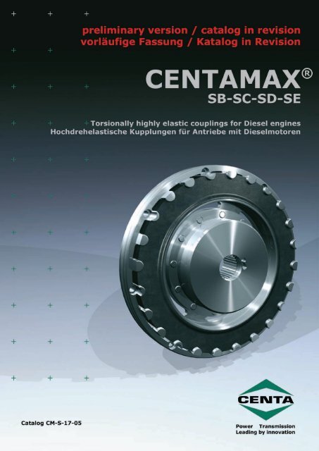
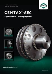
CENTAMAX ®IntroductionEinleitungCENTAMAX-SThese torsional highly elastic CENTAMAX couplings werefirst introduced in 1980. Since that time they have beenproved in numerous difficult applications.This coupling has been developed and tested followingintensive research, calculations and market studies forthe following areas of application:Drives subject to torsional vibration especially diesel enginedrives, where the driven components have relativelysmall inertias and are required to run over a wide speedrange from low idling rpm to full engine speed, free fromdangerous resonances. For these applications it is desirableto shift the critical speeds far enough below engineidling speed so that the whole engine working speedrange can be utilized without limitation.For such drives a torsionally very soft coupling is moredesirable than a torsionally stiff coupling because thewhole drive power train is then subjected to very lowvibratory torques and is therefore more lowly stressed.CENTAMAX couplings are amongst the highest torsionallyelastic couplings available on the market, with a torsionaldeflection of about 12° at nominal torque and about 30°at maximum torque for types SB.For the larger types, SC and SD, the torsional deflection isintentionally lower; it is about 6 – 8° at rated torque.Important Areas of Application:• Splitter gears, with several hydraulic pumps• Compressors• Ship propulsion• Generator sets• Pumping sets• LocomotivesCENTAMAX-SDiese sehr drehelastische Kupplung wurde 1980 vonder Firma CENTA Antriebe entwickelt und auf den Marktgebracht. Sie hat sich seitdem in tausenden schwierigenEinsatzfällen bestens bewährt.Nach eingehenden Überlegungen, Berechnungen undMarktstudien wurde diese Kupplung ganz gezielt für folgendeEinsatzgebiete erprobt und entwickelt:Antriebe mit Drehschwingungen, insbesondere mitDieselmotoren, wobei relativ kleine Trägheitsmassenüber einen weiten Drehzahlbereich, möglichst bis zumniedrigen Leerlauf, ohne gefährliche Resonanzstellenangetrieben werden sollen. Es sollen also die Resonanzenauf niedrige Drehzahlen verschoben werden, so daßder gesamte Betriebsdrehzahlbereich des Motors nachMöglichkeit ohne Einschränkung genutzt werden kann.Für derartige Antriebe ist also eine extrem drehelastischeKupplung vorteilhafter als eine drehsteife Kupplung, weildadurch der gesamte Antriebsstrang bei Betriebsdrehzahlennur mit sehr geringen Dauerwechselmomenten belastetund somit sehr geschont wird.Die CENTAMAX gehört in dieser Hinsicht zu den hochelastischstenKupplungen des Marktes. Bei der Bauform SBbeträgt der Verdrehwinkel bei Nenndrehmoment je nachAusführung ca. 12° und bei Maximalmoment ca. 30°.Bei den Bauformen SC und SD, die bewußt etwas drehsteiferausgelegt wurden, beträgt der Verdrehwinkel beiNenndrehmoment ca. 6 - 8°.Wichtige Einsatzgebiete:• Pumpenverteilergetriebe mit mehrerenhydraulischen Pumpen• Schraubenverdichter• Schiffsantriebe• Generatoren• Lokomotiven• KreiselpumpenCM-S-CENTA Power Transmission leading by innovation
CENTAMAX ®For generator sets the following characteristics ofthe CENTAMAX couplings are very advantageous:• Suited for blindfitting when set is flangemounted.• Free of backlash, even after long service time, thereforeno creation of noise at idling or low load conditions.• Linear characteristic, that means resonances are notshifted by the load, important for sets which mustalso work satisfactorily under misfiring conditions.• Limitation of torque: at extreme overload (e.g. shortcircuit or wrong synchronizing), the coupling elementwill slip on the outer teeth and thereby protect engineand generator against dangerous overloads (slip torqueis about 56 times rated torque). If this happens fromtime to time, the coupling will not be damaged. If itshould happen frequently, then no dangerous brokenmetal pieces will be catapulted away, only harmlessrubber particles which will neither hurt anybody norcause further damage.CENTAMAX and CENTALOC are registered Trademarks ofCENTA Antriebe.Bei Generatorantrieben sind folgende Eigenschaftender CENTAMAX Kupplungen besonders vorteilhaft:• Steckbar: bequeme Montage bei geflanschten Generatoren.• Spielfrei: auch nach längerer Laufzeit, keine Geräuschbildungdurch Drehschwingungen bei Leerlauf odergeringer Teillast.• Lineare Kennlinie: d. h. keine Verschiebung der Resonanzenbei Teillast; wichtig für Antriebe, die auch beiZylinderaussetzer betriebssicher sein müssen.• Drehmomentbegrenzung: Bei extremer Überlastung(z. B. durch Kurzschluß oder Fehlsynchronisierung)rutscht die Kupplung an der äußeren Verzahnungdurch und schützt damit Motor und Generator vorSchäden durch Überlastung. (Durchrutschmoment ca.fünf bis sechsfaches Nenndrehmoment). Tritt dieserFall gelegentlich auf, nimmt die Kupplung dabei keinenSchaden. Falls jedoch durch häufige Überlastung dieKupplung beschädigt wird, so werden keine gefährlichezerbrochene Metallteile weggeschleudert, sondern nurharmloser Gummiabrieb, der weder verletzen kann,noch Folgeschäden verursacht.CENTAMAX und CENTALOC sind eingetragene Warenzeichender Firma CENTA Antriebe.CM-S-3CENTA Power Transmission leading by innovation
CENTAMAX ®Important characteristics and advantages• Torsionally very soft, no backlash.• Linear characteristic.• Torsional stiffness can be adjusted by choice of differentShore hardness discs.• Temperature resistant.• Dampens vibration and shock loads, accepts axial, radialand angular misalignment.• Good heat dissipation due to special airflow over disc.• Suitable for high speeds.• Hub accepts large bores.• No wearing parts, long life, reliable, maintenancefree.• Compact, slim design, input flange dimensions to SAEJ620 for the connection of two shafts.• Easy installation, designed for blind fitting.• The rubber disc is free to float axially in the outer ringand no axial forces are generated by the transmissionof torque.Wichtige Eigenschaften und Vorteile:• sehr drehelastisch, spielfrei• lineare Kennlinie• durch verschiedene Shorehärten kann die Drehsteifigkeitden schwingungstechnischen Erfordernissen angepaßtwerden• dämpft Schwingungen und Stöße, gleicht axiale, radialeund winkelige Fluchtungsfehler aus.• allseitige Belüftung (Kühlung) der Gummischeibe• temperaturbeständig• geeignet für hohe Drehzahlen• große zulässige Bohrungen• verschleißfrei, langlebig, betriebssicher, wartungsfrei• kompakte, kurze Bauform: Anschlußmaße nach SAEJ620 oder zur Verbindung von 2 Wellen• einfache Montage, axial steckbar• axial frei beweglich und frei von drehmomentbedingtenaxialen Kräften.DesignA rubber disc which has moulded teeth on its outside diameteris engaged into an internally toothed aluminiumring that is usually driven by a flywheel. The centre of therubber disc is vulcanized to an inner driven hub.The rubber disc has a designed shape to ensure that equalstress occurs over most of its section, thus providing alarge torsional angle and avoiding high stress in these areas.However, on the inner vulcanized surface and on the outerteeth at these points, the loading of the rubber is reducedto a much lower level than is normally accepted, thus providinga very reliable drive.The design described above — vulcanization to the innerhub, with tooth engagement on the outer ring — has thefollowing advantages:Long elastic length providing high torsional deflection angle,wear and backlash-free rubber connection betweeninner and outer hubs, ensures troublefree operation —simple, compact, reliable and long lastingKonstruktionDie Leistungsübertragung geht bei der CENTAMAX üblicherweisevon einem Motorschwungrad über einen Leichtmetallringund von dort über eine Verzahnung formschlüssigauf eine Gummischeibe und von dieser auf dieanvulkanisierte innere Abtriebsnabe.Der scheibenförmige Gummikörper ist so ausgebildet, daßüber möglichst weite Bereiche eine gleichhohe Schubspannungauftritt, um einerseits möglichst große Verdrehwinkelzu erzielen und andererseits Spannungsspitzen zuvermeiden.An der inneren Vulkanisationsfläche und an der äußerenVerzahnung ist jedoch der Querschnitt überproportionalausgelegt, um dort noch niedrigere spezifische Belastungenzu erhalten. Durch diese niedrige spezifische Belastungist die Vulkanisation der inneren Nabe sehr niedrigbeansprucht, weitaus niedriger als üblich, und somit sehrbetriebssicher.Das hier beschriebene Konstruktionsprinzip: Vulkanisationan innerer Nabe — Verzahnung an äusserer Nabe — hatfolgende Vorteile:Große elastische Länge, somit große Verdrehwinkel, unproblematische,verschleißfreie und spielfreie Überleitungder Kräfte vom Gummi zu den metallischen Anschlußteilen,einfache, kompakte, betriebssichere und langlebigeBauweise.CM-S-CENTA Power Transmission leading by innovation
CENTAMAX ®Hub DesignNaben-BauformenFlywheel — ShaftType SB — Sizes 120–2400The driven inner hub consists of twopieces, the vulcanized steel ring and theinner steel-boss.These two parts are bolted together andthe drive is transmitted by the frictionforce created by the axial bolts, drawingthe tapered hub onto a mating taper inthe element.This connection is very conservativelydimensioned but it can be easily disassembledif the coupling has to be removed.The steel ring to which the elementis vulcanized creates very highinward pressure acting on the innerdriven hub. In order to utilize this pressure,the driven hub can be slotted inan axial direction. This allows the drivenhub to be compressed and provides avery strong backlash free connection betweenthe driven hub and driven shaft.This effect can be used equally well onparallel cylindrical shafts with keys orsplined shafts, and is absolutely free ofback-lash or wear. We call this featureCENTALOC-S-clamping.Refers to all sizes: Further figures afterthe type designation refer to the lengthof the inner hub (boss) or to specialhubs. e. g., SB 1 means standard lengthof hub, SB 2 means longer hub a.s.o.Verbindung Schwungrad – WelleBauform SB — Größen 120–2400Die innere Abtriebsnabe ist zweiteiligausgeführt, sie besteht aus dem einvulkanisiertenStahlring und der eigentlicheninneren Stahlnabe.Diese beiden Teile sind über einen Konusreibschlüssig miteinander verbunden;die Anpreßkraft wird durch Schraubenauf den Konusring aufgebracht.Diese Verbindung ist einerseits sehr sicherdimensioniert, andererseits aberleicht lösbar, falls die Kupplung demontiertwerden muß. Durch den Stahlringwird über den Konus ein sehr hoher,nach innen gerichteter Druck auf dieinnere Nabe aufgebracht. Um diesenradialen Druck auszunutzen, kann dieinnere Nabe mit einem Längsschlitz versehenwerden. Dann ergibt sich durchdas Zusammenpressen der innerenNabe gleichzeitig eine sehr feste undspielfreie Verbindung zwischen Nabeund Welle. Dieser Effekt kann sowohlbei normalen zylindrischen Wellen undinsbesondere bei Wellen mit VielkeiloderEvolventenverzahnung vorteilhafteingesetzt werden, weil sich dadurcheine völlig spielfreie, d.h. verschleißfreieVerbindung ergibt, genannt CENTALOC-S-Klemmung. Weitere Ziffern nach derBauform bezeichnen die Nabenlängebzw. Sondernaben. Zum Beispiel: SB 1bedeutet Standardnabenlänge; SB 2 bedeutetverlängerte Nabe, usw.Type SC — Sizes 2600–18000A pot-shaped flange made of spheroidalcast iron is vulcanized into the rubberelement. This flange is bolted with generouslydimensioned bolts to the innerboss.Depending upon the position (arrangement)of the rubber element, two differentlengths are achieved with the sameparts.Short version: SCALong version : SCBCM-S-Bauform SC- Größen 2600–18000In das Gummielement einvulkanisiertist ein topfförmiger Flansch aus Sphäroguß.Dieser Flansch wird über reichlichdimensionierte Schrauben reibschlüssigmit der inneren Stahlnabe verbunden.Je nach Anordnung des Gummielementesergeben sich mit den gleichen Teilen2 verschiedene Baulängen:kurze Bauform: SCAlange Bauform: SCBCENTA Power Transmission leading by innovation
CENTAMAX ®Type SDSizes 4000, 8000 and 18000This type is comprised of 2 rubber elements- parallel acting - which are boltedto the hub in order to double the torquecapacity. This version is basically possiblefor the sizes 2800, 4000, 8000, 12000and 18000.Bauform SDGrößen 4000, 8000 und 18000Bei dieser Bauform werden 2 Gummielemente- parallel angeordnet - mit derNabe verschraubt, um das übertragbareDrehmoment zu verdoppeln. Diese Anordnungist grundsätzlich möglich fürdie Baugrößen 2800, 4000, 8000, 12000und 18000.Types SBE, SCE and SDESizes 240–18000Flywheel - shaft connectionThese versions are particularly advantageouson larger sizes of couplings. Therubber element can easily and quickly bechanged without disturbing the coupledshafts in these types on independentlymounted, nonflanged sets, providedthat the flywheel housing does not protrudetoo far over the coupling unit. Ifthey protrude too much, then the couplingelement can nevertheless be changedradially, if an additional spacer ringis provided between the driven hub andelement, as shown on Picture 4, Page18.The designation SDE indicates couplingswith 2 elements, Sizes 4000 SDE, 8000SDE, 12000 SDE and 18000 SDE.For the sizes 240 - 2400 SBE, the vulcanizedhub in the element is different - ithas additional taped holes.For the sizes 2800 - 18000-D, the elementis identical to other types, but anadditional steel clamp ring is used.CM-S-Bauform SBE, SCE und SDEGrößen 240–18000Verbindung Schwungrad – WelleBei dieser Bauform für frei aufgestellte,nicht geflanschte Aggregate kanndas Gummielement bequem und schnellausgewechselt werden, ohne daß diegekuppelten Aggregate bewegt werdenmüssen. Voraussetzung ist dabei nur,daß das Schwungrad bzw. Schwungradgehäusenicht zu weit über die Kupplungragt. Sollten Schwungrad oderSchwungradgehäuse jedoch zu weit überdie Kupplung ragen, dann ist die Kupplungtrotzdem radial tauschbar, wenn einzusätzlicher Distanzring zwischen Nabeund elastischem Element angeordnetwird. (Siehe Seite 18, Bild 4).Diese Bauform ist vor allem für grössereAggregate wichtig. Die Bezeichnung SDEgilt für die Baugrößen 4000 SDE, 8000SDE, 12000 SDE und 18000 SDE.Bei den Baugrößen 240 - 2400 SBE unterscheidetsich die in das Gummielementeinvulkanisierte innere Nabe von denübrigen Bauformen, sie hat zusätzlicheGewindebohrungen. Bei den Baugrössen2800 - 18000-D ist das Gummielementidentisch mit den übrigen Bauformen,es wird lediglich ein Ring mit den entsprechendenGewindebohrungen hinzugefügt.CENTA Power Transmission leading by innovation
CENTAMAX ®Types SBEW, SCEW, SDEWRadial assembly/disassembly typesfor shaft-to-shaft drivesSizes 240–18000This type is for the connection of 2 shaftswhere the element can be removed radiallywithout disturbing the driving or drivenshafts. Here single cylindrical steelbolts are used instead of the aluminiumteeth in the outer ring which engagewith the toothed rubber disc, exept onthe size 8000 SDEW (with double elements)where an outer aluminium ringis used.Bauform SBEW, SCEW und SDEWGrößen 240–18000Verbindung Welle – WelleDiese Bauform dient zur Verbindung von2 Wellen, und sie ermöglicht gleichfallsden Wechsel der Elemente ohne Verschiebungder gekuppelten Aggregate(wie Bauform SE).Anstelle des verzahnten äußeren Ringssind hier einzelne zylindrische Bolzenangeordnet, die in die Verzahnung desGummielementes eingreifen.Nur bei der Größe 8000 SDEW mit doppeltemElement ist der entsprechendeäußere Aluminiumring (wie SAE 18) angeordnet.Types SBW, SCW, SDWSizes 240–18000Shaft to shaftThis type is shorter and lower in pricethan the drop-out types. The couplinghalves can be assembled radially — likea ‘three-piece’ coupling — but the elementcannot be changed without disturbingthe shafts.Bauform SBW, SCW und SDWGrößen 240–18000Verbindung Welle – WelleDiese Wellenbauform ist kürzer undpreiswerter als die radial tauschbareBauform EW. Die Kupplung kann radial(quer) montiert werden wie eine „dreiteilige“Kupplung, jedoch kann das Gummielementin eingebautem Zustand derKupplung nicht gewechselt werden.Special TypesIn addition to the standard types shownhere, we have developed many specialtypes.Samples are shown on Page 18.SonderbauformenNeben den hier gezeigten Standard-Bauformen haben wir zahlreiche Sonderbauformenentwickelt.Beispiele finden Sie auf Seite 18.CM-S-CENTA Power Transmission leading by innovation
CENTAMAX ®Selection of CENTAMAX couplingsThe following well-known formula can be used for the preliminarycoupling selection, based on transmitted torque:T = Pn· 9550Provided that: T < T KN· S t1P = Power [kW]n = Speed [rpm]T = Transmitted torque [Nm]T KN= Nominal torque of coupling [Nm]In closed flywheel housings there is always an ambienttemperature of at least 60°C - 70°C.For reliable coupling selection on drives subject to torsionalvibration (diesel engines, piston compressors etc.)a torsional vibration analysis is necessary.If requested, we will carry out the calculations (free ofcharge) using our own computer program, upon receipt ofthe drive details.Auslegung der CENTAMAX-KupplungenEine überschlägige Zuordnung, ausgehend vom zu übertragendenDrehmoment, kann zunächst nach folgenderbekannter Formel erfolgen:T = Pn· 9550Bedingung ist: T < T KN· S t1P = Leistung [kW]n = Drehzahl [min -1 ]T = Drehmoment [Nm]T KN= Nenndrehmoment der Kupplung [Nm]In geschlossenen Schwungradgehäusen muß immer mitTemperaturen von mindestens 60°C bis 70°C gerechnetwerden.Für eine betriebssichere Auslegung bei Antrieben mitDrehschwingungen (Dieselantriebe, Kolbenmaschinen) istjedoch immer eine Drehschwingungsrechnung erforderlich.Die dazu erforderlichen Daten der Kupplungen findenSie in diesem Katalog. Wir führen für Sie auch gern solcheDrehschwingungsrechnungen durch, wofür wir eigeneComputerprogramme entwickelt haben.Since these couplings are normally only applied to drivesrunning over critical, i.e. work speeds above resonancespeeds, the following details must be checked:• Where are the resonance speeds? There must be sufficientdistance between the main resonance speed andlowest working or idling speed.• Is the maximum vibratory torque when passing throughresonance lower than the coupling value for T Kmax?• Is the continuous vibratory torque T Wat working speedlower than the allowable vibratory torque T KWof thecoupling, considering the frequency factor S fand thetemperature factor S t2, or is the total loss of energy P V(by damping) from all the single orders lower than theallowable loss of energy P KV, considering the temperaturefactor S t2?Da diese Kupplung sinnvollerweise nur bei überkritischemBetrieb eingesetzt wird, d. h. die Betriebsdrehzahlen liegenoberhalb der kritischen Drehzahlen (Resonanzen),sollten folgende Kriterien überprüft werden:• Lage der Resonanzdrehzahlen, d. h. ist genügend Abstandder Resonanzen zur niedrigsten Betriebsdrehzahlbzw. Leerlauf gegeben?• Sind die beim Durchfahren der Resonanzen auftretendenWechseldrehmomente zulässig, d. h. kleiner alsT Kmaxder Kupplung?• Ist das im Betrieb vorhandene Dauerwechseldrehmomentzulässig, d. h. kleiner als das zul. DauerwechseldrehmomentT KWder Kupplung, unter Berücksichtigungdes Frequenzfaktors S fund des Temperaturfaktors S t2,bzw. ist die Summe der Verlustleistungen P Vaus deneinzelnen Ordnungen kleiner als die zulässige VerlustleistungP KV, unter Berücksichtigung des TemperaturfaktorsS t2?CM-S-CENTA Power Transmission leading by innovation
CENTAMAX ®The CENTAMAX couplings are robust and reliable, but withthe wrong torsional situation every coupling, and possiblythe whole power train, is in danger. Therefore it is ofthe utmost importance to ensure that torsional vibrationcalculations are made at the beginning of the couplingselection procedure.The technical data on the next page refers only to thecouplings as such. This is, for example, no indication forensuring that the bolts attaching the flywheel flange ontothe flywheel can always transmit these torques, especiallywhen relatively small flanges are used. In these casesadditional or larger bolts and/or dowel pins must be provided.If there are several SAE flange fittings provided inthe flywheel, the largest one should be preferred. It is theresponsibility of the customer to check this point as wellas the other points such as the dimensions of shafts andkeys, or any other connection to the coupling.The CENTA range of couplings is one of the broadest rangesavailable with couplings available in many stiffnessgrades from torsionally very stiff to torsionally very soft.Thus, using our worldwide experience in solving torsionalvibration problems and our awareness of its importance,we can recommed the most suitable coupling for almostany application without compromising design standards.This ensures reliable and troublefree coupling operation.Die CENTAMAX-Kupplungen sind robust, aber bei falscherDrehschwingungslage ist jede Kupplung gefährdet, unterUmständen der gesamte Antriebsstrang. Darum ist es sowichtig, die Drehschwingungslage zu berechnen und vonAnfang an eine geeignete Kupplung vorzusehen.Die folgenden technischen Daten beziehen sich nur aufdie Kupplung als solche. Damit ist z. B. nicht ausgesagt,ob die Verschraubung des SAE-Flansches am Schwungradimmer diese Drehmomente übertragen kann, insbesonderedann, wenn relativ kleine Flansche eingesetzt werden.Dann müssen gegebenenfalls zusätzliche oder grössereSchrauben und/oder Stifte vorgesehen werden. Stehenmehrere SAE-Anschlüsse zur Wahl, sollte der grösserevorgezogen werden. Die Überprüfung dieses Punktes,ebenso wie die Verantwortung für die Dimensionierungvon Wellen und Paßfedern oder sonstigen Verbindungenmit der Kupplung liegt beim Anwender.Die Fa. CENTA bietet eines der umfangreichsten Kupplungsprogrammemit Kupplungen aller Drehsteifigkeitsgrade,von sehr drehsteif bis extrem drehelastisch. Daher,und weil wir speziell Erfahrung mit Drehschwingungenhaben, können wir für fast jeden Fall die objektiv richtigeKupplung für betriebssichere Antriebe vorschlagen.CM-S-10CENTA Power Transmission leading by innovation
CENTAMAX ®Technical Data for NRCENTAMAXsizeGrösseShoreANominalTorqueShorehardnessGummiqualitätNenndrehmomentT KN[Nm]MaximumTorqueMaximalDrehmomentT Kmax[Nm]Continuousvibr. Torque at10 HzZul. Wechseldrehmomentbei 10 HzT KW[Nm]AllowableEnergy LossZulässige VerlustleistungP KV[W]Dyn. TorsionalStiffnessDyn. DrehsteifigkeitC Tdyn[Nm/rad]35 100 250 40 150Flange SizeSAE J620FlanschgrösseSAE J620Max. SpeedMax. Drehzahln max[min -1 ]40 110 280 44 200 6,5 5000 0,0063Technische Daten für NRMass moments of inertiapreboredprimary** secondaryMassenträgheitsmomentevorgebohrtprimär** sekundärJJ[kgm 2 ] [kgm 2 ]120-S 50 120 300 48 20 300 7,5 4500 0,01050,001860 140 350 56 500 8 4500 0,015970 150 400 60 80050 250 500 100 925 8 4000 0,0208240-S 60 300 600 120 37 1400 10 3600 0,03130,003870 350 750 140 225050 400 800 160 1600400-S 60 500 1000 200 62 2500 10 3600 0,0373 0,011470 550 1100 220 400050 700 1400 280 2800 10 3600 0,0599800-S 60 850 1700 340 105 4200 11,5 3500 0,07320,029670 950 2000 380 6800 14 3000 0,137850 1000 2000 400 4500 11,5 3500 0,07681200-S 60 1200 2400 480 150 7000 14 3000 0,14320,045670 1300 3000 520 1170050 1450 2900 580 6000 11,5** 3200 0,22401600-S 60 1800 3600 720 220 9000 14 3000 0,19700,078070 2000 4000 800 13500 16 2500 0,274050 2000 4000 800 10000 14 3000 0,21302400-S 60 2500 5000 1000 300 15000 16 2500 0,29000,153070 2800 6000 1120 22500 18 2300 0,401550 2500 5000 1000 9500 14 3000 0,26362600-S 60 2700 6000 1080 350 13500 16 2500 0,41880,212170 3000 7000 1200 22000 18 2300 0,567350 2800 6000 1120 25000 14 3000 0,23862800-S 60 3000 7500 1200 360 37500 16 2500 0,31580,225770 3200 8000 1280 63000 18 2300 0,427150 3200 6500 1280 16000 14 3000 0,28363500-S 60 3500 8000 1400 450 24000 16 2500 0,43880,229570 3800 8500 1520 38000 18 2300 0,587350 4000 8000 1600 3400060 4500 11000 1800 50000 14 3000 0,28384000-S 70 5000 12500 2000 500 80000 16 2500 0,41720,541572 5500 12500 2200 112000 18 2300 0,565575 6000 12500 2400 168000Technical data according DIN 740.* Constant value due to linear characteristics.** Primary side means flange side on flywheel types.*** Dimensions on request - Service factors please refer to page 12.CM-S-11technische Daten entsprechend DIN 740* konstanter Wert, da lineare Kennlinie** Primärseite=Flanschseite. Wert gilt für Schwungradbauformen*** Abmessungen auf Anfrage - Betriebsfaktoren siehe Seite 12CENTA Power Transmission leading by innovation
CENTAMAX ®Technical Data for NRCENTAMAXsizeGrösseShoreANominalTorqueShorehardnessGummiqualitätNenndrehmomentT KN[Nm]MaximumTorqueMaximalDrehmomentT Kmax[Nm]Continuousvibr. Torque at10 HzZul. Wechseldrehmomentbei 10 HzT KW[Nm]AllowableEnergy LossZulässige VerlustleistungP KV[W]Dyn. TorsionalStiffnessDyn. DrehsteifigkeitC Tdyn[Nm/rad]50 4500 9000 1800 17000Flange SizeSAE J620FlanschgrösseSAE J620Max. SpeedMax. Drehzahln max[min -1 ]60 5000 10000 2000 27000 14 3000 0,31615000-S 70 6000 12000 2400 500 45000 16 2500 0,471372 6500 12000 2600 57000 18 2500 0,679875 7000 12000 2800 9000050 6300 12600 2520 2850060 7000 14000 2800 45000Technische Daten für NRMass moments of inertiapreboredprimary** secondaryMassenträgheitsmomentevorgebohrtprimär** sekundärJJ[kgm 2 ] [kgm 2 ]7000-S 70 7900 15800 3160 750 67000 18 2500 0,7820 0,586072 8700 15800 3480 9500075 9500 15800 3800 16000050 8000 16000 3200 6800060 9000 22000 3600 100000 14 3000 0,67894000-SD 70 10000 25000 4000 1000 160000 16 2500 0,784672 11000 25000 4400 224000 18 2500 0,929975 12000 25000 4800 33600050 8000 16000 3200 6000060 9000 22000 3600 80000 18 2500 0,97878000-S 70 10000 25000 4000 1000 130000 21 2300 1,432772 11000 25000 4400 18200075 12000 25000 4800 273000 24 2000 1,834050 8000 16000 3200 5100060 9000 22000 3600 68000 18 2500 0,77109000-S 70 10000 25000 4000 1000 110000 21 2300 1,225 0,967072 11000 25000 4400 155000 24 2000 1,62675 12000 25000 4800 23200072 13800 25000 5520 195000 18 2500 1,022010000-S 75 15000 25000 6000 1100 330000 21 2300 1,389050 16000 32000 6400 12000024 2000 1,715060 18000 44000 7200 160000 18 2500 1,99708000-SD 70 20000 50000 8000 2000 260000 21 2300 2,411472 22000 50000 8800 364000 24 2000 2,836575 24000 50000 9600 54600072 27600 50000 11040 390000 18 2500 2,084010000-SD 75 30000 50000 12000 2200 660000 21 2300 2,616050 12500 25000 5000 7900060 14000 28000 5600 11500024 2000 3,029012000-S 70 15000 30000 6000 1100 188000 21 2300 3,209072 16500 30000 6600 263000 24 2000 4,359075 18000 30000 7200 395000Technical data according DIN 740.* Constant value due to linear characteristics.** Primary side means flange side on flywheel types.*** Dimensions on request - Service factors please refer to page 12.technische Daten entsprechend DIN 740* konstanter Wert, da lineare Kennlinie** Primärseite=Flanschseite. Wert gilt für Schwungradbauformen*** Abmessungen auf Anfrage - Betriebsfaktoren siehe Seite 120,23440,58991,13371,48402,24362,73001,9410CM-S-12CENTA Power Transmission leading by innovation
CENTAMAX ®Technical Data for NRCENTAMAXsizeGrösseShoreANominalTorqueShorehardnessGummiqualitätNenndrehmomentT KN[Nm]MaximumTorqueMaximalDrehmomentT Kmax[Nm]Continuousvibr. Torque at10 HzZul. Wechseldrehmomentbei 10 HzT KW[Nm]AllowableEnergy LossZulässige VerlustleistungP KV[W]Dyn. TorsionalStiffnessDyn. DrehsteifigkeitC Tdyn[Nm/rad]50 16000 32000 6400 11500060 18000 36000 7200 170000Flange SizeSAE J620FlanschgrösseSAE J620Max. SpeedMax. Drehzahln max[min -1 ]18000-S 70 20000 40000 8000 1200 282000 21 2300 3,261072 22000 40000 8800 395000 24 2000 4,501075 24000 40000 9600 59000050 25000 50000 10000 15800060 28000 56000 11200 23000012000-SD 70 30000 60000 12000 2200 376000 21 2300 6,367072 33000 60000 13200 526000 24 2000 7,557075 36000 60000 14400 79000050 32000 60000 12800 23000060 36000 60000 14400 34000018000-SD 70 40000 60000 16000 2400 564000 21 2300 6,460072 44000 60000 17600 790000 24 2000 7,841075 48000 60000 19200 1180000Technical data according DIN 740.* Constant value due to linear characteristics.** Primary side means flange side on flywheel types.*** Dimensions on request - Service factors please refer to page 12.Technische Daten für NRMass moments of inertiapreboredprimary** secondaryMassenträgheitsmomentevorgebohrtprimär** sekundärJJ[kgm 2 ] [kgm 2 ]technische Daten entsprechend DIN 740* konstanter Wert, da lineare Kennlinie** Primärseite=Flanschseite. Wert gilt für Schwungradbauformen*** Abmessungen auf Anfrage - Betriebsfaktoren siehe Seite 122,17703,13203,8090Temperature factorsTemperaturfaktorenfor dynamic torsionalstiffness C Tdynfür dynamischeDrehsteifigkeit C TdynAllowable energy loss P KVVerlustleistung P KV1,0S t210,90,90,80,7S t20,80,6S t3 50° Sh60° Sh0,50,70,670° Sh0,40,30,20,10,5030 40 50 60 70 80 90 °C30 40 50 60 70 80 90 °C86 104 122 140 158 176 184 °F86 104 122 140 158 176 184 °FFrequency Factor S fFrequenzfaktor S ff [Hz] ≤ 10 > 10S f1f10Resonance factor V RRel. damping factor ΨResonanzfaktor V RRelative Dämpfung ΨNatural Rubber (NR)Shore hardness V RΨ35 - 40 12 0,5250 6,0 1,0560 5,7 1,170 5,5 1,1572 4,8 1,3075 4,8 1,30CM-S-13CENTA Power Transmission leading by innovation
CENTAMAX ®Technical Data for Silicone - 50 ShoreSizeGrösseNominalTorqueNenndrehmomentT KN[Nm]MaximumTorque 1Max. Drehmoment1T Kmax1[Nm]MaximumTorque 2Max. Drehmoment2T Kmax2[Nm]ContinousvibratoryTorqueZulässigesWechseldrehmomentT KW[Nm]AllowablePower LossZulässigeVerlustleistungP KV[W]Technische Daten für Silikon - 50 ShoreDynamic Torsional Stiffness 3,4Dynamische Drehsteifigkeit10% 25% 50% 75% 100%C Tdyn[Nm/rad]RelativeDampingRelativeDämpfung800 700 1050 1400 280 105 2200 2400 2800 3500 4600 1,151200 1000 1500 2000 400 150 3600 3900 4500 5600 7400 1,151600 1450 2175 2900 580 220 4800 5200 6000 7500 9900 1,152400 2000 3000 4000 800 300 7650 8000 9200 11500 15200 1,152600 2500 3750 5000 1000 350 7200 7800 9000 11800 18000 1,152800 2800 4200 5600 1120 360 21000 23000 25000 32500 42500 1,153500 3200 4800 6400 1280 450 12800 13900 15000 19500 26500 1,154000 4000 6000 8000 1600 500 29000 31000 34000 45000 62000 1,155000 5000 7500 10000 2000 500 13600 14800 16000 21300 32000 1,157000 6300 9450 12600 2500 750 22400 24400 28500 35000 46000 1,158000 8000 12000 16000 3200 1000 51000 55000 60000 78000 102000 1,159000 8000 12000 16000 3200 1000 43400 47000 51000 66300 86700 1,1510000 10000 15000 20000 4000 1000 50600 54700 59500 77400 101000 1,1512000 12500 18750 25000 5000 1100 63000 67800 79000 98000 130000 1,1518000 16000 24000 32000 6400 1200 93000 100000 115000 144000 190000 1,15Ψ1) The torque T Kmax1is allowable during transient working conditions, e.g. passingof resonances during starting or stopping of the engine and during acceleration,deceleration and clutching operation.2) The maximum torque T Kmax2is the absolute highest permissible peak torquefor rare occasions such as short circuit, wrong synchronisation etc., howeversuch events should be avoided as far as possible.3) The CENTAMAX in Silicone have a progressive characteristic.4) Due to material, value tolerances off ±15% are possible.1) Das Drehmoment T Kmax1ist zulässig während transienten Betriebszuständen, wiez.B. An- und Abstellen mit Resonanzdurchgang, Beschleunigungs-, Brems- undSchaltvorgängen.2) Das maximale Drehmoment T kmax2ist das absolut höchstzulässige Drehmomentfür selten auftretende Lastspitzen wie z.B. Kurzschluß, Fehlsynchronisation u.a.,die jedoch möglichst vermieden werden sollten.3) Die CENTAMAX in Silikon hat eine progressive Kennlinie.4) Materialbedingt sind für die Werte Toleranzen von ±15% möglich.Allowable energy loss P KVVerlustleistung P KVN KN TKN Nominal torque of coupling1,6 - 2 ∙ T ≤ TTN Nominal torque of driveNenndrehmoment des AntriebsNenndrehmoment der KupplungCM-S-14CENTA Power Transmission leading by innovation
CENTAMAX ®DimensionsAbmessungen120-2400-SB2600-12000-SCAStandard types – Flange sizes to SAESizeSAEJ620Standardbauformen – Flansche nach SAEA C* d 1d 3D BE L L 1N 1WeightGrösseGewichtmin. max. [kg]6,52,6120 SB1 7,5 43 64±2 12 42 220 42 20 56 42 672,98 3,2240 SB182626,146 75±9 15 5050 27 75 60 7310 225 6,5400 SB1 10 45 75±7 20 60 313 61 25 80 65 90 8,610 50 82±231611,1800 SB1 11,5 39 71±3 20 70 351 71 18 84 66 10710,114 46 74±6 318 11,51200 SB111,5** 39 65±435114,520 7071 18 84 66 10714 46 74±1 351 16,41446522,51600 SB1 16 61 97±11 30 105 417 106 26 106 85 15023,818 417 25,31446531,12400 SB1 16 61 97±6 30 105 417 106 26 106 85 15032,418 417 33,92600 SCA496±6- 20 -14 7035 110 4652600 SCB4 135±6 - 59 139100 162 32,32600 SCA496±6- 20 -16 7035 110 4652600 SCB4 135±6 - 59 139100 162 34,92600 SCA496±6- 20 -18 7035 110 4652600 SCB4 135±6 - 59 139100 162 36,92800 SCA493±4- 34 -14 6135 110 4652800 SCB4 130±4 - 76 126100 162 31,52800 SCA493±4- 34 -16 6135 110 4172800 SCB4 130±4 - 76 126100 162 32,82800 SCA493±4- 34 -18 6135 110 4172800 SCB4 130±4 - 76 126100 162 34,33500 SCA496±6- 20 -14 7035 110 4653500 SCB4 135±6 - 59 139100 162 33,93500 SCA496±6- 20 -16 7035 110 4653500 SCB4 135±6 - 59 139100 162 36,63500 SCA496±6- 20 -18 7035 110 4653500 SCB4 135±6 - 59 139100 162 38,54000 SCA1109±6- 42 -14 7050 140 4654000 SCB1 161±6 - 94 159125 218 48,44000 SCA1109±6- 42 -16 7050 140 4654000 SCB1 161±6 - 94 159125 218 51,54000 SCA1109±6- 42 -18 7050 140 4654000 SCB1 161±6 - 94 159125 218 53,8* The dimensions may be varied to suit particular installations, i.e. the rubber canbe moved off-centre from the outer ring, either away from the flywheel or towardsit (if the flywheel contour allows). Within the limits specified for dimension »C«the rubber teeth are always fully engaged in the outer ring. The dimension »L1«can be reduced if necessary with corresponding change to dimension »C«. TheCENTAMAX coupling is very adaptable with regard to axial length.* Um den Betrag der angegebenen Toleranz darf das Einbaumaß variieren, d.h.die Kupplung kann entsprechend weiter auseinandergezogen oder aber auch tieferzusammengeschoben werden, falls das die Kontur des Schwungrades erlaubt.Dabei ist immer noch der volle Eingriff des Gummielementes im äußeren Ringgegeben. Darüber hinaus kann nötigenfalls noch die Nabe gekürzt oder verlängertwerden.**On the size CM-1200 with SAE flange 11.5 the outer aluminium ring protudesinto the flywheel with a diameter of 312 mm and 11 mm axial depth (Page 18,picture 3).** Bei der Baugröße CM-1200 mit SAE 11,5 Anschluß ragt der Aluminiumring mitDurchmesser 312 mm um 11 mm axial in das Schwungrad hinein (Seite 18,Bild 3).CM-S-15CENTA Power Transmission leading by innovation
CENTAMAX ®Standard types – Flange sizes to SAESizeGrösseSAEJ620Standardbauformen – Flansche nach SAEA C* d 1d 3D BE L L 1N 1WeightGewichtmin. max. [kg]5000 SCA193±2- 10 -14 7035 110 4655000 SCB1 147±2 - 64 1595000 SCA193±2- 10 -16 7035 110 4655000 SCB1 147±2 - 64 1595000 SCA193±2- 10 -18 7035 110 4655000 SCB1 147±2 - 64 1597000 SCA1123±9- 4018 8050 140 5707000 SCB1 159±9 - 764000 SD114156±8105 162 35,5105 162 38,2105 162 40,1161 125 218 63,616 145 156±8 50 150 465 - 16 150 150 21868,718 156±8 - 718000 SCA1130±5- 42 -18 11170 180 6008000 SCB1 197±5 - 110 1958000 SCA1130±5- 42 -21 9070 180 5848000 SCB1 197±5 - 110 1958000 SCA1130±5- 42 -24 9070 180 5848000 SCB1 197±5 - 110 1959000 SCA1125±2– 42 –18 8070 180 5709000 SCB1 193±2 – 110 1958000 SD1-66,9150 248 94150 248 97150 248 100150 248 88,221-153194 285±5 70 180 584108 284 200 24824 - 15710000 SCA1 18 111 130±5600 - 42 -10000 SCB1 18 111 197±5 600 - 110 195 101,010000 SCA1 21 90 130±5 584 - 42 - 105,070 180150 24810000 SCB1 21 90 197±5 584 - 110 195 105,510000 SCA1 24 90 130±5 584 - 42 - 107,310000 SCB1 24 90 197±5 584 - 110 195 107,312000 SCA1 21 156 200±9- 65 -12000 SCB1 21 156 310±9 - 176 306 145,070 180 680200 24812000 SCA1 24 137 200±9 - 65 - 152,012000 SCB1 24 137 310±9 - 176 306 152,010000 SD1 21 192 285±5- 108170,070 180 600284 200 24810000 SD1 24 192 285±5 - 108 174,012000 SD1 21 290 335±9- 65232,070 180 680250 24612000 SD1 24 290 335±9 - 65 241,018000 SCA1 21 156 200±9- 65 -18000 SCB1 21 156 310±9 - 176 306 152,070 180 680200 24818000 SCA1 24 137 200±9 - 65 - 161,018000 SCB1 24 137 310±9 - 176 306 161,018000 SD1 21 290 335±9- 65238,070 180 680250 24618000 SD1 24 290 335±9 - 65 247,0101,0145,0152,0* The dimensions may be varied to suit particular installations, i.e. the rubber canbe moved off-centre from the outer ring, either away from the flywheel or towardsit (if the flywheel contour allows). Within the limits specified for dimension »C«the rubber teeth are always fully engaged in the outer ring. The dimension »L1«can be reduced if necessary with corresponding change to dimension »C«. TheCENTAMAX coupling is very adaptable with regard to axial length.**On the size CM-1200 with SAE flange 11.5 the outer aluminium ring protudesinto the flywheel with a diameter of 312 mm and 11 mm axial depth (Page 18,picture 3).* Um den Betrag der angegebenen Toleranz darf das Einbaumaß variieren, d.h.die Kupplung kann entsprechend weiter auseinandergezogen oder aber auch tieferzusammengeschoben werden, falls das die Kontur des Schwungrades erlaubt.Dabei ist immer noch der volle Eingriff des Gummielementes im äußeren Ringgegeben. Darüber hinaus kann nötigenfalls noch die Nabe gekürzt oder verlängertwerden.** Bei der Baugröße CM-1200 mit SAE 11,5 Anschluß ragt der Aluminiumring mitDurchmesser 312 mm um 11 mm axial in das Schwungrad hinein (Seite 18,Bild 3).CM-S-16CENTA Power Transmission leading by innovation
CENTAMAX ®DimensionsAbmessungen2600-18000-SCB4000-18000-SDTypes for Generators to DIN 6281 Bauformen für Generatoren nach DIN 6281Size SAE Generator size A C d 1d 3D BE L L 1N 1WeightGrösse J620 Generator Kenngrösse Gewicht240 SB1 10 A 46 73400 SB1 10 A 45 73min. max. [kg]+11- 7 - 50 225 50 27 75 60 73 6,5+9- 5 - 60 313 61 25 80 65 90 8,6800 SB3 10 A 50 73 ±2 - 70 316 71 9 75 57 107 9,9800 SB2 10 B-C 50 121 ±2 - 75 316 71 57 123 105 107 12,9800 SB3 11,5 A 39 59 +6 - 70 351 71 9 75 57 107 9,5800 SB2 11,5 B-C 39 107 +6 - 75 351 71 57 123 105 107 12,4800 SB4 14 B-C 46 93 ±6 - 70 318 71 42 103 85 107 13,31200 SB2 11,5 B-C-D 39 107+1- 7 - 75 351 71 57 123 105 107 17,21200 SB4 14 B-C 46 93 ±1 - 70 318 71 37 103 85 107 17,71600 SB1 14 B-C-D 61 931600 SB3 16 E 61 832400 SB1 14 C-D-E 61 932400 SB3 16 E 61 83+15- 7 - 105 465 106 26 106 85 150 22,5+15-7 - 105 417 106 16 96 75 150 21,5+10- 2 - 105 465 106 26 106 85 150 31,1+10- 2 - 105 417 106 16 96 75 150 29,82800 SCA4 14 C-D-E 61 93 ±4 - 110 465 - 34 - 100 162 292800 SCA5 16 E 61 83 ±4 - 110 417 - 24 - 90 162 29,53500 SCA4 14 C-D-E 70 933500 SCA5 16 E-F 70 834000 SCA3 14 D-E-F 70 934000 SCA4 16 E-F 70 83For gensets mostly 70 shore are applied, however subject to torsional vibrationanalysis. For many popular Diesel engines we have worked out selectiontables: engine - coupling - allowable range of generator inertia.Thus a convenient, reliable selection is possible. For other generator dimensions,couplings with standard dimensions can also be used.+8- 4 - 110 465 - 20 - 100 162 33,9+8- 4 - 110 465 - 15 - 90 162 35,1+ 2-10 50 140 465 - 22 - 105 218 43,8+11- 1 50 140 465 - 22 - 105 218 46,9Bei Generatoren werden meistens 70 Shore eingesetzt, Shorehärte jedochvorbehaltlich Drehschwingungsberechnung. Für alle gängigen Dieselmotorehaben wir Zuordnungslisten ausgearbeitet: Motor - Kupplung - zulässigerBereich des Generatorträgheitsmomentes. Damit ist eine bequeme, sichereAuswahl möglich. Für andere Generatorabmessungen können auch Standardbauformeneingesetzt werden.Dimensions to SAE J620Anschlussmaße nach SAE J620SAE D AD TZ [°] S6,5 215,9 200,0 6x60 97,5 241,3 222,3 8x45 98 263,5 244,5 6x60 1110 314,3 295,3 8x45 1111,5 352,4 333,4 8x45 1114 466,7 438,2 8x45 1316 517,5 489,0 8x45 1318 571,5 542,9 6x60 1721 673,1 641,4 12x30 1724 733,4 692,2 12x30 19CM-S-17CENTA Power Transmission leading by innovation
CENTAMAX ®DimensionsAbmessungen240-2400 SBE2600-18000 SCE4000-18000 SDEFlange Types to SAE forradial change of elementsFlanschbauformen nach SAE fürradialen Tausch des ElementesSize SAE A C d 1d BE L L 1N 1WeightGrösse J620 Gewichtmin. max. [kg]240 SBE 82624,846 113±2 - 4558 106 60 66240 SBE 10 225 5,2400 SBE 10 45 117±2 - 55 313 63 118 65 85 7,6800 SBE 11,5 39 117±235111,1- 6564 130 66 100800 SBE 14 46 119±2 318 14,01200 SBE 11,5* 39 113±235115,2- 6564 130 66 1001200 SBE 14 46 120±2 318 18,31600 SBE 1446525,21600 SBE 16 61 168±2 - 100 417 88 168 90 140 26,51600 SBE 18 417 28,02400 SBE 1446532,72400 SBE 16 61 163±2 - 100 417 88 168 90 140 34,02400 SBE 18 417 35,52600 SCE 1435,72600 SCE 16 70 185±2 - 105 465 103 183 105 154 38,42600 SCE 18 40,32800 SCE 1446532,32800 SCE 16 61 164±2 - 105 417 103 158 105 154 33,62800 SCE 18 417 35,13500 SCE 1437,33500 SCE 16 70 185±2 - 105 465 103 183 105 154 40,03500 SCE 18 41,94000 SCE 1452,14000 SCE 16 70 198±2 - 140 465 125 190 125 210 56,94000 SCE 18 57,65000 SCE 1438,95000 SCE 16 70 186±2 - 105 465 103 198 105 154 41,65000 SCE 18 43,57000 SCE 18 80 244±2 50 140 570 123 208 125 210 64,04000 SDE 1469,94000 SDE 16 145 220±8 50 150 465 80 214 150 210 71,74000 SDE 18 74,08000 SCE 18 11116598,58000 SCE 21 90 244±2 70 170 600 151 236 150 235 101,58000 SCE 24 90 170104,58000 SDE 21157,5192 320±2 70 170 600 139 315 230 2358000 SDE 24 161,59000 SCE 18 80 239±2 ?? 170 570 148 236 150 235 84,510000 SCE 18 11116597,010000 SCE 21 90 244±2 70 170 600 151 236 150 235 101,010000 SCE 24 90 170 105,510000 SDE 21179,0192 320±2 70 170 600 139 315 230 23510000 SDE 24 183,012000 SCE 21 156680145,0340±5 70 170201 331 200 23512000 SCE 24 137 730 152,012000 SDE 21226,0290 390±2 70 165 680 115 379 250 23212000 SDE 24 245,018000 SCE 21 156680147,0340±5 70 170201 331 200 23518000 SCE 24 137 730 157,018000 SDE 21241,5290 390±2 70 165 680 115 379 250 23218000 SDE 24 252,0Please state Shorehardness and finished bore with your order.Bitte Shorehärte und Fertigbohrung bei Bestellung angeben.* On the size CM-1200 with SAE flange 11.5 the outer aluminium ringprotudes into the flywheel with a diameter of 312 mm and 11 mm axialdepth (Page 18, picture 3).* Bei der Baugröße CM-1200 mit SAE 11,5 Anschluß ragt der Aluminumringmit Durchmesser 312 mm um 11 mm axial in das Schwungradhinein (Seite 18, Bild 3).CM-S-18CENTA Power Transmission leading by innovation
CENTAMAX ®MisalignmentWellenversatzPermissible angular and radialmisalignment is dependant uponthe speed when utilizing the nominaltorque capacity.Zulässige Winkel- und Radialverlagerungin Abhängigkeit von derDrehzahl bei Ausnutzung der Nennleistung.The couplings can accomodate the following maximummisalignment:axial : several mm (as stated in dimension tables)angular : 0.5 degreesradial : 0.5 mmThese values for angular and radial misalignment arebased on 1500 rpm. For other speeds convert accordingabove diagramm.Since radial and angular misalignment cause relativemovement, that means wear between the rubber elementsand the outer aluminium ring, it is advisable tokeep the alignment as low as possible - better than abovevalues - in order to ensure long coupling life and smoothrunning. For non-flanged drives we recommend followingeffective range of max. misalignment:angular : 0.1 degreeradial : 0.2 mmAbove values are for continuous duty. For short time (f.i.during starting and stopping the engine, at heavy sea,etc.) up to five times higher values for radial and angularmisalignment are allowable.For independantly mounted, non-flanged units the allowablemisaligment values can easily be increased in manycases by a simple optional design change, without extracosts. Please ask us.Furthermore we offer the CENTAX couplings which easilycompensate for considerable misalignments withoutwear. Make use of our extensive experience and counselfor critical applications.Für den zulässigen Versatz gelten folgende Richtwerte:axial : mehrere mm(wie in den Maßtabellen angegeben)winkelig : 0,5 Gradradial : 0,5 mmDie Werte für den winkeligen und radialen Wellenversatzbeziehen sich auf 1500 min -1 . Für andere Drehzahlen müssensie nach obigem Diagramm umgerechnet werden.Da jeder nennenswerte radiale und winkelige Fehler zuRelativbewegungen, d.h. zu Verschleiß zwischen Gummielementenund Aluminiumring führt, müssen – im Interesseeiner langen Lebensdauer der Gummielemente – dietatsächlichen winkeligen und radialen Fluchtungsfehlermöglichst klein gehalten werden, d.h. kleiner als obigeWerte. Als Ausrichtgenauigkeit bei nicht geflanschten Anlagenempfehlen wir:winkelig : 0,1 Gradradial : 0,2 mmDiese Werte gelten für Dauerbetrieb. Kurzzeitig (z.B. beimAn- und Abstellen des Motors, bei schwerem Seegangusw.) sind für die winkelige und radiale Verlagerung fünffachhöhere Werte zulässig.Bei frei aufgestellten, nicht geflanschten Einheiten kanndurch einfache konstruktive Maßnahmen an der Kupplungder zulässige Versatz in vielen Fällen deutlich erhöht werden.Außerdem bieten wir CENTAX-Kupplungen, die ganz erheblichenVersatz ohne jeden Verschleiss ausgleichen.Nutzen Sie bitte unsere umfangreiche Erfahrung und Beratungfür kritische Einsatzfälle.CM-S-19CENTA Power Transmission leading by innovation
CENTAMAX ®AlignmentAusrichtungThe alignment of free mounted, non-flanged drives shouldbe checked in the usual way, f.i. by checking the radialand angular misalignment between driving and drivenside with a dial indicator. As reference surface, the innerhub should be used on one side, the flange hub (or shaftto shaft types) on the other, or a machined surface of theflywheel or flyheel housing (on flywheel-shaft types).If the engine is placed on flexible mounts, the alignmentshould be checked at the earliest 2 days after the enginehas been put on its flexible mounts, because only then willthese mounts have taken most of their permanent set. Inaddition, the rigidly mounted driven unit should be placedabout 0.3 mm lower than the flexibly mounted engine. Inthis way, upon further settling of the engine, a misalignmentimprovement can be achieved and the engines positionafter some running time will not be essentially lowerthan the driven unit. Further settling of the engine is thusanticipated and compensated if necessary.Das Ausrichten von frei aufgestellten, nicht geflanschtenAggregaten soll nach den üblichen Methoden erfolgen,z.B. Abfahren mit einer Messuhr über eine Umdrehungund Ermittlung des radialen und winkeligen Versatzes zwischenAn- und Abtriebsseite. Als Bezugsfläche soll dabeiauf einer Seite die innere Nabe dienen und auf der anderenSeite die Flanschnabe (bei Wellenbauformen) bzw.eine bearbeitete Fläche am Schwungrad oder Schwungradgehäuse(bei den Schwungradbauformen).Bei elastisch gelagerten Motoren sollte das Ausrichten frühestens2 Tage nach dem Aufsetzen des Motors auf dieelastischen Lager erfolgen, weil dann bereits das Setzendieser elastischen Lager weitgehend erfolgt ist. Als zusätzlicheMaßnahme sollte das angetriebene, starr gelagerteAggregat um einen gewissen Betrag (ca. 0,3 mm)tiefer gelegt werden als der elastisch gelagerte Motor, sodaß beim weiteren Setzen des elastisch gelagerten Motorseine weitere Verbesserung der Fluchtung erfolgt bzw. derMotor nach längerer Betriebszeit nicht wesentlich tieferliegt als das angetriebene Aggregat. Das künftige Setzendes Motors wird somit vorweggenommen und teilweisekompensiert. Bei der jährlichen Revision sollte die Ausrichtungüberprüft und nötigenfalls korrigiert werden.VentilationThe CENTAMAX couplings are produced of special rubberwhich has a higher temperature resistance than normalrubber. However, it is a fact, that every rubber becomesharder with time under the influence of high temperature,and its mechanical properties are reduced. Therefore it isalways advantageous with flange mounted installations toensure, that the flange and flywheel housing have many,rather large ventilation holes, in order to provide adequateairflow. The temperature will then be reduced and thelife of the coupling element considerably increased.VentilationDie CENTAMAX-Kupplungen werden aus speziellem Gummigefertigt, welches eine höhere Temperaturbeständigkeitals normales Gummi besitzt. Es ist jedoch unvermeidlich,daß jedes Gummi unter dem Einfluß von höherenTemperaturen im Laufe der Zeit härter wird, und daß sichdie mechanischen Eigenschaften verschlechtern. Daher istes immer sehr vorteilhaft, wenn bei geflanschten Aggregatendurch möglichst große und zahlreiche Öffnungenim Flansch und Schwungradgehäuse eine gute Ventilationgewährleistet ist. Dadurch wir die Temperatur abgesenktund die Lebensdauer der Kupplung wesentlich erhöht.CM-S-20CENTA Power Transmission leading by innovation
CENTAMAX ®Special TypesSonderbauformenAs intermediate coupling for cardan shafts.Als Vorschaltkupplung für Kardanwellen.With failsafe feature for classified ship propulsionwith only one engine.Mit Durchdrehsicherung für klassifizierte Schiffshauptantriebebei Einmotorenanlagewith 3 special features: a) outer ring protudesinto flywheel for short overall length. b) inner hubelongated towards engine for longer spline engagement.c) with secondary extra inertia for lowresonance speeds.Mit 3 Sonderbauformen: a) Äußerer Ring in dasSchwungrad ragend für kurze Bauweise. b) InnereNabe zum Motor verlängert für vollen Profileingriff.c) Mit sekundärseitiger Zusatzmasse fürniedrige Resonanzdrehzahlen.Drop-out-type, with spacer for deep fly-wheels or flywheel housing.Mit Zwischenring für radialen Tausch der Elemente bei tiefem Schwungradbzw. Schwungradgehäuse.CM-8000-SDE, drop-out type, with special hub and additional inertia.CM-8000-SDE für radialen Tausch der Elemente mit Sondernabe und sekundärseitigerZusatzmasse.Drop-out-type, with 2 elements in line, giving double torsional elasticity, halftorsional stiffness.Mit 2 Elementen hintereinander in Reihe angeordnet, radial tauschbar, zurVerdoppelung der Drehelastizität, d.h. mit halbierter Drehsteifigkeit.CM-S-21Series SR drop-out-type, element is comprised of 4 segments, for torquerange of 20000 to 60000 Nm.Baureihe SR, radial tauschbar, da das Element aus 4 Segmenten besteht. FürDrehmomente von 20000-60000 Nm.CENTA Power Transmission leading by innovation
CENTAMAX ®CENTA - the complete range of advanced flexible couplings and shafts for all kinds of boat drives.CENTA Couplings for flange mounted gearsCENTAMAX-Slinear disc type couplingT = 0,25 - 40 kNmCENTAFLEX-DSprogressive dual stage couplingT = 0,25 - 2 kNmCENTAFLEX-Rprogressive roller couplingT = 0,25 - 15 kNmFree standing gears - close coupledCENTAMAX-Bfor slight misalignmentT = 0,25 - 20 kNmCENTAX-Nfor reasonable misalignmentT = 1,1 - 25 kNmCENTAX-Lfor substantial misalignmentT = 2 - 90 kNmCENTA Couplings for remote mounted gears, V-drives, stern-drives and water jetsCENTAX-Vintermediate coupling for u/jT = 0,2 - 50 kNmCENTA-FH flange housingwith flexible coupling for u/jT = 1 - 20 kNmCENTAFLEX-A-G/A-GZ/A-GBtorsional soft flexible shaft for angle up to 2° per elementT = 0,1 - 14 kNmCENTA also delivers all kinds of flexible couplings and lightweight steel or carbonfibre shafts- with or without propeller thrust - to be installed between gear and propeller or waterjetCENTA Couplings for large free standing gearsCENTAX - L - G -B - DPFor larger boats and ships CENTA has the completerange of advanced flexible couplings and shafts up to650 kNm torque.CM-S-22CENTA Power Transmission leading by innovation
CENTAMAX ®NotesNotizenCM-S-23CENTA Power Transmission leading by innovation
CENTA AustraliaCENTA NetherlandCENTA DenmarkCENTA Headquarters GermanyCENTA NorwayCENTA Italy CENTA Great Britain CENTA SingaporeCENTASubsidiariesAustraliaCENTA Transmissions Pty. Ltd.P.O. Box 6245South Windsor, NSW 2756AustriaHainzl <strong>Industriesysteme</strong> <strong>GmbH</strong>Industriezeile 56A-4040 LinzBelgiumCaldic Techniek Belgium N.V.Tollaan 73B-1932 Sint-Stevens-WoluweBrazilCENTA Transmissoes Ltda.Rua Josè AméricoCançado Bahia 199Cidade Industrial32.210-130 Contagem MGCanadaCENTA CORP.815 Blackhawk DriveWestmont, IL 60559, USAChileComercial TGC Ltda.Calle Dr. M. Barros Borgoño 255-263Casilla 16.800 (P.O. Box)Santiago-ProvidenciaChinaCENTA Representative OfficeRoom.11C, Cross Region PlazaNo. 899 LingLing RoadShanghai, PC200030DenmarkCENTA Transmissioner A/SA.C. Illums Vej 5DK-8600 SilkeborgEgyptHydraulic MisrP.O. Box 418Tenth of Ramadan CityFinlandMovetec OyHannuksentie 1FIN-02270 EPOOFrancePrud’HommeTransmissions66 Rue des St. DenisB.P. 73F-93302 Aubervilliers CedexGermanyCENTA AntriebeKirschey <strong>GmbH</strong>Bergische Str. 7D-42781 HaanGreat BritainCENTA Transmissions Ltd.Thackley Court,Thackley Old Road,Shipley, Bradford,West Yorkshire, BD18 1BWGreeceIndustry: Marine:Kitko S.A. Technava S.A.1, Rodon St. 6,Loudovikou Sq.17121 N.Smymi 18531 PiraeusAthensHong Kong/ChinaFoilborn Enterprise Ltd.Unit A8-9, 13/FVeristrong Industrial Centre34-36 Au Pui Wan StreetFotan, ShatinN.T. Hong KongIndiaNENCONational Engineering CompanyJ-225, M.I.D.C., Bhosari,Pune - 411 026IsraelRedco Equipment & Industry3, Rival StreetTel Aviv 67778IL - Tel AvivItalyCENTA Transmissioni SrlViale A. De Gasperi, 17/19I-20020 Lainate (Mi)JapanMiki Pulley Co.Ltd.1-39-7, KomatsubaraZama-City, KanagawaJAPAN 228-857KoreaMarine Equipment Korea Co. Ltd.#823, Ocean Tower760-3 Woo 1 DongHaeundae-Gu, BusanMexicoCENTA CORP.815 Blackhawk DriveWestmont, IL 60559, USANetherlandsCENTA Nederland b.V.Nijverheidsweg 4NL-3251 LP StellendamNew ZealandBrevini Ltd.9 Bishop Croke PlaceEast TamakiPO Box 58-418 - GreenmountNZ-AucklandNorwayCENTA transmisjoner A.S.P.O.B. 1551N-3206 SandefjordPolandIndustry:Marine:IOW Trade FBSMSp.z.o.o.Engineering & Co.ul. Zwolenska 17 UL.Podmokla 304-761 Warszawa 71-776 SzczecinPortugalPINHOL Import Dep.Avenida 24 de Julho, 174P - LISBOA 1350CENTA USAthe international serviceSingaporeCENTA TRANSMISSIONSFAR EAST PTE LTD51 Bukit Batok Crescent#05-24 Unity CentreSingapore 658077South AfricaEntramarc (PTY) Ltd.P.O. Box 691892021 BryanstonZA - TransvaalSpainHerrekor S.A.Zamoka LantegialdeaOialume Bidea 25, Barrio ErgobiaES-20116 Astigarraga-GipuzkoaSwedenCENTA Transmission Sweden ABMetalgatan 21AS-26272 ÄngelholmSwitzerlandHydratec, Hydraulic+Antriebs-Technik AGChamerstrasse 172CH-6300 ZugTaiwanACE Pillar Trading Co., Ltd.No. 2 Lane 61, Sec. 1.Kuanfu Road, San-Chung City, R.O.C.TaipeiTurkeyIndustry:Erler Makina ve Gida Sanayi Ltd.Sti.IvedikOrganize SanayiHas Emek Sitesi 676. Sokak No. 3Ostim/AnkaraUSACENTA CORP.815 Blackhawk DriveWestmont, IL 60559CENTA Antriebe is alsorepresented in:Bulgaria, CSFR, Hungaria, Jugoslavia,Romania and further countries.D-42755 Haan P.O.B 11 25tel.: ++49-2129-912-0e-mail: centa@centa.deBergische Strasse 7Fax: ++49-2129-2790http://www.centa.de


