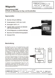
Windgeschwindigkeits- und Windrichtungsmesser - SCHRIEVER ...
Windgeschwindigkeits- und Windrichtungsmesser - SCHRIEVER ...
Windgeschwindigkeits- und Windrichtungsmesser - SCHRIEVER ...

Sie wollen auch ein ePaper? Erhöhen Sie die Reichweite Ihrer Titel.
YUMPU macht aus Druck-PDFs automatisch weboptimierte ePaper, die Google liebt.
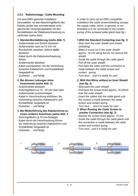
3.2.2 Kabelmontage / Cable Mounting<br />
Um eine EMV-gerechte Installation<br />
herzustellen, ist das Abschirmgeflecht des<br />
Kabels (außer das normalerweise nicht<br />
geschirmte Versorgungskabel) mit den<br />
Kontaktfedern der Kabelverschraubung zu<br />
verbinden (siehe Abb).<br />
1. Standardkontaktierung (siehe Abb. 1)<br />
- Außenmantel <strong>und</strong> Schirm absetzen<br />
- Außenmantel nach ca.15 mm mit<br />
R<strong>und</strong>schnitt versehen, jedoch nicht<br />
abziehen<br />
- Kabel durch die Kabelverschraubung<br />
führen<br />
- Außenmantel abziehen<br />
- Kabel zurückziehen, bis die Verbindung<br />
zwischen Kabelschirm <strong>und</strong> Kontaktfeder<br />
hergestellt ist<br />
- Zudrehen ... <strong>und</strong> fertig!<br />
2. Bei dünnen Leitungen ohne<br />
Innenmantel (siehe Abb. 2)<br />
- Außenmantel absetzen<br />
- Schirmgeflecht ca.15 - 20 mm über dem<br />
Außenmantel zurückschlagen<br />
- Kabel in Verschraubung einführen, bis<br />
Verbindung zwischen Kabelschirm <strong>und</strong><br />
Kontaktfeder hergestellt ist<br />
- Zudrehen ... <strong>und</strong> fertig!<br />
3. Bei Weiterführung des Kabelschirms zu<br />
einem anderen Anschluss (siehe Abb. 3<br />
- Schirmgeflecht ca.10 mm freilegen<br />
- Kabel durch die Verschraubung führen,<br />
bis Verbindung zwischen Kabelschirm <strong>und</strong><br />
Kontaktfeder hergestellt ist<br />
- Zudrehen ... <strong>und</strong> fertig!<br />
In order to carry out an EMC-compatible<br />
installation the cable screen/shielding (except<br />
the supply cable, which, in general, is not<br />
shielded) is to be connected to the contact<br />
spring of the screwed cable gland (see fig.)<br />
1.With the Standard Contacting (see fig. 1)<br />
- Strip back the outer sheath and screen<br />
(shielding)<br />
- Make a ro<strong>und</strong> cut in the outer sheath<br />
approx. 15 mm along but do not remove the<br />
sheath<br />
- Guide the cable through the cable gland<br />
- Pull off the outer sheath<br />
- Pull back the cable until the connection is<br />
made between the cable screen and<br />
contact spring<br />
- Turn shut… and it is ready for use!<br />
2. With thin Wires without an Inner Sheath<br />
(see fig. 2)<br />
- Strip back the outer sheath<br />
- Pull back the screen braid approx. 15-20mm<br />
over the outer sheath<br />
- Insert the cables into the cable gland until<br />
the contact is made between the cable<br />
screen and contact spring<br />
- Turn shut ….and it is ready for use!<br />
3. When Routing the Cable Screen to<br />
another Connection (see fig. 3)<br />
- Expose the screen braid approx. 10 mm<br />
- Guide the cable through the cable gland until<br />
the connection is made between the cable<br />
screen and contact spring<br />
- Turn shut…and it is ready for use!<br />
6 - 10 021437/11/08