CONTI SYNCHRODRIVE® Zahnriemen / Synchronous ... - ContiTech
CONTI SYNCHRODRIVE® Zahnriemen / Synchronous ... - ContiTech
CONTI SYNCHRODRIVE® Zahnriemen / Synchronous ... - ContiTech

Erfolgreiche ePaper selbst erstellen
Machen Sie aus Ihren PDF Publikationen ein blätterbares Flipbook mit unserer einzigartigen Google optimierten e-Paper Software.
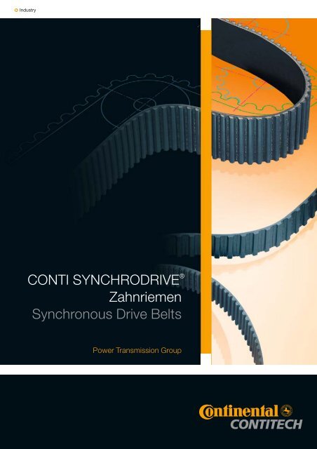
q Industry<strong>CONTI</strong> SYNCHRODRIVE ®<strong>Zahnriemen</strong><strong>Synchronous</strong> Drive BeltsPower Transmission Group
3–7 1 <strong>CONTI</strong> SYNCHRODRIVE ®<strong>Zahnriemen</strong>2–4 Eigenschaften4 Aufbau5 Bezeichnung6-7 Lieferprogramm7 Toleranzen1 <strong>CONTI</strong> SYNCHRODRIVE ®<strong>Synchronous</strong> Drive BeltsPropertiesConstructionDesignationProduct rangeTolerances9–18 2 Zahnscheiben10–11 Bezeichnung11 Mindest-Zähnezahl13–16 Durchmesser17 Toleranzen18 Spannplatten,Maße und Einspannlängen2 PulleysDesignationMinimum number of teethDiametersTolerancesClamps, dimensions andclamping lengths19–39 3 Berechnungvon <strong>Zahnriemen</strong>antrieben20–22 Formelzeichen, Einheiten, Begriffe22–23 Berechnungsunterlagen34–36 Berechnungsbeispiel, Hubantrieb37–39 Berechnungsbeispiel, Linearantrieb3 Calculationof <strong>Synchronous</strong> Belt DrivesGlossary of symbols and termsDrive calculation dataExample of design procedure steps:Lifting driveExample of design procedure steps:Linear drive40–44 StichwortverzeichnisIndex
Eigenschaften / PropertiesAufbau / ConstructionBezeichnung / DesignationLieferprogramm / Product rangeToleranzen / Tolerances1 <strong>CONTI</strong> SYNCHRODRIVE ®<strong>Zahnriemen</strong> / <strong>Synchronous</strong> drive belts
1 <strong>CONTI</strong> SYNCHRODRIVE ® <strong>Zahnriemen</strong> / <strong>Synchronous</strong> drive belts<strong>CONTI</strong> SYNCHRODRIVE ® <strong>Zahnriemen</strong> fürsynchrone Übertragung von Dreh- und Linearbewegungen<strong>CONTI</strong> SYNCHRODRIVE ® Belts for synchronoustransmission of rotary and linear motion<strong>CONTI</strong> SYNCHRODRIVE ® <strong>Zahnriemen</strong> sind Antriebselementeaus hochbeanspruchbarem Polyurethan-Elastomermit Stahlcordzugträger. Sie werden nach einemspeziell entwickelten Produktionsverfahren mit hoher Präzisionin endlicher Länge gefertigt.<strong>CONTI</strong> SYNCHRODRIVE ® <strong>Zahnriemen</strong> werden in endlicherAusführung oder auch endlos verschweißt eingesetzt.In allen Fällen übertragen sie Drehbewegungen winkelgenauund gleichförmig. <strong>CONTI</strong> SYNCHRODRIVE ®<strong>Zahnriemen</strong> ermöglichen wirtschaftliche Antriebslösungenauch bei schwierigen Bedingungen. Ihre Eigenschaftenergeben funktionsgerechte Antriebslösungen mit großerBetriebssicherheit und Wartungsfreiheit.<strong>CONTI</strong> SYNCHRODRIVE ® <strong>Zahnriemen</strong> werden in 10Zahnprofilen und mehreren Standardbreiten gefertigt. Damitdecken sie weite Einsatzgebiete mit unterschiedlichstenBelastungen und Bedingungen ab. BeispielhafteAnwendungen sind Antriebe mit großen Achsabständen,synchrone Fördersysteme und Transportvorrichtungenmit Gleitschienen und Positionier- und Reversierantriebein der Linear- und Steuertechnik. Moderne Fertigungsverfahrenund Qualitätsprüfungen in allen Verarbeitungsstufengewährleisten Produkte größter Zuverlässigkeit mitgleichbleibend hohem Qualitätsstandard.<strong>CONTI</strong> SYNCHRODRIVE ® belts are power transmissionproducts made from a highly durable polyurethane elastomerincorporating a steel-cord tension member. Theyare manufactured precisely to length using a newly developedproduction technique.<strong>CONTI</strong> SYNCHRODRIVE ® belts can be used in the openendedor endless form. In all cases, they ensure that rotarymotion is transmitted uniformly and with angular precision.<strong>CONTI</strong> SYNCHRODRIVE ® belts permit low-costdrive designs, even where difficult operating conditionshave to be taken into account. Their properties provide ahighly reliable, maintenance-free solution to even the mostdemanding drive problems.<strong>CONTI</strong> SYNCHRODRIVE ® belts are available in 10 toothprofiles and several standard widths, covering a host ofdifferent applications involving various loads and serviceconditions. They are ideal for drives with a large center distance,for synchronous conveyor systems and transportdevices with sliding rails as well as for positioning and reversingdrives in linear and control engineering. Modernproduction techniques and rigorous in-process qualitycontrols guarantee products with maximum reliability anda consistently high standard of quality.EigenschaftenExakte Synchronitätdurch formschlüssiges AntriebssystemWie bei einem Zahnradantrieb greifen die Zähne des Riemensdirekt in die Verzahnung der Antriebsscheiben. Dasformschlüssige Antriebsprinzip ergibt den synchronenLauf und eine jederzeit konstante Umfangsgeschwindigkeit.Vielseitige Anwendungsmöglichkeiten beigeringem konstruktivem Aufwand<strong>CONTI</strong> SYNCHRODRIVE ® <strong>Zahnriemen</strong> können in endlicheroder endloser Ausführung als synchrone Antriebs-oder Transportriemen eingesetzt werden. Fürbesondere Anwendungen lassen sich <strong>CONTI</strong> SYNCHRO-DRIVE ® <strong>Zahnriemen</strong> auch mit Steuer- oder Transportno-PropertiesPrecise synchronism due to positive engagementThe belt teeth mesh with those of the pulley in the samemanner as the teeth on a gear. This positive drive principleprovides synchronous operation and eliminates speedvariation.A variety of possible applications at low design cost<strong>CONTI</strong> SYNCHRODRIVE ® belts can be used as synchronousdrive or transport belts in either the open-ended orendless version. For special applications, <strong>CONTI</strong> SYN-CHRODRIVE ® belts can also be heavy-duty bonded tocams made from thermoplastics for control and transportfunctions. As open-ended drive components, <strong>CONTI</strong>SYNCHRODRIVE ® belts are ideal for linear and control drivesthat have to transmit rotary motion with repeat accuracyand multiple positioning control.2
cken aus Thermoplasten hochbeanspruchbar verschweißen.Als endliche Antriebselemente eignen sich <strong>CONTI</strong>SYNCHRODRIVE ® <strong>Zahnriemen</strong> hervorragend für LinearundSteuerantriebe, um Drehbewegungen positionierundwiederholgenau umzusetzen.Geringe Wellen- und LagerbelastungDas Verzahnungsprinzip erfordert nur eine geringe <strong>Zahnriemen</strong>vorspannung.Die Wellen- und Lagerbelastungenbleiben gering.Geringer RaumbedarfDie hohe dynamische Belastbarkeit und Flexibilität ermöglichendie Anwendung kleiner Zahnscheibendurchmesserund kurzer Wellenabstände sowie die Anordnungvon Rückenspannrollen. Damit können wirtschaftliche Antriebemit kleinem Bauvolumen und geringem Gewichtkonstruiert werden.Kein Wartungsaufwand<strong>CONTI</strong> SYNCHRODRIVE ® <strong>Zahnriemen</strong> sind wartungsfrei.Schmieren und Nachspannen sind nicht erforderlich.Durch die Verwendung von Stahlcordzugträgern hoherFestigkeit ist nach einer kurzen Einlaufphase eine konstanteRiemenspannung gewährleistet.Hoher WirkungsgradDie flexible und biegetüchtige <strong>Zahnriemen</strong>ausführungsowie die gute maßliche Abstimmung der Zahnkonturvon Riemen und Zahnscheiben ermöglichen Antriebe miteinem Wirkungsgrad von 98%. .<strong>CONTI</strong> SYNCHRODRIVE ® <strong>Zahnriemen</strong> sindq abriebfestq öl- und fettbeständigq benzin- und benzolbeständigq hydrolysebeständigq UV- und ozonbeständigq temperaturbeständig von – 30 bis 80 °C,(bitte fordern Sie im Bereich unter –10 °C undüber 50 °C technische Beratung an)q verschweißbar mit ThermoplastenLow loads on shafts and bearingsThe tooth grip principle requires only low initial belt tensioning.Thus the load on shafts and bearings is kept to aminimum.Compact drive designHigh dynamic stability and flexibility allows the use of smallpulley diameters, low center distances, and backside idlers.This enables a lightweight, low-cost drive setup withless space requirement.No maintenance<strong>CONTI</strong> SYNCHRODRIVE ® belts are maintenance-free; nolubrication or retensioning is required. Constant belt tensionis guaranteed by the use of a high-strength steel-cordtension member.High efficiencyThe superb flexural properties of the synchronous drivebelt as well as the exact dimensional mating of the beltand pulley tooth contours permit drives with an efficiencyof 98%.<strong>CONTI</strong> SYNCHRODRIVE ® belts are resistant toq wearq oil and greaseq petrol and benzeneq hydrolysisq UV and ozoneq temperatures ranging from – 30°Cto +80°C(for operational temperatures outside –10 °C to50 °C please seek advice from our technical experts)q can be bonded to thermoplastics3
1 <strong>CONTI</strong> SYNCHRODRIVE ® <strong>Zahnriemen</strong> / <strong>Synchronous</strong> drive beltsAusführungen<strong>CONTI</strong> SYNCHRODRIVE ® <strong>Zahnriemen</strong> werden in folgendenAusführungen geliefert:HF q flexible Ausführung,alle Profile außer 3 mm Teilungz.B. für Antriebe mit kleinenScheibendurchmessernHP q verstärkte AusführungProfile HTD und STDz.B. für Steuerungssystememit hoher BelastungHS q hohe ZugträgersteifigkeitProfile HTD und STDz.B. für hochpräzise LinearantriebeXHP q extra hohe ZugfestigkeitProfil HTD 14Mz.B. für HubsystemePAZ q Gewebearmierung auf der Zahnseite, z.B. fürTransportvorrichtungen mit Gleitschienen.Antistatische Ausführung aPAZ auf Anfrage.PAR q Gewebearmierung auf dem Riemenrückenz.B. für Stauförderer. Antistatische AusführungaPAR auf Anfrage.V q endlos verschweißte <strong>Zahnriemen</strong>in Ausführung HF und Längen ab 1000 mm, alleProfile außer 3 mm Teilungz.B. für Rotationsantriebe mit großenAchsabständenWeitere Sonderausführungen auf Anfrage.Belt versions<strong>CONTI</strong> SYNCHRODRIVE ® belts are supplied in thefollowing versions:HF q high flexible versionall profiles except for 3 mm pitche.g. for drives with small pulley diametersHP q high power reinforced versionHTD and STD profilese.g. for heavy-duty control systemsHS q high stiffness of tension memberHTD and STD profilese.g. for high-precision linear drivesXHP q extremely high power tensile-strengthHTD 14M profilee.g. for lifting systemsPAZ q with polyamide fabric facing on the pulley sidee.g. for sliding-rail transport systems.Antistatic aPAZ version on request.PAR q with polyamide fabric facing on the back ofthe belt e.g. for skid-queuing conveyors.Antistatic aPAR version on request.V q endless belt in HF version and lengths from1000 mm, all profiles except for 3 mm pitche.g. for rotary drives with large center distancesOther special versions can be supplied on request.AufbauConstructionPolyurethan-RiemenrückenStahlcordzugträgerPolyurethan-ZähneOptional:Gewebearmierungzahn-/rückenseitigPolyurethane belt backingSteel-cord tension memberPolyurethane teethOptional:Fabric facing in the pulleyside/back of the beltDie Elemente des <strong>Zahnriemen</strong>s sind:q Polyurethan-Zähne und -Riemenrücken,Farbe: schwarzq Stahlcordzugträger,Schlagrichtungen zueinander balanciertPolyurethan-Zähne und -RiemenrückenHochbeanspruchbares Polyurethan-Elastomer bildetZähne und Riemenrücken mit einer hervorragenden Bindungzum Zugträger. Die hohe Abriebfestigkeit des Polyurethansist die Voraussetzung für störungsfreien Antriebund lange Lebensdauer. Dieses wird unterstützt durch diebalancierte Zugträgeranordnung.Our synchronous drive belts are made up ofq polyurethane teeth and backing,color: blackq steel-cord tension member,with balanced right/left-handed cord twistPolyurethane teeth and backingBelt teeth and backing are made from a tough polyurethaneelastomer with excellent adhesion to the tensionmember. The high wear resistance of the polyurethaneensures trouble-free drive performance and a longservice life. These features are enhanced even more bythe balanced layout of the tension cords.4
Stahlcordzugträger<strong>Zahnriemen</strong> für formschlüssige Antriebssysteme erforderneine hohe Längenkonstanz und Zugfestigkeit. Kantenparallelangeordnete Stahlcordzugträger hoher Festigkeitgewährleisten große Belastbarkeit der <strong>Zahnriemen</strong>und exaktes Laufverhalten.Steel-cord tension member<strong>Synchronous</strong> drive belts for positive drive systems musthave a high resistance to elongation and a high tensilestrength. Extra-strong steel tension cords, laid parallel tothe belt edges, guarantee the belt’s high loading capacityand accurate running properties.Bezeichnung<strong>CONTI</strong> SYNCHRODRIVE ® <strong>Zahnriemen</strong> werden nach denfür die unterschiedlichen Riementypen festgelegtenStandards mit Wirklänge, Zahnteilung und <strong>Zahnriemen</strong>breitebezeichnet, ergänzt durch Kurzzeichen für die Ausführung,siehe Seite 4.q Wirklänge in mDie Wirklänge des <strong>Zahnriemen</strong>s ist der Gesamtumfang,gemessen auf der biegeneutralen Wirklinie. Die Wirklängeliegt in der Mitte des Zugträgers.q Zahnteilung in mm oder InchDie Zahnteilung ist der lineare Abstand zwischen zwei benachbartenZähnen in Höhe der Wirklinie.q <strong>Zahnriemen</strong>breite in mm oder 1/100 InchDie <strong>Zahnriemen</strong>breite und die Breitenbezeichnung sindidentisch.BeispieleDesignation<strong>CONTI</strong> SYNCHRODRIVE ® synchronous drive belts arespecified in accordance with defined standards for the differentbelt types showing the pitch length, tooth pitch andbelt width, plus a code for the belt version, see page 4.q Pitch length in mThe pitch length of the belt is the overall circumference, orlength measuredat the neutral pitch line. The pitch lengthis located in the middle of thetension member.q Tooth pitch in mm or inchesThe tooth pitch is the linear distance between two adjacentteeth at the pitch line.q Belt width in mm or hundredths of an inchThe belt width and width designation are identical.Examples<strong>CONTI</strong> SYNCHRODRIVE ® HTD <strong>Zahnriemen</strong> / <strong>Synchronous</strong> drive belts – M 30 – 8M – 50 HPMendliche Ausführung30 30 m Wirklänge8M8 mm Zahnteilung, Profil HTD50 50 mm <strong>Zahnriemen</strong>breiteHPverstärkte AusführungMopen-ended type30 pitch length 30 m8Mtooth pitch 8 mm , HTD profile50 belt width 50 mmHPreinforced version<strong>CONTI</strong> SYNCHRODRIVE ® STD <strong>Zahnriemen</strong> / <strong>Synchronous</strong> drive belts – V 2400 – S 5M – 30 HFVendlos verschweißte Ausführung2400 2400 mm RiemenlängeS 5M5 mm Zahnteilung, Profil STD30 30 mm <strong>Zahnriemen</strong>breiteHFflexible AusführungVendless type2400 belt length 2400 mmS 5Mtooth pitch 5 mm, STD profile30 belt width 30 mmHFflexible version<strong>CONTI</strong> SYNCHRODRIVE ® <strong>Zahnriemen</strong> / <strong>Synchronous</strong> drive belts – 10 x M 30 H 100 PAZ10 Anzahl der RollenMendliche Ausführung30 30 m WirklängeH0,5 Inch = 12,7 mm Zahnteilung100 1,0 Inch = 25,4 mm <strong>Zahnriemen</strong>breitePAZLaufseite mit GewebearmierungDie Zähnezahl ergibt sich aus Wirklänge und Teilung:10 number of rollsMopen-ended type30 pitch length 30 mHtooth pitch 0.5 Inch = 12.7 mm100 belt width 1.0 Inch = 25.4 mmPAZwith fabric facing on the pulley sideThe number of teeth is a function of pitch length and pitch:z L wt5
1 <strong>CONTI</strong> SYNCHRODRIVE ® <strong>Zahnriemen</strong> / <strong>Synchronous</strong> drive beltsLieferprogrammProfile<strong>CONTI</strong> SYNCHRODRIVE ® <strong>Zahnriemen</strong> werden in 10 Profilgrößengefertigt. Die Maße der HTD- und STD-<strong>Zahnriemen</strong>entsprechen dem Entwurf ISO/F DIS 13050, die der Trapez-<strong>Zahnriemen</strong>DIN ISO 5296. In Tabelle 1 (Seite 6) sinddie Profilmaße und weitere technische Angaben der lieferbaren<strong>Zahnriemen</strong> zusammengefaßt. Bei Linearantriebenmit besonders hohen Genauigkeitsanforderungen ist dieVerwendung von Sonderzahnscheiben erforderlich.Weitere Angaben zu den Scheiben enthält das KapitelZahnscheiben auf Seite 10.Längen<strong>CONTI</strong> SYNCHRODRIVE ® <strong>Zahnriemen</strong> können in endlicheroder endloser Ausführung eingesetzt werden.Breiten<strong>CONTI</strong> SYNCHRODRIVE ® <strong>Zahnriemen</strong> werden in mehrerenStandardbreiten geliefert. Die Maße sind in Tabelle 2(Seite 7) aufgeführt. Abweichende Breiten auf Anfrage.Ausführungen<strong>CONTI</strong> SYNCHRODRIVE ® <strong>Zahnriemen</strong> aus Polyurethanmit kantenparallel angeordnetem Stahlcordzuträger sindPräzisionselemente für Anwendungen im Bereich der Antriebs-und Transporttechnik. Für spezielle Anforderungensind <strong>Zahnriemen</strong> in unterschiedlichen Ausführungen lieferbar.Erläuterungen siehe Abschnitt „Eigenschaften”,Seiten 2 bis 4.Product rangeProfiles<strong>CONTI</strong> SYNCHRODRIVE ® belts are manufactured in 10profile sizes. Dimensions of HTD and STD synchronousdrive belts correspond to the specifications laid down inISO/F DIS 13050 (draft version) and those of trapezoidalbelts comply with DIN ISO 5296. Table 1 on page 6 givesa summary of the profile dimensions as well as other technicalinformation for the belts we supply. Special pulleysmust be used for linear drives with high precision requirements.Moreinformation about pulleys is given in section2 on “Pulleys“ which starts on page 10.Lengths<strong>CONTI</strong> SYNCHRODRIVE ® belts are available in either theopen-ended or endless version.Widths<strong>CONTI</strong> SYNCHRODRIVE ® belts are supplied in severalstandard widths. Dimensions are given in Table 2 onpage 7. Other widths are available on request.Versions<strong>CONTI</strong> SYNCHRODRIVE ® belts made from polyurethanewith steel cords aligned parallel to the belt edges are precision-madecomponents for applications in drive andtransportation engineering. Several versions are availableto meet various operating requirements. More details aregiven on pages 2 to 4 under “Properties“.Abb. / Fig. 1 Zahnprofil / Tooth profile Zahnprofil / Tooth profile Zahnprofil / Tooth profileHTD 3M, HTD 5M, STD S 5M, STD S 8M, XL, L, HHTD 8M, HTD 14MSTD S 3M auf Anfrage / on requestTab. 1Kenndaten / SpecificationsZahnprofil Tooth profile HTD STD Trapez3M 5M 8M 14M S 3M S 5M S 8M XL L HZahnteilung t Tooth pitch t mm 3,00 5,00 8,00 14,00 3,00 5,00 8,00 5,080 9,525 12,700Inch 0,200 0,375 0,500Riemendicke h s Belt thickness h s mm 2,4 3,60 5,60 10,00 2,30 3,40 5,20 2,30 3,60 04,30Zahnhöhe h t Tooth height h t mm 1,3 2,10 3,40 6,10 1,14 1,90 3,00 1,27 1,91 02,29Gewicht m spez Weight m spezpro mm Riemenbreite per mm of belt widthAusführung HF Type HF 10 –3 kg/m 3,36 5,40 10,37 3,21 5,24 2,16 3,65 04,53HP HP 10 –3 kg/m 3,15 4,06 6,32 11,27 3,08 3,91 6,22HS HS 10 –3 kg/m 7,22 11,40 4,64 7,12XHP XHP 10 –3 kg/m 14,00Standardlänge StandardAusführung M L w Type M L w m 30 bzw. / or 606
<strong>Zahnriemen</strong>breite / Belt width – b in mm Tab. 2Zahnprofil Tooth profile HTD STD Trapez3M 5M 8M 14M S 3M S 5M S 8M XL L HWeitere Zwischenbreiten auf Anfrage / Other inermedia widths on request5 5 5 5 6,3510 10 10 10 10 10 9,53 9,5315 15 15 15 15 15 12,70 12,70 12,7020 20 19,05 19,05 19,0525 25 25 25 25 25,40 25,4030 3040 38,10 38,1050 50 50 50/55 50 50 50 50,80 50,80 50,8085 85 85100 100 100115120Toleranzen<strong>CONTI</strong> SYNCHRODRIVE ® <strong>Zahnriemen</strong> sind Präzisionserzeugnisse.Ihre Fertigung erfolgt prozesssicher mit hoherGenauigkeit. Die Abweichungen für Länge, Breite undDicke sind äußerst eng toleriert.Tolerances<strong>CONTI</strong> SYNCHRODRIVE ® belts are precision-made products.Manufacturing involves reliable process techniquesand maximum accuracy throughout all stages. Deviationsin length, width and thickness are subject to extremelytight tolerances.Toleranzen für <strong>Zahnriemen</strong>längen / Belt length tolerances Tab. 3Wirklänge / Pitch length L w mm Längentoleranz / Length tolerance %L w 0,1Toleranzen für <strong>Zahnriemen</strong>breiten / Belt width tolerances Tab. 4Zahnprofil Tooth profile HTD STD Trapez3M 5M 8M 14M S 3M S 5M S 8M XL L HRiemenbreite b Belt width b bis 25 mm 0,5 0,5 0,6 0,6 0,5 0,5 0,6 0,5 0,6 0,625–50 mm 0,6 0,6 0,7 1,0 0,6 0,6 0,7 0,6 0,7 0,750 mm 0,8 1,2 0,8 0,8 0,8Toleranzen für <strong>Zahnriemen</strong>dicken (Ausführung M) / Belt thickness tolerances (Type M) Tab. 5Zahnprofil Tooth profile HTD STD Trapez3M 5M 8M 14M S 3M S 5M S 8M XL L HRiemendicke h s Belt thickness h s mm 2,4 3,6 5,6 10,0 2,3 3,4 5,2 2,3 3,6 4,3Dickentoleranz Thickness tolerance mm 0,25 0,25 0,4 0,6 0,25 0,25 0,4 0,25 0,4 0,47
Bezeichnung /DesignationMindest-Zähnezahl / Minimum number of teethDurchmesser / DiametersToleranzen / TolerancesEinspannlänge / Clamping length2 Zahnscheiben / Pulleys9
2 Zahnscheiben / PulleysZahnscheibenPulleysDie Übertragungsgenauigkeit, die Laufruhe und die Lebensdauervon <strong>Zahnriemen</strong>antrieben werden entscheidendvom präzisen Zusammenwirken von Riemen undZahnscheibe bestimmt.Die von <strong>ContiTech</strong> weiterentwickelten Zahnlückenprofileder Zahnscheiben sind den jeweiligen Riemenprofilen idealangepasst.Speziell für <strong>CONTI</strong> SYNCHRODRIVE ® HTD <strong>Zahnriemen</strong>ist der Einsatz dieser optimierten Zahnscheiben zu empfehlen.Zahnscheiben mit den optimierten Profilen liefert derFachhandel.Für Linearantriebe mit sehr hohen Positionier-Anforderungensind Zahnscheiben mit minimiertem Lückenspiel erforderlich.Bei Sonderausführungen bitte anwendungstechnischeBeratung anfordern.BezeichnungZahnscheiben für <strong>CONTI</strong> SYNCHRODRIVE ® <strong>Zahnriemen</strong>antriebewerden nach den für die unterschiedlichen <strong>Zahnriemen</strong>typenfestgelegten Standards mit Zähnezahl,Zahnteilung und Zahnscheibenbreite sowie Kurzzeichenfür die Ausführung bezeichnet.q PAllgemeine Bezeichnung für Zahnscheiben.q ZähnezahlDie Zähnezahl der Zahnscheibe errechnet sich aus Wirkumfangund Teilung:Precise belt/pulley conformance is vital to ensure accuratepower transmission as well as smooth operation anda long service life for synchronous belt drives.<strong>ContiTech</strong> engineers have modified pulley tooth-gapprofiles so that they conform ideally to the respective beltprofilesUse of these optimized pulleys is recommended especiallyfor <strong>CONTI</strong> SYNCHRODRIVE ® HTD belts.Pulleys with optimized profiles are obtainable from your localpulley supplier.Linear drives with demanding positioning requirementsneed pulleys with minimized gap clearance. If you areplanning a special drive design, please consult our applicationengineers for advice.DesignationPulleys for <strong>CONTI</strong> SYNCHRODRIVE ® belt drives are identifiedin accordance with the standards defined for the variousbelt types by their number of teeth, tooth pitch andpulley width, as well as a code denoting the type of pulley.q PGeneral designation for toothed pulleys.q Number of teethThe pulley’s number of teeth is calculated from the pitchcircumference and the pitch:Uz w · d wt tq Zahnteilung in mm oder InchDie Zahnteilung der Zahnscheibe ist der Abstand zwischenzwei Bezugspunkten benachbarter Zähne auf demUmfang des Wirkdurchmessers. Der Wirkdurchmesser istum den doppelten Betrag des Wirklinienabstandes deszugehörigen <strong>Zahnriemen</strong>s größer als der Zahnscheiben-Außendurchmesser und liegt in der Höhe der Wirklinie des<strong>Zahnriemen</strong>s.q Zahnscheibenbreite in mm oder 1/100 InchDie Breitenbezeichnung gibt die genaue Breite des zugehörigen<strong>Zahnriemen</strong>s, nicht aber die genaue Scheibenbreitean.q Angaben für BordscheibenF bedeutet beidseitig Bordscheiben.Bordscheiben verhindern das Ablaufen von <strong>Zahnriemen</strong>.Es ist erforderlich, mindestens eine Zahnscheibe mit 2Bordscheiben zu versehen. Aus Kostengründen solltehierfür die kleinere Zahnscheibe gewählt werden. Auchdas wechselseitige Anbringen von je 1 Bordscheibe proZahnscheibe ist möglich.q Tooth pitch in mm or inchesThe tooth pitch of the pulley is the distance between tworeference points on adjacent teeth at the circumference ofthe pitch diameter. The pitch diameter is larger than theoutside diameter of the pulley by double the thickness atwhich the pitch line of belt rides above the pulley.q Pulley width in mm or hundredths of an inchThe width designation defines the exact width of the correspondingsynchronous drive belt, and not that of thepulley.q Flanged pulley dataF stands for pulleys that are flanged on both sides.Flanged pulleys prevent the belt from riding off. At leastone pulley with two flanges must be used and generally,for economy, the smaller pulley of a drive is the flangedpulley. It is also possible to provide each pulley with oneflange on alternate sides.10
BeispieleHTD Zahnscheibe / Pulley – P 36 – 8M – 40PZahnscheibe36 36 Zähne8M8 mm Zahnteilung, Profil HTD40 Zahnscheibe für 40 mm breite <strong>Zahnriemen</strong>ExamplesPDesignation for toothed pulley36 36 teeth8M8 mm tooth pitch, HTD profile40 Pulley designation for a 40 mm widesynchronous drive beltSTD Zahnscheibe / Pulley – P 48 – S 5M – 30PZahnscheibe48 48 ZähneS 5M5 mm Zahnteilung, Profil STD30 Zahnscheibe für 30 mm breite <strong>Zahnriemen</strong>PDesignation for toothed pulley48 48 teethS 5M5mm tooth pitch, STD profile30 Pulley designation for a 30 mm widesynchronous drive beltZahnscheibe / Pulley – P 48 H 100 FPZahnscheibe48 48 ZähneHZahnteilung 0,5 Inch = 12,7 mm100 Zahnscheibe für 25,4 mm breite <strong>Zahnriemen</strong>Fbeidseitig BordscheibenPDesignation for toothed pulley48 48 teethHTooth pitch 0.5 inch = 12.7 mm100 Pulley designation for a 25.4 mm widesynchronous drive beltFPulley flanged on both sidesMindest-ZähnezahlFür Antriebe mit <strong>CONTI</strong> SYNCHRODRIVE ® <strong>Zahnriemen</strong> solltenMindest-Zähnezahlen nicht unterschritten werden. DieMindest-Zähnezahl z min und der Mindest-Wirkdurchmesserd w min für Zahnscheiben sowie die Mindest-Durchmesserd min für Innen- und Außenspannrollen, die bei der Auslegungeines Antriebes zu berücksichtigen sind, enthältTabelle 6. Innenspannrollen sollten als Zahnscheiben ausgeführtwerden.Minimum number of teethDrives fitted with <strong>CONTI</strong> SYNCHRODRIVE ® belts shouldhave pulleys that meet the specified minimum number ofteeth. Table 6 shows the minimum number of teeth z min andthe minimum pitch diameter d w min for pulleys as well as theminimum diameter dmin for inside and outside idlers that areto be considered when designing a drive. Inside idlersshould be pulleys.Mindest-Zähnezahl / Minimum number of teeth – z min Tab. 6Zahnprofil / Tooth profile HTD STD Trapez3M 5M 8M 14M S 3M S 5M S 8M XL L HMindest-ZähnezahI / Minimum number of teeth z minAusführung / Type HF 12 16 18 12 16 10 12 14HP 20 16 20 26 20 16 20HS 28 30 24 28XHP 34Mindest-Wirkdurchmesser / Minimum pitch Ø d w minAusführung / Type HF mm 19,10 40,74 80,21 19,10 40,74 16,17 36,38 56,60HP mm 19,10 25,46 50,93 115,86 19,10 25,46 50,93HS mm 71,30 133,69 38,20 71,30XHP mm 151,52Mindest-Spannrollendurchmesser / Minimum Ø of idler d minAusführung / Type HF innen / inside mm 19,10 40,74 80,21 19,10 40,74 19,40 39,41 60,64außen / outside mm 30,00 60,00 120,00 30,00 60,00 30,00 60,00 90,00HP innen / inside mm 19,10 25,46 50,93 115,86 19,10 25,46 50,93außen / outside mm 30,00 50,00 100,00 160,00 30,00 50,00 100,00HS innen / inside mm 71,30 133,69 44,56 71,30außen / outside mm 120,00 180,00 80,00 120,00XHP innen / inside mm 151,52außen / outside mm 200,00Scheibendurchmesser für Ausführung V, Einbausituation Omega: Bitte Beratung anfordern.Minimum diameter Belt version V with omega pulley configuration: please call for technical support.11
2 Zahnscheiben / PulleysDurchmesserZähnezahlen, Wirk- und Außendurchmesser von Zahnscheibenfür Antriebe mit <strong>CONTI</strong> SYNCHRODRIVE ®<strong>Zahnriemen</strong> sind in den Tabellen 7 bis 16 (Seiten 12 bis 16)aufgeführt.DiametersNumber of teeth, pitch and outside diameter of pulleysfor drives fitted with <strong>CONTI</strong> SYNCHRODRIVE ® belts arecontained in Tables 7 to 16 on pages 12 to 16.Tab. 7Zahnscheiben für / Pulleys for <strong>CONTI</strong> SYNCHRODRIVE ® HTD <strong>Zahnriemen</strong> / synchronous drive beltsZahnteilung 3 mm, Profil 3M (Maße in mm) / 3 mm tooth pitch, 3M profile (measurement in mm)Zähne- Wirk- AußenzahlZähne- Wirk- Außen-Zähne- Wirk- Außen-Zähne- Wirk- Außenzahlz d w d a z d w d a z d w d a z d w d aØ ØØ Ø zahl Ø Ø zahl Ø ØNumber of Pitch Outside Number of Pitch Outside Number of Pitch Outside Number of Pitch Outsideteeth diameter diameter teeth diameter diameter teeth diameter diameter teeth diameter diameter20 19,10 18,34 35 33,42 32,66 50 47,75 46,99 65 62,07 61,3121 20,05 19,29 36 34,38 33,62 51 48,70 47,94 66 63,03 62,2722 21,01 20,25 37 35,33 34,57 52 49,66 48,90 67 63,98 63,2223 21,96 21,20 38 36,29 35,53 53 50,61 49,85 68 64,94 64,1824 22,92 22,16 39 37,24 36,48 54 51,57 50,81 69 65,89 65,1325 23,87 23,11 40 38,20 37,44 55 52,52 51,75 70 66,85 66,0926 24,83 24,07 41 39,15 38,39 56 53,48 52,72 71 67,80 67,0427 25,78 25,02 42 40,11 39,35 57 54,43 53,67 72 68,75 67,9928 26,74 25,98 43 41,06 40,30 58 55,39 54,6329 27,69 26,93 44 42,02 41,26 59 56,34 55,5830 28,65 27,89 45 42,97 42,21 60 57,30 56,5431 29,60 28,84 46 43,93 43,17 61 58,25 57,4932 30,56 29,80 47 44,88 44,12 62 59,21 58,4533 31,51 30,75 48 45,84 45,08 63 60,16 59,4034 32,47 31,71 49 46,79 46,03 64 61,12 60,36Tab. 8Zahnscheiben für / Pulleys for <strong>CONTI</strong> SYNCHRODRIVE ® HTD <strong>Zahnriemen</strong> / synchronous drive beltsZahnteilung 5 mm, Profil 5M (Maße in mm) / 5 mm tooth pitch, 5M profile (measurement in mm)Zähne- Wirk- AußenzahlZähne- Wirk- Außen-Zähne- Wirk- Außen-Zähne- Wirk- Außenzahlz d w d a z d w d a z d w d a z d w d aØ ØØ Ø zahl Ø Ø zahl Ø ØNumber of Pitch Outside Number of Pitch Outside Number of Pitch Outside Number of Pitch Outsideteeth diameter diameter teeth diameter diameter teeth diameter diameter teeth diameter diameter12 19,10 17,96 28 44,56 43,42 44 70,03 68,89 60 95,49 94,3513 20,69 19,55 29 46,15 45,01 45 71,62 70,48 61 97,08 95,9414 22,28 21,14 30 47,75 46,61 46 73,21 72,07 62 98,68 97,5415 23,87 22,73 31 49,34 48,20 47 74,80 73,66 63 100,27 99,1316 25,46 24,32 32 50,93 49,79 48 76,39 75,25 64 101,86 100,7217 27,06 25,92 33 52,52 51,38 49 77,99 76,85 65 103,45 102,3118 28,65 27,51 34 54,11 52,97 50 79,58 78,44 66 105,04 103,9019 30,24 29,10 35 55,70 54,56 51 81,17 80,03 67 106,63 105,4920 31,83 30,69 36 57,30 56,16 52 82,76 81,62 68 108,23 107,0921 33,42 32,28 37 58,89 57,75 53 84,35 83,21 69 109,82 108,6822 35,01 33,87 38 60,48 59,34 54 85,94 84,80 70 111,41 110,2723 36,61 35,47 39 62,07 60,93 55 87,54 86,40 71 113,00 111,8624 38,20 37,06 40 63,66 62,52 56 89,13 87,99 72 114,59 113,4525 39,79 38,65 41 65,25 64,11 57 90,72 89,5826 41,38 40,24 42 66,85 65,71 58 92,31 91,1727 42,97 41,83 43 68,44 67,30 59 93,90 92,7612
Zahnscheiben für / Pulleys for <strong>CONTI</strong> SYNCHRODRIVE ® HTD <strong>Zahnriemen</strong> / synchronous drive beltsTab. 9Zahnteilung 8 mm, Profil 8M (Maße in mm) / 8 mm tooth pitch, 8M profile (measurement in mm)Zähne- Wirk- AußenzahlZähne- Wirk- Außen-Zähne- Wirk- Außen-Zähne- Wirk- Außenzahlz d w d a z d w d a z d w d a z d w d aØ ØØ Ø zahl Ø Ø zahl Ø ØNumber of Pitch Outside Number of Pitch Outside Number of Pitch Outside Number of Pitch Outsideteeth diameter diameter teeth diameter diameter teeth diameter diameter teeth diameter diameter16 40,74 39,37 31 78,94 77,57 46 117,14 115,77 61 155,34 153,9717 43,29 41,92 32 81,49 80,12 47 119,68 118,31 62 157,88 156,5118 45,84 44,47 33 84,03 82,66 48 122,23 120,86 63 160,43 159,0619 48,38 47,01 34 86,58 85,21 49 124,78 123,41 64 162,97 161,6020 50,93 49,56 35 89,13 87,76 50 127,32 125,95 65 165,52 164,1521 53,48 52,11 36 91,67 90,30 51 129,87 128,50 66 168,07 166,7022 56,02 54,65 37 94,22 92,85 52 132,42 131,05 67 170,61 169,2423 58,57 57,20 38 96,77 95,40 53 134,96 133,59 68 173,16 171,7924 61,12 59,75 39 99,31 97,94 54 137,51 136,14 69 175,71 174,3425 63,66 62,29 40 101,86 100,49 55 140,06 138,69 70 178,25 176,8826 66,21 64,84 41 104,41 103,04 56 142,60 141,23 71 180,80 179,4327 68,75 67,38 42 106,95 105,58 57 145,15 143,78 72 183,35 181,9828 71,30 69,93 43 109,50 108,13 58 147,70 146,3329 73,85 72,48 44 112,05 110,68 59 150,24 148,8730 76,39 75,02 45 114,59 113,22 60 152,79 151,42Zahnscheiben für / Pulleys for <strong>CONTI</strong> SYNCHRODRIVE ® HTD <strong>Zahnriemen</strong> / synchronous drive beltsTab. 10Zahnteilung 14 mm, Profil 14M (Maße in mm) / 14 mm tooth pitch, 14M profile (measurement in mm)Zähne- Wirk- AußenzahlZähne- Wirk- Außen-Zähne- Wirk- Außen-Zähne- Wirk- Außenzahlz d w d a z d w d a z d w d a z d w d aØ ØØ Ø zahl Ø Ø zahl Ø ØNumber of Pitch Outside Number of Pitch Outside Number of Pitch Outside Number of Pitch Outsideteeth diameter diameter teeth diameter diameter teeth diameter diameter teeth diameter diameter18 80,21 77,41 33 147,06 144,26 48 213,90 211,10 63 280,75 277,9519 84,67 81,87 34 151,52 148,71 49 218,36 215,56 64 285,20 282,4020 89,13 86,33 35 155,97 153,17 50 222,82 220,02 65 289,66 286,8621 93,58 90,78 36 160,43 157,63 51 227,27 224,47 66 294,12 291,3222 98,04 95,24 37 164,88 162,08 52 231,73 228,93 67 298,57 295,7723 102,50 99,70 38 169,34 166,54 53 236,18 233,38 68 303,03 300,2324 106,95 104,15 39 173,80 171,00 54 240,64 237,84 69 307,48 304,6825 111,41 108,61 40 178,25 175,45 55 245,10 242,30 70 311,94 309,1426 115,86 113,06 41 182,71 179,91 56 249,55 246,75 71 316,40 313,6027 120,32 117,52 42 187,16 184,36 57 254,01 251,21 72 320,85 318,0528 124,78 121,98 43 191,62 188,82 58 258,47 255,6729 129,23 126,43 44 196,08 193,28 59 262,92 260,1230 133,69 130,89 45 200,53 197,73 60 267,38 264,5831 138,15 135,35 46 204,99 202,19 61 271,83 269,0332 142,50 139,80 47 209,45 206,65 62 276,29 273,4913
2 Zahnscheiben / PulleysTab. 11Zahnscheiben für / Pulleys for <strong>CONTI</strong> SYNCHRODRIVE ® STD <strong>Zahnriemen</strong> / synchronous drive beltsZahnteilung 3 mm, Profil S 3M (Maße in mm) / 3 mm tooth pitch, S 3M profile (measurement in mm)Zähne- Wirk- AußenzahlZähne- Wirk- Außen-Zähne- Wirk- Außen-Zähne- Wirk- Außenzahlz d w d a z d w d a z d w d a z d w d aØ ØØ Ø zahl Ø Ø zahl Ø ØNumber of Pitch Outside Number of Pitch Outside Number of Pitch Outside Number of Pitch Outsideteeth diameter diameter teeth diameter diameter teeth diameter diameter teeth diameter diameter20 19,10 18,34 35 33,42 32,66 50 47,75 46,99 65 62,07 61,3121 20,05 19,29 36 34,38 33,62 51 48,70 47,94 66 63,03 62,2722 21,01 20,25 37 35,33 34,57 52 49,66 48,90 67 63,98 63,2223 21,96 21,20 38 36,29 35,53 53 50,61 49,85 68 64,94 64,1824 22,92 22,16 39 37,24 36,48 54 51,57 50,81 69 65,89 65,1325 23,87 23,11 40 38,20 37,44 55 52,52 51,75 70 66,85 66,0926 24,83 24,07 41 39,15 38,39 56 53,48 52,72 71 67,80 67,0427 25,78 25,02 42 40,11 39,35 57 54,43 53,67 72 68,75 67,9928 26,74 25,98 43 41,06 40,30 58 55,39 54,6329 27,69 26,93 44 42,02 41,26 59 56,34 55,5830 28,65 27,89 45 42,97 42,21 60 57,30 56,5431 29,60 28,84 46 43,93 43,17 61 58,25 57,4932 30,56 29,80 47 44,88 44,12 62 59,21 58,4533 31,51 30,75 48 45,84 45,08 63 60,16 59,4034 32,47 31,71 49 46,79 46,03 64 61,12 60,36Tab. 12Zahnscheiben für / Pulleys for <strong>CONTI</strong> SYNCHRODRIVE ® STD <strong>Zahnriemen</strong> / synchronous drive beltsZahnteilung 5 mm, Profil S 5M (Maße in mm) / 5 mm tooth pitch, S 5M profile (measurement in mm)Zähne- Wirk- AußenzahlZähne- Wirk- Außen-Zähne- Wirk- Außen-Zähne- Wirk- Außenzahlz d w d a z d w d a z d w d a z d w d aØ ØØ Ø zahl Ø Ø zahl Ø ØNumber of Pitch Outside Number of Pitch Outside Number of Pitch Outside Number of Pitch Outsideteeth diameter diameter teeth diameter diameter teeth diameter diameter teeth diameter diameter12 19,10 18,14 28 44,56 43,60 44 70,03 69,07 60 95,49 94,5313 20,69 19,73 29 46,15 45,19 45 71,62 70,66 61 97,08 96,1214 22,28 21,32 30 47,75 46,79 46 73,21 72,25 62 98,68 97,7215 23,87 22,91 31 49,34 48,38 47 74,80 73,84 63 100,27 99,3116 25,46 24,50 32 50,93 49,97 48 76,39 75,43 64 101,86 100,9017 27,06 26,10 33 52,52 51,56 49 77,99 77,03 65 103,45 102,4918 28,65 27,69 34 54,11 53,15 50 79,58 78,62 66 105,04 104,0819 30,24 29,28 35 55,70 54,74 51 81,17 80,21 67 106,63 105,6720 31,83 30,87 36 57,30 56,34 52 82,76 81,80 68 108,23 107,2721 33,42 32,46 37 58,89 57,93 53 84,35 83,39 69 109,82 108,8622 35,01 34,05 38 60,48 59,52 54 85,94 84,98 70 111,41 110,4523 36,61 35,65 39 62,07 61,11 55 87,54 86,58 71 113,00 112,0424 38,20 37,24 40 63,66 62,70 56 89,13 88,17 72 114,59 113,6325 39,79 38,83 41 65,25 64,29 57 90,72 89,7626 41,38 40,42 42 66,85 65,89 58 92,31 91,3527 42,97 42,01 43 68,44 67,48 59 93,90 92,9414
Zahnscheiben für / Pulleys for <strong>CONTI</strong> SYNCHRODRIVE ® STD <strong>Zahnriemen</strong> / synchronous drive beltsTab. 13Zahnteilung 8 mm, Profil S 8M (Maße in mm) / 8 mm tooth pitch, S 8M profile (measurement in mm)Zähne- Wirk- AußenzahlZähne- Wirk- Außen-Zähne- Wirk- Außen-Zähne- Wirk- Außenzahlz d w d a z d w d a z d w d a z d w d aØ ØØ Ø zahl Ø Ø zahl Ø ØNumber of Pitch Outside Number of Pitch Outside Number of Pitch Outside Number of Pitch Outsideteeth diameter diameter teeth diameter diameter teeth diameter diameter teeth diameter diameter16 40,74 39,37 31 78,94 77,57 46 117,14 115,77 61 155,34 153,9717 43,29 41,92 32 81,49 80,12 47 119,68 118,31 62 157,88 156,5118 45,84 44,47 33 84,03 82,66 48 122,23 120,86 63 160,43 159,0619 48,38 47,01 34 86,58 85,21 49 124,78 123,41 64 162,97 161,6020 50,93 49,56 35 89,13 87,76 50 127,32 125,95 65 165,52 164,1521 53,48 52,11 36 91,67 90,30 51 129,87 128,50 66 168,07 166,7022 56,02 54,65 37 94,22 92,85 52 132,42 131,05 67 170,61 169,2423 58,57 57,20 38 96,77 95,40 53 134,96 133,59 68 173,16 171,7924 61,12 59,75 39 99,31 97,94 54 137,51 136,14 69 175,71 174,3425 63,66 62,29 40 101,86 100,49 55 140,06 138,69 70 178,25 176,8826 66,21 64,84 41 104,41 103,04 56 142,60 141,23 71 180,80 179,4327 68,75 67,38 42 106,95 105,58 57 145,15 143,78 72 183,35 181,9828 71,30 69,93 43 109,50 108,13 58 147,70 146,3329 73,85 72,48 44 112,05 110,68 59 150,24 148,8730 76,39 75,02 45 114,59 113,22 60 152,79 151,42Zahnscheiben für / Pulleys for <strong>CONTI</strong> SYNCHRODRIVE ® <strong>Zahnriemen</strong> / synchronous drive beltsTab. 14Zahnteilung 0,200 Inch = 5,080 mm, Profil XL (Maße in mm) / 0,200 Inch = 5,080 mm, XL profile (measurement in mm)Zähne- Wirk- AußenzahlZähne- Wirk- Außen-Zähne- Wirk- Außen-Zähne- Wirk- Außenzahlz d w d a z d w d a z d w d a z d w d aØ ØØ Ø zahl Ø Ø zahl Ø ØNumber of Pitch Outside Number of Pitch Outside Number of Pitch Outside Number of Pitch Outsideteeth diameter diameter teeth diameter diameter teeth diameter diameter teeth diameter diameter10 16,17 15,66 29 46,89 46,39 48 77,62 77,11 67 108,34 107,8311 17,79 17,28 30 48,51 48,00 49 79,23 78,73 68 109,96 109,4512 19,40 18,90 31 50,13 49,62 50 80,85 80,34 69 111,57 111,0713 21,02 20,51 32 51,74 51,24 51 82,47 81,96 70 113,19 112,6814 22,64 22,13 33 53,36 52,85 52 84,08 83,58 71 114,81 114,3015 24,26 23,75 34 54,98 54,47 53 85,70 85,19 72 116,43 115,9216 25,87 25,36 35 56,60 56,09 54 87,32 86,8117 27,49 26,98 36 58,21 57,70 55 88,94 88,4318 29,11 28,60 37 59,83 59,32 56 90,55 90,0419 30,72 30,22 38 61,45 60,94 57 92,17 91,6620 32,34 31,83 39 63,06 62,56 58 93,79 93,2821 33,96 33,45 40 64,68 64,17 59 95,40 94,9022 35,57 35,07 41 66,30 65,79 60 97,02 96,5123 37,19 36,68 42 67,91 67,41 61 98,64 98,1324 38,81 38,30 43 69,53 69,02 62 100,25 99,7525 40,43 39,92 44 71,15 70,64 63 101,87 101,3626 42,04 41,53 45 72,77 72,26 64 103,49 102,9827 43,66 43,15 46 74,38 73,87 65 105,11 104,6028 45,28 44,77 47 76,00 75,49 66 106,72 106,2115
2 Zahnscheiben / PulleysTab. 15Zahnscheiben für / Pulleys for <strong>CONTI</strong> SYNCHRODRIVE ® <strong>Zahnriemen</strong> / synchronous drive beltsZahnteilung 0,375 Inch = 9,525 mm, Profil L (Maße in mm) / 0,375 Inch = 9,525 mm, L profile (measurement in mm)Zähne- Wirk- AußenzahlZähne- Wirk- Außen-Zähne- Wirk- Außen-Zähne- Wirk- Außenzahlz d w d a z d w d a z d w d a z d w d aØ ØØ Ø zahl Ø Ø zahl Ø ØNumber of Pitch Outside Number of Pitch Outside Number of Pitch Outside Number of Pitch Outsideteeth diameter diameter teeth diameter diameter teeth diameter diameter teeth diameter diameter12 36,38 35,62 28 84,89 84,13 44 133,40 132,64 60 181,91 181,1513 39,41 38,65 29 87,93 87,16 45 136,44 135,67 61 184,95 184,1814 42,45 41,68 30 90,96 90,20 46 139,47 138,71 62 187,98 187,2215 45,48 44,72 31 93,99 93,23 47 142,50 141,74 63 191,01 190,2516 48,51 47,75 32 97,02 96,26 48 145,53 144,77 64 194,04 193,2817 51,54 50,78 33 100,05 99,29 49 148,56 147,80 65 197,07 196,3118 54,57 53,81 34 103,08 102,32 50 151,60 150,83 66 200,11 199,3419 57,61 56,84 35 106,12 105,35 51 154,63 153,86 67 203,14 202,3820 60,64 59,88 36 109,15 108,39 52 157,66 156,90 68 206,17 205,4121 63,67 62,91 37 112,18 111,42 53 160,69 159,93 69 209,20 208,4422 66,70 65,94 38 115,21 114,45 54 163,72 162,96 70 212,23 211,4723 69,73 68,97 39 118,24 117,48 55 166,75 165,99 71 215,27 214,5024 72,77 72,00 40 121,28 120,51 56 169,79 169,02 72 218,30 217,5325 75,80 75,04 41 124,31 123,55 57 172,82 172,0626 78,83 78,07 42 127,34 126,58 58 175,85 175,0927 81,86 81,10 43 130,37 129,61 59 178,88 178,12Tab. 16Zahnscheiben für / Pulleys for <strong>CONTI</strong> SYNCHRODRIVE ® <strong>Zahnriemen</strong> / synchronous drive beltsZahnteilung 0,500 Inch = 12,700 mm, Profil H (Maße in mm) / 0,500 Inch = 12,700 mm, H profile (measurement in mm)Zähne- Wirk- AußenzahlZähne- Wirk- Außen-Zähne- Wirk- Außen-Zähne- Wirk- Außenzahlz d w d a z d w d a z d w d a z d w d aØ ØØ Ø zahl Ø Ø zahl Ø ØNumber of Pitch Outside Number of Pitch Outside Number of Pitch Outside Number of Pitch Outsideteeth diameter diameter teeth diameter diameter teeth diameter diameter teeth diameter diameter14 56,60 55,20 30 121,28 119,90 46 185,96 184,58 62 250,64 249,2715 60,64 59,27 31 125,32 123,95 47 190,00 188,63 63 254,68 253,3116 64,68 63,31 32 129,36 127,99 48 194,04 192,67 64 258,72 257,3517 68,72 67,35 33 133,40 132,03 49 198,08 196,71 65 262,76 261,3918 72,77 71,39 34 137,45 136,07 50 202,13 200,75 66 266,81 265,4419 76,81 75,44 35 141,49 140,12 51 206,17 204,80 67 270,85 269,4820 80,85 79,48 36 145,53 144,16 52 210,21 208,84 68 274,89 273,5221 84,89 83,52 37 149,57 148,20 53 214,25 212,88 69 278,93 277,5622 88,94 87,56 38 153,62 152,24 54 218,30 216,92 70 282,98 281,6123 92,98 91,61 39 157,66 156,29 55 222,34 220,97 71 287,02 285,6524 97,02 95,65 40 161,70 160,33 56 226,38 225,01 72 291,06 289,6925 101,06 99,69 41 165,74 164,37 57 230,42 229,0526 105,11 103,73 42 169,79 168,41 58 234,47 233,1027 109,15 107,78 43 173,83 172,46 59 238,51 237,1428 113,19 111,82 44 177,87 176,50 60 242,55 241,1829 117,23 115,86 45 181,91 180,54 61 246,59 245,2216
ToleranzenTolerancesAußendurchmesser / Outside diameter tolerances Tab. 17Außendurchmesser d a mm Toleranz mm Tolerance mmOutside diameter d a mm 25 0,05 0.050 0 25 50 0,08 0.080 0 50 100 0,10 0.100 0 100 175 0,13 0.130 0 175 300 0,15 0.150 0 300 500 0,18 0.180 0 500 0,20 0.200 0Planlauf-Toleranz / Axial runout tolerances Tab. 18Außendurchmesser d a mm Toleranz mm Tolerance mmOutside diameter d a mm 100 0,1 0.1 100 250 0,001 0.001je mm Außendurchmesserper mm outside diameter 250 0,25 0,0005 0.25 0.0005je mm Außendurchmesserper mm outside diameterRundlauf-Toleranz / Radial runout tolerances Tab. 19Außendurchmesser d a mm Toleranz mm Tolerance mmOutside diameter d a mm 200 0,13 0.13 200 0,13 0,0005 0.13 0.0005je mm Außendurchmesserper mm outside diameterParallelitätDie Parallelität zwischen Bohrung und Zähnen darf eineAbweichung von 1 m pro Millimeter Zahnscheibenbreitenicht übersteigen.KonizitätDie Konizität darf höchstens 1 µm je Millimeter der Kopfbreitebetragen und dabei die zulässige Durchmessertoleranznicht übersteigen.ParallelismParallelism between the bore and teeth may not exceedthe maximum deviation of 1 m per millimeter of pulleywidth.DraftThe maximum allowable draft is 1 m per millimeter offace width, but it must not exceed the permissiblediameter tolerance.17
2 Zahnscheiben / PulleysSpannplatten<strong>CONTI</strong> SYNCHRODRIVE ® <strong>Zahnriemen</strong>, die als endlicheAntriebselemente eingesetzt werden, sind an ihren Endenformschlüssig zu spannen. Die dazu erforderlichenSpannplatten müssen mit dem entsprechenden Zahnprofilversehen sein. Die Spannschrauben sollen auf beidenSeiten des <strong>Zahnriemen</strong>s angeordnet sein und gleichmäßigfestgezogen werden.Die Ausführung von Spannplatten ist in Abb. 2 dargestellt.Die Abmessungen für die Standardausführung sind in Tabelle20 aufgeführt.Spannplatten für <strong>CONTI</strong> SYNCHRODRIVE ® <strong>Zahnriemen</strong>antriebeliefert der Fachhandel.Clamps<strong>CONTI</strong> SYNCHRODRIVE ® belts that are used as openendedpower transmission components must be clampedwith a positive fit at their ends. Clamps must have thecorresponding tooth profile. The clamping screws shouldbe positioned on both sides of the belt, and tightened ina uniform fashion.Fig. 2 shows the type of clamp used. Dimensions for thestandard type are given in Table 20.Clamps for <strong>CONTI</strong> SYNCHRODRIVE ® belt drives areavailable from drive component dealers.Abb. / Fig. 2Spannplatte – Prinzipzeichnung / Clamping plate layout principleTab. 20Abmessungen der Spannplatten (in mm) / Clamping plate dimensions (in mm)Zahnprofil Tooth profile HTD STD Trapez3M 5M 8M 14M* S 3M S 5M S 8M XL L Ht t0 5,0 8,0 14,0 0 5,0 8,0 5,080 9,525 12,700l l 41,4 66,0 116,0 41,4 66,0 42,5 76,6 106,9e e0 3,2 5,0 9,0 3,2 5,0 3,5 5,0 9,0h h 8,0 15,0 22,0 8,0 15,0 8,0 15,0 22,0d d 5,5 9,0 11,0 5,5 9,0 5,5 9,0 1,0b 1 b 1 6,0 8,0 10,0 6,0 8,0 6,0 8,0 10,0b 2 b 2 6,35 25,5für <strong>Zahnriemen</strong>breite for synchronous 9,53 28,5b mm drive belt width b 10,00 28,0 28,0b mm 12,70 39,0 45,015,00 34,0 40,0 34,0 40,019,05 45,0 51,020,00 45,0 45,025,00 44,0 44,025,40 51,5 57,530,00 55,0 55,040,00 71,050,00 75,0 75,055,00 86,085,00 110,0 116,0 110,0100,00 131,0115,00 146,0120,00 151,0Spannplatten für STD S 3M und HTD 3M auf Anfrage. / Clamping plates for STD S 3M and HTD 3M are available on request.* für Version HS und XHP 2 Spannplatten in Reihe anordnen. / * please use for version HS and XHP 2 clamps in line.18
Formelzeichen, Einheiten, Begriffe / Glossery of symbols and termsBerechnungsunterlagen / Drive calculation dataBerechnungsbeispiele: / Examples of design procedure steps:Hubantrieb/ Lifting drive3 Berechnung von <strong>Zahnriemen</strong>antriebenCalculation of synchronous belt drivesLinearantrieb / Linear drive19
3 Berechnung von <strong>Zahnriemen</strong>antrieben / Calculation of synchronous belt drivesBerechnung von<strong>Zahnriemen</strong>antriebenCalculation ofsynchronous belt drivesDie Berechnung bezieht sich auf Antriebe, die mit <strong>CONTI</strong>SYNCHRODRIVE ® <strong>Zahnriemen</strong> ausgerüstet werden. Diefür die Antriebsauslegung erforderlichen Kenndaten sind inden nachfolgenden Diagrammen und Tabellen angegeben.Bei schwierigen Antriebsproblemen empfiehlt es sich, eineunverbindliche Beratung durch die <strong>ContiTech</strong> Anwendungstechnikeinzuholen.Calculations are based on drives fitted with <strong>CONTI</strong>SYNCHRODRIVE ® belts. Drive design data are given inthe following diagrams and tables. As so many factorsinfluence belt performance, it is suggested that designersof complicated drives consult <strong>ContiTech</strong>’s applicationengineers for advice.Abb. / Fig. 3<strong>Zahnriemen</strong>-Linearantrieb mit 2 Zahnscheiben ohne Gegenbiegung<strong>Synchronous</strong> belt linear drive with 2 pulleys and no deflectionAbb. / Fig. 4<strong>Zahnriemen</strong>-Linearantrieb mit 1 Zahnscheibe und Umlenkrollen<strong>Synchronous</strong> belt linear drive with 1 pulley and deflection idlersFormelzeichen,Einheiten, BegriffeGlossary of symbols, unitsand termsZeichen Einheit Definition Symbol Unit Definitiona mm Achsabstanda mm Spannwega b m/s 2 Beschleunigunga v m/s 2 Bremsverzögerungb mm, Inch <strong>Zahnriemen</strong>breiteb err mm errechnete <strong>Zahnriemen</strong>breitec spez N/mm spezifische Federkonstantepro mm Riemenlänge undmm Breitec 0Gesamtbetriebsfaktorc 1Zahneingriffsfaktora mm center distancea mm take up allowancea b m/s 2 accelerationa v m/s 2 braking decelerationb mm, Inch belt widthb err mm calculated belt widthc spez N/mm specific spring constantper mm of belt length andmm of widthc 0overall service factorc 1teeth in mesh factor20
c 1 maxMaximalwert für Zahneingriffsfaktorc 2Belastungsfaktorc 3Beschleunigungsfaktord mm Rollendurchmesser,Scheibendurchmesserd a mm Außendurchmesserder Zahnscheibed F mm konstruktionsbedingteFertigbohrungd min mm Mindestdurchmesserder Spannrolled w mm Wirkdurchmesserder Zahnscheibed w1 mm Wirkdurchmesserder treibenden Zahnscheibed w2 mm Wirkdurchmesserder getriebenen Zahnscheibef Hz EigenfrequenzF R N ReibkraftF T N statische TrumkraftF T max N maximale Trumkraft dynamischF u N UmfangskraftF u max N maximale UmfangskraftF u spez N spezifische ZahnflankenbelastungF v N <strong>Zahnriemen</strong>vorspannung,WellenbelastungF zul N zulässige Zugträgerbelastungg 9,81 m/s 2 ErdbeschleunigungiÜbersetzungL f m freie Trumlänge fürSchwingungsanregungL w mm Wirklänge des <strong>Zahnriemen</strong>sL w max mm maximale Wirklängedes <strong>Zahnriemen</strong>sm ges kg Gesamtmassem R kg Masse des <strong>Zahnriemen</strong>sm S kg Masse des Schlittensm Sch kg Masse der Zahnscheibem Sch red kg reduzierte Masseder Zahnscheibem spez kg/m spez. <strong>Zahnriemen</strong>gewichtpro m Länge und mm Breitem U kg Masse der Umlenkrollem U red kg reduzierte Masseder UmlenkrolleM N/m Drehmomentn min –1 Drehzahln 1 min –1 Drehzahl dertreibenden Zahnscheiben 2 min –1 Drehzahl dergetriebenen ZahnscheibeP kW Leistungs b m Beschleunigungswegc 1 maxmaximum value for teethin mesh factorc 2load factorc 3acceleration factord mm pulley/idler diameterd a mm outside diameter of pulleyd F mm design-specific finished bored min mm minimum diameter of idlerd w mm pitch diameter of pulleyd w1 mm pitch diameter of driver pulleyd w2 mm pitch diameter of driven pulleyf Hz natural frequencyF R N friction forceF T N static belt tensionF T max N maximum belt tension dynamicF u N effective pullF u max N maximum effective pullF u spez N specific load on tooth flankF v N belt installation tension,shaft loadF zul N allowable load ontension memberg 9,81 m/s 2 gravitational accelerationitransmission ratioL f m free span length forvibration excitationL w mm pitch length of beltL w max mm maximum pitch length of beltm ges kg total weightm R kg weight of beltm S kg weight of carriagem Sch kg weight of pulleym Sch red kg reduced weight of pulleym spez kg/m specific gravity of belt perm of length and mm of widthm U kg weight of deflection idlerm U red kg reduced weight ofdeflection idlerM N/m torquen min –1 pulley speedn 1 min –1 speed of driver pulleyn 2 min –1 speed of driven pulleyP kW powers b m acceleration distance21
3 Berechnung von <strong>Zahnriemen</strong>antrieben / Calculation of synchronous belt drivess c m Verfahrweg bei v consts ges m Gesamtverfahrstreckes v m Bremswegt mm, Inch Zahnteilungt c s Verfahrzeit bei v constU w mm Wirkumfang der Zahnscheibev m/s GeschwindigkeitzZähnezahl der Zahnscheibez eeingreifende Zähnezahlz gZähnezahlder großen Zahnscheibez kZähnezahlder kleinen Zahnscheibez minMindest Zähnezahlz 1Zähnezahlder treibenden Zahnscheibez 2Zähnezahlder getriebenen Zahnscheibe ° (Grad) Umschlingungswinkelan der kleinen ZahnscheibeReibungszahls c m travel at v consts ges m total travels v m braking distancet mm, Inch pitcht c s travel time at v constU w mm pitch circumference of pulleyv m/s belt speedznumber of teeth on the pulleyz enumber of meshing teethz gnumber of teeth on thelarge pulleyz knumber of teeth on thesmall pulleyz minminimum number of teethz 1number of teeth on thedriver pulleyz 2number of teeth on thedriven pulley ° (degrees) arc of contact around thesmall pulleycoefficient of frictionBerechnungsunterlagenDie Berechnungsunterlagen enthalten alle zur Antriebsdimensionierungerforderlichen Formeln, Tabellen undDiagramme. Auf Tabellen, deren Werte mit Hilfe der angegebenenFormeln selbst errechnet werden können,wurde verzichtet.Die zu übertragenden Momente und Umfangskräfte erfordernbei Berücksichtigung der Maximalwerte und beigleichförmiger Belastung keine Sicherheitszuschläge. Beizusätzlichen Beanspruchungen durch häufige Schaltvorgängeoder wechselnde Belastungen sowie durch Beschleunigungs-oder Bremsvorgänge sind entsprechendeFaktoren einzusetzen.Gesamtbetriebsfaktor c 0Der Gesamtbetriebsfaktor c 0 berücksichtigt die durch besondereBetriebsbedingungen auftretenden Belastungen.Er errechnet sich aus dem Belastungsfaktor c 2 und demBeschleunigungsfaktor c 3 .Drive calculation dataThe following pages contain all the data, formulae andtables needed when designing a new drive fitted with a<strong>CONTI</strong> SYNCHRODRIVE ® belt. Tables for values whichcan easily be calculated using the formulae providedhave been omitted.The torques and effective pulls to be transmitted do notrequire any safety factors providing the maximum valuesare observed and the load is uniform. Correspondingfactors must be applied in the event of frequent shiftingoperations and alternating loads as well as with acceleratingor braking processes.Overall service factor c 0The overall service factor c 0 takes into consideration theloads occurring under special operating conditions, and isthe sum of load factor c 2 and acceleration factor c 3 .c 0 c 2 c 3Zahneingriffsfaktor c 1Der Zahneingriffsfaktor c 1 berücksichtigt die Anzahl der inden <strong>Zahnriemen</strong> eingreifenden Zähne z e der kleinen Zahnscheibez k .Teeth in mesh factor c 1The teeth in mesh factor c 1 considers the number of teethze of the small pulley z k meshing with the teeth of the synchronousdrive belt.z e z k ·360Die Berechnung des Umschlingungswinkels ist auf Seite24 erläutert.Der Wert des Zahneingriffsfaktors c 1 entspricht der eingreifendenZähnezahl z e .Calculation of the arc of contact is explained on page 24.The value for teeth in mesh factor c 1 corresponds to thenumber of teeth in mesh z e .22
Dabei gelten folgende Maximalwerte:c 1 max = 12 für <strong>CONTI</strong> SYNCHRODRIVE ®<strong>Zahnriemen</strong> Ausführung Mc 2 max = 6 für <strong>CONTI</strong> SYNCHRODRIVE ®<strong>Zahnriemen</strong> Ausführung VDie Mindest-Zähnezahlen z min für Zahnscheiben, die beider Auslegung eines Antriebes zu berücksichtigen sind,enthält Tabelle 6 (Seite 11).Belastungsfaktor c 2Der Belastungsfaktor c 2 berücksichtigt die Betriebsbedingungen.Die angegebenen Faktoren sind Richtwerte.The following maximum values apply:c 1 max = 12 for <strong>CONTI</strong> SYNCHRODRIVE ®synchronous drive belts, type Mc 2 max = 6 for <strong>CONTI</strong> SYNCHRODRIVE ®synchronous drive belts, type VThe minimum numbers of teeth z min for pulleys that are tobe taken into consideration when designing a drive arecontained in Table 6 on page 11.Load facor c 2Load factor c 2 is used to compensate for operating conditions.The factors given below are indicative values only.Belastungsfaktor c 2 / Load factor c 2 Tab. 21Übersetzung Operation conditions Belastungsfaktor c 2Load factor c 2Beanspruchung gleichförmig Steady load 1,0Beanspruchung ungleichförmig Fluctuating loadgering low 1,4mittel average 1,7hoch high 2,0Beschleunigungsfaktor c 3Der Beschleunigungsfaktor c 3 ist bei Übersetzungen insSchnelle 1,24 einzusetzen.Acceleration factor c 3The acceleration factor c 3 is applied if the step-up transmissionratio is 1.24.Beschleunigungsfaktor c 3 / Accelertion factor c 3 Tab. 22Übersetzung1Transmission ration1Beschleunigungsfaktor c 3Acceleration factor c 3ii1 – 1,24 –1,25 – 1,74 0,11,75 – 2,49 0,22,50 – 3,49 0,3 3,50 0,4Übersetzung iDie Übersetzung i ergibt sich aus dem Verhältnis derDrehzahlen der Zahnscheiben n 1 und n 2 bzw. den Zähnezahlenz 2 und z 1 oder den Wirkdurchmessern derZahnscheiben d w2 und d w1 .Transmission ratio iTransmission ratio i is obtained from the ratio of pulleyspeeds n 1 and n 2 or the number of teeth z 2 and z 1 or thepitch diameters of pulleys d w2 and d w1 .n 1 z 2i z 1d w2d w1n 2d w mmZähnezahl z undWirkdurchmesser d w der ZahnscheibenDie Zähnezahl z und der Wirkdurchmesser d w der Zahnscheibenwerden mit der Teilung t des gewählten Zahnprofilsermittelt:Number of teeth z andpitch diameter d w of the pulleysThe number of teeth z and the pitch diameter d w of thepulleys are determined by means of pitch t of the chosentooth profile.z · d wtz · tZähnezahl, Wirkdurchmesser und Außendurchmesservon Zahnscheiben sind in den Tabellen 7 bis 16 (Seite 12bis 16) aufgeführt.Numbers of teeth, pitch and outside diameters of pulleysare contained in Tables 7 to 16 on pages 12 to 16.23
3 Berechnung von <strong>Zahnriemen</strong>antrieben / Calculation of synchronous belt drivesUmschlingungswinkel Der Umschlingungswinkel an der kleinen Zahnscheibe ist:Arc of contact For two-pulley drives, the arc of contact around thesmall pulley is calculated as follows: 2 · arccos t · (z g z k )2 · · a°(Grad)Bei Mehrscheibenantrieben muss der Umschlingungswinkel nach der vorgegebenen Geometrie berechnetwerden.Achsabstand aDer Achsabstand a wird bei umlaufenden Antrieben mit 2Scheiben und einem Übersetzungsverhältnis i = 1 wiefolgt berechnet:For multiple-pulley drives, the arc of contact has to becalculated in accordance with the given geometry.Center distance aCenter distance a is calculated as follows for circular pathdrives with two pulleys and where transmission ratio i =1:a L w z · t2mmFür i 1 gilt folgende Näherungsformel:Where i does not equal 1, center distance a is approximatedas below:1a · tL w · (z g z k ) L w t·(z g z k ) 2 t2· ·(z g z k )4 222mmWirklänge L wDie Wirklänge L w des <strong>Zahnriemen</strong>s ist für einen Antriebmit zwei Scheiben angenähert:Pitch length L wFor a two-pulley drive, pitch length L w of the synchronousdrive belt is approximated as below: · (z g z k) 2t__tL w 2 · a · (z g z k ) mm24 · aund genau:and calculated precisely as follows:tL w 2 · a · sin · z g z k 1 · (z g z k ) mm22180Bei Linear- und Mehrscheibenantrieben wird die WirklängeL w nach der vorgegebenen Geometrie bestimmt.Geschwindigkeit vDie Geschwindigkeit v ergibt sich aus Drehzahl n inmin –1 , Zähnezahl z und Teilung t in mm bzw. dem Winkeldurchmesserd w .For linear and multiple-pulley drives, pitch length L w isdetermined in accordance with the given geometry.Belt speed vBelt speed v is derived from speed n in r.p.m., number ofteeth z and pitch t in mm or pitch diameter d w .v n · z · tn · d w · m/s60 · 10 3 60 · 10 3Umfangskraft F u , Drehmoment M, Leistung PFür die Ermittlung der Umfangskraft F u , des DrehmomentesM und der Leistung P gelten folgende Beziehungen:Effective pull F u , torque M, power PThe following equations are used to calculate effective pullF u , torque M and power P:F u P · 10 3 M · 2 · 10 vd wNM P ·9,55 · 10 3 F u · d wn2 · 10 3 NmP M · n9,55 · 10 3 F u · v10 3 kW24
<strong>Zahnriemen</strong>breite bDie <strong>Zahnriemen</strong>breite b wird aus der zu übertragendenUmfangskraft F u , der spezifischen ZahnflankenbelastungF u spez sowie dem Betriebsfaktor c 0 und dem Zahneingriffsfaktorc 1 errechnet.Belt width bBelt width b is calculated from the effective pull F u to betransmitted, the specific load on tooth flank F u spez as wellas the service factor c 0 and the teeth in mesh factor c 1 .b err F u · c 0 · 10F u spez · c 1mmDie Werte für die spezifische ZahnflankenbelastungF u spez können aus den Diagrammen Abb. 6 bis 8 (Seite28, 30, 32) abgelesen werden.Nach Bestimmung der <strong>Zahnriemen</strong>-Standardbreite b istzusätzlich eine Überprüfung der Zugträgerbelastung erforderlich.Die zulässigen Zugträgerbelastungen F zul für <strong>Zahnriemen</strong>mit Standardbreiten sind in den Tabellen 23, 25 und 27(Seite 29, 31, 33) angegeben. Es gilt:Values for the specific load on tooth flank F u spez can betaken from Figs. 6 to 8 on pages 28, 30, 32.Once the belt standard width b has been determined, it isnecessary to check the tension member load.Permissible tension member loads F zul for synchronousdrive belts with standard widths are contained in Tables23, 25 and 27 on pages 29, 31, 33. The following ruleapplies:F zul F T max · c 0NDie Bestimmung der dynamischen Trumkraft F T max ist imnächsten Abschnitt erläutert.<strong>Zahnriemen</strong>vorspannung F vDie Vorspannung ist entscheidend für Funktionssicherheit,Laufgenauigkeit und Lebensdauer des Antriebs.BerechnungBei Linearantrieben wird die Vorspannung als Trumkrafterrechnet. Für die Bestimmung der statischen TrumkraftF T gilt:The next section explains how to determine the dynamicbelt tension F T max .Belt installation tension F vTensioning of the belt is a decisive factor affecting thereliability, performance and life of a synchronous belt drive.CalculationFor linear drives, installation tension is calculated as thebelt tension. The following rule applies to the static belttension F T :F T F T maxNDie im dynamischen Zustand auftretende maximale TrumkraftF T max ergibt sich ausMaximum belt tension F T max occurring in the dynamicstate is derived fromF T max F T F u maxNBei umlaufenden Antrieben wird die Vorspannung in derRegel als Wellenbelastung F v angegeben. Hierfür gilt:With circular path drives, installation tension is usuallygiven as shaft load F v . The following equation applies:F v F u · sin2N25
3 Berechnung von <strong>Zahnriemen</strong>antrieben / Calculation of synchronous belt drivesEinstellung der Vorspannung F T über den SpannwegBei Linearantrieben wird die Vorspannung über die Riemendehnungeingestellt. Der Spannweg Δa in mm ergibtsich aus der Trumkraft F T , den Riemenmaßen L w und bsowie der Federkonstanten c spez .Für Linearantriebe nach Abb. 3 (Seite 20)Adjusting installation tension F T via thetakeup allowanceOn linear drives, installation tension is adjusted via beltelongation. The takeup allowance a in mm is derived fromthe belt tension F T , the belt dimensions L w and b as wellas the spring constants c spez .For linear drives as shown in Fig. 3 on page 20Δa F T · L w2 · c spez · bmmFür Linearantriebe nach Abb. 4 (Seite 20)For linear drives as shown in Fig. 4 on page 20Δa F T · L wc spez · bmmDie Werte für die Federkonstante c spez können denTabellen 24, 26 und 28 (Seiten 29, 31, 33) entnommenwerden.Einstellung der Vorspannung mittelsFrequenzmessverfahrenWeiterhin kann bei Linearantrieben die Vorspannung durchdie Messung der Eigenfrequenz des in Schwingung versetztenTrums mittels Frequenzmessverfahrens eingestelltwerden. Hierbei ist zu beachten, dass die freie Trumlänge L fnur bis zu einer begrenzten Länge messbare Trumschwingungenliefert.Siehe hierzu auch Berechnungsbeispiele.F Tf 4 · m · L 2fThe values for the spring constants c spez can be takenfrom Tables 24, 26 and 28 on pages 29, 31, 33.Adjusting installation tension via thefrequency measurement methodInstallation tension on linear drives can also be adjustedby measuring the natural frequency of a vibrating beltspan. It must be remembered, however, that measurablevibrations are only obtainable from a free span length L fup to a certain length.See also our calculation examples.26
Auswahl des ZahnprofilsDie Auswahl des geeigneten <strong>CONTI</strong> SYNCHRODRIVE ®<strong>Zahnriemen</strong>s nach der zu übertragenden Umfangskraftunter Berücksichtigung der möglichen Riemenbreite wirddurch das Diagramm Abb. 5 ermöglicht. Es sollte der Riemenmit dem größten Übertragungsvermögen gewähltwerden. Im Grenzbereich zweier Profile ist auch eine Antriebsberechnungmit dem kleineren Profil zu empfehlen.Selecting the tooth profileA suitable tooth profile is selected from Fig. 5 by locatingthe point at which the effective pull to be transmittedintersects with the possible belt width. The belt with thegreatest power transmitting capacity should be selected.In borderline cases, it is recommended that the smallerprofile is taken as a basis for drive design calculation.3M HP · S 3M HP · 5M HF · S 5M HF · XL8M HS · S 8M HS · 14M HP14M HS14M XHPS 3M HS · 5M HP · S 5M HP · L · H8M HF · S 8M HFRiemenbreite b / Belt width b120mm1008060S 5M HS · 8M HP · S 8M HP14M HF402001000 2000 3000 4000 5000 6000 7000 8000 9000 10 000 11 000Umfangskraft F u / Effective pull F uAbb, / Fig. 5<strong>CONTI</strong> SYNCHRODRIVE ® <strong>Zahnriemen</strong>-AuswahldiagrammDiagram for selecting <strong>CONTI</strong> SYNCHRODRIVE ® synchronous drive beltsSpezifische Zahnflankenbelastung F u spez , ZugträgerbelastungF zul , spezifische Federkonstante c spezDie zur genauen Antriebsauslegung benötigten Werte fürdie spezifische Zahnflankenbelastung, Zugträgerbelastungund spezifische Federkonstante können aus den Diagrammenund Tabellen auf den folgenden Seiten abgelesenwerden.Die spezifische Zahnflankenbelastung F u spez kann nachErmittlung der Drehzahl n in min –1 aus der vorgegebenenGeschwindigkeit v in m/s und dem Scheibendurchmesserd w in mm für das entsprechende Profil aus den DiagrammenAbb. 6, 7 und 8 abgelesen werden.Die Zugträgerbelastung F zul in N ist in den Tabellen 23, 25und 27 angegeben.Die zur Ermittlung des Spannweges Δa benötigte spezifischeFederkonstante c spez in N/mm ist in den Tabellen 24,26 und 28 aufgeführt.Specific load on tooth flank F u spez , tension memberload F zul , specific spring constant c spezThe values required for the specific load on tooth flank,tension member load and specific spring constant in orderto arrive at a precise drive design can be taken fromthe diagrams and tables on the following pages.The specific load on tooth flank F u spez can be taken fromFigs. 6, 7 and 8 after calculating speed n in r.p.m. from thegiven belt speed v in m/s and the pulley diameter d w in mmfor the corresponding profile.Tension member load F zul in N is given in Tables 23, 25and 27.Tables 24, 26 and 28 show the specific spring constantc spez in N/mm for calculating takeup allowance Δa.27
3 Berechnung von <strong>Zahnriemen</strong>antrieben / Calculation of synchronous belt drivesScheibendurchmesser d / Pulley diameter dZahnflankenbelastung F u spez / Load on tooth flank F u spezBerechnungsbeispiel HubantriebExample for a lifting driveBerechnungsbeispiel LinearantriebExample for a linear driveDrehzahl n / Speed nAbb./Fig. 6Spezifische Zahnflankenbelastung F u spez in N pro 10 mm Riemenbreite und proeingreifendem Zahn für <strong>CONTI</strong> SYNCHRODRIVE ® HTD <strong>Zahnriemen</strong> 3M, 5M, 8M, 14MSpecific load on tooth flank F u spez in N per 10 mm belt width and permeshing tooth for <strong>CONTI</strong> SYNCHRODRIVE ® HTD belts 3M, 5M, 8M, 14M28
Zulässige Zugträgerbelastung F zul in N / Allowable tension member load F zul in N Tab. 23<strong>CONTI</strong> SYNCHRODRIVE ® HTD <strong>Zahnriemen</strong> / belts – 3M, 5M, 8M, 14MZahnprofil Tooth profile 3M 5M 8M 14MAusführung Type/Version M HP M HF M HP V HF M HF M HP M HS V HF M HF M HP M HS M XHP V HF<strong>Zahnriemen</strong>breiteb mmBelt widthb mm5 150 15010 300 300 650 65015 450 450 975 975 1800 315020 600 600 1300 300 1300 2400 4200 240025 750 750 1625 375 1625 3000 5250 750 3000 525030 900 900 1950 450 1950 3600 6300 900 3600 6300 7500 11300 180040 1200 1200 2600 600 2600 4800 8400 1200 4800 8400 10000 15100 240050 1500 1500 3250 750 3250 6000 10500 1500 6000 10500 12500 18900 300055 3575 6600 11550 1650 6600 11550 13750 20200 330085 5525 10200 17850 2550 10200 17850 21250 32100 5100100 6500 12000 21000 3000 12000 21000 25000 37800 6000115 24150 28750 43450120 25200 30000 45350Spezifische Federkonstante c spez in N/mm / Specific spring constant c spez in N/mm Tab. 24<strong>CONTI</strong> SYNCHRODRIVE ® HTD <strong>Zahnriemen</strong> / belts – 3M, 5M, 8M, 14MZahnprofil Tooth profile 3M 5M 8M 14MAusführung Type/Version M HP M HF M HP M HF M HP M HS M HF M HP M HS M XHPc spez N/mm 7,5 ·10 3 7,5 ·10 3 20 ·10 3 20 · 10 3 35 · 10 3 53 ·10 3 35 · 10 3 53 · 10 3 63 ·10 3 91 · 10 329
3 Berechnung von <strong>Zahnriemen</strong>antrieben / Calculation of synchronous belt drivesScheibendurchmesser d / Pulley diameter dZahnflankenbelastung F u spez / Load on tooth flank F u spezDrehzahl n / Speed nAbb./Fig. 7Spezifische Zahnflankenbelastung F u spez in N pro 10 mm Riemenbreite und proeingreifendem Zahn für <strong>CONTI</strong> SYNCHRODRIVE ® STD <strong>Zahnriemen</strong> S 3M, S 5M, S 8MSpecific load on tooth flank F u spez in N per 10 mm belt width and permeshing tooth for <strong>CONTI</strong> SYNCHRODRIVE ® STD belts S 3M, S 5M, S 8M30
Zulässige Zugträgerbelastung F zul in N / Allowable tension member load F zul in N Tab. 25<strong>CONTI</strong> SYNCHRODRIVE ® STD <strong>Zahnriemen</strong> / belts – S 3M, S 5M, S 8MZahnprofil Tooth profile S 3M S 5M S 8MAusführung Type/Version M HP M HF M HP M HS V HF M HF M HP M HS V HF<strong>Zahnriemen</strong>breiteb mmBelt widthb mm5 150 15010 300 300 650 1200 65015 450 450 975 1800 975 1800 315020 600 600 1300 2400 300 1300 2400 420025 750 750 1625 3000 375 1625 3000 5250 75030 900 900 1950 3600 450 1950 3600 6300 90050 1500 1500 3250 6000 750 3250 6000 10500 150085 5525 10200 17850 2550100 6500 12000 21000 3000115 24150120 25200Spezifische Federkonstante c spez in N/mm / Specific spring constant c spez in N/mm Tab. 26<strong>CONTI</strong> SYNCHRODRIVE ® STD <strong>Zahnriemen</strong> / belts – S 3M, S 5M, S 8MZahnprofil Tooth profile S 3M S 5M S 8MAusführung Type/Version M HP M HF M HP M HS M HF M HP M HSc spez N/mm 7,5 · 10 3 7,5 · 10 3 20 · 10 3 35 · 10 3 20 · 10 3 35 · 10 3 53 · 10 331
3 Berechnung von <strong>Zahnriemen</strong>antrieben / Calculation of synchronous belt drivesScheibendurchmesser d / Pulley diameter dZahnflankenbelastung F u spez / Load on tooth flank F u spezDrehzahl n / Speed nAbb./Fig. 8Spezifische Zahnflankenbelastung F u spez in N pro 10 mm Riemenbreite und proeingreifendem Zahn für <strong>CONTI</strong> SYNCHRODRIVE ® <strong>Zahnriemen</strong> XL, L, HSpecific load on tooth flank F u spez in N per 10 mm belt width and permeshing tooth for <strong>CONTI</strong> SYNCHRODRIVE ® belts XL, L, H32
Zulässige Zugträgerbelastung F zul in N / Allowable tension member load F zul in N Tab. 27<strong>CONTI</strong> SYNCHRODRIVE ® <strong>Zahnriemen</strong> / belts – XL, L, HZahnprofil Tooth profile XL L HAusführung Type/Version M HF V HF M HF V HF M HF V HF<strong>Zahnriemen</strong>breiteb mmBelt widthb mm6,35 2009,53 300 650 65012,70 400 850 85019,10 600 300 1300 130025,40 750 375 1625 750 1625 75038,10 1200 600 2600 1200 2600 120050,80 1500 750 3250 1500 3250 1500Spezifische Federkonstante c spez in N/mm / Specific spring constant c spez in N/mm Tab. 28<strong>CONTI</strong> SYNCHRODRIVE ® <strong>Zahnriemen</strong> / belts – XL, L, HZahnprofil Tooth profile XL L HAusführung Type/Version M HF M HF M HFc spez N/mm 7,5 · 10 3 20 · 10 3 20 · 10 333
3 Berechnung von <strong>Zahnriemen</strong>antrieben / Calculation of synchronous belt drivesBerechnungsbeispielHubantriebExamples of design proceduresteps: Lifting driveAbb./Fig. 9Hubantrieb – Prinzip und Bewegungsdiagramm / Lifting drive – principle and motion diagramBeispielBerechnung des erforderlichen<strong>Zahnriemen</strong>s für einendaten:Wirklänge des <strong>Zahnriemen</strong>sWirkdurchmesser derMasse des SchlittensReibkraftVerfahrweg bei v constVerfahrgeschwindigkeitBeschleunigungBremsverzögerungSYNCHRODRIVEfolgenden Kenn- 6000 mm 80 mm 45 kg 50 N 2,0 m 2 m/s 8,0 m/s 2 8,0 m/s 2 Example<strong>CONTI</strong> ®Hubantrieb mitL wZahnscheibe d wm sF Rs cva bDetermine the <strong>CONTI</strong> SYNCHRODRIVE ® belt needed for alifting drive with the following specification:Pitch length of the belt L w 6000 mmPitch diameter of the pulleys d w 80 mmMass of the carriage m s 45 kgFriction force F R 50 NTravel at v const s c 2,0 mTravel speed v 2 m/sAcceleration a b 8,0 m/s 2Braking deceleration a v 8,0 m/s 2Berechnung der linearenBewegungsgrößenCalculate linear monementumBeschleunigungsweg Acceleration distancevs b 22s b 20,25 m2 · a b2 · 8BremswegBraking distancevs v 22s v 20,25 m2 · a v2 · 8Verfahrstreckes ges s b s c s vTotal travels ges 0,25 2,0 0,25 2,5 mAuswahl des ZahnprofilsF u m s · a b m s · gSelect tooth profileF u 45 · 8 45 · 9,81 801,5 NProfil-Auswahl Select profile Gewählt: Selected:Diagramm Abb. 5, Seite 27 from Fig. 5, page 27 <strong>CONTI</strong> SYNCHRODRIVE ® HTD<strong>Zahnriemen</strong>, Profil 8M belt, profile 8MBreite 30 mmwidth 30 mm, type M HPAusführung M HP34
ZahnscheibenPulleysWirkdurchmesser d w Pitch diameter d w Gewählt/Selected: d w = 81.49 mmaus Tabelle 9, Seite 13 from Table 9 on page 13 z = 32Konstruktionsbedingte Design-specific d F = 40 mmFertigbohrungfinished boreMasse der Zahnscheiben Mass of the pulleys according m sch = 1,53 kglt. Herstellerangabeto manufacturer’s specificationBezeichnung der Pulley designation HTD Zahnscheibe/HTD pulleyZahnscheiben P 32 – 8M – 30Genaue Bestimmung der Precisely determine themaximal zu übertragenden maximum effective pull to beUmfangskrafttransmittedMasse des Schlittens m s Mass of carriage m s m s = 45 kgMasse des <strong>Zahnriemen</strong>s m R Mass of belt m Rm R = m spez · b · L wGewicht aus Tabelle 1, S. 6 Weight from Table 1 on page 6m R = 6,32 · 10 -3 · 30 · 6 = 1,14 kgReduzierte MasseReduced massder Zahnscheibenof the pulleysm Sch red m d 2SchF 1,53 40· 1 m Sch red · 1 + d 2 a 2 80,12 2 0,96 kg2 Gesamtmassem ges = m s + m R + m sch redTotal massm ges = 45 + 1,14 + 0,96 = 47,1 kgMaximal zu übertragende Maximum effective pullUmfangskraftto be transmittedF u max = m ges · a b + m s · g + F RF u max = 47,1 · 8 + 45 · 9,81 + 50 = 868 NBerechnungsfaktoren Calculation factorsZahneingriffsfaktorTooth in mesh factorc 1 Seite 22 c 1 from page 22 c 1 = 12Belastungsfaktor für Load factor for averagemittlereUngleichförmigkeit fluctuation loadc 2 aus Tabelle 21, Seite 22 c 2 from Table 21 on page 22 c 2 = 1,7Beschleunigungsfaktor Acceleration factorc 3 aus Tabelle 22, Seite 23 c 3 from Table 22 on page 23 c 3 = 0Gesamtbetriebsfaktor Overall service facrorc 0 = c 2 = c 3 c 0 = 1,7 + 0 = 1,7Bestimmung derDetermine belt width in<strong>Zahnriemen</strong>breite nach accordance with allowableder zulässigenflank loadFlankenbelastungb err F u max · c 0 · 10868 · 1,7 · 10b err F u spez · c 143 · 12 29 mmF u spez aus Abb. 6, Seite 28 F u spez from Fig. 6 on page 28ForderungRequirementb > b errNächstgrößere<strong>Zahnriemen</strong>breite bNext grater belt width baus Tabelle 2, Seite 6 from Table 2 on page 6 Gewählt/Selected: b = 30 mm35
3 Berechnung von <strong>Zahnriemen</strong>antrieben / Calculation of synchronous belt drives<strong>Zahnriemen</strong>vorspannungFür Linearantriebe gilt:F T F u maxmax. <strong>Zahnriemen</strong>trumkraftdynamischF T max F T F u maxBelt installation tensionThe following appliesfor linear drivesMax. belt tension dynamicGewählt/Selected:F T 900 N 868 NF T max 900 868 1768 NVorspannweg fürTakeup allowance forLinearantriebelinear drivesF T · L w · 10 3900 · 6000Δa 2 · c Δa spez · b2 · 35 · 30 2,6 mmc spez aus Tab. 24, Seite 29 c spez from Table 24 on page 29Alternativ kann unter bestimm- Alternatively it is possible to installten Voraussetzungen die Vor- the pretension via frequencyspannung auch mittels Vorspann- measurement method. Therefore it isfrequenz eingestellt werden. necessary to move the clamp endHierzu muss der Linearschlitten/ nearby (about 1 m) to the deflectionGegengewicht möglichst dicht point. This free choised span length(ca. 1 m) zur Umlenkung ver- can be used for calculation andfahren werden. Diese frei einge- measurements. See also page 26.stellte Länge L f wird für dieBerechnung und Messung herangezogen.Siehe hierzu auchBerechnungsgrundlagen S. 26.Freie Trumlänge Free span length Gewählt/Selected: L f 1m<strong>Zahnriemen</strong>gewicht Weight m per m lengthm pro m Längem m spez · bm spez aus Tab. 1, Seite 6 m spez from Table 1 on page 6m 6,32 · 10 –3 · 30 0,19 KgmVorspannfrequenzBelt tension frequencyF T900f f 34 H z4 · m · L 2 f 4 · 0,19 · 1 2Bei Übereinstimmung mit dergemessenen IST-Frequenzist der <strong>Zahnriemen</strong> richtiggespann.The belt has the rightpretension when the measuredfrequency is the same tocalculate frequency.Überprüfung derCheck allowable tensionzulässigen Zugträger- member loadbelastungF zul = aus Tab. 23, Seite 29 F zul = from Table 23 on page 29 F zul = 3600 NForderungRequirementF zul F T max · c 0 3600 > 1768 · 1,73600 > 3006Forderung erfüllt, d.h. diezulässige Zugträgerbelastungist größer als die maximaleTrumkraft unter Berücksichtigungdes Betriebsfaktors.Requirement is fulfilled, i.e. theallowable tension member loadis greater than the maximumbelt tension taking the servicefactor into consideration.AuslegungDesign choice<strong>CONTI</strong> SYNCHRODRIVE ® HTD<strong>Zahnriemen</strong>synchronous drive beltM 6 – 8M – 30 HPM 6 – 8M – 30 HP36
BerechnungsbeispielLinearantriebExamples of design proceduresteps: Linear driveAbb./Fig. 10Linearantrieb – Prinzip und Bewegungsdiagramm / Linear drive – principle and motion diagramBeispielExampleBerechnung des erforderlichen <strong>CONTI</strong> SYNCHRODRIVE ®<strong>Zahnriemen</strong>s für einen Linearantrieb mit folgenden Kenndaten:Wirklänge des <strong>Zahnriemen</strong>s L w 8000 mmWirkdurchmesser der Zahnscheibe d w 80 mmRollendurchmesser d 60 mmMasse des Schlittens m s 30 kgReibungszahl µ 0,6Verfahrzeit t c 3 sVerfahrweg bei v const s c 5,0 mBeschleunigungsweg s b 0,5 mBremsweg s v 1,5 mDetermine the <strong>CONTI</strong> SYNCHRODRIVE ® belt needed for alinear drive with the following specification:Pitch length of the belt L w 8000 mmPitch diameter of the pulley d w 80 mmIdler diameter d 60 mmMass of carrige m s 30 kgCoefficient of friction µ 0,6Travel time t c 3 sTravel at v const s c 5,0 mAcceleration distance s b 0,5 mBreaking distance s v 1,5 mBerechnung der Beschleuni- Calculate accelerationgung und Bremsverzögerung and breaking decelerationVerfahrgeschwindigkeit Travel speesv s c5v t c3 1,67 m/sBeschleunigungAccelerationa b v 21,67a b 2 · s b2 · 0,52,79 m/s 2BremsverzögerungBreaking decelerationa v v 21,67 2a v 2 · s v2 · 1,50,93 m/s 2Auswahl des ZahnprofilsUngefähre Ermittlung der zuübertragenden UmfangskraftSelect tooth profileApproximate calculation ofeffective pull to be transmittedF u = m s · a b + m s · g · µF u = 30 · 2,79 + 30 · 9,81 · 0,6 = 260 NProfil-Auswahl Select profile Gewählt/Selected: <strong>CONTI</strong> SYNCHRODRIVE ® HTDDiagramm Abb. 5, Seite 27 from Fig. 5 on page 27 <strong>Zahnriemen</strong>, Profil 5M belt, profile 5MBreite 30 mmwidth 30 mmAusführung M HPtype M HP37
3 Berechnung von <strong>Zahnriemen</strong>antrieben / Calculation of synchronous belt drivesZahnscheibenPulleysWirkdurchmesser d w Pitch diameter d waus Tabelle 8, Seite 12 from Table 8 on page 12 Gewählt/Selected: d w 60,48 mmz 38KonstruktionsbedingteFertigbohrungDesign-specific finished bored F 30 mmMasse der Zahnscheiben Mass of the pulleys accordinglt. Herstellerangabe to manufacturer’s specification m Sch 0,47 kgBezeichnung Pulley designation HTD Zahnscheibe/HTD pulleyder Zahnscheiben P 38 – 5M – 15UmlenkrollenDeflector idlersDurchmesser Diameter Gewählt/Selected: d a 55 mmFertigbohrung Finished bore d F 30 mmMasse der Umlenkrollen Mass of deflectors idlerslt. Herstellerangabe according to maufacturer’s m U 0,43 kgspecificationGenaue Bestimmung der Precisely determine themaximal zu übertragenden maximum effective pull to beUmfangskrafttransmittedReduzierte Masse der Reduced mass of the idlersUmlenkrollenm U red m d 230· 1 m U red · 1 U F0,43d 2255 2 0,28 kg2 F u max (m s m Sch 2 · m U ) · a b F u max (30 0,47 2 · 0,43) · 2,79 2 · m U red · a b 2 · 0,28 · 2,79 (m s m Sch 2 · m U ) · g · (30 0,47 2 · 0,43) · 9,81 · 0,6 273 NBerechnungsfaktoren Calculation factorZahneingriffsfaktorTooth in mesh factorc 1 Seite 23 c 1 from page 23 c 1 12Belastungsfaktor für Load factor formittlere Ungleichförmigkeit low-fluctuation loadc 2 aus Tabelle 21, Seite 23 c 2 from Table 21 on page 23 c 2 1,4Beschleunigungsfaktor Acceleration factorc 3 aus Tabelle 22, Seite 23 c 3 from Table 22 on page 23 c 3 0Gesamtbetriebsfaktor Overall service factorc 0 c 2 c 3 c 0 1,4 0 1,4Bestimmung derDetermine belt width in<strong>Zahnriemen</strong>breite nach accordance with allowableder zulässigenflank loadFlankenbelastungb err F u max · c 0 · 10273 · 1,4 · 10b err F u spez · c 125 · 12 13 mmF u spez aus Abb. 6, Seite 28 F u spez from Fig. 6 on page 28ForderungRequirementb > b errNächstgrößereNext greater belt width<strong>Zahnriemen</strong>breiteb aus Tabelle 2, Seite 7 b from Table 2 on page 7 Gewählt/Selected: b 15 mm38
<strong>Zahnriemen</strong>vorspannungFür Linearantriebe gilt:F T F u maxmax. <strong>Zahnriemen</strong>trumkraftdynamischF T max F T F u maxVorspannweg fürLinearantriebeBelt installation tensionThe following appliesfor linear drivesMax. belt tension dynamicTakeup allowance forlinear drivesGewählt/Selected:F T 300 N 273 NF T max 300 273 573 NΔa F T · L w300 · 8000 mmcΔa 8,0 mmspez · b20 · 10 3 · 15c spez aus Tab. 24, Seite 29 c spez from Table 24 on page 29Alternativ kann unter bestimm- Alternatively it is possible to installten Voraussetzungen die Vor- the pretension via frequencyspannung auch mittels Vorspann- measurement method. Therefore it isfrequenz eingestellt werden. necessary to move the clamp endHierzu muss der Linearschlitten/ nearby (about 1 m) to the deflectionGegengewicht möglichst dicht point. This free choised span length(ca. 1 m) zur Umlenkung ver- can be used for calculation andfahren werden. Diese frei ein- measurements. See also page 26.gestellte Länge L f wird für dieBerechnung und Messung herangezogen. Siehe hierzu auchBerechnungsgrundlagen, S. 26.Freie Trumlänge Free span length Gewählt/Selected: L f 1m<strong>Zahnriemen</strong>gewicht Weight m per m lengthm pro m Längem m spez · bm spez aus Tabelle 1, Seite 6 m spez from Table 1 on page 6m 4,06 · 10 –3 · 15 0,0609 KgmVorspannfrequenzBelt tension frequencyF T300f f 35 H z4 · m · L 2 f 4 · 0,0609 · 1 2Bei Übereinstimmung mit der The belt has the rightgemessenen IST-Frequenz pretension when the measuredist der <strong>Zahnriemen</strong> richtig frequency is the same togespannt.calculate frequency.Überprüfung derCheck allowable tensionzulässigen Zugträger- member loadbelastungF zul = aus Tab. 23, Seite 29 F zul = from Table 23 on page 29 F zul = 975 NForderungRequirementF zul F T max · c 0 975 > 573 · 1,4975 > 802Forderung erfüllt, d.h. diezulässige Zugträgerbelastungist größer als die maximaleTrumkraft unter Berücksichtigungdes Betriebsfaktors.Requirement is fulfilled, i. e. theallowable tension member loadis greater than the maximumbelt tension taking the servicefactor into consideration.AuslegungDesign choice<strong>CONTI</strong> SYNCHRODRIVE HTD<strong>Zahnriemen</strong>/synchronous drive beltM 8 – 5M – 15 HP39
3 Stichwortverzeichnis / IndexStichwortverzeichnisAAbmessungen,<strong>Zahnriemen</strong>- 6– für Spannplatten 18abriebfest 3Achsabstand 24Achsabstandsfaktoren 24Antriebe– mit 2 Scheiben 24umlaufende- 24Antriebsriemen,synchrone- 2Antriebsscheiben 2Antriebssystem,formschlüssiges – 2, 4Aufbau von <strong>Zahnriemen</strong> 4Ausführungenvon <strong>Zahnriemen</strong> 2, 3, 4, 5endliche – 2, 4, 5endlose – 2, 4, 5flexible – 3, 4Sonderausführung 3, 4verstärkte- 3, 4Außendurchmesser,Zahnscheiben- 12 – 17Auswahl des Zahnprofils 27, 34, 37Breitenbezeichnung– von <strong>Zahnriemen</strong> 4– von Zahnscheiben 10DDIN ISO 5296 6Drehmoment 24Durchmesser,Zahnscheiben- 11 – 16EEigenschaften 2 – 3eingreifende Zähnezahl 22Einheiten 20 – 22Einspannlänge 18endliche Ausführung M 2, 4endlose Ausführung V 2, 4Ffettbeständig 3Federkonstante 26, 27flexible Ausführung HF 3, 4Formelzeichen 20 – 22formschlüssigesAntriebssystem 2, 4BGBeanspruchung,gleichförmige – 23Begriffe 20–22Belastbarkeit,dynamische – 2Belastungsfaktor 23benzinbeständig 3benzolbeständig 3Berechnung 19 – 39Berechnungsfaktoren 35, 38Berechnungsbeispiele 34 – 39Beschleunigungsfaktor 23Betriebsbedingungen 22, 23Betriebsfaktor 22 – 25Bezeichnung<strong>Zahnriemen</strong>- 4, 5Zahnscheiben- 10, 11biegeneutrale Wirklinie 4Bordscheiben 10BreitenStandard- 2, 5, 6, 25<strong>Zahnriemen</strong>- 5 – 7, 25Zahnscheiben- 10Gesamtbetriebsfaktor 22, 25Geschwindigkeit 24Gewebearmierung 4Gewicht, <strong>Zahnriemen</strong>- 6gleichförmigeBeanspruchung 23HHF – flexible Ausführung 4HP – verstärkteAusführung 4HTD-<strong>Zahnriemen</strong> 6 – 7Hubantrieb 34hydrolysebeständig 3IInnenspannrollen 1140
KKenndaten 6Konizität 17Kurzzeichenfür <strong>Zahnriemen</strong> 4für Zahnscheiben 10LLängen 6, 7Laufseitenarmierung 4, 5Leistung 24Lieferprogramm 6, 7Linearantrieb 2, 3, 4, 37linearer Abstand 4Lückenspiel, minimiertes- 10MM – endliche Ausführung 4Mehrscheibenantriebe 24Mindest-Wirkdurchmesser 12Mindest-Zähnezahl 11SScheibenbreite 10Scheibendurchmesser,kleine – 3Schmieren 3Sicherheitszuschläge 22Sonderausführung PAZ 4Sonderausführung PAR 4Spannrollen 11, 38Mindestdurchmesser für 11Spannplatten 18Spannschrauben 18Spannweg 26, 27Stahlcordzugträger 2, 3, 4, 5Standardausführungen 5Standardbreiten 2, 5, 6, 25Standardlängen 5STD-<strong>Zahnriemen</strong> 5, 6Steuerantriebe 2Steuernocken 2synchrone Fördersysteme 2synchrone Übertragung 3TNNachspannen 3Oölbeständig 3ozonbeständig 3PParallelität 17PAZ – Sonderausführung 4PAR – Sonderausführung 4Planlauf 17Polyurethan-Elastomer 4Positionierantriebe 2Profile 6RReversierantriebe 2Riemendehnung 26Riemendicke 6Rückenspannrollen 2,11, 38Rundlauf 17temperaturbeständig 3Trapez-<strong>Zahnriemen</strong> 5, 6Trumkraftdynamische – 25, 26statische – 26Toleranzen– für <strong>Zahnriemen</strong>breiten 7– für <strong>Zahnriemen</strong>dicken 7– für <strong>Zahnriemen</strong>längen 7– für Zahnscheiben 17Transportnocken 2Transportvorrichtungen 2, 3UÜbersetzung 23Übersetzungsverhältnis 23Umfangsgeschwindigkeitkonstante – 2Umfangskraft 24, 27, 35, 38Umlenkrollen 38Umschlingungswinkel 24Ungleichförmigkeit 23UV-beständig 341
3 Stichwortverzeichnis / IndexVV – endlose Ausführung 4, 5verschweißbar 4, 5verstärkte Ausführung HP 4, 5Vorspannung,<strong>Zahnriemen</strong>- 3, 25, 26, 36, 39IndexAAcceleration factor 23Available sizes 5, 6Axial runout 17WBWartungsaufwand 3Wellenbelastung 25Wirkdurchmesser 10, 11, 23Mindest- 11Wirklänge 5maximale – 5Wirklinie 10biegeneutrale – 5Wirklinienabstand 10Wirkumfang 10Wirkungsgrad 5ZZahneingriff 10Zahneingriffsfaktor 22, 25Zähnezahl 10,11, 24Mindest- 11Zahnflankenbelastung 25, 35, 38spezifische- 27Zahnhöhe 6Zahnprofile 2, 6Auswahl des Zahnprofils 27, 34<strong>Zahnriemen</strong>antriebeBerechnung von – 19 – 39<strong>Zahnriemen</strong>breiten 4, 6 – 7, 25, 35<strong>Zahnriemen</strong>vorspannung 2, 26, 36, 39Berechnung der – 26Einstellung der – 26Zahnscheiben 6, 9 – 18– Außendurchmesser 12, 13– Bezeichnung 10– Breite 10– Durchmesser 2, 11– Wirkdurchmesser 11Zahnscheibendurchmesser,kleine- 3, 4Zahnteilung 4, 6, 10Zugfestigkeit 4Zugträger 4Zugträgerbelastung 25, 27zulässige – 36, 39Backside idlers 2Belt elongation 26Belt installation tension 2, 26, 36, 39adjustment 26calculation 26Belt tensiondynamic 25, 26static 26Belt thickness 6Belt widths 4 – 5 – 6, 25, 36Benzene, resistance to 3Bonding capability 2, 3CCalculation 19 – 39Calculation factors 36, 39Center distance 24Center distance factors 24Clamps 18Clamping screws 18Codes– for belts 4– for pulleys 10Constant speed 2Construction of belts 4Control cams 2Control drives 2DDefinitions 20 – 22Deflection idlers 38Designation– of belts 4, 5– of pulleys 10, 11Diameter of pulleys 12 – 16Dimensions, belt 6– for clamps 18DIN ISO 5296 6Draft 17Drive belts, synchronous 2Drive pulleys 2Drive system, positive 2, 442
Drives, circular path 23– with 2 pulleys 24Minimum pitch diameter 11Multiple-pulley drives 24ENEffective pull 24, 25, 35, 38Efficiency 3Endless type V 2, 4Examples of designprocedures 34 – 39FFabric facing 3, 4Flanged pulleys 10Flexible version HF 4Fluctuating load 23GGap clearance, minimized 10Grease, resistance to 3HHF – flexible version 4, 5HP – reinforced version 4, 5HTD synchronous drivebelts 6 – 7Hydrolysis, resistance to 3IIdlers 11, 38minimum idler diameters 11Inside idlers 11Installation tension 2, 26, 36, 39LLengths 5, 6Lifting drive 34Linear distance 4, 5Linear drive 3, 4, 37Load factor 23Load on tooth flank 25, 36, 39specific 27Load, steady 23Lubrication 3MM – open-ended type 4Maintenance 3Minimum number of teeth 11Neutral pitch line 5Number of teeth 10, 11, 24minimum 11Number of teeth in mesh 22OOil resistance 3Open-ended type M 2, 5Operating conditions 22, 23Outside diameter, pulleys 12–16, 17Overall service factor 22, 25Ozone resistance 3PParallelism 17PAZ special version 4Petrol, resistance to 3Pitch circumference 10Pitch diameter 10, 11, 23minimum 11Pitch length 5, 24maximum 5Pitch line 10neutral 5Pitch line distance 10Polyurethane elastomer 2, 4Positioning drives 2Positive drive system 2, 4Power 25Profiles 5Properties 2, 3Pulley diameter, small 4Pulleys 5, 10–17– designation 10– diameter 2, 12– outside diameter 10, 11– pitch diameter 11– width 10Pulley width 11RRadial runout 17Reinforced version HP 4, 5Retensioning 3Reversing drives 243
SSafety factors 22Selection of tooth profile 27, 35, 38Service factor 22, 25Shaft load 26Small pulley diameter 4Special version PAZ 4Specifications of belt 6Speed of belt 24Spring constant 26, 27Stability, dynamic 2Standard lengths 6Standard types 6Standard widths 2, 6 – 7, 25STD synchronous drive belts 6 – 7Steady load 23Steel-cord tension member 2, 3, 4, 5Step-up transmission 23Symbols 20 – 22<strong>Synchronous</strong> belt drivescalculation 19 – 39<strong>Synchronous</strong> conveyorsystems 3<strong>Synchronous</strong> transmission 2open-ended 2, 4, 5reinforced 3, 4special version 3, 4UUnits 20 – 22UV resistance 3VV – endless type 4WWear-resistant 3Weight of belt 7Width designationof belts 5of pulleys 10Widthspulleys 10standard 5, 6, 7, 25synchronous drive belts 6 – 7, 25TTakeup allowance 26, 27Teeth in mesh factor 22, 25Temperature resistance 3Tensile strength 4Tension member 5Tension member load 25, 27permissible 36, 39Tolerances– for belt lengths 7– for belt thicknesses 7– for belt widths 7– for pulleys 17Tooth grip 10Tooth height 6Tooth pitch 4, 6, 10Tooth profiles 2, 6selection 27, 35Torque 24Transmission ratio 23Transport cams 2Transport devices 2, 3Trapezoidal belts 5 – 6Types of belt 2, 3, 4, 5endless 2, 4, 5flexible 4, 544
Der Konzernbereich <strong>ContiTech</strong> ist Entwicklungspartner und Erstausrüster vieler Industrien: mitvielen hochwertigen Funktionsteilen, Komponenten und Systemen. Mit ihrem Know-how inKautschuk- und Kunststofftechnologie leisten die sieben Geschäftsbereiche einen Beitrag zursicheren und komfortablen Mobilität. qDafür steht <strong>ContiTech</strong>.The <strong>ContiTech</strong> Division is a development partner and an original equipment supplier to manyindustries, and it provides high-grade functional parts, components and systems. With theirknow-how in rubber and plastics technology, the seven business units make a constributionto safe and comfortable mobility. qThat’s what <strong>ContiTech</strong> is all about.45
<strong>ContiTech</strong>Rubber and plastics technologywww.contitech.dePower transmission technology worldwideGermanyBelgiumDenmarkUSAGreat BritainItalyChinaKoreaWT 5901 D/E 05.08 (BN) Printed with <strong>CONTI</strong> AIR ® offset printing blankets on leached paper free of chlorine<strong>ContiTech</strong>Antriebssysteme GmbHPostfach 445D-30004 HannoverPhilipsbornstraße 1D-30165 HannoverPhone +49 511 938-71Fax +49 511 938-5128industrie.as@ptg.contitech.de<strong>ContiTech</strong>Antriebssysteme GmbHD-29451 DannenbergPhone +49 5861 806-0Fax +49 5861 806-302MexicoBrazilSpainSwitzerlandFranceRomaniaIndiaSingaporeDer Inhalt dieser Druckschrift ist unverbindlich und dient ausschließlich Informationszwecken. Diese Druckschrift enthältkeinerlei Garantien oder Beschaffenheitsvereinbarungen der <strong>ContiTech</strong> AG für ihre Produkte, sei es ausdrücklich oder stillschweigend,auch nicht hinsichtlich der Aktualität, Korrektheit, Vollständigkeit und Qualität der Informationen sowie der Verfügbarkeitder Produkte. Die Informationen in dieser Druckschrift sowie die beschriebenen Produkte und Dienstleistungenkönnen ohne vorherige Ankündigung von der <strong>ContiTech</strong> AG jederzeit geändert oder aktualisiert werden. Die <strong>ContiTech</strong> AGübernimmt keine Haftung im Zusammenhang mit dieser Druckschrift. Eine Haftung für jegliche unmittelbaren oder mittelbarenSchäden, Schadensersatzforderungen, Folgeschäden gleich welcher Art und aus welchem Rechtsgrund, die durchdie Verwendung der in dieser Druckschrift enthaltenen Informationen entstehen, ist, soweit rechtlich zulässig, ausgeschlossen.© 2008 <strong>ContiTech</strong> AG. Alle Rechte vorbehalten.The content of this publication is provided for information only and without responsibility. <strong>ContiTech</strong> AG’s obligations andresponsibilities regarding its products are governed solely by the agreements under which the products are sold. Unlessotherwise agreed in writing, the information contained herein does not become part of these agreements. This publicationdoes not contain any guarantee or agreed quality of <strong>ContiTech</strong> AG’s products or any warranty of merchantability, fitnessfor a particular purpose and non-infringement. <strong>ContiTech</strong> AG may make changes in the products or services described atany time without notice. This publication is provided on an “as is” basis. To the extent permitted by law, <strong>ContiTech</strong> AGmakes no warranty, express or implied, and assumes no liability in connection with the use of the information containedin this publication. <strong>ContiTech</strong> AG is not liable for any direct, indirect, incidental, consequential or punitive damages arisingout of the use of this publication. Information contained herein is not intended to announce product availability anywherein the world. © 2008 <strong>ContiTech</strong> AG. All rights reserved.