10044 KB - Salzgitter Flachstahl GmbH
10044 KB - Salzgitter Flachstahl GmbH
10044 KB - Salzgitter Flachstahl GmbH

Sie wollen auch ein ePaper? Erhöhen Sie die Reichweite Ihrer Titel.
YUMPU macht aus Druck-PDFs automatisch weboptimierte ePaper, die Google liebt.
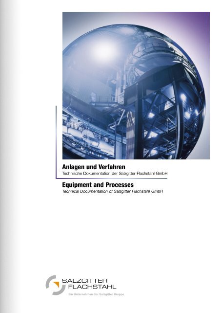
Anlagen und Verfahren<br />
Technische Dokumentation der <strong>Salzgitter</strong> <strong>Flachstahl</strong> <strong>GmbH</strong><br />
Equipment and Processes<br />
Technical Documentation of <strong>Salzgitter</strong> <strong>Flachstahl</strong> <strong>GmbH</strong>
<strong>Salzgitter</strong> Gruppe<br />
<strong>Salzgitter</strong> <strong>Flachstahl</strong> <strong>GmbH</strong><br />
Lageplan<br />
Produktionsanlagen<br />
Kokerei<br />
Sinteranlage<br />
Hochofen<br />
LD-Stahlwerk<br />
Sekundärmetallurgie (VPL-Anlage)<br />
Stranggießanlagen<br />
80’’-Warmbreitbandstraße<br />
Warmbreitbandstraße<br />
Warmbandquerteilanlage<br />
Warmbandspaltanlage<br />
Kaltbreitbandwalzwerk<br />
Kaltbreitbandwalzwerk – Durchlaufbeize<br />
Kaltbreitbandwalzwerk – Schubbeize<br />
Kaltbreitbandwalzwerk – 5-gerüstige Kaltband-Tandemstraße<br />
Kaltbreitbandwalzwerk – Hochkonvektionsglühe<br />
Kaltbreitbandwalzwerk – Dressierstraßen<br />
PRETEX ® -Anlage<br />
Coilinspektionslinien<br />
Spalt- und Verpackungslinie<br />
Oberflächenveredelung – Bandfeuerverzinkungsanlage 1<br />
Oberflächenveredelung – Bandfeuerverzinkungsanlage 2<br />
Oberflächenveredelung – Elektrolytische Verzinkung<br />
Oberflächenveredelung – Bandbeschichtungsanlage 1<br />
Oberflächenveredelung – Bandbeschichtungsanlage 2<br />
4<br />
5<br />
6<br />
8<br />
10<br />
12<br />
14<br />
16<br />
18<br />
20<br />
22<br />
24<br />
26<br />
27<br />
28<br />
30<br />
32<br />
34<br />
36<br />
38<br />
40<br />
42<br />
44<br />
46<br />
48<br />
50<br />
52<br />
54<br />
Inhaltsverzeichnis<br />
Contents<br />
<strong>Salzgitter</strong> Group<br />
<strong>Salzgitter</strong> <strong>Flachstahl</strong> <strong>GmbH</strong><br />
Layout<br />
Production equipment and facilities<br />
Coking plant<br />
Sintering plant<br />
Blast furnace<br />
LD steel plant<br />
Secondary metallurgy (VPL plant)<br />
Continuous casting plant<br />
80’’ Hot strip mill<br />
Hot strip mill<br />
Hot strip cross-cut shearing line<br />
Hot strip slitting line<br />
Cold strip mill<br />
Cold strip mill – Continuous pickling line<br />
Cold strip mill – Push-pull pickling line<br />
Cold strip mill – Five-stand cold rolling tandem mill<br />
Cold strip mill – Hydrogen batch annealing shop<br />
Cold strip mill – Skin pass mill<br />
PRETEX ® -plant<br />
Coil inspection lines<br />
Slitting and Packaging line<br />
Surface coating – Continuous hot-dip galvanizing line 1<br />
Surface coating – Continuous hot-dip galvanizing line 2<br />
Surface coating – Electro-zinc coating line<br />
Surface coating – Coil coating line 1<br />
Surface coating – Coil coating line 2<br />
3
4<br />
<strong>Salzgitter</strong> Gruppe<br />
Die <strong>Salzgitter</strong> Gruppe ist einer<br />
der führenden Stahltechnologie-<br />
Konzerne Europas. Strategischer<br />
Kopf des Konzernes ist die neue<br />
<strong>Salzgitter</strong> AG.<br />
Als Managementholding agiert<br />
sie für die fünf Unternehmensbereiche<br />
Stahl, Handel, Verarbeitung,<br />
Dienstleistung und Röhren.<br />
Sie schafft die Voraussetzung<br />
für weitere Wachstumsschritte<br />
der <strong>Salzgitter</strong> Gruppe.<br />
Den fünf Unternehmensbereichen<br />
sind die selbstständig<br />
operativen Gesellschaften<br />
zugeordnet. Diese handeln mit<br />
hoher Entscheidungsfreiheit<br />
und entwickeln dezentral und<br />
eigenverantwortlich markt-,<br />
produkt- und standortbezogene<br />
Geschäftsaktivitäten. Die klare<br />
Kompetenz- und Aufgabenverteilung<br />
stärkt die Transparenz<br />
und erhöht die Reaktionsfähigkeit.<br />
Dies bildet die Grundlage<br />
für eine positive Identifikation<br />
mit dem Unternehmen und der<br />
Gruppe.<br />
Die umfassende Produktpalette<br />
der <strong>Salzgitter</strong> Gruppe hat ihren<br />
Schwerpunkt in der Entwicklung<br />
und Herstellung von Spezialund<br />
Markenstählen. An den<br />
Produktionsstandorten der<br />
Stahl produzierenden Tochtergesellschaften<br />
wie z. B. der<br />
<strong>Salzgitter</strong> <strong>Flachstahl</strong> <strong>GmbH</strong>, der<br />
Ilsenburger Grobblech <strong>GmbH</strong>,<br />
der Peiner Träger <strong>GmbH</strong> oder<br />
der <strong>Salzgitter</strong> Großrohre <strong>GmbH</strong><br />
lässt sich die Faszination erleben,<br />
die bis heute von der<br />
Stahlherstellung ausgeht. Wie<br />
bei kaum einer anderen Industrie<br />
können Besucher, die<br />
immer herzlich eingeladen sind,<br />
die klassische Stahlherstellung,<br />
aber auch den fließenden Übergang<br />
zur Welt des Hightech<br />
beobachten.<br />
<strong>Salzgitter</strong> is one of the leading<br />
steel technology groups in<br />
Europe, with the newly founded<br />
<strong>Salzgitter</strong> AG as its strategic<br />
nerve centre.<br />
The <strong>Salzgitter</strong> Group is headed<br />
by a management holding<br />
acting as a lead company for<br />
<strong>Salzgitter</strong>’s five divisions: steel,<br />
trading, processing, services<br />
and tubes. This constitutes the<br />
cardinal preconditions for future<br />
Group growth.<br />
Each of these five divisions is<br />
run by an independent<br />
operating company, vested with<br />
extensive decision making<br />
competence. The companies<br />
develop decentralised market,<br />
product and location-related<br />
business activities. The clearly<br />
defined assignment of<br />
responsibilities and tasks<br />
enhances transparency and<br />
capacity for rapid response,<br />
while also establishing a foundation<br />
for strong identification<br />
with the company and the<br />
Group.<br />
The key focus of <strong>Salzgitter</strong>’s<br />
extensive product range is the<br />
development and production<br />
of special and branded steels.<br />
The fascination that the world<br />
of steel has retained to this day<br />
can be experienced first hand<br />
at the steel producing sites of<br />
<strong>Salzgitter</strong>’s subsidiaries such as<br />
<strong>Salzgitter</strong> <strong>Flachstahl</strong> <strong>GmbH</strong>,<br />
Ilsenburger Grobblech <strong>GmbH</strong>,<br />
Peiner Träger <strong>GmbH</strong> or <strong>Salzgitter</strong><br />
Großrohre <strong>GmbH</strong>. As in<br />
few other industries, visitors<br />
are always welcome to observe<br />
traditional steel production as<br />
well as its smooth transition to<br />
the world of high-tech.
Die <strong>Salzgitter</strong> <strong>Flachstahl</strong> <strong>GmbH</strong><br />
– die größte Stahltochter der<br />
<strong>Salzgitter</strong> Gruppe – produziert<br />
am Standort <strong>Salzgitter</strong> hochwertige<br />
Flachprodukte. In einem<br />
modernen, integrierten Hüttenwerk<br />
entstehen Warmband,<br />
Kaltfeinblech und oberflächenveredeltes<br />
Bandmaterial.<br />
Hauptanwendungsgebiete der<br />
<strong>Salzgitter</strong>-Flachprodukte sind<br />
unter anderem der Fahrzeugund<br />
Stahlbau, die Bauindustrie,<br />
der Maschinenbau und die<br />
Haushaltsindustrie.<br />
Das Gütenspektrum umfasst<br />
hochwertige Stahlwerkstoffe mit<br />
engsten Toleranzen hinsichtlich<br />
ihrer mechanischen Kennwerte<br />
und Abmessungen. Das Angebot<br />
reicht von „sehr weichen“<br />
bis „höchstfesten“ Güten.<br />
Gemeinsam mit dem Kunden<br />
werden auf ihre Anwendung<br />
optimierte Stahlprodukte entwickelt.<br />
I-Stahl und das Oberflächentexturierungsverfahren<br />
PRETEX ® sind Beispiele dieser<br />
klaren Kundenorientierung.<br />
Das Potenzial des Werkstoffes<br />
Stahl ist längst nicht erschöpft.<br />
Für seine vollständige Nutzung<br />
muss jedoch die gesamte Prozesskette<br />
von der Produktion<br />
bis zum Recycling betrachtet<br />
werden. In enger, partnerschaftlicher<br />
Kooperation erarbeitet<br />
die <strong>Salzgitter</strong> <strong>Flachstahl</strong> <strong>GmbH</strong><br />
mit Anwendern und Kunden<br />
die erforderlichen zielführenden<br />
Lösungen zur Produkt- und<br />
Prozessoptimierung.<br />
Der Einsatz modernster Anlagen<br />
und die gezielte Investition<br />
in neue Verfahrenstechnologien<br />
sind die Voraussetzung dieser<br />
erfolgreichen Arbeit.<br />
<strong>Salzgitter</strong> <strong>Flachstahl</strong> <strong>GmbH</strong> –<br />
the largest steel subsidiary of<br />
the <strong>Salzgitter</strong> Group – produces<br />
high-quality flat products at the<br />
<strong>Salzgitter</strong> site. A modern, integrated<br />
mill accommodates the<br />
production of hot strip, cold<br />
sheet and surface-finished strip<br />
materials. The main application<br />
areas for <strong>Salzgitter</strong> products<br />
include vehicle manufacturing,<br />
structural steel engineering, the<br />
construction industry, machine<br />
building and the household<br />
goods industry.<br />
The span of steel grades<br />
comprises high-quality materials<br />
with the finest tolerances<br />
with regard to mechanical key<br />
parameters and dimensions.<br />
Grades range from “very soft”<br />
to “high-tensile”. We cooperate<br />
closely with our clients to<br />
develop optimised enhanced<br />
steel products tailored to<br />
specific applications. I-steel<br />
and the PRETEX ® surface<br />
texturing technique are examples<br />
of this consistent customer<br />
orientation.<br />
As a material, steel still holds<br />
considerable potential yet to<br />
be tapped. In order to derive<br />
maximum benefits, however,<br />
the entire process chain – from<br />
production through to recycling<br />
– must be taken into account.<br />
Working in close partnership<br />
with users and clients, <strong>Salzgitter</strong><br />
<strong>Flachstahl</strong> <strong>GmbH</strong> defines the<br />
necessary, objective-driven<br />
solutions for product and<br />
process optimisation.<br />
The utilisation of hyper-modern<br />
facilities and focused investment<br />
in new processing technologies<br />
form the basis of these<br />
successful activities.<br />
<strong>Salzgitter</strong> <strong>Flachstahl</strong> <strong>GmbH</strong><br />
5
6<br />
Lageplan<br />
Layout<br />
Tor 4<br />
1<br />
Tor 3<br />
10 20 30 40 500<br />
2<br />
5<br />
4<br />
3<br />
Tor 2<br />
6<br />
Der Produktionsstandort<br />
<strong>Salzgitter</strong> – seit Jahrzehnten<br />
bürgt der Name für Qualität<br />
und Vielfalt des Werkstoffes<br />
Stahl.<br />
<strong>Salzgitter</strong>´s manufacturing plant<br />
for decades the name has<br />
stood for quality and steel<br />
variety.<br />
8<br />
7<br />
9<br />
10<br />
St
chkanal<br />
Tor 1<br />
1<br />
2<br />
3<br />
4<br />
5<br />
6<br />
7<br />
8<br />
11<br />
Kraftwerk<br />
Hochofen A<br />
Hochofen B<br />
Oxygenstahlwerk<br />
Stranggießanlage<br />
Kokerei<br />
Umweltschutz<br />
Qualitätswesen<br />
12<br />
9<br />
10<br />
11<br />
12<br />
13<br />
14<br />
15<br />
16<br />
13<br />
14<br />
16<br />
Oberflächenveredelungszentrum<br />
Ausbildungszentrum<br />
Kunststoffbeschichtungsanlage<br />
Warmbreitbandwalzwerk<br />
Kaltbreitbandwalzwerk<br />
PRETEX ® -Anlage<br />
Sulfathalle<br />
Hauptverwaltung<br />
1<br />
2<br />
3<br />
4<br />
5<br />
6<br />
7<br />
8<br />
15<br />
Tor 6<br />
Tor 5<br />
Power station<br />
Blast furnace A<br />
Blast furnace B<br />
LD plant<br />
Continuous casting plant<br />
Coking plant<br />
Environmental protection<br />
office<br />
Quality control and<br />
research<br />
9<br />
10<br />
11<br />
12<br />
13<br />
14<br />
15<br />
16<br />
Lageplan<br />
Layout<br />
Surface coating centre<br />
Training centre<br />
Organic coating plant<br />
Hot strip mill<br />
Cold strip mill<br />
PRETEX ® -plant<br />
Sulphat slag store<br />
Headquarters<br />
7
8<br />
Produktionsanlagen<br />
Production equipment and facilities<br />
1<br />
2<br />
3<br />
5<br />
6 7<br />
8<br />
Die Produktionsanlagen der<br />
<strong>Salzgitter</strong> <strong>Flachstahl</strong> <strong>GmbH</strong> im<br />
Stofffluss – von den Koksbatte-<br />
4<br />
15 15 16 16 17<br />
rien über die Hochöfen bis zu<br />
den Weiterverarbeitungs- und<br />
Veredelungswerken.<br />
10<br />
11<br />
12<br />
9<br />
<strong>Salzgitter</strong> <strong>Flachstahl</strong> <strong>GmbH</strong>’s<br />
production facilities showing<br />
the flow of material – from<br />
13<br />
14<br />
coke oven batteries via blast<br />
furnaces to the processing<br />
and coating equipment.
1<br />
2<br />
3<br />
4<br />
5<br />
6<br />
7<br />
8<br />
9<br />
10<br />
11<br />
12<br />
13<br />
14<br />
15<br />
16<br />
17<br />
2 Koksofenbatterien, 108 Koksöfen mit je 46,0 m 3<br />
Sinteranlage – 180 m 2<br />
2 Hochöfen, Gestell-Ø 11,2/10,8 m<br />
3 x 210-t-LD-Konverter<br />
Stranggießanlagen<br />
2 Stränge 250 mm dick, 1.100 - 2.000 mm breit<br />
1 Strang 250 mm dick, 2.000 - 2.600 mm breit<br />
Warmbreitbandwalzwerk<br />
Konti- und Schubbeize<br />
Warmbandzerteilanlage<br />
Kaltwalzwerk<br />
Feuerverzinkung 1 und 2<br />
Elektrolytverzinkung<br />
Bandbeschichtung 1 und 2<br />
Feinblech in Rollen<br />
Feinblech oberflächenveredelt in Rollen<br />
Tafeln<br />
Bandstahl, Felgenband<br />
Warmbreitband<br />
1<br />
2<br />
3<br />
4<br />
5<br />
6<br />
7<br />
8<br />
9<br />
10<br />
11<br />
12<br />
13<br />
14<br />
15<br />
16<br />
17<br />
Produktionsanlagen<br />
Production equipment and facilities<br />
2 Coke oven batteries, 108 coke ovens, 46,0 m 3 each<br />
Sintering plant – 180 m 2<br />
2 Blast furnaces, hearth Ø 11,2/10,8 m<br />
3 x 210 t LD converters<br />
Continuous casting plants:<br />
2 strands 250 mm thick, 1.100 - 2.000 mm wide<br />
1 strand 250 mm thick, 2.000 - 2.600 mm wide<br />
Hot strip mill<br />
Continuous pickling line and push-pull pickling line<br />
Hot strip cutting line<br />
Cold rolling mill<br />
Hot-dip galvanizing No. 1 and 2<br />
Electro-zinc coating line<br />
Organic coating No. 1 and 2<br />
Sheet in coils<br />
Surface-coated sheet in coils<br />
Sheets<br />
Narrow strip, rim material<br />
Hot-rolled strip<br />
9
10<br />
Kokerei<br />
Coking plant<br />
In der werkseigenen Kokerei<br />
wird der für die Erzeugung von<br />
Roheisen notwendige Koks<br />
hergestellt.<br />
Rund 17 Stunden dauert der<br />
Prozess in den 108 Koksöfen,<br />
bei dem der Steinkohle durch<br />
indirekte Beheizung die flüchtigen<br />
Bestandteile entzogen werden.<br />
Das dabei entstehende<br />
Kokereigas wird ebenfalls im<br />
Hüttenwerk eingesetzt.<br />
An own coke oven plant<br />
provides the necessary coke<br />
for pig iron production.<br />
During a process lasting about<br />
17 hours, the volatile components<br />
are withdrawn from the<br />
hard coal by indirect heating in<br />
the 108 coke ovens. The coke<br />
oven gas arising in this process<br />
is also used in the steel<br />
works.
Kokerei – Anlageplan im Querschnitt<br />
Coking plant – Cross-sectional layout<br />
Kapazität 112.000 t/Mon. Gesamtkoks trocken<br />
Öfen 2 x 54<br />
Abmessungen 16,4 x 6,2 x 0,475 m<br />
Füllgewicht 34,5 t<br />
Garzeit 17,3 h<br />
Betriebstemperatur 1.280 - 1.340 °C<br />
Ofenspiele pro Tag 150<br />
Capacity 112.000 t/mo of dry coke<br />
Coke oven chambers 2 x 54<br />
Dimensions 16,4 x 6,2 x 0,475 m<br />
Fill weight 34,5 t<br />
Coking period 17,3 h<br />
Operating temperature 1.280 - 1.340 °C<br />
Daily chamber fillings 150<br />
1<br />
2<br />
3<br />
4<br />
5<br />
6<br />
7<br />
8<br />
9<br />
10<br />
11<br />
12<br />
13<br />
14<br />
15<br />
Kohle von der Misch- und<br />
Mahlanlage<br />
Kohlenbunker<br />
Wiegegefäße<br />
Füllwagen<br />
Ofenkammer<br />
Steigrohr<br />
Regenerator<br />
Überleitmaschine<br />
Löschwagen<br />
Koksrampe<br />
Koks zum Hochofen<br />
Entstaubung Koksausstoß<br />
Druckmaschine<br />
Gas zur Kohlenwertstoffanlage<br />
Kamin<br />
1<br />
2<br />
3<br />
4<br />
5<br />
6<br />
7<br />
8<br />
9<br />
10<br />
11<br />
12<br />
13<br />
14<br />
15<br />
Kokerei<br />
Coking plant<br />
Coal from the mixing and<br />
grinding plant<br />
Coal bunker<br />
Weighing containers<br />
Charging car<br />
Coke oven chamber<br />
Riser<br />
Regenerator<br />
Transfer machine<br />
Quenching car<br />
Coke wharf<br />
Coke for the blast furnace<br />
Dedusting of coke output<br />
Coke pusher<br />
Gas for the coal by<br />
products plant<br />
Chimney<br />
11
12<br />
Sinteranlage<br />
Sintering plant<br />
Aufgabe der Sinteranlage ist<br />
es, feinkörnige Rohstoffe zu<br />
stückfestem Eisenerzsinter für<br />
den Einsatz in den Hochöfen<br />
zu verarbeiten.<br />
Dabei werden zunächst sorgfältig<br />
vorbereitete Gemische<br />
gebildet, die aus Feinerzen,<br />
Konzentraten, Zuschlägen<br />
sowie aus Unterkorn, das bei<br />
Absiebung der stückigen Möllerkomponenten<br />
am Hochofen<br />
anfällt, bestehen. Eisenhaltige,<br />
feinkörnige Abgänge aus der<br />
Produktionskette der gesamten<br />
Hütte werden ebenfalls in die<br />
Gemische eingebracht.<br />
Mit Hilfe eines geeigneten<br />
Brennstoffes wird nach Zündung<br />
im Saugzugverfahren Eisenerzsinter<br />
erzeugt. Brennstoff ist in<br />
der Regel Koksgrus, der aus<br />
der Absiebung von Stückkoks<br />
am Hochofen stammt.<br />
Es werden täglich etwa 6.700 t<br />
Eisenerzsinter erzeugt.<br />
It is the function of the sintering<br />
plant to process fine grain raw<br />
material into coarse grained<br />
iron ore sinter for charging the<br />
blast furnace.<br />
To begin with, meticulously<br />
prepared mixtures are created<br />
consisting of fine ore, concentrates,<br />
extras and undersizes<br />
arising from screening lumpy<br />
burden components at the<br />
blast furnace. Ferriferous fine<br />
grain discharges from the<br />
production chain of the entire<br />
steel works are also put into the<br />
mixtures. By igniting suitable<br />
fuel, iron ore sinter is produced<br />
by down draft process.<br />
Normally, coke breeze from<br />
screening lump coke at the<br />
blast furnace is used as fuel.<br />
The daily production of iron<br />
ore sinter is approximately<br />
6.700 tonnes.
1<br />
2<br />
3<br />
4<br />
5<br />
6<br />
7<br />
8<br />
9<br />
10<br />
11<br />
12<br />
13<br />
14<br />
15<br />
16<br />
Erzhochbahn<br />
Erzentladebunker<br />
Entladestation für Zuschläge<br />
Auftauhalle<br />
Vormischbetten<br />
Reservebetten<br />
Erzmischbetten<br />
Dosierbunker 1-8<br />
Silo 1 und 2<br />
Mischgutbunkeranlage<br />
Entladestation für Koksgrus<br />
Koksgrus-Mahlanlage<br />
Kleinkokslager<br />
Mischtrommel<br />
Sintermaschine<br />
Sinterkühler<br />
Sinterband<br />
Baujahr 1963<br />
Kapazität 2,25 Mio. t/Jahr<br />
Saugfläche 180 m2 Sinterbandbreite 3 m<br />
Unterdruck 100 mbar<br />
Mischtrommel<br />
Baujahr 1999<br />
Zellenkühler<br />
Baujahr 1963<br />
Abgasentstaubung<br />
E-Filter Baujahr 1973/2002<br />
Raumentstaubung<br />
Schlauchfilter Baujahr 2002<br />
17<br />
18<br />
19<br />
20<br />
21<br />
22<br />
23<br />
24<br />
25<br />
26<br />
27<br />
28<br />
29<br />
Sinterverladung z. Hochofen<br />
Umspannstation<br />
E-Filter-Prozessgasentstaubung<br />
Gebläsehalle<br />
Kamine<br />
Betriebswerkstatt<br />
30-kV-Anlage<br />
Raumentstaubung<br />
Kompressoren und<br />
Heizanlagen<br />
Waschkaue<br />
Betriebsgebäude<br />
Koksgasleitung<br />
Öle und Schmierstoffe<br />
Zündhaube<br />
Baujahr 1963<br />
Typ Seitenbrenner<br />
Zündtemperatur 1.200 °C<br />
Großmischbetten<br />
Baujahr 1976<br />
Anzahl 3<br />
Kapazität 3 * 200.000 t<br />
Kleinmischbetten<br />
Baujahr 1940<br />
Anzahl 8<br />
Kapazität 8 * 4.500 t<br />
1<br />
2<br />
3<br />
4<br />
5<br />
6<br />
7<br />
8<br />
9<br />
10<br />
11<br />
12<br />
13<br />
14<br />
15<br />
16<br />
Rail bridges for ore trans<br />
Ore discharging hoppers<br />
Unloading station for extras<br />
Building for train thouring<br />
Preblending yards<br />
Yards for reserve material<br />
Ore blending yards<br />
Dosing hopper 1-8<br />
Silo No. 1 and No. 2<br />
Binds for blending material<br />
Unloading station for coke<br />
breeze<br />
Coke breeze crushing plant<br />
Nut coke storage<br />
Rotary mixing drum<br />
Sintering strand<br />
Sinter cooler<br />
Sintering strand<br />
Year of commissioning 1963<br />
Capacity 2,25 m t/year<br />
Suction area 180 m 2<br />
Width of sintering strand 3 m<br />
Negative pressure 100 mbar<br />
Rotary mixing drum<br />
Year of commissioning 1999<br />
Cooler of cellular type<br />
Year of commissioning 1963<br />
Waste gas dust extraction<br />
Electric precipetator<br />
Year of commissioning ’73/’02<br />
Room dust extraction<br />
Pipe filter<br />
Year of commissioning 2002<br />
Sinteranlage<br />
Sintering plant<br />
Sinteranlage - Anlageplan<br />
Sintering plant - Layout<br />
17<br />
18<br />
19<br />
20<br />
21<br />
22<br />
23<br />
24<br />
25<br />
26<br />
27<br />
28<br />
29<br />
Loading installation for<br />
sinter to be shipped to BF<br />
Transformer station<br />
Electric precipetator process<br />
gas dust extraction<br />
Housing for suction blowers<br />
Stocks<br />
Movintenence workshop<br />
30 kV-Station<br />
Room dust extraction<br />
Compressed air generation,<br />
heating generation<br />
Lavatories<br />
Plant office<br />
Coke gas line<br />
Oil and lubricants<br />
Ignition hood<br />
Year of commissioning 1963<br />
Type Side burners<br />
Ignition temperature 1.200 °C<br />
Ore blending yards<br />
Year of commissioning 1976<br />
Number 3<br />
Capacity 3 * 200.000 t<br />
Preblending yards<br />
Year of commissioning 1940<br />
Number 8<br />
Capacity 8 * 4.500 t<br />
13
14<br />
Hochofen<br />
Blast furnace<br />
Die Hochöfen A und B produzieren<br />
täglich jeweils bis zu<br />
6.000 t Roheisen. Hierfür werden<br />
die Öfen mit Koks, Eisenerz<br />
und Zuschlagsstoffen beschickt.<br />
Unter Zugabe von Schweröl<br />
entsteht bei der Verbrennung<br />
von Koks ein Reduktionsgas,<br />
das dem Eisenoxid den Sauerstoff<br />
entzieht und gleichzeitig<br />
für die erforderliche Schmelztemperatur<br />
sorgt. Der für diesen<br />
Prozess notwendige Sauerstoff<br />
wird in Form von Heißluft zugegeben.<br />
Neben dem Roheisen,<br />
das im Stahlwerk weiterverarbeitet<br />
wird, entstehen Gichtgas<br />
und Schlacke. Auch diese<br />
Nebenprodukte werden aufbereitet<br />
und weiterverwertet.<br />
Daily pig iron output of blast<br />
furnaces A and B amounts to<br />
6.000 tonnes each.<br />
The furnaces are charged with<br />
coke, iron ore and aggregates<br />
for the iron making process.<br />
Adding heavy oil to the burning<br />
coke creates a smelting gas<br />
that draws the oxygen from the<br />
iron oxide and simultaneously<br />
ensures the necessary smelting<br />
temperature. The oxygen<br />
required for this process is<br />
added in the form of hot air.<br />
In addition to the pig iron, which<br />
is processed in the steel making<br />
plant, blast furnace gas and<br />
slag result. These by-products<br />
are also processed and used.
+ 40.800<br />
t<br />
0<br />
t<br />
Ø 8.200<br />
Volumen<br />
2.330 m 3<br />
Ø 12.700<br />
Ø 10.800<br />
Hochofen A B<br />
Gestell-Ø 10,8 m 11,2 m<br />
Nutzvolumen 2.330 m3 2.530 m3 Jahreskapazität 1,8 Mio. t 2,0 Mio. t<br />
Windmenge 260.000 Nm3 /h 270.000 Nm3 /h<br />
Heißwindtemperatur 1.150 °C 1.200 °C<br />
Druck an der Gicht 2,9 bar 3,5 bar<br />
A<br />
+ 40.800<br />
t<br />
0<br />
t<br />
Ø 8.200<br />
Volumen<br />
2.530 m 3<br />
Ø 13.200<br />
Ø 11.200<br />
B<br />
Hochofen<br />
Blast furnace<br />
Blast furnace A B<br />
Hearth Ø 10,8 m 11,2 m<br />
Furnace volume 2.330 m3 2.530 m3 Furnace volume 1,8 million t 2,0 million t<br />
Wind rate 260.000 Nm3 /h 270.000 Nm3 /h<br />
Hot blast temperature<br />
Pressure at<br />
1.150 °C 1.200 °C<br />
furnace top 2,9 bar 3,5 bar<br />
15
16<br />
LD-Stahlwerk<br />
LD steel plant
Stofffluss der Stahlproduktion<br />
Flow of materials for steel production<br />
Im LD-Stahlwerk wird das<br />
Roheisen vom Hochofen unter<br />
Zugabe von Schrott und<br />
Schlackenbildnern zu Rohstahl<br />
verarbeitet. Die im Roheisen<br />
befindlichen Begleitelemente<br />
(C, Si, Mn, P) werden durch<br />
Sauerstoffzufuhr im Konverter<br />
entfernt, sodass nach dem<br />
Sauerstoffblasprozess nahezu<br />
chemisch reines Eisen (Rohstahl)<br />
vorliegt.<br />
The LD steel plant converts<br />
the hot metal from the blast<br />
furnace into crude steel through<br />
the addition of scrap and slag<br />
flux. The tramp elements (C, Si,<br />
Mn, P) in the iron are removed<br />
by oxygen blowing in the converter.<br />
At the end of the process<br />
the result is virtually pure iron<br />
(crude steel).<br />
1<br />
1<br />
2<br />
3<br />
4<br />
5<br />
6<br />
7<br />
8<br />
9<br />
10<br />
1<br />
2<br />
3<br />
4<br />
5<br />
6<br />
7<br />
8<br />
9<br />
10<br />
2 3<br />
4 6 4 5<br />
4<br />
Roheisenantransport<br />
Roheisenmischer<br />
Roheisenentschwefelung<br />
3 x 220-t-LD-Konverter<br />
Zentraler Leitstand<br />
Pfannenöfen/Legierungsstände<br />
VD-Vakuumanlage<br />
Zweistrang-Gießanlage<br />
Einstrang-Gießanlage<br />
Längsteilanlagen<br />
Hot metal transport<br />
Hot metal mixer<br />
Desulphurization stations<br />
3 x 220 t BOF<br />
Main control room<br />
LF, Ladle treatment station<br />
Vacuum-tank-degasser<br />
Twin strand caster<br />
Single strand caster<br />
Slitting lines<br />
8 9<br />
7<br />
10<br />
LD-Stahlwerk<br />
LD steel plant<br />
Konverter A B C<br />
Inbetriebnahme 1969 1976 1968<br />
Modernisierung 1999 – 2000<br />
LD LD LD<br />
Abstichgewicht 220 t 220 t 220 t<br />
Tap-to-tap 45 min 45 min 45 min<br />
Abstichsystem AMEPA/Konverterschieber<br />
Bodenspülung ja ja ja<br />
Entstaubung Elektrotrockenfilter<br />
Converter A B C<br />
Commissioned in 1969 1976 1968<br />
Revamped 1999 – 2000<br />
LDLDLD<br />
Tap weight 220 t 220 t 220 t<br />
Tap-to-tap 45 min 45 min 45 min<br />
Tapping system AMEPA/Sliding gate<br />
Bottom stirring yes yes yes<br />
Dedusting electro dry filter<br />
17
18<br />
Sekundärmetallurgie (VPL-Anlage)<br />
Secondary metallurgy (VPL plant)
VPL-Anlage – Anlageplan<br />
VPL plant – Layout<br />
In der VPL-Anlage wird der im<br />
Konverter erzeugte Rohstahl auf<br />
die vom Kunden geforderte<br />
Analyse fertig behandelt.<br />
Die flexiblen Verarbeitungsschritte<br />
in der VPL-Anlage<br />
(Pfannenofen, Pfannenspülung,<br />
Vakuumbehandlung und Legieren)<br />
gewährleisten ein großes<br />
Spektrum an Stahlgüten.<br />
2<br />
2<br />
2<br />
In the secondary metallurgy<br />
(VPL plant), the crude steel<br />
made in the converter shop is<br />
finished to the required steel<br />
analysis defined by the customer.<br />
The flexible processing<br />
steps in this facility (alloying,<br />
heating, stirring and vacuum<br />
degassing) enable a wide range<br />
of steel grades to be produced.<br />
Sekundärmetallurgie (VPL-Anlage)<br />
Secondary metallurgy (VPL plant)<br />
Pfannenofen<br />
Trafoleistung 25 MVA<br />
Heizrate 3 K/min<br />
Elektroden-Ø 400 mm<br />
Sekundärmetallurgie<br />
1 4 Legierungsstände<br />
2 3 VD-Vakuumgefäße<br />
3 2 Doppel-Pfannenöfen à<br />
24 MVA<br />
3<br />
3<br />
Ladle furnace<br />
Transformer cap. 25 MVA<br />
Heating rate 3 K/min<br />
Electrodes Ø 400 mm<br />
Ladle treatment<br />
1 4 Ladle treatment stations<br />
2 3 Vacuum-tank-degasser<br />
3 2 Twin strand LF à 24 MVA<br />
1<br />
1<br />
1<br />
1<br />
19
20<br />
Stranggießanlagen<br />
Continuous casting plant
Stranggießanlage – Anlageplan im Querschnitt<br />
Continuous casting plant – Cross-sectional layout<br />
Die Stranggießanlagen erzeugen<br />
aus dem fertig konditionierten<br />
Stahl Vorbrammen, die gemäß<br />
Kundenforderungen auf Maß geschnitten<br />
werden. Hierfür stehen<br />
Quer- und Längsteilanlagen zur<br />
Verfügung.<br />
The continuous casters produce<br />
slabs of the finished steel<br />
which are dimensioned to<br />
meet customer requirements.<br />
Cut-to-length and slitting lines<br />
are available for this processing<br />
stage.<br />
Stranggießanlagen<br />
Continuous casting plant<br />
Anlage 1 2<br />
Inbetriebnahme 1981 1973<br />
Modernisierung 1990/91 1987/1991/1996<br />
Anzahl Stränge 1 2<br />
Abmessungen 2.000 - 2.600 x 250 mm 1.100 - 2.000 x 250 mm<br />
Monatskapazität 170.000 t 180.000 t<br />
System DEMAG DEMAG<br />
Bogenanlage Bogenanlage<br />
Radius 10,5 m 10,5 m<br />
4 Biegepunkte 4 Biegepunkte<br />
Länge 34 m 30 m<br />
Pfanneninhalt 220 t 220 t<br />
Verteilerinhalt 26 t 34 t<br />
fliegender Verteilerwechsel<br />
Caster 1 2<br />
Commissioned 1981 1973<br />
Revamped 1990/91 1987/1991/1996<br />
Strands 1 2<br />
Dimensions 2.000 - 2.600 x 250 mm 1.100 - 2.000 x 250 mm<br />
Capacity 170.000 t/mo 180.000 t/mo<br />
System DEMAG DEMAG<br />
bow-type bow-type<br />
Radius 10,5 m 10,5 m<br />
4 bending points 4 bending points<br />
Length 34 m 30 m<br />
Ladle capacity 220 t 220 t<br />
Tundish capacity 26 t 34 t<br />
flying tundish change<br />
21
22<br />
80’’-Warmbreitbandstraße<br />
80’’ Hot strip mill<br />
Beim hier gezeigten Heißeinsatz<br />
werden die noch glühenden<br />
Brammen direkt aus der<br />
Stranggießanlage in die Öfen<br />
eingetragen. Unabhängig von<br />
3 Wärmöfen<br />
Leistung<br />
Brennstoff<br />
2 Stoßöfen<br />
Beheizungsart<br />
Ofenlänge<br />
Lichte Breite<br />
Herdlänge<br />
der Einstoßtemperatur werden<br />
die Brammen in den Öfen auf<br />
eine Temperatur von ca. 1.250 °C<br />
gebracht, bevor sie zu Warmbreitband<br />
ausgewalzt werden.<br />
240 t/h<br />
Erdgas und Koksgas<br />
1 Hubbalkenofen (Baujahr 2001)<br />
Beheizungsart<br />
144 Deckenbrenner,<br />
18 Seitenbrenner,<br />
22 Unterzonenbrenner<br />
Ofenlänge<br />
33,8 m<br />
Lichte Breite<br />
13,6 m<br />
166 Deckenbrenner,<br />
8 Unterzonenbrenner<br />
31,0 m<br />
13,2 m<br />
16,0 m<br />
In the hot charging process<br />
shown here, the red hot slabs<br />
are transferred directly from the<br />
continuous casting plants into<br />
the furnaces. Irrespective of<br />
3 Reheating furnaces<br />
Capacity<br />
Fuel<br />
2 Pusher-type furnaces<br />
Type of heating<br />
Furnace length<br />
Clear span<br />
Hearth length<br />
their temperature on entry, the<br />
slabs are heated to 1.250 °C<br />
before being hot rolled into<br />
wide strip.<br />
240 t/h<br />
natural and coke oven gas<br />
1 Walking beam furnace (Year of commissioning 2001)<br />
Type of heating<br />
144 roof burners,<br />
18 side burners,<br />
22 subzone burners<br />
Furnace length<br />
33,8 m<br />
Clear span<br />
13,6 m<br />
166 roof burners,<br />
8 subzone burners<br />
31,0 m<br />
13,2 m<br />
16,0 m
Stauchpresse<br />
Antriebsleistung<br />
Stauchkraft<br />
Stauchmaß<br />
Stauchgerüst<br />
Stauchwalzen-Ø<br />
Antriebsleistung<br />
Walzmoment<br />
Walzkraft<br />
Horizontalgerüst<br />
Stützwalzen-Ø<br />
Arbeitswalzen-Ø<br />
Antriebsleistung<br />
Walzmoment<br />
Walzkraft<br />
Fertigstraße (7 Gerüste)<br />
Stützwalzen-Ø<br />
Arbeitswalzen-Ø<br />
Antriebsleistung<br />
Geschwindigkeit<br />
Anstellung<br />
2 Unterflurhaspel<br />
Bundaußen-Ø<br />
Dorn-Ø<br />
Bundgewicht<br />
Antriebsleistung<br />
Anzahl Andrückrollen<br />
Anstellungen<br />
Coilbindelinie<br />
Walzprogramm<br />
Dicken<br />
Breiten<br />
Güten<br />
4,4 MW<br />
22.000 kN<br />
max. 350 mm<br />
Vorstraße (Quarto mit Staucher) Roughing train (four-high with edger)<br />
1.100 mm - 1.000 mm<br />
min. 2 x 1,5 MW/max. 2 x 3,75 MW<br />
max. 2 x 593 kNm<br />
6.000 kN<br />
1.650 mm - 1.450 mm<br />
1.250 mm - 1.125 mm<br />
min. 2 x 8,5 MW/max. 2 x 20 MW<br />
max. 2 x 3.820 kNm<br />
55.000 kN<br />
1.525 mm - 1.375 mm<br />
760 mm - 670 mm<br />
7 x 2 x 3.300 kW<br />
max. 20 m/s<br />
Hydraulik<br />
max. 2.100 mm<br />
760 mm<br />
max. 32 t<br />
1.200 kW<br />
3<br />
Hydraulik<br />
Autom. Adjustieren von Coils<br />
1,5 - 25,0 mm<br />
900 - 1.880 mm<br />
Feinblech- und Festigkeitsgüten<br />
Kohlenstoffstähle bis C75<br />
Röhrenstähle bis X75<br />
Sizing press<br />
Driving Power<br />
Sizing force<br />
Sizing width<br />
Edging stand<br />
Edger rolls Ø<br />
Driving Power<br />
Rolling torque<br />
Rolling force<br />
Horizontal stand<br />
Backup roll Ø<br />
Work roll Ø<br />
Driving Power<br />
Rolling torque<br />
Rolling force<br />
Finishing train (7 stands)<br />
Backup roll Ø<br />
Work roll Ø<br />
Driving Power<br />
Speed<br />
Roll gap setting system<br />
2 Downcoilers<br />
Outer coil Ø<br />
Mandrel Ø<br />
Coil weigth<br />
Driving Power<br />
Number of wrapper rolls<br />
Setting systems<br />
Coil binding line<br />
Product range<br />
Thicknesses<br />
Widths<br />
Steel grades<br />
80’’-Warmbreitbandstraße<br />
80’’ Hot strip mill<br />
4,4 MW<br />
22.000 kN<br />
max. 350 mm<br />
1.100 mm - 1.000 mm<br />
min. 2 x 1,5 MW/max. 2 x 3,75 MW<br />
max. 2 x 593 kNm<br />
6.000 kN<br />
1.650 mm - 1.450 mm<br />
1.250 mm - 1.125 mm<br />
min. 2 x 8,5 MW/max. 2 x 20 MW<br />
max. 2 x 3.820 kNm<br />
55.000 kN<br />
1.525 mm - 1.375 mm<br />
760 mm - 670 mm<br />
7 x 2 x 3.300 kW<br />
max. 20 m/s<br />
hydraulic<br />
max. 2.100 mm<br />
760 mm<br />
max. 32 t<br />
1.200 kW<br />
3<br />
hydraulic<br />
automatic coil binding<br />
1,5 - 25,0 mm<br />
900 - 1.880 mm<br />
Normal low carbon grades –<br />
High-strength grades<br />
Carbon steels up to C75<br />
Pipe steels up to X75<br />
23
24<br />
Warmbreitbandstraße<br />
Hot strip mill<br />
In der Fertigstraße werden Vorbänder<br />
zu Warmbreitband ausgewalzt.<br />
Das fertige Material<br />
verlässt die Anlage (siehe Zeichnung)<br />
mit einer Geschwindigkeit<br />
von max. 20 m/s.<br />
In the finishing train, transfer<br />
bars are rolled out to form hot<br />
rolled wide strips. The finished<br />
material leaves the train (see<br />
diagram) at a maximum speed<br />
of 20 m/s.
1<br />
2<br />
3<br />
4<br />
5<br />
6<br />
7<br />
8<br />
9<br />
10<br />
11<br />
12<br />
6<br />
1<br />
Vorbrammenzufuhrrollgang<br />
Entbartungsanlage<br />
Wärmofen Nr. 5, Hubbalkenofen<br />
Wärmofen Nr. 4, Stoßofen<br />
Wärmofen Nr. 3, Stoßofen<br />
Abgaswärmenutzung der<br />
Öfen 3, 4, 5<br />
Presswasserentzunderung<br />
Brammenstauchpresse<br />
Vorstraße<br />
Schopfschere<br />
Presswasserentzunderung<br />
Fertigstaffel<br />
2<br />
3<br />
7<br />
4<br />
13<br />
14<br />
15<br />
16<br />
17<br />
18<br />
19<br />
20<br />
21<br />
22<br />
23<br />
8<br />
5<br />
9<br />
Auslaufrollgang/<br />
Bandkühlung<br />
Unterflurhaspel<br />
Coilquertransport<br />
Coillängstransport<br />
Rohbundwaage<br />
Muldenhubbalken<br />
Höckerhubbalken<br />
Schopf- und<br />
Probenschere<br />
Coilaußenumreifung<br />
Umreifung durch das<br />
Coilauge<br />
Fertigbundwaage<br />
10 11<br />
1<br />
2<br />
3<br />
4<br />
5<br />
6<br />
7<br />
8<br />
9<br />
10<br />
11<br />
18<br />
17<br />
19<br />
16<br />
12<br />
13<br />
14<br />
14<br />
Slab roller table<br />
Deburring device<br />
Reheating furnace No. 5,<br />
walking beam furnace<br />
Reheating furnace No. 4,<br />
pusher-type furnace<br />
Reheating furnace No. 3,<br />
pusher-type furnace<br />
Waste gas heat recovery<br />
furnaces 3, 4, 5<br />
High-pressure water<br />
descaling<br />
Sizing press<br />
Roughing train<br />
Crop shear<br />
High-pressure water<br />
descaling<br />
Warmbreitbandstraße<br />
20 212223<br />
12<br />
13<br />
14<br />
15<br />
16<br />
17<br />
18<br />
19<br />
20<br />
21<br />
22<br />
23<br />
15<br />
Hot strip mill<br />
Warmbreitbandstraße – Anlageplan<br />
Hot strip mill – Layout<br />
Finishing train<br />
Runout table/strip cooling<br />
Downcoilers<br />
Transverse transport of coils<br />
Longitudinal transport of<br />
coils<br />
Coil weighting machine<br />
Walking beam conveyer<br />
V-plate conveyer<br />
Shear for cropping and<br />
sampling<br />
Outer coil binding<br />
Binding through the coil eye<br />
Finished coil weighting<br />
machine<br />
25
26<br />
Warmbandquerteilanlage<br />
Hot strip cross-cut shearing line<br />
11<br />
Warmbandquerteilanlage – Anlageplan<br />
Hot strip cross-cut shearing line – Layout<br />
Bandbreitenbereich 900 - 1.880 mm<br />
Banddickenbereich 1,5 - 6,0 mm<br />
Einsatzgewicht max. 32 t<br />
Tafellänge min. 1.000 mm<br />
max. 12.000 mm<br />
Anlagengeschwindigkeit 60 m/min<br />
Strip width range 900 - 1.880 mm<br />
Strip thickness range 1,5 - 6,0 mm<br />
Coil weight max. 32 t<br />
Sheet length min. 1.000 mm<br />
max. 12.000 mm<br />
Line speed 60 m/min<br />
10<br />
9<br />
1<br />
2<br />
3<br />
4<br />
5<br />
6<br />
7<br />
8<br />
9<br />
10<br />
11<br />
8<br />
7<br />
Coilzuführung<br />
Abhaspel<br />
Einlauftreiber<br />
Stempelmaschine<br />
Besäumschere<br />
Saumschrottzerhacker<br />
Richtmaschine 1<br />
Querteilschere<br />
Richtmaschine 2<br />
Stapelvorrichtung 1<br />
Stapelvorrichtung 2<br />
6<br />
5<br />
1<br />
2<br />
3<br />
4<br />
5<br />
6<br />
7<br />
8<br />
9<br />
10<br />
11<br />
4<br />
3<br />
Coil entry transfer<br />
Uncoiler<br />
Entry pinch roll<br />
Marking machine<br />
Trimming shear<br />
Trimming scrap chopper<br />
Leveller 1<br />
Cross-cut shear<br />
Leveller 2<br />
Stacker 1<br />
Stacker 2<br />
2<br />
1
Bandbreitenbereich 700 - 1.650 mm<br />
Banddickenbereich 1,5 - 10,0 mm<br />
Teilstreifenbreitenbereich 100 - 1.600 mm<br />
Bundgewicht, Ein- und Auslauf 32 t<br />
Bundaußen-Ø, Einlauf 1.200 - 2.100 mm<br />
Bundinnen-Ø, Einlauf 610 mm und 760 mm<br />
Bundaußen-Ø, Auslauf 1.000 - 2.100 mm<br />
Bundinnen-Ø, Auslauf 508 mm und 610 mm<br />
Ein- u. Ausfädelgeschwindigkeit 0 - 25 m/min<br />
Spalt- u. Besäumgeschwindigkeit max. 240 m/min<br />
Strip width range 700 - 1.650 mm<br />
Strip thickness range 1,5 - 10,0 mm<br />
Slit strip width range 100 - 1.600 mm<br />
Coil weight, entry/delivery section 32 t<br />
Outer entry coil Ø 1.200 - 2.100 mm<br />
Inner entry coil Ø 610 mm and 760 mm<br />
Outer exit coil Ø 1.000 - 2.100 mm<br />
Inner exit coil Ø 508 mm and 610 mm<br />
Threading in and out speed 0 - 25 m/min<br />
Slitting and trimming speed max. 240 m/min<br />
1<br />
2<br />
3<br />
4<br />
5<br />
6<br />
7<br />
8<br />
9<br />
10<br />
11<br />
12<br />
13<br />
14<br />
15<br />
16<br />
17<br />
18<br />
19<br />
Abhaspel<br />
Richtmaschine<br />
Inspektionsstand 1<br />
Querteilschere<br />
Streifenschere<br />
Saumschrottzerhacker<br />
Schlingengrube<br />
Bremsgerüst<br />
Querteilschere<br />
Aufhaspel<br />
Bundhubwagen<br />
Umreifung (Außen)<br />
Kippstuhl<br />
Umreifung durch das<br />
Coilauge<br />
Ablagegestell/Stapler<br />
Drehteller<br />
Paket-Umreifung<br />
Bund-Übernahmewagen<br />
Kippstuhl<br />
Warmbandspaltanlage<br />
Hot strip slitting line<br />
Warmbandspaltanlage – Anlageplan<br />
Hot strip slitting line – Layout<br />
1<br />
2<br />
3<br />
4<br />
5<br />
6<br />
7<br />
8<br />
9<br />
10<br />
11<br />
12<br />
13<br />
14<br />
15<br />
16<br />
17<br />
18<br />
19<br />
Uncoiler<br />
Leveller<br />
Inspection station 1<br />
Cross-cut shear<br />
Slitting shear<br />
Trimming scrap chopper<br />
Looping pit<br />
Braking unit<br />
Cross-cut shear<br />
Reel<br />
Coil car<br />
Coil banding (outer)<br />
Downer<br />
Coil banding (inner)<br />
Delivery frame/stacker<br />
Rotary feed table<br />
Pack banding<br />
Coil transfer car<br />
Up-ender<br />
27
28<br />
Kaltbreitbandwalzwerk<br />
Cold strip mill<br />
Im Kaltbreitbandwalzwerk wird<br />
das Warmbreitband auf die vom<br />
Kunden gewünschten Maße<br />
heruntergewalzt.<br />
The hot strip is rolled down to<br />
the thickness required by the<br />
customer on the cold strip mill.
3<br />
Kaltbreitbandwalzwerk – Anlageplan<br />
Cold strip mill – Layout<br />
1<br />
2<br />
3<br />
4<br />
Schubbeize<br />
Konti-Beize<br />
Tandemstraße<br />
Glüherei<br />
5<br />
5<br />
6<br />
7<br />
Dressierstraßen 1, 2 und 3<br />
Streckrichtanlage<br />
Coilinspektionslinien<br />
4<br />
5<br />
1<br />
2<br />
3<br />
4<br />
6<br />
Push-pull pickling line<br />
Continuous pickling line<br />
Tandem mill<br />
Annealing shop<br />
Kaltbreitbandwalzwerk<br />
7<br />
5<br />
5<br />
6<br />
7<br />
1<br />
7<br />
Cold strip mill<br />
Skin pass mills 1, 2 and 3<br />
Tension leveller<br />
Coil inspection lines<br />
7<br />
2<br />
29
30<br />
Kaltbreitbandwalzwerk – Durchlaufbeize<br />
Cold strip mill – Continuous pickling line<br />
Bandbreitenbereich 900 - 1.900 mm<br />
Banddickenbereich 1,5 - 6,5 mm<br />
Coilgewicht max. 32 t<br />
Innen-Ø, Einlauf 760 mm<br />
Innen-Ø, Auslauf 610 mm<br />
Einlaufgeschwindigkeit 610 m/min<br />
Beizgeschwindigkeit 260 m/min<br />
Auslaufgeschwindigkeit 350 m/min<br />
Beizmedium Schwefelsäure<br />
Beizbadlänge 135 m<br />
Kapazität 150.000 t/Mon.<br />
Strip width range 900 - 1.900 mm<br />
Strip thickness range 1,5 - 6,5 mm<br />
Coil weight max. 32 t<br />
Inner Ø at entry 760 mm<br />
Inner Ø at exit 610 mm<br />
Entry speed 610 m/min<br />
Pickling speed 260 m/min<br />
Exit speed 350 m/min<br />
Pickling agent sulphuric acid<br />
Pickling bath length 135 m<br />
Capacity 150.000 t/mo
In der Beizlinie wird das Warmbreitband<br />
vom Oberflächenzunder<br />
befreit.<br />
Superficial scale is removed<br />
from the hot strip in the pickling<br />
line.<br />
1<br />
2<br />
3<br />
4<br />
5<br />
6<br />
7<br />
8<br />
9<br />
10<br />
11<br />
12<br />
13<br />
14<br />
15<br />
16<br />
17<br />
Kaltbreitbandwalzwerk – Durchlaufbeize<br />
Cold strip mill – Continuous pickling line<br />
Hubbalkenförderer<br />
Bundvorbereitungshaspel<br />
Bundvorbereitung<br />
Hilfshaspel<br />
Abwickelhaspel<br />
Treibapparat und Richtmaschine<br />
Schweißmaschine<br />
Schlingenspeicher<br />
Streckbiegerichter<br />
Flachbeize<br />
Spülbereich<br />
Trockner<br />
Auslaufschlingenspeicher<br />
Inspektionsstand<br />
Besäumscheren<br />
Einölmaschine<br />
Aufwickelhaspel<br />
Durchlaufbeize – Anlageplan<br />
Continuous pickling line – Layout<br />
1<br />
2<br />
3<br />
4<br />
5<br />
6<br />
7<br />
8<br />
9<br />
10<br />
11<br />
12<br />
13<br />
14<br />
15<br />
16<br />
17<br />
Walking beam conveyor<br />
Coil preparation pay-off<br />
reel<br />
Coil preparation<br />
Auxiliary pay-off reel<br />
Pay-off reel<br />
Pinch roll and leveller<br />
Welding machine<br />
Entry loop accumulator<br />
Tension leveller<br />
Shallow pickling bath<br />
Rinsing-section<br />
Dryer<br />
Exit loop accumulator<br />
Inspection station<br />
Trimming shears<br />
Electrostatic oiler<br />
Tension reel<br />
31
32<br />
Kaltbreitbandwalzwerk – Schubbeize<br />
Cold strip mill – Push-pull pickling line
Schubbeize – Anlageplan<br />
Push-pull pickling line – Layout<br />
Bandbreitenbereich 650 - 1.500 mm<br />
Banddickenbereich 1,5 - 12,5 mm<br />
Coilgewicht max. 32 t<br />
Innen Ø, Einlauf 760 mm<br />
Innen Ø, Auslauf 610 mm<br />
Beizgeschwindigkeit 90 m/min<br />
Beizmedium Salzsäure<br />
Kapazität 45.000 t/Mon.<br />
Strip width range 650 - 1.500 mm<br />
Strip thickness range 1,5 - 12,5 mm<br />
Coil weight max. 32 t<br />
Inner Ø at entry 760 mm<br />
Inner Ø at exit 610 mm<br />
Pickling speed 90 m/min<br />
Pickling agent hydrochlorid acid<br />
Capacity 45.000 t/mo<br />
1<br />
2<br />
3<br />
4<br />
5<br />
6<br />
7<br />
8<br />
9<br />
10<br />
11<br />
12<br />
13<br />
Kaltbreitbandwalzwerk – Schubbeize<br />
Cold strip mill – Push-pull pickling line<br />
Bundvorbereitung<br />
Abwickelhaspel<br />
Richtmaschine<br />
Beizbecken<br />
Spülzone<br />
Bandtrockner<br />
Inspektionsstand<br />
Besäumschere<br />
Umlaufgerüst<br />
Dressiergerüst<br />
Inspektionsstand<br />
Einölmaschine<br />
Aufwickelhaspel<br />
Bei besonderen Qualitäten<br />
(z. B. Stahl 52), die nicht miteinander<br />
verschweißt werden<br />
können, erfolgt die Beizung der<br />
Coils einzeln in der Schubbeize.<br />
Where particular grades<br />
(e. g. steel 52) cannot be<br />
welded to each other, the<br />
coils are pickled individually<br />
in a push-pull pickling line.<br />
1<br />
2<br />
3<br />
4<br />
5<br />
6<br />
7<br />
8<br />
9<br />
10<br />
11<br />
12<br />
13<br />
Coil preparation<br />
Pay-off reel<br />
Levelling machine<br />
Pickling tank<br />
Rinsing section<br />
Drying section<br />
Inspection station<br />
Edge trimmer<br />
Back tension stand<br />
Skin pass mill stand<br />
Inspection station<br />
Electrostatic oiler<br />
Tension reel<br />
33
34<br />
Kaltbreitbandwalzwerk – 5-gerüstige Kaltband-Tandemstraße<br />
Cold strip mill – Five-stand cold rolling tandem mill<br />
Im Auslauf der Tandemstraße sind die Coils auf ihre Enddicke<br />
gewalzt worden.<br />
Gerüst 1 2 3 4 5<br />
Bauart Quarto Quarto Quarto Quarto Sexto<br />
Anstellung hydraulisch hydraulisch hydraulisch hydraulisch hydraulisch<br />
Arbeitswalzen-Ø 560 mm 560 mm 560 mm 560 mm 475 mm<br />
Zwischenwalzen - - - - 575 mm<br />
Stützwalzen-Ø 1.420 mm 1.420 mm 1.420 mm 1.420 mm 1.420 mm<br />
Walzenballenlänge 2.030 mm 2.030 mm 2.030 mm 2.030 mm 2.030 mm<br />
Walzkraft/Gerüst 2.700 t 2.700 t 2.700 t 2.700 t 2.700 t<br />
Antrieb 2 x 2 x 1.500 kW 2 x 2 x 1.650 kW 2 x 2 x 1.650 kW 2 x 2 x 1.650 kW 2 x 2.700 kW<br />
Drehzahl 149/568 U/min 202/568 U/min 246/568 U/min 202/568 U/min 400/868 U/min<br />
Bandzüge vor Gerüst max. 9 t max. 55 t max. 55 t max. 55 t max. 18 t<br />
Walzgeschwindigkeit max. 770 m/min max. 930 m/min max. 1.080 m/min max. 1.260 m/min max. 1.425 m/min<br />
Bandbreitenbereich 900 - 1.880 mm<br />
Banddickenbereich 0,3 - 3,5 mm<br />
Bundgewicht max. 32 t<br />
Bandzug max. 55 t<br />
Kapazität 125.000 t/Mon.<br />
The coil is rolled down to its final thickness at the end of the<br />
tandem mill.
Qualifizierte Mitarbeiter und moderne Steuertechnik gewährleisten<br />
den reibungslosen Produktionsablauf und die konstant hohe<br />
Qualität.<br />
Kaltbreitbandwalzwerk – 5-gerüstige Kaltband-Tandemstraße<br />
Cold strip mill – Five-stand cold rolling tandem mill<br />
Stand no. 1 2 3 4 5<br />
Type four-high four-high four-high four-high six-high<br />
Adjustment hydraulic hydraulic hydraulic hydraulic hydraulic<br />
Work roll Ø 560 mm 560 mm 560 mm 560 mm 475 mm<br />
Intermediate roll Ø - - - - 575 mm<br />
Backup roll Ø 1.420 mm 1.420 mm 1.420 mm 1.420 mm 1.420 mm<br />
Roll barrel length 2.030 mm 2.030 mm 2.030 mm 2.030 mm 2.030 mm<br />
Rolling force/stand 2.700 t 2.700 t 2.700 t 2.700 t 2.700 t<br />
Drive power 2 x 2 x 1.500 kW 2 x 2 x 1.650 kW 2 x 2 x 1.650 kW 2 x 2 x 1.650 kW 2 x 2.700 kW<br />
Speed 149/568 U/min 202/568 U/min 246/568 U/min 202/568 U/min 400/868 U/min<br />
Strip tension max. 9 t max. 55 t max. 55 t max. 55 t max. 18 t<br />
Rolling speed max. 770 m/min max. 930 m/min max. 1.080 m/min max. 1.260 m/min max. 1.425 m/min<br />
Strip width range 900 - 1.880 mm<br />
Strip thickness range 0,3 - 3,5 mm<br />
Coil weight max. 32 t<br />
Strip tension max. 55 t<br />
Capacity 125.000 t/mo<br />
Qualified employees and modern control panels guarantee a<br />
smooth flow of production and a consistently high quality.<br />
35
36<br />
Kaltbreitbandwalzwerk – Hochkonvektionsglühe<br />
Cold strip mill – Hydrogen batch annealing shop<br />
In der Glüherei wird das durch die Kaltverformung verfestigte<br />
Material bei Temperaturen von bis zu 700 °C geglüht.<br />
Chargengewicht<br />
Packhöhe<br />
Schutzgas<br />
Schutzgasumwälzmenge<br />
Glühleistung<br />
Kühlleistung<br />
Oberflächensauberkeit<br />
Anzahl Glühhauben<br />
Anzahl Glühsockel<br />
Kapazität<br />
115 t<br />
5.000 mm<br />
H 2<br />
50.000 m 3 /h<br />
Ø 2,7 t/h<br />
Ø 3,4 t/h<br />
< 5 mg C/m 2<br />
47<br />
81<br />
72.000 t/Mon.<br />
The material which has hardened during cold-forming is annealed<br />
at temperatures of up to 700 °C in the annealing plant.<br />
Batch weight<br />
Stack height<br />
Protective gas<br />
Volume of circulated<br />
protective gas<br />
Annealing capacity<br />
Cooling capacity<br />
Surface cleanness<br />
Number of annealing batches<br />
Number of bases<br />
Capacity<br />
115 t<br />
5.000 mm<br />
H 2<br />
50.000 m 3 /h<br />
Ø 2,7 t/h<br />
Ø 3,4 t/h<br />
< 5 mg C/m 2<br />
47<br />
81<br />
72.000 t/mo
Kaltbreitbandwalzwerk – Hochkonvektionsglühe<br />
Cold strip mill – Hydrogen batch annealing shop<br />
37
38<br />
Kaltbreitbandwalzwerk – Dressierstraßen<br />
Cold strip mill – Skin pass mill<br />
Durch die abschließende Kaltverformung<br />
erhält das Feinblech<br />
in der Dressierstraße definierte<br />
mechanisch-technologische und<br />
geometrische Eigenschaften<br />
(Streckgrenze, Rauheit, Planheit).<br />
The sheet is given well defined<br />
mechanical, technological and<br />
geometrical properties (yield<br />
stress, roughness, flatness) by<br />
the final cold forming process<br />
in the skin pass mill.<br />
Dressierstraße 1 2 3<br />
Gerüsttyp Quarto Quarto Quarto (2 Gerüste)<br />
Bandbreitenbereich 900 - 1.880 mm 900 - 1.500 mm 800 - 1.880 mm<br />
Banddickenbereich 0,5 - 4,0 mm 0,3 - 3,0 mm 0,3 - 3,5 mm<br />
Bundgewicht max. 32 t max. 32 t max. 32 t<br />
Streckung max. 3 % max. 10 % max. 2,5 %<br />
Geschwindigkeit max. 1.200 m/min max. 1.500 m/min max. 1.000 m/min<br />
Walzkraft max. 1.600 t max. 1.800 t max. 1.600 t<br />
Walzenanstellung hydraulisch hydraulisch hydraulisch<br />
Streckgradregelung automatisch automatisch automatisch<br />
Kombination mit Streckrichtmaschine - -<br />
Kapazität 60.000 t/Mon. 60.000 t/Mon. 90.000 t/Mon.<br />
Skin pass mill 1 2 3<br />
Type of stand four-high four-high four-high (2 stands)<br />
Strip width range 900 - 1.880 mm 900 - 1.500 mm 800 - 1.880 mm<br />
Strip thickness range 0,5 - 4,0 mm 0,3 - 3,0 mm 0,3 - 3,5 mm<br />
Coil weight max. 32t max. 32t max. 32t<br />
Elongation max. 3 % max. 10 % max. 2,5 %<br />
Speed max. 1.200 m/min max. 1.500 m/min max. 1.000 m/min<br />
Rolling force max. 1.600 t max. 1.800 t max. 1.600 t<br />
Roll adjustment hydraulic hydraulic hydraulic<br />
Tension leveller control automatic automatic automatic<br />
Combination with tension leveller - -<br />
Capacity 60.000 t/mo 60.000 t/mo 90.000 t/mo
Dressierstraße 3<br />
Gerüsttyp Quarto<br />
Anzahl der Gerüste 2<br />
Kapazität 90.000 t/Mon.<br />
Bandbreitenbereich 800 - 1.880 mm<br />
Banddickenbereich 0,3 - 3,5 mm<br />
Bund-Ø max. 2.100 mm<br />
Bundgewicht max. 32 t<br />
Anlagengeschwindigkeit 15 - 1.000 m/min.<br />
Walzkraft max. 16 mN pro Gerüst<br />
Biegekraft max. +/-1.600 kN<br />
Dressiergrad 0,2 - 2,5 %<br />
Antriebsleistung des Abhaspels 2 x 1.000 kW<br />
Antriebsleistung des Einlauf-Treibers 2 x 1.000 kW<br />
Antriebsleistung von Gerüst Nr. 1 2 x 1.000 kW<br />
Antriebsleistung von Gerüst Nr. 2 2 x 1.000 kW<br />
Antriebsleistung des Aufhaspels 2 x 1.000 kW<br />
Bandzug: Abhaspel – Einlauf-Treiber 5 - 80 kN<br />
Kaltbreitbandwalzwerk – Dressierstraßen<br />
Cold strip mill – Skin pass mill<br />
Dressierstraße 3 – Anlageplan<br />
Skin pass mill 3 – Layout<br />
Skin pass mill<br />
Type of stand quarto<br />
Stands 2<br />
Capacity 90.000 t/mo<br />
Strip width range 800 - 1.880 mm<br />
Strip thickness range 0,3 - 3,5 mm<br />
Coil Ø max. 2.100 mm<br />
Coil weight max. 32t<br />
Unit speed 15 - 1.000 m/min.<br />
Rolling force max. 16 mN per frame<br />
Bending force max. +/-1.600 kN<br />
Elongation range 0,2 - 2,5 %<br />
Driving power of uncoiler 2 x 1.000 kW<br />
Driving power of loading bridle 2 x 1.000 kW<br />
Driving power of frame No. 1 2 x 1.000 kW<br />
Driving power of frame No. 22 x 1.000 kW<br />
Driving power of coiler<br />
Front tension: uncoiler – loading<br />
2 x 1.000 kW<br />
bridle 5 - 80 kN<br />
39
40<br />
PRETEX ® -Anlage<br />
PRETEX ® -plant<br />
Die Oberflächenfeingestalt des Feinbleches ist ein wesentliches<br />
qualitätsrelevantes Produktmerkmal. Im Gegensatz zu herkömmlichen<br />
Texturierungsverfahren ermöglicht das neue PRETEX ® -<br />
Verfahren auch zukünftig die sichere Erfüllung höchster Anforderungen<br />
an ein hervorragendes tribologisches Umformverhalten und<br />
brillante optische Lackeigenschaften. Hierfür werden die Arbeitswalzen<br />
in einem geschlossenen Reaktorsystem mit TOPOCROM ®<br />
beschichtet. Beim Nachwalzen im Dressiergerüst wird dann durch<br />
Abprägen der TOPOCROM ® -Struktur auf das Feinblech eine<br />
definierte PRETEX ® -Feinblechstruktur erzeugt.<br />
The microscopic examination of the surface of steel sheets is a<br />
major quality feature of the product. Unlike standard texturing<br />
methods, the new PRETEX ® process also ensures reliable<br />
fulfilment of the highest demands for outstanding tribological<br />
reforming behaviour and brilliant optical painting characteristics<br />
for the future. The work rolls are coated with TOPOCROM ® in a<br />
closed-circuit reactor system for this purpose. The defined<br />
PRETEX ® surface texture is created by impressing the<br />
TOPOCROM ® structure on the steel sheet during skin passing.
PRETEX ® -Reaktor<br />
PRETEX ®-Reactor<br />
– Pol / Pole<br />
+ Pol / Pole<br />
Reaktor<br />
Reactor<br />
Zapfen-<br />
Schutzhülse<br />
Shaft<br />
protection<br />
sleeve<br />
+ Anode – Kathode<br />
– Cathode<br />
+ Anode<br />
Walze<br />
Roll<br />
Chrom-Elektrolyt<br />
Chrome electrolyte<br />
Die stochastische Rauheitsstruktur zeichnet sich durch zahlreiche<br />
fein verteilte hydrostatische Schmiertaschen und – selbst bei<br />
hohen Mittenrauwerten – extrem hohe Spitzenzahlen aus. Die<br />
Rauheitskennwerte sind absolut gleichmäßig über die Bandbreite<br />
und -länge verteilt. Unter Vermeidung von Tränenbildung werden<br />
eine gute Lackhaftung und geringe längerwellige, den Orangenhauteffekt<br />
verursachende Strukturanteile sichergestellt. Gleichzeitig<br />
werden störende Moiré-Effekte sicher vermieden. Sämtliche<br />
Qualitätsforderungen an ein hervorragendes tribologisches Umformverhalten<br />
und brillante optische Lackeigenschaften werden<br />
gleichermaßen gut erfüllt.<br />
PRETEX ® -Anlage<br />
zur Struktur-Hartverchromung von Arbeitswalzen<br />
Inbetriebnahme 1996<br />
Ausbau/Modernisierung 1998<br />
Anzahl Reaktoren 2<br />
Gleichrichter 2 (0 - 18 V/40 kA)<br />
Steuerungen 2 (Siemens SPS/OP 37)<br />
Walzenlängen 3.500 - 4.700 mm<br />
Ballen-Ø 400 - 650 mm<br />
Schichtdicken (Strukturchrom) 60 - 120 µm<br />
Mittenrauwerte Ra (SEP 1940) 0,4 - 20 µm<br />
Spitzenzahlen Pc (SEP 1940) 60 - 180 cm -1<br />
Schichtdicken (Hartchrom) 8 - 60 µm<br />
Kupferkopf<br />
Cupper head<br />
Zapfen-Schutzhülse<br />
Shaft protection<br />
– Pol / Pole sleeve<br />
+ Pol / Pole<br />
Stromschienen<br />
Bus bars<br />
Elektrolyt-Tank<br />
Electrolyte tank<br />
Chrom-<br />
Elektrolyt<br />
Chrome<br />
electrolyte<br />
PRETEX ® -Anlage<br />
PRETEX ® -plant<br />
PRETEX ® -Feinblechoberfläche<br />
mit 100 µm Eichstrich<br />
PRETEX ® -surface of the sheet<br />
with 100 µm gradation<br />
The stochastic roughness structure is distinguished by its numerous,<br />
finely distributed hydrostatic lubrication bore reliefs and<br />
extremely high peak figures, even for high average peak-to-valley<br />
heights. The roughness values are distributed absolutely evenly<br />
across the width and length of the strip. Good adhesion of the<br />
paint and low longer wave length structural components which<br />
cause the orange peel effect are guaranteed, preventing fat<br />
edge formation and also intrusive moiré effects. All the quality<br />
demands of outstanding tribological deformation and superb<br />
visual properties of the paint are also met.<br />
PRETEX ® -plant<br />
for structured and hard chrome-plating of work rolls<br />
Put into operation 1996<br />
Extension/Modernization 1998<br />
Number of reactors 2<br />
Electric rectifier 2 (0 - 18 V/40 kA)<br />
Controlling devices 2 (Siemens SPS/OP 37)<br />
Roll lengths 3.500 - 4.700 mm<br />
Barrel Ø 400 - 650 mm<br />
Layer thicknesses<br />
(structured chrome) 60 - 120 µm<br />
Mean roughness values Ra<br />
(SEP 1940) 0,4 - 20µm<br />
Peak counts Pc (SEP 1940) 60 - 180 cm -1<br />
Layer thicknesses (hard chrome) 8 - 60 µm<br />
41
42<br />
Coilinspektionslinien<br />
Coil inspection lines
Bevor das Material in der Linie inspiziert wird, überprüft der Mitarbeiter<br />
am Steuerpult der Anlage noch einmal die Coildaten.<br />
Coilinspektionslinien<br />
Coil inspection lines<br />
Before the material is inspected in the line, the staff checks the<br />
coil data again at the control panel.<br />
Coilinspektionslinien 1 2 4 5<br />
Bandbreitenbereich max. 1.850 mm max. 1.500 mm max. 1.850 mm max. 1.880 mm<br />
Banddickenbereich 0,4 - 3,0 mm 0,4 - 3,0 mm 0,5 - 3,0 mm 0,4 - 4,0 mm<br />
Max. Bundgewicht 32 t 32 t 32 t 32 t<br />
Max. Geschwindigkeit 400 m/min 300 m/min 500 m/min 500 m/min<br />
Kapazität 25.000 t/Mon. 20.000 t/Mon. 23.000 t/Mon. 20.000 t/Mon.<br />
kombiniert mit - - Laserschweißmaschine<br />
Coil inspection lines 1 2 4 5<br />
Strip width range max. 1.850 mm max. 1.500 mm max. 1.850 mm max. 1.880 mm<br />
Strip thickness range 0,4 - 3,0 mm 0,4 - 3,0 mm 0,5 - 3,0 mm 0,4 - 4,0 mm<br />
Max. coil weight 32 t 32 t 32 t 32 t<br />
Max. speed 400 m/min 300 m/min 500 m/min 500 m/min<br />
Capacity 25.000 t/mo 20.000 t/mo 23.000 t/mo 20.000 t/mo<br />
combined with - - Laserwelding machine<br />
43
44<br />
Spalt- und Verpackungslinie<br />
Slitting and Packaging line<br />
In dieser Anlage wird das<br />
oberflächenveredelte Feinblech<br />
abschließend geprüft, zugeschnitten<br />
und schließlich für<br />
den Transport fertig verpackt.<br />
The surface-treated thin sheet<br />
is then examined, cut and<br />
finally packaged for transport.
Spalt- und Verpackungslinie – Anlageplan<br />
Slitting and Packaging line – Layout<br />
An dieser Spalt- und Verpackungsanlage werden <strong>Salzgitter</strong>-<br />
Kaltfeinblechprodukte kundengerecht endgefertigt.<br />
1<br />
2<br />
3<br />
4<br />
5<br />
6<br />
7<br />
8<br />
Abhaspel<br />
Inspektion<br />
Schweißmaschine<br />
Spaltschere<br />
Wechselschere<br />
Messerbauplatz<br />
Bremsgerüst<br />
Elektrostatische Einölung<br />
Aufhaspel<br />
Drehkreuz 1<br />
Drehkreuz 2<br />
Abbindemaschine<br />
Stapelmagnet<br />
Automatische Verpackung<br />
Waage<br />
Abnahmestation<br />
Inspektions-/Spaltlinie mit Verpackungsanlage für<br />
oberflächenveredeltes Feinblech<br />
Bandbreitenbereich 900 - 1.880 mm<br />
Teilstreifenbreitenbereich 40 - 600 mm<br />
Banddickenbereich 0,3 - 4,0 mm<br />
Bundgewicht, Ein- und Auslauf max. 32 t<br />
Bundaußen-Ø, Einlauf 800 - 2.100 mm<br />
Bundaußen-Ø, Auslauf 600 - 2.100 mm<br />
Bundinnen-Ø, Abhaspel 508 mm und 610 mm<br />
Bundinnen-Ø, Aufhaspel<br />
Ein- und Ausfädel-<br />
508 mm und 610 mm<br />
geschwindigkeit<br />
Spalt-, Besäum- und<br />
0 - 30 m/min<br />
Umwickelgeschwindigkeit 0 - 500 m/min<br />
9<br />
10<br />
11<br />
12<br />
13<br />
14<br />
15<br />
16<br />
Pay-off reel<br />
Inspection<br />
Welding machine<br />
Slitting unit<br />
Slitting unit changing device<br />
Slitting unit preparation<br />
Braking unit<br />
Electrostatic oiler<br />
Spalt- und Verpackungslinie<br />
Slitting and Packaging line<br />
<strong>Salzgitter</strong> cold-rolled thin sheet products are finished to<br />
customers’ specifications in the slitting and packaging line.<br />
1<br />
2<br />
3<br />
4<br />
5<br />
6<br />
7<br />
8<br />
9<br />
10<br />
11<br />
12<br />
13<br />
14<br />
15<br />
16<br />
Tension reel<br />
Capstan 1<br />
Capstan 2<br />
Binding unit<br />
Stacking magnet<br />
Automatic packing station<br />
Scales<br />
Tacking-off unit<br />
Inspection and slitting line with integrated automatic<br />
packaging line for coated sheets<br />
Strip width range 900 - 1.880 mm<br />
Slit strip width range 40 - 600 mm<br />
Strip thickness range 0,3 - 4,0 mm<br />
Coil weight, entry/delivery section max. 32t<br />
Outer entry coil Ø 800 - 2.100 mm<br />
Outer exit coil Ø 600 - 2.100 mm<br />
Inner coil Ø (Pay-off reel) 508 mm and 610 mm<br />
Inner coil Ø (Tension reel) 508 mm and 610 mm<br />
Threading in and out speed<br />
Slitting, trimming, rewinding<br />
0 - 30 m/min<br />
speed 0 - 500 m/min<br />
45
46<br />
Oberflächenveredelung – Bandfeuerverzinkungsanlage 1<br />
Surface coating – Continuous hot-dip galvanizing line 1<br />
Bandbreitenbereich 900 - 1.650 mm<br />
Banddickenbereich 0,4 - 4,0 mm<br />
Coilgewicht, Einlauf max. 32 t<br />
Coilgewicht, Auslauf max. 32 t<br />
Zinkschichtdicken 70 - 600 g/m 2 (beidseitig)<br />
entspricht 5 - 42 µm (µm/Seite)<br />
Dressiergerüst<br />
Walzkraft max. 900 t<br />
Geschwindigkeit max. 175 m/min<br />
Anlagenleistung max. 105 t/h<br />
Kapazität 540.000 t/Jahr<br />
Strip width range 900 - 1.650 mm<br />
Strip thickness range 0,4 - 4,0 mm<br />
Coil weight entry section max. 32t<br />
Coil weight delivery section max. 32t<br />
Coating range 70 - 600 g/m 2 (both sides)<br />
Equals 5 - 42µm (µm/side)<br />
Skin pass mill<br />
Rolling force max. 900 t<br />
Line speed max. 175 m/min<br />
Capacity max. 105 t/h<br />
Capacity 540.000 t/year
1<br />
2<br />
3<br />
4<br />
5<br />
6<br />
7<br />
8<br />
9<br />
10<br />
11<br />
12<br />
13<br />
14<br />
15<br />
Abhaspel<br />
Richtmaschinen<br />
Schopfscheren<br />
Schweißmaschine<br />
Einlaufspeicher<br />
Vorerhitzer<br />
Strahlrohrofen<br />
Schnellkühlstrecke<br />
Steuerrollen<br />
Hot Bridle<br />
Zinkpott<br />
Düsenabstreifsystem<br />
(Airknife)<br />
Heißmessstelle<br />
Mikroblumenanlage<br />
Kühlturm<br />
16<br />
17<br />
18<br />
19<br />
20<br />
21<br />
22<br />
22a<br />
23<br />
24<br />
25<br />
26<br />
27<br />
28<br />
Oberflächenveredelung – Bandfeuerverzinkungsanlage 1<br />
Surface coating – Continuous hot-dip galvanizing line 1<br />
Bandkühlung<br />
Zinkschichtdickenmessanlage<br />
Quarto-Dressiergerüst<br />
Streckrichtanlage<br />
Chromatpassivierung<br />
Bandtrockner<br />
Auslaufspeicher (leer)<br />
Auslaufspeicher (gefüllt)<br />
Inspektion<br />
Banddickenmessung<br />
Elektrostatische Ölmaschine<br />
Trennschere<br />
Aufhaspel 1<br />
Aufhaspel 2<br />
1<br />
2<br />
3<br />
4<br />
5<br />
6<br />
7<br />
8<br />
9<br />
10<br />
11<br />
12<br />
13<br />
14<br />
15<br />
Pay-off reel<br />
Leveller<br />
Cropping shears<br />
Welding machine<br />
Entry loop accumulator<br />
Preheater<br />
Radiation tube furnace<br />
Jet cooling zone<br />
Steering rolls<br />
Hot bridle<br />
Zinc pot<br />
Airknife<br />
Coating gauge<br />
measurement (hot)<br />
Micro spangle pattern unit<br />
Cooling tower<br />
Bandfeuerverzinkungsanlage 1 – Anlageplan<br />
Continuous hot-dip galvanizing line 1 – Layout<br />
16<br />
17<br />
18<br />
19<br />
20<br />
21<br />
22<br />
22a<br />
23<br />
24<br />
25<br />
26<br />
27<br />
28<br />
Water cooler<br />
Coating gauge<br />
measurement (cold)<br />
Skin pass mill (four-high)<br />
Tension leveller<br />
Chromating unit<br />
Strip dryer<br />
Exit loop accumulator<br />
(empty)<br />
Exit loop accumulator (full)<br />
Surface inspection<br />
Strip gauge measurement<br />
Electrostatic oiler<br />
Shear<br />
Tension reel 1<br />
Tension reel 2<br />
47
48<br />
Oberflächenveredelung – Bandfeuerverzinkungsanlage 2<br />
Surface coating – Continuous hot-dip galvanizing line 2<br />
Bandbreitenbereich 900 - 1.880 mm<br />
Banddickenbereich 0,35 - 2,0 mm<br />
Coilgewicht, Einlauf max. 32 t<br />
Coilgewicht, Auslauf max. 32 t<br />
Zinkschichtdicken 70 - 350 g/m 2 (beidseitig)<br />
entspricht 5 - 24 µm (je Seite)<br />
Dressiergerüst<br />
Walzkraft max. 1.250 t<br />
Geschwindigkeit max. 150 m/min<br />
Anlagenleistung max. 90 t/h<br />
Kapazität 350.000 t/Jahr<br />
Strip width range 900 - 1.880 mm<br />
Strip thickness range 0,35 - 2,0 mm<br />
Coil weight entry section max. 32t<br />
Coil weight delivery section max. 32t<br />
Coating range 70 - 350 g/m 2 (both sides)<br />
Equals 5 - 24 µm (µm/side)<br />
Skin pass mill<br />
Rolling force max. 1.250 t<br />
Line speed max. 150 m/min<br />
Capacity max. 90 t/h<br />
Capacity 350.000 t/year
In der erst 2001 in Betrieb<br />
genommenen hochmodernen<br />
Anlage wird Stahl im Niedrigwie<br />
im Hochtemperaturbereich<br />
mit rapider Schnellkühlung und<br />
Überalterung behandelt.<br />
Dies ermöglicht die Feuerverzinkung<br />
nach völlig neuen<br />
Qualitätsmaßstäben.<br />
In the state-of-the-art plant,<br />
commissioned as recently as<br />
2001, steel is treated in both low<br />
and high temperature ranges<br />
involving rapid cooling and<br />
over-aging. This enables the<br />
hot-dip galvanizing process to<br />
meet entirely new quality<br />
standards.<br />
1<br />
2<br />
3<br />
4<br />
5<br />
6<br />
7<br />
8<br />
9<br />
10<br />
11<br />
12<br />
Abhaspel 1 und 2<br />
Schweißmaschine<br />
Bandreinigung<br />
(alkalisch/elektrolytisch)<br />
Einlaufspeicher<br />
Beizstation<br />
Glühofen<br />
Induktionsofen<br />
Zinkkessel<br />
Bandkühlung<br />
Zwischenspeicher<br />
Dressiergerüst<br />
Streckrichter<br />
13<br />
14<br />
15<br />
16<br />
17<br />
18<br />
19<br />
20<br />
21<br />
22<br />
1<br />
20<br />
Oberflächenveredelung – Bandfeuerverzinkungsanlage 2<br />
Surface coating – Continuous hot-dip galvanizing line 2<br />
2<br />
3 4<br />
Chemische Nachbehandlung<br />
Auslaufspeicher<br />
Doppelkopf-Besäumschere<br />
Bandinspektion beidseitig<br />
(vertikal/horizontal)<br />
Elektrostatische Ölmaschine<br />
Rotierende Schere<br />
Aufhaspel<br />
Banddickenmessung<br />
Düsenabstreifer<br />
Schichtdickenmessung<br />
6<br />
1<br />
2<br />
3<br />
4<br />
5<br />
6<br />
7<br />
8<br />
9<br />
10<br />
11<br />
12<br />
7<br />
5<br />
9<br />
8<br />
Pay-off reel 1 and 2<br />
Welding machine<br />
Alkaline / electrolytic<br />
cleaning section<br />
Entry looper<br />
Pickling section<br />
Annealing furnace<br />
Induction furnace<br />
Zincpot<br />
Coil cooling<br />
Intermediate looper<br />
Skin pass mill<br />
Tension leveller<br />
10 11<br />
21 22<br />
12<br />
Bandfeuerverzinkung 2 – Anlageplan<br />
Continuous hot-dip galvanizing line 2 – Layout<br />
15<br />
13<br />
17<br />
14<br />
19<br />
16<br />
13 Chemical aftertreatment<br />
14 Exit looper<br />
15 Double head side-trimmer<br />
16 Surface inspection both<br />
sides (vertical/horizontal)<br />
17 Electrostatic oiler<br />
18 Rotary shear<br />
19 Tension reel<br />
20 Coil gauge measurement<br />
21 Air-knives<br />
22 Coating gauge<br />
measurement<br />
18<br />
49
50<br />
Oberflächenveredelung – Elektrolytische Verzinkung<br />
Surface coating – Electro-zinc coating line<br />
Bandbreitenbereich 900 - 1.850 mm<br />
Banddickenbereich 0,5 - 2,0 mm<br />
Geschwindigkeit max. 180 m/min<br />
Bundgewicht max. 32 t<br />
Stromstärke 50 kA/Zelle<br />
Gleichrichterkapazität 850 kA<br />
Anzahl Zellen 17<br />
Zinkschichtdickenbereich 2,5 - 15 µm<br />
(ein- und beidseitig)<br />
Kapazität 33.000 t/Mon.<br />
Strip width range 900 - 1.850 mm<br />
Strip thickness range 0,5 - 2,0 mm<br />
Speed max. 180 m/min<br />
Coil weight max. 32 t<br />
Current intensity 50 kA/Zelle<br />
Rectifier capacity 850 kA<br />
Number of cells 17<br />
Coating range 2,5 - 15 µm<br />
(one-side and both-side coating)<br />
Capacity 33.000 t/mo
1 1 2<br />
3<br />
4 5<br />
Elektrolytische Verzinkung – Anlageplan<br />
Electro-zinc coating line – Layout<br />
Oberflächenveredelung – Elektrolytische Verzinkung<br />
6<br />
7 8 9 8<br />
Surface coating – Electro-zinc coating line<br />
1<br />
2<br />
3<br />
4<br />
5<br />
6<br />
7<br />
8<br />
9<br />
10<br />
11<br />
12<br />
13<br />
14<br />
15<br />
16<br />
17<br />
18<br />
14<br />
10<br />
15<br />
Abwickelhaspel<br />
Schopfschere<br />
Schweißmaschine<br />
Einlaufspeicher<br />
Bandvorreinigung<br />
Streckrichter<br />
Elektrolytische Reinigung<br />
Spüle<br />
Beize<br />
Elektrolytische Verzinkung<br />
mit 17 Zellen<br />
Phosphatierung<br />
Chromatspüle<br />
Bandtrockner<br />
Auslaufspeicher<br />
Inspektionsstand<br />
Besäumschere<br />
Einölmaschine<br />
Aufwickelhaspel<br />
8<br />
13<br />
11<br />
12<br />
13<br />
8<br />
8<br />
1<br />
2<br />
3<br />
4<br />
5<br />
6<br />
7<br />
8<br />
9<br />
10<br />
11<br />
12<br />
13<br />
14<br />
15<br />
16<br />
17<br />
18<br />
16<br />
17<br />
18<br />
Pay-off reel<br />
Cropping shear<br />
Welding machine<br />
Entry loop accumulator<br />
Strip pretreatment<br />
Tension leveller<br />
Electrolytic cleaning<br />
Rinsing tank<br />
Pickling tank<br />
Electro-zinc coating<br />
with 17 cells<br />
Phosphate treatment<br />
Chromate passivation<br />
Strip dryer<br />
Exit loop accumulator<br />
Inspection station<br />
Trimming shear<br />
Electrostatic oiler<br />
Tension reel<br />
51
52<br />
Oberflächenveredelung – Bandbeschichtungsanlage 1<br />
Surface coating – Coil coating line 1<br />
Bandbreitenbereich 900 - 1.800 mm<br />
Banddickenbereich 0,5 - 2,0 mm<br />
Coilgewicht max. 15 t<br />
Coilinnen-Ø 610 mm und 508 mm<br />
Kapazität 10.000 t/Mon.<br />
Alle Beschichtungen wie:<br />
Kunstharzeinbrennlacke, Kunststoffdispersionen oder Folienkaschierungen<br />
auf Kaltfeinblech; feuerverzinktes Feinblech<br />
oder elektrolytisch verzinktes Feinblech; Dünnfilmbeschichtung<br />
auf elektrolytisch verzinktem Feinblech.<br />
Strip width range 900 - 1.800 mm<br />
Strip thickness range 0,5 - 2,0 mm<br />
Coil weight max. 15 t<br />
Inner coil Ø 610 mm and 508 mm<br />
Capacity 10.000 t/mo<br />
All types of coatings such as:<br />
synthetic-resin stoving varnishes, plastics dispersions or foil<br />
laminations on cold rolled, hot-dip galvanized or electro-zinc<br />
coated steel sheet; thin-film coating on electro-zinc coated<br />
steel sheet.
Die Eigenschaften der unterschiedlichen<br />
Feinblecharten<br />
können durch die Beschichtung<br />
mit Folie (Foto) oder<br />
Kunstharzeinbrennlack weiter<br />
auf ihre spätere Verwendung<br />
abgestimmt werden.<br />
The properties of the various<br />
types of sheets can be<br />
further modified to suit their<br />
subsequent use by coating<br />
with foil (see photo) or by<br />
stove enamelling with artificial<br />
resin.<br />
Oberflächenveredelung – Bandbeschichtungsanlage 1<br />
1<br />
2<br />
3<br />
4<br />
5<br />
6<br />
7<br />
7a<br />
7b<br />
1<br />
2<br />
3<br />
4<br />
5<br />
6<br />
7<br />
7a<br />
7b<br />
Surface coating – Coil coating line 1<br />
Abhaspel<br />
Schopfschere<br />
Heftmaschine<br />
Einlaufspeicher<br />
S-Rollen<br />
Vorbehandlung<br />
Lackiermaschine<br />
Schichtdickenmessung<br />
Trägermaterial<br />
Lackschichtmessung<br />
Pay-off reel<br />
Cropping shears<br />
Strip joining press<br />
Entry loop accumulator<br />
Tension bridle<br />
Preteatment<br />
Painting machine<br />
Measurement of<br />
carrier material<br />
Paint gauge measurement<br />
Bandbeschichtungsanlage 1 – Anlageplan<br />
Coil coating line 1 – Layout<br />
8<br />
9<br />
10<br />
11<br />
12<br />
13<br />
14<br />
15<br />
16<br />
8<br />
9<br />
10<br />
11<br />
12<br />
13<br />
14<br />
15<br />
16<br />
Trockenöfen<br />
Folienbeschichter<br />
Luftkühler<br />
Wasserkühler<br />
Auslaufspeicher<br />
Schutzfolienbeschichter<br />
Inspektion<br />
Teilschere<br />
Aufwickelhaspel<br />
Drying stoves<br />
Foil coating unit<br />
Air cooler<br />
Water cooler<br />
Exit loop accumulator<br />
Protective foil coating unit<br />
Surface inspection<br />
Shear<br />
Tension reel<br />
53
54<br />
Oberflächenveredelung – Bandbeschichtungsanlage 2<br />
Surface coating – Coil coating line 2<br />
Bandbreitenbereich 900 - 1.850 mm<br />
Banddickenbereich 0,5 - 2,0 mm<br />
Coilgewicht max. 32 t<br />
Coilinnen-Ø 508 mm and 610 mm<br />
Kapazität 16.000 t/Mon.<br />
Alle Beschichtungen wie:<br />
Kunstharzeinbrennlacke, Kunststoffdispersionen oder Folienkaschierungen<br />
auf Kaltfeinblech, feuerverzinktes Feinblech oder<br />
elektrolytisch verzinktes Feinblech, Dünnfilmbeschichtung auf<br />
elektrolytisch verzinktem Feinblech.<br />
Strip width range 900 - 1.850 mm<br />
Strip thickness range 0,5 - 2,0 mm<br />
Coil weight max. 32t<br />
Inner coil Ø 508 mm and 610 mm<br />
Capacity 16.000 t/mo<br />
All types of coatings such as:<br />
synthetic-resin varnishes, plastics dispersions or foil laminations<br />
on cold rolled, hot-dip or electro-zinc coated steel sheet, thinfilm<br />
coating on electro-zinc coated steel sheet.
In der Bandbeschichtungsanlage<br />
werden kaltgewalzte,<br />
feuerverzinkte oder elektrolytisch<br />
verzinkte Coils zur Verbesserung<br />
des Oberflächenaussehens bzw.<br />
zur Optimierung der Rostschutzeigenschaften<br />
mit einer organischen<br />
Beschichtung versehen.<br />
An organic coating is applied<br />
to cold rolled hot-dip and<br />
electro-zinc coated coils on<br />
the coil coating line, to improve<br />
its surface appearance and<br />
optimize its rust resistance.<br />
1<br />
2<br />
3<br />
4<br />
5<br />
6<br />
7<br />
8<br />
9<br />
10<br />
11<br />
12<br />
Abhaspel<br />
Richtmaschine<br />
Schere<br />
Haftmaschine<br />
Inspektionstisch<br />
Einlaufspeicher<br />
Vorbehandlung<br />
Chemcoater<br />
Trockner<br />
Kühler<br />
Primerstation<br />
Primerofen<br />
13<br />
14<br />
15<br />
16<br />
17<br />
18<br />
19<br />
20<br />
21<br />
22<br />
23<br />
Wasserkühler<br />
Finishstation<br />
Finishofen<br />
Kaschierkalander<br />
Wasserkühler<br />
Auslaufspeicher<br />
Inspektion<br />
Schutzfolienkalander<br />
Einölmaschine<br />
Rotierende Schere<br />
Aufhaspel<br />
Oberflächenveredelung – Bandbeschichtungsanlage 2<br />
1<br />
2<br />
3<br />
4<br />
5<br />
6<br />
7<br />
8<br />
9<br />
10<br />
11<br />
12<br />
Surface coating – Coil coating line 2<br />
Pay-off reel<br />
Levelling machine<br />
Cropping shear<br />
Clinching machine<br />
Inspection<br />
Entry looper<br />
Pretreatment<br />
Chemcoater<br />
Dryer<br />
Cooler<br />
Primer station<br />
Primer furnace<br />
Bandbeschichtung 2 – Anlageplan<br />
Coil coating line 2 – Layout<br />
13<br />
14<br />
15<br />
16<br />
17<br />
18<br />
19<br />
20<br />
21<br />
22<br />
23<br />
Water cooler<br />
Finishing station<br />
Finishing furnace<br />
Glazing rollers<br />
Water cooler<br />
Exit looper<br />
Inspection<br />
Protection laminating station<br />
Electrostatic oiler<br />
Rotating shear<br />
Tension reel<br />
55
<strong>Salzgitter</strong> <strong>Flachstahl</strong> <strong>GmbH</strong><br />
Eisenhüttenstraße 99<br />
38239 <strong>Salzgitter</strong><br />
Germany<br />
Direktkontakt / Direct contact:<br />
Vertrieb / Sales department<br />
Tel.: +49 (0) 5341 21-8966<br />
Fax: +49 (0) 5341 21-8680<br />
Technik / Technical department<br />
Tel.: +49 (0) 5341 21-5400<br />
Fax: +49 (0) 5341 21-8601<br />
Postanschrift / Postal address:<br />
38223 <strong>Salzgitter</strong><br />
Germany<br />
www.salzgitter-ag.de<br />
Konzernkommunikation SZFG 0519 D,E/04.03