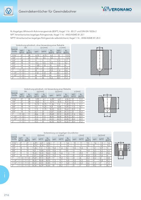
Gewindekernlöcher für GewindebohrerRc Kegeliges Whitworth-Rohrinnengewinde (BSPT), Kegel 1:16 - BS 21 und DIN EN 10226-2NPT Amerikanisches kegeliges Rohrgewinde, Kegel 1:16 - ANSI/ASME B1.20.1NPTF Amerikanisches kegeliges Rohrgewinde selbstdichtend, Kegel 1:16 - ANSI/ASME B1.20.3GewindeGrößeVorbohrung zylindrisch, ohne Verwendung einer ReibahleTPID1 [mm]t1 [mm]NPTNPTFRc(BSPT) NPT NPTFRc(BSPT)NPTNPTFRc(BSPT)1/16" 27 28 6,15 6,15 6,2 12 11,91/8" 27 28 8,5 8,5 8,2 12 11,91/4" 18 19 11 11 11 17,5 17,73/8" 18 19 14,5 14,5 14,5 17,6 18,11/2" 14 14 17,85 17,8 18 22,9 243/4" 14 14 23,2 23 23,5 23 25,31" 11 1/2 11 29 29 29,5 27,4 30,61 1/4" 11 1/2 11 37,8 37,8 38 28,1 32,91 1/2" 11 1/2 11 44 43,8 44 28,4 32,92" 11 1/2 11 56 56 55,5 28,4 37,2GewindeGrößeNPTNPTFVorbohrung zylindrisch, mit Verwendung einer ReibahleTPI D2 [mm] D3 [mm]t1 [mm]Rc(BSPT)NPTNPTFRc(BSPT) NPT NPTFRc(BSPT)NPTNPTFRc(BSPT)1/16" 27 28 5,95 6,1 6,39 6,41 6,56 12 11,91/8" 27 28 8,25 8,1 8,74 8,76 8,57 12 11,91/4" 18 19 10,75 10,75 11,36 11,4 11,45 17,5 17,73/8" 18 19 14,1 14,25 14,8 14,84 14,95 17,6 18,11/2" 14 14 17,5 17,75 18,32 18,33 18,63 22,9 243/4" 14 14 22,7 23 23,67 23,68 24,12 23 25,31" 11 1/2 11 28,6 29 29,69 29,72 30,29 27,4 30,61 1/4" 11 1/2 11 37,3 37,5 38,45 38,48 38,95 28,1 32,91 1/2" 11 1/2 11 43,4 43,5 44,52 44,55 44,85 28,4 32,92" 11 1/2 11 55,5 55 56,56 56,59 56,66 28,4 37,2Vorbereitung von kegeligen GrundlöcherTPID3 [mm]b [mm] t [mm] D4 [mm]GewindeGröße NPT RcNPTFRc(BSPT) NPT NPTFRcNPTFRcNPTF (BSPT) NPT(BSPT) NPT (BSPT) NPT NPTFRc(BSPT)1/16" 27 27 6,39 6,41 6,56 7 8 5,6 10 11 9,5 7,6 7,4 7,61/8" 27 27 8,74 8,76 8,57 7 8 5,6 10 11 9,5 10 9,8 9,61/4" 18 18 11,36 11,4 11,45 10,2 11,6 8,4 14,5 15,5 14 13,1 12,9 133/8" 18 18 14,8 14,84 14,95 10,6 12 8,8 15 16 14,4 16,5 16,3 16,51/2" 14 14 18,32 18,33 18,63 13,8 15,6 11,4 19 20,5 19 20,5 20,3 20,63/4" 14 14 23,67 23,68 24,12 14,2 16 12,7 20 21,5 20,3 25,8 25,6 261" 11 1/2 11 1/2 29,69 29,72 30,29 17 19,2 14,5 24 26 24,3 32,2 32 32,81 1/4" 11 1/2 11 1/2 38,45 38,48 38,95 17,5 19,7 16,8 24,5 26,5 26,6 41 40,8 40,21 1/2" 11 1/2 11 1/2 44,52 44,55 44,85 17,5 19,7 16,8 24,5 26,5 26,6 47,2 47 47,22" 11 1/2 11 1/2 56,56 56,59 56,66 18 20,2 21,1 25 27 30,9 59,2 59 58,7i216
Gewindekernlöcher für GewindeformerMetrisches ISO Regelgewinde DIN 13 Metrisches ISO Feingewinde DIN 13 Whitworth - Rohrgewinde EN - ISO 228MSteigung[mm]Kernlochbohrung[mm]M 2 0,4 1,85 ± 0,032,5 0,45 2,30 ± 0,033 0,5 2,80 ± 0,033,5 0,6 3,25 ± 0,034 0,7 3,70 ± 0,035 0,8 4,65 ± 0,036 1 5,55 ± 0,058 1,25 7,40 ± 0,0510 1,5 9,30 ± 0,0512 1,75 11,20 ± 0,0514 2 13,10 ± 0,0516 2 15,10 ± 0,0518 2,5 16,90 ± 0,0520 2,5 18,90 ± 0,0524 3 22,70 ± 0,0527 3 25,70 ± 0,0530 3,5 28,45 ± 0,05MFSteigung[mm]Kernlochbohrung[mm]M 3 0,35 2,85 ± 0,034 0,5 3,80 ± 0,035 0,5 4,80 ± 0,036 0,75 5,65 ± 0,038 1 7,55 ± 0,0510 1 9,55 ± 0,0510 1,25 9,40 ± 0,0512 1 11,55 ± 0,0512 1,25 11,40 ± 0,0512 1,5 11,30 ± 0,0514 1,25 13,40 ± 0,0514 1,5 13,30 ± 0,0516 1,5 15,30 ± 0,0518 1,5 17,30 ± 0,0520 1,5 19,30 ± 0,05GGangzahl auf1 ZollKernlochbohrung[mm]G 1/8" 28 9,25 ± 0,051/4" 19 12,50 ± 0,053/8" 19 16,00 ± 0,051/2" 14 20,00 ± 0,053/4" 14 25,50 ± 0,051" 11 32,00 ± 0,05Formel für die Berechnung der Gewindekernlöcher: d = Flanken Ø + Steigung / 5Zur Herstellung lehrenhaltiger Gewinde sind die entsprechenden Vorbohrdurchmesser und deren Toleranzen einzuhalten,unabdingbar, um auch die Gewindeausformung und Standzeiten der Werkzeuge zu erreichen.Der Gewinde-Kerndurchmesser ist in Abhängigkeit der Fließeigenschaften des zu bearbeitenden Werkstoffes zu sehen, und nichtnur mit dem vorgegebenen Vorbohrdurchmesser, wie dies beim Gewindeschneiden der Fall ist.Gewinde-Kerndurchmesser beim Gewindeformen prüft man mit 7H statt 6H beim Gewindeschneiden (für weitere Informationenverweisen wir auf die DIN 13 Teil 50).i217
- Seite 1 und 2:
Hauptkatalogvergnano.comNr. 54 - DE
- Seite 3 und 4:
Siehe Seite 10 ÷ 23 >WERKZEUGBESCH
- Seite 5 und 6:
EinleitungDas UnternehmenSeite.....
- Seite 7 und 8:
Vertrieb und ServiceSeit mehr als 2
- Seite 9 und 10:
Neue ProduktePISOPISOP30P K N SBP30
- Seite 11 und 12:
Werkzeug-Datenblatt ErklärungGewin
- Seite 13 und 14:
AAAAAAAAAAHSSEHSSEHSSEHSSEHSSEHSSEH
- Seite 15 und 16:
AAAPPPSSSAHSSEHSSEHSSEHSSPHSSPHSSPH
- Seite 17 und 18:
AAAAAAAAAAHSSEHSSKHSSKHSSEHSSEHSSEH
- Seite 19 und 20:
AAAAAPPPPPHSSEHSSEHSSEHSSEHSSEHSSPH
- Seite 21 und 22:
SSSHHHHAAAHSSKHSSKHSSKHMHMHMHMHSSEH
- Seite 23 und 24:
AAAPPSHHAAHSSKHSSKHSSEHSSPHSSPHSSKH
- Seite 25 und 26:
PPSSSHHHSSKHSSKHSSKHSSKHSSKHMHMC (2
- Seite 27 und 28:
AASERIE “A”Gewindebohrer für d
- Seite 29 und 30:
2,5 x DDIN 13HSSHANDGEWINDEBOHRER -
- Seite 31 und 32:
1,5 x DDIN 13HSSEMASCHINENGEWINDEBO
- Seite 34 und 35:
M1,5 x DDIN 13HSSEMASCHINENGEWINDEB
- Seite 36 und 37:
M2,5 x DDIN 13HSSEMASCHINENGEWINDEB
- Seite 38 und 39:
M2,5 x DDIN 13HSSKMASCHINENGEWINDEB
- Seite 40 und 41:
M2,5 x DDIN 13HSSEMASCHINENGEWINDEB
- Seite 42 und 43:
M2,5 x DDIN 13HSSEMASCHINENGEWINDEB
- Seite 44 und 45:
M2,5 x DDIN 13HSSEMASCHINENGEWINDEB
- Seite 46 und 47:
M2,5 x DDIN 13HSSEMASCHINENGEWINDEB
- Seite 48 und 49:
M2,5 x DDIN 13HSSEMASCHINENGEWINDEB
- Seite 50 und 51:
M1 x DDIN 13HSSEMASCHINENGEWINDEBOH
- Seite 52 und 53:
MR 151,5 x DDIN 13HSSEMASCHINENGEWI
- Seite 54 und 55:
MR 151,5 x DDIN 13HSSEMASCHINENGEWI
- Seite 56 und 57:
MR 402,5 x DDIN 13HSSEMASCHINENGEWI
- Seite 58 und 59:
MR 402,5 x DDIN 13HSSEMASCHINENGEWI
- Seite 60 und 61:
MR 402,5 x DDIN 13HSSEMASCHINENGEWI
- Seite 62 und 63:
MR 402,5 x DDIN 13HSSEMASCHINENGEWI
- Seite 64 und 65:
MR 402,5 x DDIN 13HSSEMASCHINENGEWI
- Seite 66 und 67:
MR 402,5 x DDIN 13HSSEMASCHINENGEWI
- Seite 68 und 69:
MR 4022,5 x DDIN 13HSSEMASCHINENGEW
- Seite 70 und 71:
MDIN 13HSSEMUTTERNMASCHINENGEWINDEB
- Seite 72 und 73:
M1,5 x DDIN 13HSSEMASCHINENGEWINDEF
- Seite 74 und 75:
M2,5 x DDIN 13HSSEMASCHINENGEWINDEF
- Seite 76 und 77:
MF2,5 x DDIN 13HSSHANDGEWINDEBOHRER
- Seite 78 und 79:
MF2,5 x DDIN 13HSSHANDGEWINDEBOHRER
- Seite 80 und 81:
MF1,5 x DDIN 13HSSEMASCHINENGEWINDE
- Seite 82 und 83:
MF1,5 x DDIN 13HSSEMASCHINENGEWINDE
- Seite 84 und 85:
MF1,5 x DDIN 13HSSEMASCHINENGEWINDE
- Seite 86 und 87:
MF2,5 x DDIN 13HSSEMASCHINENGEWINDE
- Seite 88 und 89:
MF2,5 x DDIN 13HSSEMASCHINENGEWINDE
- Seite 90 und 91:
MF2,5 x DDIN 13HSSEMASCHINENGEWINDE
- Seite 92 und 93:
MF2,5 x DDIN 13HSSEMASCHINENGEWINDE
- Seite 94 und 95:
MFR 151,5 x DDIN 13HSSEMASCHINENGEW
- Seite 96 und 97:
MFR 402,5 x DDIN 13HSSEMASCHINENGEW
- Seite 98 und 99:
MFDIN 13HSSEMUTTERNMASCHINENGEWINDE
- Seite 100 und 101:
MF1,5 x DDIN 13HSSEMASCHINENGEWINDE
- Seite 102 und 103:
MF2,5 x DDIN 13HSSEMASCHINENGEWINDE
- Seite 104 und 105:
UNC1,5 x D 1,5 x DHSSEMASCHINENGEWI
- Seite 106 und 107:
UNC2,5 x DHSSEMASCHINENGEWINDEBOHRE
- Seite 108 und 109:
UNCR 402,5 x DHSSEMASCHINENGEWINDEB
- Seite 110 und 111:
UNCR 4022,5 x DHSSEMASCHINENGEWINDE
- Seite 112 und 113:
UNF1,5 x D 1,5 x DHSSEMASCHINENGEWI
- Seite 114 und 115:
UNF2,5 x DHSSEMASCHINENGEWINDEBOHRE
- Seite 116 und 117:
UNFR 402,5 x DHSSEMASCHINENGEWINDEB
- Seite 118 und 119:
UNFR 4022,5 x DHSSEMASCHINENGEWINDE
- Seite 120 und 121:
8-UNR 402,5 x DHSSEMASCHINENGEWINDE
- Seite 122 und 123:
G1,5 x D 1,5 x DHSSEMASCHINENGEWIND
- Seite 124 und 125:
G2,5 x DHSSEMASCHINENGEWINDEBOHRER
- Seite 126 und 127:
GR 402,5 x DHSSEMASCHINENGEWINDEBOH
- Seite 128 und 129:
GR 402,5 x DHSSEMASCHINENGEWINDEBOH
- Seite 130 und 131:
Rp (BSPP)R 402,5 x DDIN EN10226-1HS
- Seite 132 und 133:
BSW2,5 x DBS84HSSHANDGEWINDEBOHRER
- Seite 134 und 135:
BSWR 151,5 x DBS84HSSEMASCHINENGEWI
- Seite 136 und 137:
NPTASMEB1.20.1HSSEMASCHINENGEWINDEB
- Seite 138 und 139:
NPTFASMEB1.20.3HSSEMASCHINENGEWINDE
- Seite 140 und 141:
M3 x D 3 x DDIN 13HSSPHOCHLEISTUNGS
- Seite 142 und 143:
MR 152 x DDIN 13HSSPHOCHLEISTUNGSMA
- Seite 144 und 145:
MR453 x DDIN 13HSSZHOCHLEISTUNGSMAS
- Seite 146 und 147:
M1,5 x DDIN 13HSSKHOCHLEISTUNGSMASC
- Seite 148 und 149:
M1,5 x D 3 x DE (1,5-2)DIN 13HSSKHO
- Seite 150 und 151:
M3 x DDIN 13HSSKHOCHLEISTUNGSMASCHI
- Seite 152 und 153:
MFR 152 x DDIN 13HSSPHOCHLEISTUNGSM
- Seite 154 und 155:
MF1,5 x D3 x DDIN 13HSSKHOCHLEISTUN
- Seite 156 und 157:
GR453 x DHSSZHOCHLEISTUNGSMASCHINEN
- Seite 158 und 159:
156A150 TiX2
- Seite 160 und 161:
M3 x D 3 x DDIN 13HSSK SMASCHINENGE
- Seite 162 und 163:
MR 403 x DDIN 13HSSK SMASCHINENGEWI
- Seite 164 und 165:
MF3 x DDIN 13HSSK SMASCHINENGEWINDE
- Seite 166 und 167:
MFR 403 x DDIN 13HSSK SMASCHINENGEW
- Seite 168 und 169: M2,5 x DDIN 13HMVHM-MASCHINENGEWIND
- Seite 170 und 171: M1,5 x DDIN 13HMVHM-MASCHINENGEWIND
- Seite 172 und 173: MF2,5 x DDIN 13HMVHM-MASCHINENGEWIN
- Seite 174 und 175: 172P180 N TiN
- Seite 176 und 177: MDIN 13HSSSCHNEIDEISEN mit Schälan
- Seite 178 und 179: MFDIN 13HSSSCHNEIDEISEN mit Schäla
- Seite 180 und 181: UNFHSSSCHNEIDEISEN mit Schälanschn
- Seite 182 und 183: BSWBS84HSSSCHNEIDEISEN mit Schälan
- Seite 184 und 185: 200BP43 ACE
- Seite 186 und 187: M2,5 x DDIN 13HSSEMASCHINENGEWINDEB
- Seite 188 und 189: M2,5 x DDIN 13HSSZMASCHINENGEWINDEB
- Seite 190 und 191: ML 152,5 x DDIN 13HSSEMASCHINENGEWI
- Seite 192 und 193: MR 402,5 x DDIN 13HSSKMASCHINENGEWI
- Seite 194 und 195: MR 252,5 x DDIN 13HSSZMASCHINENGEWI
- Seite 196 und 197: MFL 152,5 x DDIN 13HSSEMASCHINENGEW
- Seite 198 und 199: MFR 402,5 x DDIN 13HSSKMASCHINENGEW
- Seite 200 und 201: UNF2,5 x DHSSEMASCHINENGEWINDEBOHRE
- Seite 202 und 203: 190P30 TiN
- Seite 204 und 205: Aufbau Gewindebohrer und Schneideis
- Seite 206 und 207: Anschnittformen und ZentrierartenAn
- Seite 208 und 209: Werkzeugstähle für die Gewindeboh
- Seite 210 und 211: Mögliche Fehler oder Probleme bei
- Seite 212 und 213: FormelnParameter Formel EinheitSchn
- Seite 214 und 215: Werkstoff BeispieleiISO513PStahlMRo
- Seite 216 und 217: Gewindekernlöcher für Gewindebohr
- Seite 220 und 221: Toleranzfeld Maschinengewindebohrer
- Seite 222 und 223: SymbolerklärungGEWINDEBOHRER MAßE
- Seite 224 und 225: SymbolerklärungANSCHNITTFORMANWEND
- Seite 226 und 227: ARTIKEL INDEXA A AARTIKEL-NR. Gewin
- Seite 228 und 229: Graphik:StudioAlmayernChieri - Tori