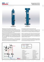
Flüssigkeitsabscheider Suction Line Accumulators - ESK Schultze
Flüssigkeitsabscheider Suction Line Accumulators - ESK Schultze
Flüssigkeitsabscheider Suction Line Accumulators - ESK Schultze

Erfolgreiche ePaper selbst erstellen
Machen Sie aus Ihren PDF Publikationen ein blätterbares Flipbook mit unserer einzigartigen Google optimierten e-Paper Software.
� Visit our website: www.esk-schultze.de<br />
Allgemeines<br />
Kältemittelverdichter haben die Aufgabe, das Kältemittel dampfförmig<br />
anzusaugen und auf die für die Verflüssigung entsprechenden Bedingungen<br />
zu verdichten. Anlagen- und temperaturbedingt können jedoch<br />
Zustände auftreten, die Kältemittel in noch flüssiger Form zum Verdichter<br />
zurückführen. Sogenannte Flüssigkeitsschläge mit nachstehendem<br />
Schadensbild am Verdichter sind die Folgen:<br />
� Zerstörte Saugventile � Dichtungsbruch<br />
� Lagerschäden � Kolben- und Pleuelbrüche<br />
� Zerstörte Druckventile<br />
<strong>ESK</strong>-FIüssigkeitsabscheider werden nach dem seit Jahrzehnten bewährten<br />
Injektorprinzip gebaut, das auch bei aufgefüllten Abscheidern das Ansaugen<br />
von Flüssigkeit verhindert.<br />
Anwendung<br />
Bei Kompaktanlagen mit zu geringer Sauggasüberhitzung dT < 7K (Rückstrom<br />
von unverdampften FIüssigkeitströpfchen) ergeben sich durch das<br />
Verhalten von Öl-/Kältemittel Öldruckprobleme und erhebliche Leistungsminderungen<br />
der Anlage. <strong>ESK</strong>-<strong>Flüssigkeitsabscheider</strong> schützen Verdichter<br />
und Anlagen vor Flüssigkeitsschlägen und Betriebsstörungen. Der Einsatz<br />
wird bei folgenden Kriterien dringend empfohlen:<br />
� Verbundanlagen � Flüssigkeitsverlagerung<br />
� Transportkühlung � Überflutete Verdampfer<br />
� Heißgasabtauung � Umschaltbare Systeme<br />
� Containerkühlung � Sauggasüberhitzung < 7K<br />
Technische Spezifikation<br />
<strong>ESK</strong>-<strong>Flüssigkeitsabscheider</strong> sind für den Einsatz mit HFKW- und HFCKW-<br />
Kältemitteln (R134a, R404A, R507, R407A, R407C, R22 etc.) freigegeben.<br />
Durch die saugseitige Anwendung können die <strong>Flüssigkeitsabscheider</strong> auch<br />
für R410A eingesetzt werden. Auf Anfrage werden die <strong>Flüssigkeitsabscheider</strong><br />
auch für natürliche Kältemittel (R717, R290) freigegeben.<br />
Max. zulässiger Betriebsüberdruck [bar] 28 20<br />
Zulässige Betriebstemperatur [°C] 100 ...–10 –10 ... –50<br />
18<br />
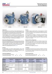
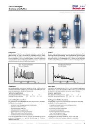
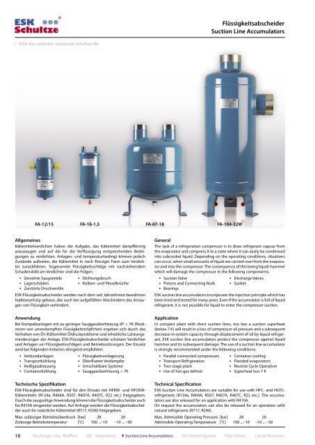
FA-12/15 FA-16-1,5 FA-67-18 FA-104-32W<br />
<strong>Flüssigkeitsabscheider</strong><br />
<strong>Suction</strong> <strong>Line</strong> <strong>Accumulators</strong><br />
General<br />
The task of a refrigeration compressor is to draw refrigerant vapour from<br />
the evaporator and compress it to a state where it can easily be condensed<br />
into subcooled liquid. Depending on the operating conditions, situations<br />
can occur, when small amounts of liquid are carried-over from the evaporator<br />
and into the compressor. The consequence of this being liquid-hammer<br />
which will damage the compressor in the following components:<br />
� <strong>Suction</strong> Valve � Discharge Valves<br />
� Pistons and Connecting Rods � Gasket<br />
� Bearings<br />
<strong>ESK</strong> suction line accumulators incorporate the injection principle which has<br />
been tried and tested for many years. Even if the accumulator is full of liquid<br />
refrigerant, it is not possible for liquid to enter the compressor suction.<br />
Application<br />
In compact plant with short suction lines, too low a suction superheat<br />
(below 7 K) will result in a loss of compressor oil pressure and a subsequent<br />
decrease in system capacity through displacement of oil by liquid refrigerant.<br />
<strong>ESK</strong> suction line accumulators protect the compressor against liquid<br />
hammer and its subsequent damage. The use of a suction line accumulator<br />
is strongly recommended under the following conditions:<br />
� Parallel connected compressors � Container cooling<br />
� Transport Refrigeration � Flooded evaporators<br />
� Two-stage plant � Reverse Cycle Operation<br />
� Use of hot-gas defrost � Superheat less 7 K<br />
Technical Specification<br />
<strong>ESK</strong>-<strong>Suction</strong> <strong>Line</strong> <strong>Accumulators</strong> are suitable for use with HFC- and HCFCrefrigerants<br />
(R134a, R404A, R507, R407A, R407C, R22 etc.). The accumulators<br />
are also released for an application with R410A.<br />
On request the accumulators can also be released for an operation with<br />
natural refrigerants (R717, R290).<br />
Max. Admissible Operating Pressure [bar] 28 20<br />
Admissible Operating Temperature [°C] 100 ...–10 –10 ... –50<br />
Discharge <strong>Line</strong> Mufflers Oil Separators � <strong>Suction</strong> <strong>Line</strong> <strong>Accumulators</strong> Oil Control System Filter Driers Liquid Receivers
<strong>Flüssigkeitsabscheider</strong><br />
<strong>Suction</strong> <strong>Line</strong> <strong>Accumulators</strong><br />
Auswahlgrundsätze<br />
Für die Auslegung sind die folgenden Kriterien maßgebend:<br />
1. Die Relation zwischen Anlagenfüllmenge und Abscheidervolumen:<br />
Verdichterhersteller empfehlen den Abscheider so zu bemessen, dass<br />
ca. 50 bis 70 % der Anlagenfüllmenge vom Abscheider aufgenommen<br />
werden können.<br />
2. Die Sauggasgeschwindigkeit Csl min > 7 m/s sichert die Ölrückführung<br />
aus dem Abscheider.<br />
Csl opt. = 14 m/s begrenzt den Druckabfall auf der Saugseite. Bei kurzen<br />
Saugleitungen (2 bis 5 m) kann der Optimalwert – opt. – überschritten<br />
werden. In der Leistungstabelle werden die Kälteleistungsdaten für Csl<br />
min. und Csl opt. dokumentiert. Bei Leistungsregelung von Verdichtern<br />
kann die als min. bezeichnete Angabe um bis zu 20 % unterschritten<br />
werden (Grenzwert).<br />
Multi <strong>Flüssigkeitsabscheider</strong><br />
<strong>ESK</strong>-Multiflüssigkeitsabscheider für maximal vier Verdichter werden anstelle<br />
von mehreren einzelnen <strong>Flüssigkeitsabscheider</strong>n oder individuell gestalteten<br />
Saugsammelleitungen in die Haupt-Saugleitung von Verbundsystemen<br />
eingesetzt. Jeder Verdichter wird auf einfache Weise strömungssymmetrisch<br />
korrekt angeschlossen. Durch das Injektorprinzip wird bei richtiger<br />
Zuordnung die einwandfreie Ölrückführung gewährleistet.<br />
Multiflüssigkeitsabscheider vermeiden fehlerhafte Installationen und verringern<br />
die Montagekosten. Bei Teillastbetrieb ist die Gasgeschwindigkeit<br />
in der Hauptsaugleitung zu beachten.<br />
Verdampfungstemperatur Kältemittel Bemerkung<br />
Evaporating temperature Refrigerant Remark<br />
to °C von/from to °C bis/to<br />
QUALITY PRODUCTS · MADE IN GERMANY<br />
Selection<br />
For dimensioning suction line accumulators the following points must be<br />
considered:<br />
1. Relationship between accumulator volume and refrigerant charge.<br />
Compressor manufacturers recommend that 50 to 70 percent of the<br />
system charge should be able to fit into the accumulator.<br />
2. The suction gas velocity, Csl where, Csl, min. > 7m/s ensures oil return.<br />
Csl, opt. = 14 m/s limits suction pressure drop. In installations with short<br />
suction lines (2 to 5 m) capacity can be higher than optimum value – opt.<br />
When capacity regulation is used, the Csl, min. values can be decreased<br />
by 20 % (absolut limit).<br />
Multi <strong>Suction</strong> <strong>Line</strong> <strong>Accumulators</strong><br />
<strong>ESK</strong> multi suction line accumulators can be used where several, individual suction<br />
line accumulators would normally be required. They may also be used for<br />
individually designed suction lines prior to the main suction line for parallel<br />
connected compressors. Each compressor is quite easily connected through<br />
separate suction circuits that should all produce the same pressure drop.<br />
<strong>ESK</strong> multi suction line accumulators help to avoid unnecessary installation<br />
work and hence reduce system costs. Under part load conditions, the gas<br />
velocity should be considered.<br />
Temperaturgrenzen Temperature Limits<br />
+ 10 – 15 R134a, R404A, R407A, R407C, R410A, R507, R22 Alle Ausführungen einsetzbar / all versions suitable<br />
– 15 – 50 R134a, R404A, R407A, R407C, R410A, R507, R22<br />
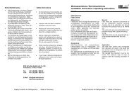
Installation<br />
FA ..W <strong>Flüssigkeitsabscheider</strong><br />
<strong>Suction</strong> <strong>Line</strong> Accumulator<br />
Nur FA ..W oder FA .. bzw. MA .. mit Heizelementen<br />
Ölabscheider in der Druckleitung (5) erforderlich<br />
Only FA ..W or FA .., MA .. with heater elements<br />
Oil separator in discharge side (5) necessary<br />
Legende – Installation Legend – Installation<br />
FA ..W und MA ..Multi FA ..W and MA ..Multi<br />
1 vom Verdampfer from Evaporator<br />
2 zum Verdichter to Compressor<br />
2.2 Absaugdüse mit Saugrohr Nozzle with <strong>Suction</strong> Tube<br />
3 Vibrationsabsorber Vibration Eliminator<br />
4 Verdichter Compressor<br />
5 zum Verflüssiger to Condenser<br />
6 <strong>ESK</strong> Ölreguliersystem <strong>ESK</strong> Oil Control System<br />
erforderlich (siehe Schaltbilder) necessary (see diagrams)<br />
7 Flüssigkeitseintritt, -austritt; Liquid Inlet, -Outlet<br />
Wärmetauscher Heat Exchanger<br />
Flüssigkeitstemperatur >20 °C Liquid Temperature >20 °C<br />
ILC Intelligent Level Control Sight Glasses R717-Recommendations Components for CO2 Accessories Spare Parts<br />
19
� Visit our website: www.esk-schultze.de<br />
20<br />
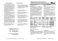
Installation MA ..Multi<br />
1 vom Verdampfer from Evaporator<br />
2 zum Verdichter to Compressor<br />
2.2 Absaugdüse mit Saugrohr Nozzle with <strong>Suction</strong> Tube<br />
3 Vibrationsabsorber Vibration Eliminator<br />
4 Verdichter Compressor<br />
5 zum Verflüssiger to Condenser<br />
6 <strong>ESK</strong> Ölreguliersystem <strong>ESK</strong> Oil Control System<br />
erforderlich (siehe Schaltbilder) necessary (see diagrams)<br />
Montage, a<br />
nur vertikal!<br />
Vertical<br />
mounting only!<br />
Multi <strong>Flüssigkeitsabscheider</strong><br />
Multi <strong>Suction</strong> <strong>Line</strong> <strong>Accumulators</strong><br />
Auslegungsdaten Selection Data<br />
Multiabscheider Kälteleistung Q0 [kW] pro Verdichter Effektives<br />
bei 40 °C Verflüssigungstemperatur und 25 °C Sauggastemperatur Förder-<br />
Verdampfungstemperatur [°C], einstufiger Betrieb volumen<br />
Multi Accumulator Ref. Capacity Q0 [kW] for each Compressor Effective<br />
at 40 °C Condensing temperature and 25 °C <strong>Suction</strong>gas temperature Displace-<br />
Evaporating temperature [°C], single stage operation ment<br />
R 404A, R 407A, R 407 C, R 507, R 22 R 410 A R 134 a Vo<br />
Typ / Type +5 0 –5 –10 –15 –20 –25 – 30 – 35 – 40 + 5 – 5 –15 –25 + 5 –10 – 20 – 30 m³ / h<br />
MA-35-42-54/4x22 Opt. 17,0 15,0 12,6 10,6 8,3 7,0 5,6 4,6 3,8 2,9 25,0 18,0 12,0 8,4 10,2 5,6 3,6 2,4 15,8<br />
Min. 8,5 7,5 6,3 5,3 4,2 3,6 3,0 2,3 1,9 1,5 12,5 9,0 6,0 4,2 5,1 2,8 1,8 1,2 7,9<br />
MA-42-54/4 x 28 Opt. 26,7 23,0 19,0 16,0 13,0 11,0 8,8 7,2 5,8 4,5 38,4 28,0 20,0 13,0 17,5 9,8 6,4 4,0 24,8<br />
MA-67/4 x 28 Min. 13,4 11,5 9,5 8,0 6,5 5,5 4,5 3,6 2,9 2,3 19,2 14,0 10,0 6,5 8,7 4,9 3,2 2,0 12,4<br />
MA-67/4 x 35 Opt. 44,0 36,0 32,0 26,0 22,0 18,0 14,0 12,0 10,0 8,0 64,0 46,0 32,0 22,0 26,8 15,0 9,8 6,2 40,6<br />
Min. 22,0 18,0 16,0 13,0 11,0 9,0 7,0 6,0 5,0 4,0 32,0 23,0 16,0 11,0 13,4 7,5 4,9 3,1 20,3<br />
MA-80/4 x 42 Opt. 62,0 52,0 46,0 36,0 30,0 25,0 20,0 16,0 14,0 10,0 94,0 66,0 46,0 32,0 40,0 22,0 14,0 9,0 57,2<br />
Min. 31,0 26,0 23,0 18,0 15,0 13,0 10,0 8,0 7,0 5,0 47,0 33,0 23,0 16,0 20,0 11,0 7,0 4,5 28,6<br />
Einsatz nur mit Heizelementen<br />
Application with heater elements only<br />
Technische Daten Technical Data<br />
Multi Flüssigkeits- Abb. Eintritt Austritt Inhalt Abmessungen Gewicht DRL<br />
abscheider Lötanschluss innen Lötanschluss innen<br />
Multi <strong>Suction</strong> <strong>Line</strong> Fig. Inlet Solder Outlet Solder Volume Dimensions Weight PED<br />
Accumulator Connection O.D.S Connection O.D.S.<br />
Typ / Type Ø SL Ø SL Ø SL Ø SL Ø D H R M Kategorie/Modul<br />
mm inch mm inch l (dm³) mm mm kg Category/Module<br />
MA-35/4 x 22 a 35 1-3/8 4 x 22 4 x 1-7/8 7,5 200 345 5/8”–18UNF M10 6,2 II / A1<br />
MA-42/4 x 22 a 42 1-5/8 4 x 22 4 x 1-7/8 7,5 200 385 5/8”–18UNF M10 6,2 II / A1<br />
MA-54/4 x 22 a 54 2-1/8 4 x 22 4 x 1-7/8 7,5 200 358 5/8”–18UNF M10 6,2 II / A1<br />
MA-42/4 x 28 a 42 1-5/8 4 x 28 4 x 1-1/8 7,5 200 385 5/8”–18UNF M10 6,2 II / A1<br />
MA-54/4 x 28 a 54 2-1/8 4 x 28 4 x 1-1/8 7,5 200 358 5/8”–18UNF M10 6,2 II / A1<br />
MA-67/4 x 28 a 67 2-5/8 4 x 28 4 x 1-1/8 18,0 300 405 5/8”–18UNF M12 15,0 II / A1<br />
MA-67/4 x 35 a 67 2-5/8 4 x 35 4 x 1-3/8 18,0 300 405 5/8”–18UNF M12 15,0 II / A1<br />
MA-80/4 x 42 a 80 3-1/8 4 x 42 4 x 1-3/8 18,0 300 410 5/8”–18UNF M12 15,0 II / A1<br />
Ø SL = Saugleitungs-Außendurchmesser Ø SL = <strong>Suction</strong> <strong>Line</strong> Outside Diameter<br />
Maßzeichnung Dimensional Drawing<br />
Discharge <strong>Line</strong> Mufflers Oil Separators � <strong>Suction</strong> <strong>Line</strong> <strong>Accumulators</strong> Oil Control System Filter Driers Liquid Receivers
<strong>Flüssigkeitsabscheider</strong><br />
<strong>Suction</strong> <strong>Line</strong> <strong>Accumulators</strong><br />
QUALITY PRODUCTS · MADE IN GERMANY<br />
Auslegungsdaten Selection Data<br />
Flüssigkeits- Kälteleistung Q0 [kW] Effektives<br />
abscheider bei 40 °C Verflüssigungstemperatur und 25 °C Sauggastemperatur Förder-<br />
Anschlussgröße Verdampfungstemperatur [°C], einstufiger Betrieb volumen<br />
<strong>Suction</strong> <strong>Line</strong>- Ref. Capacity Q0 [kW] Effective<br />
Accumulator at 40 °C Condensing Temperature and 25°C <strong>Suction</strong>gas temperature Displace-<br />
Connection Size Evaporating temperature [°C], single stage operation ment<br />
Ø SL Ø SL Typ / Type R 404 A, R 407A, R 407 C, R 507, R 22 R 410 A R134 a Vo<br />
mm inch +5 0 –5 –10 –15 –20 –25 –30 –35 –40 +5 –5 –15 –25 +5 –10 –20 –30 m³/h<br />
12 – FA-12/15 Opt. 4,3 3,8 3,2 2,6 2,1 1,7 1,4 1,2 1,0 0,7 6,0 4,4 3,0 2,0 2,8 1,6 1,0 0,6 4,0<br />
Min. 2,2 1,9 1,6 1,3 1,1 0,9 0,7 0,6 0,5 0,4 3,0 2,2 1,5 1,0 1,4 0,8 0,5 0,3 2,0<br />
15 – FA-12/15 Opt. 7,1 6,2 5,4 4,6 3,5 2,9 2,4 1,9 1,6 1,2 10,4 7,4 5,2 3,6 4,7 2,6 1,8 1,1 6,6<br />
Min. 3,6 3,1 2,7 2,3 1,8 1,5 1,2 1,0 0,8 0,6 5,2 3,7 2,6 1,8 2,4 1,3 0,9 0,5 3,3<br />
16 5/8 FA-16… Opt. 8,4 7,6 6,4 5,2 4,1 3,3 2,8 2,3 2,0 1,4 12,0 8,6 6,0 4,0 5,5 3,0 2,0 1,2 7,8<br />
Min. 4,2 3,8 3,2 2,6 2,1 1,7 1,4 1,2 1,0 0,7 6,0 4,3 3,0 2,0 2,8 1,5 1,0 0,6 3,9<br />
18 – FA-18… Opt. 10,9 9,0 7,4 6,0 4,9 4,0 3,2 2,5 2,2 1,6 15,6 10,8 7,4 5,0 7,0 3,8 2,4 1,5 10,2<br />
Min. 5,5 4,5 3,7 3,0 2,5 22,0 1,6 1,3 1,1 0,8 7,8 5,4 3,7 2,5 3,5 1,9 1,2 0,8 5,1<br />
22 7/8 FA-22… Opt. 17,0 15,0 12,6 10,6 8,3 7,0 5,5 4,6 3,8 2,9 25,0 18,0 12,0 8,4 10,2 5,6 3,6 2,4 15,8<br />
Min. 8,5 7,5 6,3 5,3 4,2 3,6 3,0 2,3 1,9 1,5 12,5 9,0 6,0 4,2 5,1 2,8 1,8 1,2 7,9<br />
28 1-1/8 FA-28… Opt. 26,7 23,0 19,0 16,0 13,0 11,0 8,8 7,2 5,8 4,5 38,4 28,0 20,0 13,0 17,5 9,8 6,4 4,0 24,8<br />
Min. 13,4 11,5 9,5 8,0 6,5 5,5 4,5 3,6 2,9 2,3 19,2 14,0 10,0 6,5 8,7 4,9 3,2 2,0 12,4<br />
35 1-3/8 FA-35… Opt. 44 36 32 26 22 18 14,0 12 10 8 64 46 32 22 26,8 15,0 9,8 6,2 40,6<br />
Min. 22 18 16 13 11 9 7,0 6 5 4 32 23 16 11 13,4 7,5 4,9 3,1 20,3<br />
42 1-5/8 FA-42… Opt. 62 52 46 36 30 25 20 16 14 10 94 66 46 32 40 22 14 9,0 57,2<br />
Min. 31 26 23 18 15 13 10 8 7 5 47 33 23 16 20 11 7 4,5 28,6<br />
54 2-1/8 FA-54… Opt. 107 92 76 64 52 43 35 28 24 18 154 110 76 52 70 40 26 16 99,0<br />
Min. 53 46 38 32 26 22 18 14 12 9 77 55 38 26 35 20 13 8 49,5<br />
64 2-1/2 FA-67/64… Opt. 153 128 108 90 75 62 50 42 34 26 220 158 110 76 100 56 36 24 142<br />
Min. 77 64 54 45 38 31 25 21 17 13 110 79 55 38 50 28 18 12 71<br />
67 2-5/8 FA-67… Opt. 168 142 122 100 84 72 58 48 38 30 244 174 122 84 108 62 40 26 148<br />
Min. 84 71 61 50 42 36 29 24 19 15 122 87 61 42 54 31 20 13 74<br />
70 2-3/4 FA-67/70… Opt. 180 154 132 108 90 76 62 50 40 32 268 192 134 92 114 66 44 28 163,0<br />
Min. 90 77 66 54 45 38 31 25 20 16 134 96 67 46 57 33 22 14 81,5<br />
80 3-1/8 FA-80… Opt. 240 208 176 146 124 104 84 70 56 44 356 254 178 122 158 89 58 36 218<br />
Min. 120 104 89 73 62 52 42 35 28 22 178 127 89 61 79 45 29 18 109<br />
89 3-1/2 FA-80/89… Opt. 310 266 226 188 158 132 108 88 72 56 444 318 222 152 202 114 74 48 270<br />
Min. 155 133 113 94 79 66 54 44 36 28 222 159 111 76 101 57 37 24 135<br />
104 4-1/8 FA-104… Opt. 430 360 304 256 210 172 140 116 92 73 600 430 300 200 270 152 98 62 400<br />
Min. 215 180 152 128 105 86 70 58 46 37 300 215 150 100 135 76 49 31 200<br />
Ø SL = Saugleitungs-Außendurchmesser Einsatz nur mit Wärmetauscher oder Heizelementen<br />
<strong>Suction</strong> <strong>Line</strong> Outside Diameter Application with heat exchanger or heater elements only<br />
Auslegungsbeispiele Examples of Selection<br />
Beispiel Verdichter Verdichter Leistungs- Verd.- Auswahlkriterien <strong>ESK</strong>-Produkt<br />
Anschluss regelung temp.<br />
Example Compressor Compressor Capacity- Evap.- Selection, Information <strong>ESK</strong>-Product<br />
Connection Control temp.<br />
VH Ø SL Ø SL auf / to to<br />
No. m³/h mm inch % °C<br />
1 13 22 7/8 – –20<br />
R407A; Kälteleistung Qo = 4,7 kW;<br />
R407A; Capacity Qo = 4,7 kW<br />
FA-22W<br />
2 50 35 1-3/8 66 +5<br />
Pc/Po = 2,6; λ = 0,9; Vo = 0,9 x 50 = 45 m³ / h,<br />
Vo min = 30 m³ / h<br />
FA-42<br />
3 126 54 2-1/8 – –5<br />
90 kg R 22; Kälteleistung Qo = 83 kW<br />
90 kg R 22; Capacity Qo = 83 kW<br />
FA-67-32<br />
4 71 35 1-3/8 – – 40<br />
Verdichter zweistufig / Compressor two stage<br />
VHL = 71 m³ /h; Vo = VHL x 0,85 = 60 m³ /h<br />
FA-54WT oder / or<br />
FA-54-7W<br />
Verdichter, einstufig VO = λ x VH<br />
Compressor, single stage<br />
Verdichter, zweistufig VO = 0,85 x VHL<br />
Compressor, two stage<br />
VHL = Hubvolumen, Niederdruckstufe<br />
Displacement, low stage<br />
P/P 0 : Druckverhältnis Pressure ratio<br />
V0 : Effektives Fördervolumen Effective displacement<br />
VH : Theoretisches Hubvolumen Compressor displacement<br />
λ : Liefergrad Volumetric efficiency<br />
ILC Intelligent Level Control Sight Glasses R717-Recommendations Components for CO2 Accessories Spare Parts<br />
21
� Visit our website: www.esk-schultze.de<br />
Flüssigkeits- Abb. Lötanschluss Inhalt Abmessungen Gewicht DRL<br />
abscheider Innen<br />
<strong>Suction</strong> <strong>Line</strong>- Fig. Solder Connection Volume Dimensions Weight PED<br />
Acculmulator O. D. S.<br />
Typ Ø SL Ø SL Ø D H A W Z M Kat./Modul<br />
Type mm inch l (dm³) mm mm mm mm mm kg Cat./Module<br />
22<br />
FA-12/15 a 12 1/2 0,3 58 140 95 – – – 0,6 –<br />
FA-16-1,5 b 16 5/8 1,5 108 250 60 – – M10 2,0 –<br />
FA-16-2 b 16 5/8 2,0 108 320 60 – – M10 2,5 I / A<br />
FA-16 c 16 5/8 2,3 125 254 60 – – M10 2,0 I / A<br />
FA-18-2 b 18 – 2,0 108 289 60 – – M10 2,5 I / A<br />
FA-22-2 b 22 7/8 2,0 108 329 60 – – M10 2,7 I / A<br />
FA-22 c 22 7/8 3,5 125 387 60 – – M10 2,7 I / A<br />
FA-22-7 c 22 7/8 7,1 195 321 100 – – M10 6,0 I / A<br />
FA-28-2 b 28 1-1/8 2,0 108 336 60 – – M10 2,9 I / A<br />
FA-28 c 28 1-1/8 3,5 125 392 60 – – M10 2,9 I / A<br />
FA-28-7 c 28 1-1/8 7,5 200 327 100 – – M10 6,0 II / A1<br />
FA-35 c 35 1-3/8 7,5 200 332 100 – – M10 6,0 II / A1<br />
FA-42 c 42 1-5/8 7,5 200 335 100 – – M10 6,0 II / A1<br />
FA-54-7 c 54 2-1/8 7,5 200 340 100 – – M10 6,5 II / A1<br />
FA-54-9 c 54 2-1/8 9,5 200 417 100 – – M10 7,5 II / A1<br />
FA-54T d 54 2-1/8 2 x 7,5 200 359 300 – 300 M12 12,5 II / A1<br />
FA-67/64T d 64 2-1/2 2 x 7,5 200 401 300 – 300 M12 14,0 II / A1<br />
FA-67T d 67 2-5/8 2 x 7,5 200 364 300 – 300 M12 13,0 II / A1<br />
FA-67/70T d 70 2-3/4 2 x 7,5 200 410 300 – 300 M12 14,0 II / A1<br />
FA-67-18 e 67 2-5/8 18 300 468 150 300 – 18,0 II / A1<br />
FA-80 e 80 3-1/8 18 300 471 150 – 300 – 18,0 II / A1<br />
FA-80/89 e 89 3-1/2 18 300 530 150 – 300 – 19,0 II / A1<br />
FA-54-32 f 54 2-1/8 32 273 838 231 – 294 – 41,1 II / A1<br />
FA-67-32 f 67 2-5/8 32 273 804 197 – 294 – 36,3 II / A1<br />
FA-80-32 f 80 3-1/8 32 273 854 262 – 294 – 41,7 II / A1<br />
FA-89-32 f 89 3-1/2 32 273 854 262 – 294 – 41,7 II / A1<br />
FA-104-32 f 104 4-1/8 32 273 812 221 – 294 – 39,2 II / A1<br />
FA-104-64T – 104 4-1/8 2x32 Auf Anfrage / On Request 84,4 II / A1<br />
Ø SL = Saugleitungs-Außendurchmesser Ø SL = <strong>Suction</strong> <strong>Line</strong> Outside Diameter<br />
<strong>Flüssigkeitsabscheider</strong><br />
<strong>Suction</strong> <strong>Line</strong> <strong>Accumulators</strong><br />
Technische Daten Technical Data<br />
a b c d e f<br />
Discharge <strong>Line</strong> Mufflers Oil Separators � <strong>Suction</strong> <strong>Line</strong> <strong>Accumulators</strong> Oil Control System Filter Driers Liquid Receivers
<strong>Flüssigkeitsabscheider</strong> mit Wärmetauscher<br />
<strong>Suction</strong> <strong>Line</strong> <strong>Accumulators</strong> with Heat exchanger<br />
QUALITY PRODUCTS · MADE IN GERMANY<br />
Technische Daten Technical Data<br />
Flüssigkeits- Abb. Lötanschluss Inhalt Lötanschluss Abmessungen Gewicht DRL<br />
abscheider Innen Wärmeaustauscher<br />
<strong>Suction</strong> <strong>Line</strong>- Fig. Solder Connection Volume Solder Connection Dimensions Weight PED<br />
Acculmulator O. D. S. Heat exchanger<br />
Typ Ø SL Ø SL Ø FL Ø FL Ø D H A W Z M Kat./Modul<br />
Type mm inch l (dm³) mm inch mm mm mm mm mm kg Cat./Module<br />
FA-16W a 16 5/8 2,3 16 5/8 125 274 60 80 – M10 2,5 I / A<br />
FA-22W a 22 7/8 3,5 16 5/8 125 395 60 80 – M10 3,2 I / A<br />
FA-28W a 28 1-1/8 3,5 16 5/8 125 395 60 80 – M10 3,4 I / A<br />
FA-35W a 35 1-3/8 7,5 22 7/8 200 339 100 140 – M10 7,0 II / A1<br />
FA-42W a 42 1-5/8 7,5 22 7/8 200 339 100 140 – M10 7,3 II / A1<br />
FA-54-7W a 54 2-1/8 7,5 22 7/8 200 339 100 140 – M10 8,0 II / A1<br />
FA-54-9W a 54 2-1/8 9,0 22 7/8 195 420 100 140 – M10 9,0 II / A1<br />
FA-54WT b 54 2-1/8 2 x 7,5 22 7/8 200 361 300 140 300 M12 13,5 II / A1<br />
FA-67/64WT b 64 2-1/2 2 x 7,5 22 7/8 200 400 300 140 300 M12 14,0 II / A1<br />
FA-67WT b 67 2-5/8 2 x 7,5 22 7/8 200 363 300 140 300 M12 15,0 II / A1<br />
FA-67-18W c 67 2-5/8 18 22 7/8 300 468 150 140 300 – 19,0 II / A1<br />
FA-80W c 80 3-1/8 18 22 7/8 300 471 150 140 300 – 19,0 II / A1<br />
FA-80/89W c 89 3-1/2 18 22 7/8 300 530 150 140 300 – 20,0 II / A1<br />
FA-54-32W d 54 2-1/8 32 16 5/8 273 838 231 105 294 – 43,4 II / A1<br />
FA-67-32W d 67 2-5/8 32 16 5/8 273 804 197 105 294 – 38,6 II / A1<br />
FA-80-32W d 80 3-1/8 32 16 5/8 273 854 262 105 294 – 44,0 II / A1<br />
FA-89-32W d 89 3-1/2 32 16 5/8 273 854 262 105 294 – 44,0 II / A1<br />
FA-104-32W d 104 4-1/8 32 16 5/8 273 812 221 105 294 – 41,5 II / A1<br />
FA-104-64WT – 104 4-1/8 2x32 16 5/8 Auf Anfrage / On Request 89,0 II / A1<br />
Ø SL = Saugleitungs-Außendurchmesser Ø FL = Flüssigkeitsleitung Ø SL = <strong>Suction</strong> <strong>Line</strong> Outside Diameter Ø FL = Liquid <strong>Line</strong><br />
a b c d<br />
1) Wärmetauscher / Heat exchanger<br />
ILC Intelligent Level Control Sight Glasses R717-Recommendations Components for CO2 Accessories Spare Parts<br />
23