catalog 2013 - ESK Schultze
catalog 2013 - ESK Schultze
catalog 2013 - ESK Schultze

Create successful ePaper yourself
Turn your PDF publications into a flip-book with our unique Google optimized e-Paper software.
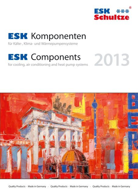
<strong>ESK</strong> Komponenten<br />
für Kälte-, Klima- und Wärmepumpensysteme<br />
<strong>ESK</strong> Components<br />
for cooling, air conditioning and heat pump systems<br />
<strong>2013</strong><br />
Quality Products · Made in Germany · Quality Products · Made in Germany · Quality Products · Made in Germany
Das Titelbild wurde von Frank Wagner gemalt.<br />
The cover-painting has been created by Frank Wagner.<br />
(www.wagner-art.de)
CATALOG <strong>2013</strong><br />
Contents<br />
<strong>ESK</strong> NEWS<br />
Inhaltsverzeichnis<br />
Allgemeines General<br />
Unser Unternehmen Our company 2<br />
Geschäftsfelder Business segments 3<br />
Leistungsumfang Range of activities 3<br />
Qualität Quality 4<br />
Einsatzbereiche unserer Produkte Application range 5<br />
Kältemaschinenöle Compressor oils 5<br />
Produkteigenschaften Product features 6<br />
Komponenten Components<br />
für HFKW / HFCKW for HFKW / HFCKW<br />
Technische Hinweise – Technical references –<br />
Ölreguliersysteme Oil Control Systems 7<br />
Ölabscheider Oil Separators 14<br />
Flüssigkeitsabscheider, Suction Line Accumulators,<br />
Multi-Flüssigkeitsabscheider Multi Suction Line Accumulators 20<br />
Ölsammler, Ölabscheider-Sammler Oil Reservoirs, Oil Separator Reservoirs 26<br />
Ölspiegelregulatoren Oil Level Regulators 30<br />
Adaptersätze zur Regulatormontage Adapter kits for regulator installation 36<br />
Absperrventilsatz, Rückschlag- Shut off valve set,<br />
und Druckdifferenzventile Check and pressure valves 37<br />
Filter Strainer 38<br />
Geräuschdämpfer Discharge Line Mufflers 39<br />
Flüssigkeitssammler Liquid Receivers 42<br />
Füllstandskontrollen Level Control 44<br />
Anwendungen mit R 410A Applications with R410A 48<br />
Komponenten für Components for<br />
natürliche Kältemittel natural refrigerants<br />
CO2-Anwendungen – Technische Hinweise CO2 applications – Technical references 50<br />
Komponenten für Betriebsdrücke von 45 bar (-CD) Components for working pressures of 45 bar (-CD) 52<br />
Komponenten für Betriebsdrücke von 60 bar (-CDM) Components for working pressures of 60 bar (-CDM) 56<br />
Komponenten für Betriebsdrücke von 130 bar (-CDH) Components for working pressures of 130 bar (-CDH) 60<br />
Anwendungen mit Ammoniak und Propan Applications with ammonia and propane 64<br />
Zubehör Accessories<br />
und Ersatzteile and Spare parts<br />
Die Angaben dieser Broschüre entsprechen dem heutigen Stand unserer<br />
Technik. Eine rechtliche Verbindlichkeit kann aus den Angaben nicht<br />
abgeleitet werden.<br />
Der Nachdruck – auch auszugsweise – ist nur mit unserer Genehmigung<br />
erlaubt. Änderungen, die dem technischen Fortschritt dienen, behalten<br />
wir uns auch ohne Ankündigung vor.<br />
MADE IN GERMANY<br />
Sonderadapter Special Adapters 66<br />
Heizelemente / Heizbänder Heater elements / Heater bands 67<br />
Rota-Ventile und Fittings Rotalock Valves and Fittings 67<br />
Schweißstutzen und -adapter Weld-solder Connectors and Adapters 68<br />
Schaugläser Sight Glasses 69<br />
Schwimmer-Flanschplatte Flange plate with float valve 70<br />
Filterpatronen Replacement elements 70<br />
Dichtungen und O-Ringe Gaskets and O-Rings 71<br />
<strong>ESK</strong>-Partner weltweit <strong>ESK</strong>-Partners worldwide 72<br />
The information given in this <strong>catalog</strong>ue is based upon our present technology.<br />
A legaly liability cannot be derived from the technical specifications.<br />
Reprints are only allowed with our permission. <strong>ESK</strong> reserves the right to<br />
change technical specifications without prior notice, especially in the interest<br />
of product improvements.<br />
� www.esk-schultze.de CATALOG 2012/13<br />
1
www.esk-schultze.de<br />
Unser Unternehmen | 1960 als Handelsunternehmen gegründet,<br />
fertigt die <strong>ESK</strong> <strong>Schultze</strong> GmbH & Co.KG seit 1984 Komponenten für die<br />
Kälte-, Klima- und Wärmepumpenbranche. Mit der langjährigen Erfahrung<br />
werden unter dem Markennamen »<strong>ESK</strong>« hochwertige Produkte entwickelt<br />
und hergestellt. 1998 wurde das Unternehmen in ein modernes<br />
Verwaltungs- und Fertigungsgebäude nach Velten (Berlin) verlagert. Eine<br />
kontinuierliche positive Entwicklung im Geschäftsverlauf kennzeichnet die<br />
weiteren Jahren.<br />
Eine umfassende, serviceorientierte Betreuung unserer Kunden von technischer<br />
Klärung und Systemberatung bis hin zur Disposition und Lieferung<br />
sind dabei unser Anspruch. Technische Kompetenz, Qualität von Prozessen<br />
und Produkten, Zuverlässigkeit, Kundenorientierung und hohe Mitarbeiterzufriedenheit<br />
sind feste Bestandteile unserer Unternehmensphilosophie.<br />
2<br />
Our company | Founded as a commercial enterprise in 1960, <strong>ESK</strong><br />
<strong>Schultze</strong> GmbH & Co.KG has manufactured components for the refrigeration,<br />
air-conditioning and heat pump industry since 1984. With this<br />
long-standing experience, today high-quality products are developed<br />
and produced under the brand name <strong>ESK</strong>. The company was shifted into<br />
a modern administration and production building in Velten (near Berlin)<br />
in 1998. The further years are characterized by a continuously positive<br />
development in business trend.<br />
Our standard is extensive, service-driven support to our customers, from<br />
technical clarification and system consultancy to arrangement and delivery.<br />
Technical competence, quality of processes and products, soundness, customer<br />
focus, as well as high staff satisfaction are vital parts of our business<br />
philosophy.<br />
CATALOG 2012/13 � www.esk-schultze.de
Geschäftsfelder | In erster Linie bedienen wir im Hause <strong>ESK</strong> zwei unterschiedliche<br />
Geschäftsfelder:<br />
1. Über unsere meist sehr langjährigen Handelspartner in aller Welt sind<br />
unsere Standardprodukte in über 40 Ländern verfügbar. Diese umfassen<br />
eine breite Palette und sind im folgenden Katalog technisch detailliert<br />
dokumentiert. Unser Produkt-Portfolio wird permanent nach den Hauptkriterien<br />
Marktnachfrage und neuesten technischen Entwicklungen<br />
aktualisiert.<br />
2. In den letzten Jahren wurde ein beträchtliches Erstausrüster(OEM)-<br />
Geschäft aufgebaut. Hier lassen sich die traditionellen <strong>ESK</strong>-Qualitäten<br />
wie Liefertreue, sinnvolle Lagerkonzepte, hohe Materialqualität und<br />
breite Produktpalette optimal mit der hohen Beratungskompetenz im<br />
Hause sowie der ausgeprägten Kundenorientierung verbinden.<br />
Diverse fein abgestimmte Fertigungs- und Materialmöglichkeiten ermöglichen<br />
in diesen Marktsegmenten Druckbehälter, Abscheider und Regulatoren<br />
von ca. 0,3–70 l und unterschiedlichsten Drucklagen bis zu 130 bar.<br />
Fragen Sie uns an !<br />
Leistungsumfang | Unser volles Leistungsspektrum sehen wir allerdings<br />
nicht ausschließlich im Produktionsbereich, sondern insbesondere<br />
auch in unserer allgemeinen technisch hohen Kompetenz von Entwicklung<br />
und Vertrieb. Dort bieten wir neben einer gezielten bedarfsabgestimmten<br />
Angebotslegung auch ganzer abgestimmter Ölmanagementsysteme<br />
zudem auch eine harmonisierte Schnittstellenanbindung an Ihre<br />
Abläufe in Produktentwicklung und Einkauf an. Die bei <strong>ESK</strong> übliche hohe<br />
und schnelle Verfügbarkeit im Standardprogramm wird mit der Möglichkeit<br />
individuell abgestimmter Lieferprozesse z. B. innerhalb von Rahmenaufträgen<br />
ergänzt. Der Export in über 40 Länder und in alle Kontinente der<br />
Welt verdeutlicht unsere Wettbewerbsfähigkeit und hohe Flexibilität.<br />
MADE IN GERMANY<br />
Business segments | <strong>ESK</strong> primarily serves two different business<br />
segments:<br />
1. Our standard products are available in more than 40 countries by<br />
mostly long-time trading partners. This wide range of products is<br />
documented technically detailed in the following <strong>catalog</strong>. Our<br />
portfolio is constantly updated regarding the main criteria market<br />
demand and latest technical developments.<br />
2. Over the past years, a substantial original equipment manufacturer<br />
(OEM) business has been established, allowing us to optimally internally<br />
combine traditional <strong>ESK</strong> qualities such as delivery reliability, expedient<br />
storage concepts, high quality of material, and a wide range of products<br />
with excellent advisory skills and distinct costumer focus.<br />
Various carefully coordinated production and material facilities allow for<br />
pressure vessels, separators and regulators of approx. 0.3–70 liters and<br />
diverse pressure partings up to 130 bar in those market segments. Contact<br />
us for further information!<br />
Range of activities | We do not, however, exclusively consider our<br />
full range of services within the production line but especially also in our<br />
overall technical high expertise regarding development and sales. There,<br />
in addition to a specific demand-coordinated proposal submission of even<br />
entire oil management systems, we also offer a harmonized interface connection<br />
to your product development and buying processes.<br />
<strong>ESK</strong>’s traditional high and fast availability regarding the standard program<br />
is supplemented with the facility of individually matched delivery<br />
processes within e.g. frame orders. The fact that we export to more than<br />
40 countries and to all continents illustrates our competitiveness as well<br />
as our high flexibility.<br />
� www.esk-schultze.de CATALOG 2012/13<br />
3
www.esk-schultze.de<br />
Qualität | Alle Geräte werden in Eigenfertigung „Made in Germany“<br />
unweit von Berlin produziert. Alle zugelieferten Bauteile werden aus europäischen<br />
Ländern bezogen. Bei unserem Kernprozess, dem Schweißen,<br />
kommen ausschließlich hochwertige Schweißverfahren und -apparaturen<br />
zum Einsatz. Bei unseren Mitarbeitern handelt es sich um Fachkräfte mit<br />
nachgewiesener Schweißausbildung. Diese unterliegen alle zwei Jahre<br />
einer eingehenden Qualifikationsprüfung.<br />
Eine weitere kurze Übersicht über Qualitätsmerkmale von <strong>ESK</strong>-Produkten:<br />
� 100 %ige Druckprüfung aller Komponenten<br />
� Zertifizierung durch den TÜV Rheinland<br />
� Zertifizierung nach AD2000-Regelwerk HP-0,<br />
• HP100R und DIN ISO 3834-2<br />
� Fertigung nach europäischer Druckgeräterichtlinie (DGRL)<br />
� Diverse landesspezifische Zulassungen (zum Beispiel CCC)<br />
Typische Merkmale unserer Produkte sind neben der hochwertigen<br />
Schweißausführung und der eingesetzten Pulverlackierung, der hohe<br />
Spezialisierungsgrad und damit die große Palette unserer Produkte, die<br />
Kompatibilität unserer Komponenten zu ganzen Ölmanagementsystemen<br />
sowie der neueste technische Stand unserer Bautypen.<br />
4<br />
Quality | We produce all devices nearby Berlin as in-house production<br />
‘Made in Germany’. All supplied elements are purchased from European<br />
countries. We exclusively apply high-class welding methods and equipment<br />
to our core process, the welding. This process is solely carried out by skilled<br />
labor with certified welding operator training. All two years special qualification<br />
tests have to be absolved.<br />
A further brief overview of quality features of <strong>ESK</strong> products:<br />
� 100 % high-pressure test of all components<br />
� Certified by TÜV Rheinland<br />
� Certification in accordance to AD2000 regulation HP-0,<br />
• HP100R and DIN ISO 3834-2<br />
� Production according to European pressure equipment guideline (DGRL)<br />
� Various country-specific approvals (e.g. CCC)<br />
Typical features of our products include first-class execution of the weld<br />
and the powder coating, the high-quality degree of specialization and<br />
therewith our wide range of products, our components’ compatibility<br />
to entire oil management systems, as well as our technically up-to-date<br />
construction types.<br />
CATALOG 2012/13 � www.esk-schultze.de
Anwendungsbereiche | <strong>ESK</strong> bietet eine Vielzahl von Standardkomponenten<br />
für die unterschiedlichsten Anwendungen an. Darüber<br />
hinaus sind im Seriengeschäft angepasste, modifizierte Produkte sowie<br />
Sonderlösungen jederzeit möglich. Bei Bedarf fragen Sie uns bitte an.<br />
Kältemaschinenöle | Die verdichterseitig verwendeten Kältemaschinenöle<br />
(Mineralöle, halbsynthetische und synthetische Öle) der Viskositätsklasse<br />
32 cSt bei 40° C sind für die verschiedenen Komponenten freigegeben.<br />
Kommt ein hochviskoses Öl, zum Beispiel der Klasse 68 oder 100cSt,<br />
zur Anwendung, ist eine Funktionsprüfung von Ölspiegelregulatoren, Ölabscheidern<br />
und Flüssigkeitsabscheidern vom Anwender durchzuführen.<br />
Der Katalog ist in mehrere Segmente aufgebaut:<br />
Blau: Komponenten für den Einsatz von<br />
HFKW- und HFCKW-Kältemitteln<br />
Grün: Komponenten für den Einsatz von CO2<br />
und Kältemitteln der Fluidgruppe 1 (NH3, Propan)<br />
Orange: Ersatzteile und Zubehör<br />
Application range | <strong>ESK</strong> offers a variety of standard components for<br />
the most diverse applications. Furthermore, we always offer facilities for<br />
products and special solutions adjusted and/or modified in line with our<br />
mass production. Please contact us as needed.<br />
Compressor oils | The normal compressor ref.-oil-charge consists of<br />
either mineral-, semi-synthetic- or synthetic-oils of viscosity class 32 cSt at<br />
40° C temperature. Our components are released for such oils. In case of an<br />
high viscose oil in application, e.g. class 68cSt or 100cSt, a functional test<br />
of oil level regulators, oil separators and suction line accumulators by the<br />
user is necessary.<br />
The <strong>catalog</strong> is arranged into several segments:<br />
Blue: Components for the use of<br />
HFC and HCFC refrigerants<br />
Green: Components for the use of CO2, and<br />
refrigerants of fluid group 1 (ammonia, propane)<br />
Orange: Spare parts and accessory<br />
MADE IN GERMANY<br />
� www.esk-schultze.de CATALOG 2012/13<br />
5
Produkt-Eigenschaften<br />
� Hohe Effizienz<br />
� Hohe Sicherheit<br />
� Lange Lebensdauer<br />
� Einfache Montage<br />
� Hervorragende Fertigungsqualität<br />
� Herstellung aller <strong>ESK</strong>-Komponenten in Deutschland<br />
� Schwimmerbauteile, Prallbleche und Siebkörper aus Edelstahl<br />
� Oberflächenschutz durch Epoxid-Einbrennlackierung RAL 5009<br />
Product features<br />
� High efficiency<br />
� Excellent reliability<br />
� Outstanding durability<br />
� Easy installation<br />
� Exceptional manufacturing quality<br />
� All <strong>ESK</strong> components are manufactured in Germany<br />
� Stainless steel float-valve components, baffles and strainer elements<br />
� Surface protection by epoxy coating, RAL 5009
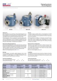
Technische Hinweise – Ölreguliersysteme<br />
Technical references – Oil Control Systems<br />
Allgemeines<br />
Verdichter-Verbundschaltungen sind durch die Anwendung mehrerer Verdichter<br />
in einem Kältekreislauf gekennzeichnet. Der Verbundbetrieb bietet<br />
für den Betreiber folgende Vorteile:<br />
� Große Kälteleistungsbereiche können mit wenigen<br />
Verdichtermodellen abgedeckt werden.<br />
� Ideale Leistungsregelung durch das Abschalten<br />
von Verdichtern bei hoher Leistungszahl.<br />
� Energieeinsparung<br />
� Ausreichende Kühlleistung bei Ausfall eines Verdichters<br />
� Unkomplizierte Anlaufstrombegrenzung<br />
� Platzsparende Anlagenkonzeption<br />
� Standardisierte Serienfertigung ermöglicht eine optimale<br />
Auswahl der Komponenten und deren Montage<br />
Öl in Verbundsystemen<br />
Die vom einzelnen Verdichter in das System geförderte Ölmenge (Ölwurf)<br />
muss dem jeweiligen Verdichter bei allen möglichen Betriebsbedingungen<br />
in gleicher Menge wieder zugeführt werden. Teillastbetrieb, lange Leitungswege,<br />
hohe Kältemittelmengen und geringfügige Herstellungstoleranzen<br />
der Verdichter erfordern die Regelung des Ölstandes im Kurbelgehäuse.<br />
Ölstand-Reguliersysteme übernehmen diese Regelung und arbeiten problemlos<br />
in der täglichen Praxis. Komplexe Verrohrungen ohne Regelfunktion<br />
sind nicht mehr erforderlich.<br />
Als zuverlässige technische Lösung haben sich Ölreguliersysteme in der<br />
Praxis bewährt. <strong>ESK</strong>-Ölreguliersysteme ermöglichen die Vorteile des Verbundbetriebes<br />
bei höchstmöglicher Anlagensicherheit zu nutzen. Beim<br />
Verbund verschiedener Verdichtermodelle, zweistufiger Verdichter und<br />
Anlagen mit sogenannten Satelliten Verdichtern ist die Überwachung und<br />
Regelung der Ölstände in den Verdichtern über ein Reguliersystem unerlässlich.<br />
In den letzten Jahren wurden neben der klassischen Ausführung<br />
der Ölreguliersysteme mit einem Niederdruck-Ölreservoir auch Systeme<br />
mit Hochdruck-Reservoir eingesetzt.<br />
Steigerung der Energieeffizienz durch Ölreguliersysteme<br />
Der Verbundanlagenbau kann aufgrund allgemeiner Empfehlungen unterschiedlich<br />
ausgeführt werden. Kostengünstige Ausführungen basieren auf<br />
idealisierten Annahmen. In realer Anwendung, wie zum Beispiel im Bereich<br />
der Supermarktkühlanlagen mit einem komplexen und langen Rohrleitungsnetz,<br />
großen Kältemittelfüllmengen und häufigem Teillastbetrieb, liegen<br />
Bedingungen vor, die sich erheblich vom Ideal unterscheiden können.<br />
Beim Einsatz eines saugseitigen Verteilers anstelle eines Ölreguliersystems<br />
spart man pro Verbundsatz 600 bis 800 € an Investitionskosten. Während<br />
der Inbetriebnahme oder im Servicefall werden zu geringe oder unterschiedliche<br />
Ölstände in den Verdichtern, bedingt durch Verdichter-Fertigungstoleranzen<br />
und Laufzeitdifferenzen, durch wiederholendes Auffüllen<br />
von Öl ausgeglichen. Nach Sättigung der Anlage mit Öl ist ein nicht effizienter<br />
Betrieb bei variierenden Betriebsbedingungen ermöglicht.<br />
Einflüsse von Kältemaschinenöl im Kältekreislauf<br />
Eine hinreichende Schmierung der Verdichter mit einem Kältemaschinenöl<br />
ist zwingend erforderlich, um Schädigungen oder Zerstörungen durch<br />
erhöhten Verschleiß der Maschinen zu vermeiden. Dabei ist es nicht zu verhindern,<br />
dass eine geringe Menge Öl, etwa 1 bis 3 Prozent des Kältemittel-<br />
Massenstroms, über den Verdichter in den Kältemittelkreislauf gelangt.<br />
Schon geringe Mengen Öl im Kältemittelmassenstrom können die Ursache<br />
für einen Anstieg des Kondensationsdruckes (pc) im Verflüssiger sein [ 1].<br />
Eine Verschlechterung des Wärmeübergangs durch Öl im Verdampfer führt<br />
zu tieferen Verdampfungstemperaturen, was einen geringeren Druck auf<br />
der Saugseite (Verdampfungsdruck p0) des Kältekreislaufs bedeutet. Das<br />
erhöhte Verhältnis von pc / p0 führt zu einer Reduzierung des Verdichter-<br />
Liefergrades, was bei geringerer Kälteleistung verlängerte Laufzeiten der<br />
Kältemittelverdichter zur Folge hat [ 2].<br />
General<br />
Modern refrigeration plants often utilizes two or more compressors in parallel.<br />
This offers many advantages to the user, including:<br />
� Vast capacity ranges can be covered<br />
by few compressor models<br />
� Optimal capacity control and capability<br />
for high energy efficiency<br />
� Energy saving<br />
� Back-up capacity in the event of one compressor failing<br />
� Comparatively easy starting characteristics<br />
� Space saving, compact construction<br />
� Serial production, enables an optimal selection<br />
of components and their installation.<br />
MADE IN GERMANY<br />
Oil in Parallel Compressor Systems<br />
The oil quantity carried over by an individual compressor in parallel systems<br />
must be returned in the same quantity under all operating conditions.<br />
Part load, long piping, high refrigerant charge and manufacturer tolerances<br />
of compressors makes the control of crankcase oil level necessary.<br />
Oil control systems provides this control and works reliable.<br />
It makes complex piping and valving unnecessary.<br />
<strong>ESK</strong> oil systems make it possible to utilize the advantages of parallel compressor<br />
plant to the maximum whilst maintaining the safety and reliability<br />
requirement.<br />
Oil control systems are essential to control and watch oil levels if different<br />
compressor models, two-stage compressors and so called systems with satellite<br />
compressors are involved. In the past years, beside the classic design<br />
of oil system with low pressure oil reservoir, systems with high pressure oil<br />
reservoirs are used.<br />
Energy efficiency increase by using Oil control systems<br />
The construction of multiple compressor racks can be executed variably due<br />
to general recommendations. Low cost solutions are based on idealized<br />
assumptions. In real applications, such as in the supermarket area with a<br />
complex and long distance piping network, large refrigerant charges and<br />
frequent part-load conditions are conditions which considerably differ from<br />
the ideal.<br />
Systems with a suction header instead of an oil control system save, on the<br />
average, approx. 600 – 800 € per pack on investment. During commissioning<br />
of the system or when servicing, too low oil levels in the compressor<br />
crankcases are compensated by repeatingly charging additional oil. The<br />
different oil levels are a result of compressor tolerances as well as various<br />
operating conditions. After a system saturation with oil, a non-efficient<br />
operation is possible at various conditions.<br />
Influence of oil in the refrigeration cycle<br />
An adequate lubrication of the compressor with an refrigerating oil is<br />
obligatory to avoid damages by wear of bearings, pistons, connecting rods<br />
and crankshaft. Thereby, ref.-compressors unavoidably have an oil carry<br />
over rate of approx. 1–3 % of refrigeration mass flow.<br />
Small amounts of oil can already be the reason for an increase of the condensing<br />
pressure (pc). A deterioration of the heat transfer in the evaporator<br />
caused by oil will lead to lower evaporating pressure (p0).<br />
The rise of the pressure ratio pc/p0 has a negative impact on the volumetric<br />
efficiency. The system operation time increases in respect of the<br />
compressorcapacity reduction.<br />
� www.esk-schultze.de CATALOG 2012/13<br />
7<br />
<strong>ESK</strong> COMPONENTS FOR<br />
HFKW / HFCKW NATURAL REFRIGERANTS ACCESSORIES
<strong>ESK</strong> COMPONENTS FOR HFKW / HFCKW NATURAL REFRIGERANTS ACCESSORIES<br />
www.esk-schultze.de<br />
Anwendung von Ölreguliersystemen<br />
Durch den Einsatz eines Ölreguliersystems, bestehend aus Ölabscheider,<br />
Ölsammler und Ölspiegelregulator werden eine Reihe von positiven<br />
Eigenschaften hinsichtlich Zuverlässigkeit und Energieeinsparung erreicht.<br />
Durch den Einsatz eines Ölabscheiders kann das in den Kältemittel-Massenstrom<br />
gelangte Öl fast vollständig abgeschieden werden. Dadurch steigt<br />
der COP der Anlage. Weiterhin wird eine geringere Verdichterlaufzeit erreicht,<br />
was den Energieverbrauch der Anlage und die indirekte CO2-<br />
Emission reduziert.<br />
Das Ölsammelgefäß erfüllt wichtige Funktionen hinsichtlich der Verbesserung<br />
der Eigenschaften des Kältemaschinenöls vor der „Wiederverwendung“.<br />
Über ein Druckdifferenzventil wird ein Druck mit D p =1,5 bar über Saugdruck<br />
eingestellt. Durch den Druckabfall von Kondensationsdruck zum Sammlerdruck<br />
entmischt sich im Öl gelöstes Kältemittel und entweicht zur Saugseite. Weiterhin<br />
kann das heiße abgeschiedene Öl im Sammler abkühlen. Die Entmischung<br />
und die Abkühlung wirken sich positiv auf Schmiereigenschaften des Öls<br />
aus. In Verbindung mit den Ölspiegelregulatoren wird die Versorgung<br />
mit Öl und die optimale Regelung des Ölstandes auf Mitte Schauglas der<br />
Verdichter gesichert. Durch den Einsatz von Ölreguliersystemen können<br />
somit Werte geschützt und zusätzliche Kosten vermieden werden.<br />
Kostenrechnung an einem Supermarkt-Beispiel<br />
Steigt der Energiebedarf durch das „Verölen” der Anlagen nur um zwei Prozent,<br />
haben sich die Ölreguliersysteme bereits nach einem Jahr amortisiert.<br />
<strong>ESK</strong>-Ölreguliersystem mit Niederdruck Ölreservoir<br />
Das System setzt sich aus folgenden <strong>ESK</strong>-Komponenten zusammen:<br />
� <strong>ESK</strong>-Ölabscheider � <strong>ESK</strong>-Druckdifferenzventil<br />
� <strong>ESK</strong>-Ölsammler � <strong>ESK</strong>-Filter<br />
� <strong>ESK</strong>-Ölspiegelregulatoren � <strong>ESK</strong>-Flüssigkeits- bzw. Multiabscheider<br />
<strong>ESK</strong>-Ölreguliersystem mit Hochdruck Ölreservoir<br />
Das System setzt sich aus folgenden <strong>ESK</strong>-Komponenten zusammen:<br />
� <strong>ESK</strong>- Ölabscheider-Sammler<br />
� <strong>ESK</strong>- Ölspiegelregulatoren, elektronisch<br />
� <strong>ESK</strong>- Filter<br />
� <strong>ESK</strong>- Flüssigkeits- bzw. Multiabscheider<br />
Bei Hochdrucksystemen wird Öl mit hoher Temperatur und einer erheblichen<br />
Entmischung (Schaumbildung) über einen elektronischen Regulator<br />
zugeführt. Mechanische Regulatoren sind für Anwendungen mit Druckdifferenzen<br />
> 6 bar nicht mehr einsetzbar.<br />
Bei Niederdrucksystemen wird das Öl im Ölsammler abgekühlt, entspannt<br />
und entgast. Ein Regulator, mechanisch oder elektronisch, führt dem Verdichter<br />
Öl ohne weitere Entmischung zu. Die Anordnung der Komponenten<br />
und deren Auslegung werden im folgenden beschrieben.<br />
Application of oil control systems<br />
By installing an oil control system, consisting of an oil separator, oil reservoir,<br />
oil level regulators, strainers and pressure valve, a number of positive<br />
features are achieved regarding reliability and energy savings.<br />
The oil separator reduces the amount of oil flowing through the system<br />
almost completely. That improves the COP of the system, reduces compressor<br />
operating time and saves energy. The indirect CO2 emissions are<br />
reduced.<br />
The oil reservoir fulfills important functions with respect quality of the before<br />
the reintroduction into the compressor. By the application of a pressure valve<br />
a pressure of 1,5 bar above suction pressure is maintained in the oil reservoir.<br />
Due to the pressure drop from condensing pressure to reservoir pressure,<br />
refrigerant trapped within the oil will escape into the suction line.<br />
Furthermore the oil will cool down in the reservoir. The reduction of the<br />
refrigerant concentration and the cool down improve the lubrication qualities<br />
of the oil. In connection with the oil level regulators, the supply with<br />
oil as well as an optimal control of the oil level in the compressor crankcase<br />
at center sight glass level is achieved.<br />
Compressors are one of the most cost-intensive components in an industrial<br />
refrigeration system. A failed compressor is associated with considerable<br />
costs arising from replacements or servicing of existing plants. By<br />
applying an OCS, compressor lubrication failures can be mostly avoided.<br />
Calculation of costs of a supermarket installation<br />
Supermarkt Normalkühlung Supermarkt Tiefkühlung<br />
Supermarket medium temperature Supermarket low temperature<br />
Verdichter Anzahl Number of compressors 4 4<br />
Kältemittel Refrigerant R404A R404A<br />
Betriebsbedingungen Operating conditons to = –10°C tc = 40°C to = –35°C tc = 40°C<br />
Leistungsdaten / Verdichter Capacity data / compressor Qo = 27 kW Pel = 11 kW Qo = 8 kW Pel = 6 kW<br />
Laufzeit / Jahr Operation time / year 6000 h 6000 h<br />
Stromverbrauch / Jahr Energy consumtion / year 6000 h x 44 kW = 264.000 kWh 6000 h x 24 kW = 144.000 kWh<br />
Energiekosten / Jahr Energy cost / year K = 264.000 kWh x 0,16 EUR/kWh K = 144.000 kWh x 0,16 EUR/kWh<br />
K = 42.240 EUR K = 23.040 EUR<br />
If the energy demand increases only by 2 % due to a higher oil saturation<br />
of a system, the OCS has already amortized itself after the first year.<br />
Quellenangaben / References<br />
[ 1] Lebreton, Jean-Marc; Vuillame, Louis „Oil Concentration Measurement in Saturated [ 2] „Anhaltende Einsparungen bei Kälteanlagen“ SPEKTRUM der Gebäudetechnik 4/2001<br />
Refrigerant Flowing Inside a Refrigeration Machine“ In. J. Applied Thermodynamics, Vol.4, (No.1)<br />
8<br />
Technische Hinweise – Ölreguliersysteme<br />
Technical references – Oil Control Systems<br />
<strong>ESK</strong>-Oil Control System with Low Pressure Reservoir<br />
The system consists of the following <strong>ESK</strong>-components:<br />
� <strong>ESK</strong>-Oil Separators � <strong>ESK</strong>-Pressure Valve<br />
� <strong>ESK</strong>-Reservoir � <strong>ESK</strong>-Strainers<br />
� <strong>ESK</strong>-Oil Level regulators � <strong>ESK</strong>-Suction line- and multi accumulators<br />
<strong>ESK</strong>-Oil Control System with High Pressure Reservoir<br />
The system consist of the following components:<br />
� <strong>ESK</strong>- Oil Separator-Reservoir<br />
� <strong>ESK</strong>- Oil Level Regulator, electronic<br />
� <strong>ESK</strong>- Strainer<br />
� <strong>ESK</strong>- Suction Line - and Multi accumulators<br />
In high pressure systems oil will feed into crankcase by means of an electronic<br />
regulator. Extreme reduction of ref. Concentration will lead into<br />
strong foam formation. Mechanical regulators are not applicable if pressure<br />
difference will exceed 6 bar.<br />
In low pressure systems the oil will be cooled down, refrigerant in oil will<br />
boiled off. An oil level regulator, mechanical or electronic feed the compressor<br />
without a remarkable change of ref. concentration. The combination<br />
and selection of components are described on the following pages.<br />
CATALOG 2012/13 � www.esk-schultze.de
Technische Hinweise – Ölreguliersysteme<br />
Technical references – Oil Control Systems<br />
Systemdiagramme<br />
Grundsätzlich gibt es für die Konstruktion einer Verbundanlage nach Anforderung,<br />
Betriebsbedingungen und Verdichterbauart verschiedene Lösungsmöglichkeiten.<br />
Im Folgenden werden allgemein gültige Schaltdiagramme<br />
aufgezeigt, die im Einzelnen verändert oder kombiniert werden können:<br />
Systemdiagramm: ORS 1 mit Niederdruck Ölreservoir<br />
Mehrere Ölabscheider (7) führen das Öl aus dem Druckgasstrom zum<br />
Ölsammelgefäß (2). Bei der Parallelschaltung von Ölabscheidern ist darauf<br />
zu achten, dass ein Rückschlagventil RV-10B/0,1 (3) auf dem Ölabscheider<br />
aufgeschraubt bzw. in der Ölrückführleitung eingebaut wird. Parallel<br />
geschaltete Ölabscheider öffnen und schließen nicht im Takt, die Rückschlagventile<br />
verhindern somit das Rückfluten von Öl in den nicht „geöffneten“<br />
Abscheider. <strong>ESK</strong>-Ölabscheider sind auf den Seiten 14 ff ausführlich<br />
beschrieben.<br />
Das Öl wird im Ölsammler (2) über das Druckdifferenzventil RV2-10B/1,5 (1)<br />
entspannt und über einen Regulator (5) mit vorgeschaltetem Filter (4) dem<br />
Verdichter zugeführt.<br />
ORS 1<br />
1 Druckdifferenzventil RV2-10B/1.5<br />
2 Ölsammelgefäß OSA<br />
3 Rückschlagventil RV-10B/0.1<br />
4 Ölfilter F-10B / F-10L<br />
5 Ölspiegelregulator OR…, ERM2 etc.<br />
6 Flüssigkeitsabscheider FA..<br />
7 Ölabscheider OS / BOS2<br />
8 Verdichter<br />
9 Rückschlagventil RV<br />
System Diagrams<br />
1 Pressure valve RV2-10B/1.5<br />
2 Oilreservoir OSA<br />
3 Check valve RV-10B/0.1<br />
4 Strainer F-10B / F-10L<br />
5 Oil level regulator OR…, ERM2 etc.<br />
6 Suction line accumulator FA..<br />
7 Oil separator OS / BOS2<br />
8 Compressor<br />
9 Check valve RV<br />
MADE IN GERMANY<br />
Based on specification, operating conditions, compressor version, etc.<br />
there are different possibilities to design a parallel system. On the following<br />
pages, we are showing general system diagrams which could be modified<br />
or combined:<br />
System diagram: ORS 1 with low pressure Oil reservoir<br />
Several Oil separators (7) are used to separate the oil from the compressor<br />
discharge gas and return this oil to the oil reservoir (2). When<br />
more than one separator is used, it is essential to fit a RV-10B/0,1 (3)<br />
check valve at the oil separator outlet in the return line from each oil<br />
separator. This will ensure that oil cannot flow from one separator to the<br />
other as the float valves do not open and close together.<br />
<strong>ESK</strong> oil separators are described in detail on pages 14 ff.<br />
In the oil reservoir (2) the oil is decompressed by the pressure valve<br />
RV2-10B/1,5 (1) and returned to the compressor via an oil level regulator (5).<br />
In front of the regulator a strainer (4) should be installed.<br />
� www.esk-schultze.de CATALOG 2012/13<br />
©<br />
9<br />
<strong>ESK</strong> COMPONENTS FOR<br />
HFKW / HFCKW NATURAL REFRIGERANTS ACCESSORIES
<strong>ESK</strong> COMPONENTS FOR HFKW / HFCKW NATURAL REFRIGERANTS ACCESSORIES<br />
www.esk-schultze.de<br />
Systemdiagramm: ORS2 mit Niederdruck Ölreservoir<br />
Ein zentraler Ölabscheider (7) scheidet das Öl aus dem Druckgasstrom ab.<br />
Dieses System ist in der Praxis am häufigsten anzutreffen. Der Ölabscheider<br />
ist für die Gesamtleistung der Anlage auszulegen. Der Arbeitsprozess entspricht<br />
dem unter ORS 1 beschriebenen.<br />
Anwendung von Flüssigkeitsabscheidern<br />
und Multiabscheidern in Verbundsystemen<br />
Verdichter in Verbundschaltung sind bei entsprechenden Einsatzbedingungen<br />
mit einem Flüssigkeitsabscheider auszurüsten. Für den Verbund<br />
von bis zu vier Verdichtern stehen serienmäßig gefertigte Multi-Flüssigkeitsabscheider<br />
zur Verfügung. Die Abscheider sind ausführlich auf den<br />
Seiten 20 bis 25 beschrieben.<br />
10<br />
ORS 2<br />
1 Druckdifferenzventil RV2-10B/1.5<br />
2 Ölsammelgefäß OSA<br />
4 Ölfilter F-10B / F-10L<br />
5 Ölspiegelregulator OR…, ERM2 etc.<br />
6 Flüssigkeitsabscheider FA..<br />
7 Ölabscheider OS / BOS2<br />
8 Verdichter<br />
9 Rückschlagventil RV<br />
Technische Hinweise – Ölreguliersysteme<br />
Technical references – Oil Control Systems<br />
System diagram: ORS2 with low pressure Oil reservoir<br />
One central oil separator (7) separates the oil from the compressor discharge<br />
gas. This is the system installed most frequent in practice. The oil<br />
separator is to select according to the total performance of the system. The<br />
working process is same as described for ORS 1.<br />
Application of suction line accumulators and<br />
multi-accumulators for parallel systems<br />
Compressors in parallel operation have to be protected by a suction line accumulator<br />
depending on application conditions. For the parallel operation of<br />
up to 4 compressors standard multi-accumulators are available.<br />
The accumulators are described in detail on pages 20 to 25.<br />
1 Pressure valve RV2-10B/1.5<br />
2 Oilreservoir OSA<br />
4 Strainer F-10B / F-10L<br />
5 Oil level regulator OR…, ERM2 etc.<br />
6 Suction line accumulator FA..<br />
7 Oil separator OS / BOS2<br />
8 Compressor<br />
9 Check valve RV<br />
CATALOG 2012/13 � www.esk-schultze.de<br />
©
Technische Hinweise – Ölreguliersysteme<br />
Technical references – Oil Control Systems<br />
Systemdiagramm: ORS 3 mit Niederdruck Ölreservoir<br />
Verdichter, zweistufig, ein Ölabscheider je Verdichter<br />
Bei zweistufigen Verdichtern steht das Kurbelgehäuse unter Mitteldruck.<br />
Um das Öl vom Ölsammelgefäß dem Verdichter-Kurbelgehäuse zuführen<br />
zu können, muss die Druckausgleichsleitung DAL am Zwischendruck angeschlossen<br />
werden. Bedingt durch die Zwischenstufen-Nacheinspritzung<br />
unterliegt der Mitteldruck Schwankungen von +/– 0,5 bar.<br />
Manche Verdichterhersteller empfehlen deshalb für den Teillastbetrieb ein<br />
Magnetventil (10) in die DAL zum Einzelverdichter einzubauen. Bei Stillstand<br />
des Verdichters ist das Ventil geschlossen.<br />
Aus Gründen der Übersichtlichkeit wurde auf die Darstellung der<br />
Zwischenstufeneinspritzung verzichtet.<br />
ORS 3<br />
1 Druckdifferenzventil RV2-10B-1.5<br />
2 Ölsammelbehälter OSA<br />
3 Rückschlagventil RV-10B-0.1<br />
4 Ölfilter F-10B / F-10L<br />
5 Ölspiegelregulator OR…, ERM2 etc.<br />
6 Flüssigkeitsabscheider FA../FA..W<br />
7 Ölabscheider OS / BOS2<br />
8 Verdichter; zweistufig<br />
9 Rückschlagventil RV<br />
10 Magnetventil<br />
11 Flüssigkeitsleitung<br />
1 Pressure valve RV2-10B-1.5<br />
2 Oilreservoir OSA<br />
3 Check valve RV-10B-0.1<br />
4 Strainer F-10B / F-10L<br />
5 Oil level regulator OR…, ERM2 etc.<br />
6 Suction line accumulator FA../FA..W<br />
7 Oil separator OS / BOS2<br />
8 Compressor, two stage<br />
9 Check valve<br />
10 Solenoid valve<br />
11 Liquid line<br />
MADE IN GERMANY<br />
System Diagram: ORS 3 with low pressure Oil reservoir<br />
Compressor, tw o stage, one oil separator per compressor<br />
The crankcase of two stage compressors keeps normally the INTERSTAGE<br />
pressure. To get the oil from the oil reservoir into the compressor crankcase<br />
the pressure equalization line DAL has to be connected to the interstage<br />
pressure. Depending on the interstage liquid injection the interstage<br />
pressure may vary +/–0.5 bar. Therefore, compressor manufactures some-<br />
times advice to install a solenoid valve (10) into DAL to each compressor.<br />
During compressor stand still periods the valve is closed.<br />
Interstage liquid injections are not shown in the system diagram.<br />
� www.esk-schultze.de CATALOG 2012/13<br />
©<br />
11<br />
<strong>ESK</strong> COMPONENTS FOR<br />
HFKW / HFCKW NATURAL REFRIGERANTS ACCESSORIES
<strong>ESK</strong> COMPONENTS FOR HFKW / HFCKW NATURAL REFRIGERANTS ACCESSORIES<br />
www.esk-schultze.de<br />
Systemdiagramm: ORS 4 mit Niederdruck Ölreservoir<br />
Verdichter, einstufig mit unterschiedlichen Saugdrücken (Satellit)<br />
Satellitensysteme sind dadurch gekennzeichnet, dass die Verdichter eine<br />
gemeinsame Druckleitung besitzen, die Saugleitungen aber getrennt sind.<br />
Die Verdichter arbeiten bei unterschiedlichen Saugdrücken.<br />
Bei der Installation eines Ölreguliersystems für ein solches System sind folgende<br />
Hinweise zu beachten:<br />
1. Die Druckausgleichsleitung ist an die Saugleitung mit dem höchsten<br />
Betriebsdruck anzuschließen.<br />
2. Verdichter mit niedrigerem Saugdruck sind mit einstellbaren Regulatoren<br />
(bis maximal 6,5 bar Druckdifferenz zum Ölsammlerdruck) oder mit<br />
elektronischen Ölspiegelregulatoren vom Typ ERHD.. auszurüsten.<br />
12<br />
ORS 4<br />
1<br />
2<br />
4<br />
5a<br />
5b<br />
6<br />
9<br />
7<br />
SL1<br />
TO1<br />
System Diagram: ORS 4 with low pressure oil reservoir<br />
Compressors, single stage with different suction pressures<br />
For the oil management of multi compressor system, which have common<br />
discharge line, but separate suction lines with different suctions pressures,<br />
the following pints should be considered:<br />
1. The pressure equalization line is to be connected with the suction line<br />
which has the highest working pressure.<br />
2. The Compressors working with lower suction pressure are to be equipped<br />
with adjustable oil lever regulators type ORE2.. (up to a maximum pressure<br />
difference between suction and oil reservoir pressure of 6,5 bar) or<br />
with electronic oil level regulators type ERHD.. .<br />
SL2<br />
TO2<br />
1 Druckdifferenzventil RV2-10B/1.5 1 Pressure valve RV2-10B/1.5<br />
2 Ölsammelgefäß OSA 2 Oilreservoir OSA<br />
4 Ölfilter F-10B / F-10L 4 Strainer F-10B / F-10L<br />
5a Ölspiegelregulator OR...., ERM2 etc. 5a Oil level regulator OR...., ERM2 etc.<br />
5b Ölspiegelregulator ORE 2...., ERHD... 5b Oil level regulator ORE 2...., ERHD...<br />
6 Flüssigkeitsabscheider FA 6 Suction line accumulator FA...<br />
7 Ölabscheider OS / BOS2 7 Oil separator OS / BOS2<br />
8 Verdichter 8 Compressor<br />
9 Rückschlagventil RV 9 Check valve RV<br />
Technische Hinweise – Ölreguliersysteme<br />
Technical references – Oil Control Systems<br />
CATALOG 2012/13 � www.esk-schultze.de<br />
9<br />
8<br />
©
Technische Hinweise – Ölreguliersysteme<br />
Technical references – Oil Control Systems<br />
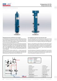
Systemdiagramm: ORS 5 mit Hochdruck-Ölreservoir<br />
Das System wird mit einer Kombination Ölabscheider-Sammler ausgerüstet.<br />
Der Ölabscheider-Sammler hat kein internes Schwimmerventil.<br />
Das Öl steht unter Verflüssigungsdruck und wird so den elektronischen<br />
Ölspiegelregulatoren direkt zugeführt. Die dafür konzipierten elektronischen<br />
Ölspiegelregulatoren vom Typ ERHD werden ausführlich auf<br />
Seite 32 beschrieben. Die anlagentechnischen Hinweise auf der Seite 8<br />
sind zu beachten. Eine Langzeiterprobung von Systemen mit Hochdruck-<br />
Ölreservoir ist durchzuführen. Mechanische Ölspiegelregulatoren sind für<br />
diese Anwendung nicht einsetzbar.<br />
ORS 5<br />
1 Ölabscheider-Sammler OSR / BOS2-R<br />
2 Ölfilter FF-16<br />
3 Ölspiegelregulator ERHD..<br />
4 Flüssigkeitsabscheider FA..<br />
5 Verdichter<br />
6 Rückschlagventil<br />
1 Oil separator-reservoir OSR / BOS2-R<br />
2 Strainer FF-16<br />
3 Oil level regulator ERHD..<br />
4 Suction line accumulator<br />
5 Compressor<br />
6 Check valve<br />
MADE IN GERMANY<br />
System Diagram: ORS 5 with high pressure Oil reservoir<br />
The system is equipped with a combination of an oil separator-reservoir.<br />
No float valve is installed into oil separator reservoir. The oil has<br />
condensing pressure and will directly feed to the electronic oil level<br />
regulators. Electronic oil level regulators of Type ERHD are approved<br />
for high pressure applications and described in detail on page 32.<br />
The technical advises on page 8 should be considered.<br />
A long-term approval of systems with high pressure oil reservoir is mandatory.<br />
Mechanical oil level regulators are not suitable for this application.<br />
� www.esk-schultze.de CATALOG 2012/13<br />
©<br />
13<br />
<strong>ESK</strong> COMPONENTS FOR<br />
HFKW / HFCKW NATURAL REFRIGERANTS ACCESSORIES
<strong>ESK</strong> COMPONENTS FOR HFKW / HFCKW NATURAL REFRIGERANTS ACCESSORIES<br />
www.esk-schultze.de<br />
Allgemeines<br />
Mit dem Kältemittel-Massenstrom wird üblicherweise ein Anteil Öl/Ölnebel<br />
vom Verdichter in die Anlage gefördert. Je nach Betriebsbedingungen<br />
kann dadurch ein Schmiermittelmangel im Verdichter mit folgenden<br />
Auswirkungen auftreten:<br />
� Niedriger Öldruck<br />
� Lagerschäden<br />
� Kolbenabrieb<br />
� Motorschaden<br />
Weiterhin wird bei einem zu hohen Ölanteil im Verdampfer der Wärmeübergang<br />
ungünstig beeinflusst und die Verdichterlaufzeit erhöht.<br />
<strong>ESK</strong>-Ölabscheider werden deshalb für die Projektierung kostengünstiger<br />
Anlagen auch von Verdichterherstellern unbedingt bei folgenden Kriterien<br />
empfohlen:<br />
� Systemen mit to
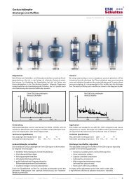
Ölabscheider<br />
Oil Separators<br />
Auswahlgrundsätze<br />
1. Die Anschlussgröße Ø DL des Ölabscheiders darf niemals kleiner<br />
gewählt werden als der Druckleitungsdurchmesser, der entsprechend<br />
kältetechnischer Regeln dimensioniert wurde.<br />
2. Die in der Tabelle den Ölabscheidern zugeordneten max. zul. theoretischen<br />
Fördervolumina der Verdichter dürfen nicht überschritten werden<br />
(VH max. theo.).<br />
3. Bei zweistufigen Verdichtern ist die Auswahl entsprechend der Volumen-<br />
Angabe bei Verdampfungstemperatur –10 °C (Tabelle) vorzunehmen:<br />
VH = (VHND + VHHD) / 2.<br />
4. Abweichende Auslegungen sind aufgrund versuchstechnischer<br />
Erprobung zulässig.<br />
Installationshinweise<br />
Bei Inbetriebnahme der Anlage ist der Ölabscheider mit der Erstölfüllung<br />
(Verdichter-Kältemaschinenöl) über den Anschlussstutzen ”IN” vorzufüllen.<br />
Standard Installation<br />
Parallel Installation<br />
1 Verdichter<br />
Compressor<br />
2 Rückschlagventil<br />
Check Valve<br />
3 Ölrückführleitung<br />
Oil Return Line<br />
4 Ventil RV-10B/0.1<br />
Valve RV-10B/0.1<br />
5 Vibrationsabsorber<br />
Vibration Eliminator<br />
2a Bei Anlaufentlastung des Verdichters muss zusätzlich ein<br />
Rückschlagventil vor dem Ölabscheider installiert werden.<br />
2a If the compressor is equipped with an unloaded start device an<br />
additional check valve must be installed in front of the oil separator.<br />
Selection<br />
1. The connection size of the oil separator should never be smaller than<br />
the discharge-line size, which has been selected according to the technical<br />
rules of refrigeration.<br />
2. The maximum theoretical displacement of the compressor shown<br />
in the table, should not be exceeded (VH max. theo.).<br />
3. The selection for two stage compressors should base on displacement<br />
at –10 °C evaporating temperature (see table):<br />
VH = (VHLP + VHHP) / 2.<br />
4. Deviations from a.m. advices are allowed if lab test shows reliable<br />
operating results.<br />
Installation<br />
Before system set up the correct quantity of the first charge oil, (compressor<br />
refrigeration oil) should be poured into the ”IN” connection at the oil<br />
separator.<br />
Auslegungsbeispiele Examples of Selection<br />
Beispiel Verdichter Verdichter-Anschluss Leistungsregelung Verdampfungstemp. <strong>ESK</strong>-Produkt<br />
Example Compressor Compressor-Connection Capacity-Control Evaporating temp. <strong>ESK</strong>-Product<br />
No. VH Ø DL Ø DL auf/to to<br />
[m³ / h] [mm] [inch] [%] [°C]<br />
1 12 16 5/8 – – 8 OS-16<br />
2 77 28 1–1/8 50 – 25 OS-28H<br />
3 142* 35 1–3/8 – – 35 OS-35H<br />
4 126 35 1–3/8 30 + 5 OS-42FY<br />
* Verdichter 2-stufig / Compressor 2 stage to = –10 °C / VH = 142 m³ / h / 2 = 71 m³ / h<br />
Montage-Position Nur vertikal, Eintritt – OBEN<br />
Mounting-Position Vertical only, In – TOP<br />
OS-Typ Erste Ölfüllung [kg]<br />
OS-Type First Oil Charge [kg]<br />
OS 10 0,4<br />
OS.. 0,6<br />
OS..F 0,6<br />
OS..FL 0,6<br />
OS..FM 0,6<br />
OS..FH..FS 0,6<br />
OS..FX, ..FY 0,6<br />
OS..H 1,2<br />
MADE IN GERMANY<br />
� www.esk-schultze.de CATALOG 2012/13<br />
15<br />
<strong>ESK</strong> COMPONENTS FOR<br />
HFKW / HFCKW NATURAL REFRIGERANTS ACCESSORIES
<strong>ESK</strong> COMPONENTS FOR HFKW / HFCKW NATURAL REFRIGERANTS ACCESSORIES<br />
www.esk-schultze.de<br />
Ölabscheider Abb. Lötanschluss Inhalt VH (m³/h) max. zul. Verdichter Hubvolumen, Abmessungen Gewicht DRL<br />
innen theo. bei 40 °C Verflüssigungstemperatur<br />
Oil Separator Draw. Solder Conn. Volume VH (m³/h) max. admissible Comp.Displacement, Dimensions Weight PED<br />
O. D. theo. at 40 °C condensing temperature<br />
Ölabscheider<br />
Oil Separators<br />
Technische Daten Technical Data<br />
Typ Ø DL Ø DL Verdampfungstemp. / Evaporating temp. °C Ø D H A Kategorie/Modul<br />
Type mm inch l (dm³) 10 0 –10 –20 –30 mm mm mm kg Category/Module<br />
Version: geschlossen / hermetic<br />
OS-10 a 10 3/8 1,2 7 8 9 10 12 108 209 60 2,0 –<br />
OS-10-12 a 12 – 2,3 10 10 11 12 14 125 262 60 2,2 I / A<br />
OS-1/2” a – 1/2 2,3 10 10 11 12 14 125 262 60 2,2 I / A<br />
OS-16 a 16 5/8 2,3 15 16 18 20 26 125 262 60 2,9 I / A<br />
OS-18 a 18 – 3,5 22 24 27 30 36 125 389 60 2,9 I / A<br />
OS-3/4” a – 3/4 3,5 22 24 27 30 36 125 389 60 3,4 I / A<br />
OS-22 a 22 7/8 3,5 25 30 35 40 50 125 392 60 3,4 I / A<br />
OS-28 a 28 1-1/8 3,5 25 30 35 40 50 125 400 60 3,4 I / A<br />
OS-35 a 35 1-3/8 3,5 25 30 35 40 50 125 407 60 3,4 I / A<br />
OS-42 a 42 1-5/8 3,5 25 30 35 40 50 125 413 60 3,4 I / A<br />
OS-22H b 22 7/8 7,5 35 42 50 60 75 200 350 100 5,6 II / A1<br />
OS-28H b 28 1-1/8 7,5 55 60 67 75 90 195 355 100 5,6 II / A1<br />
OS-35H b 35 1-3/8 7,5 60 70 80 90 110 200 360 100 6,0 II / A1<br />
OS-42H b 42 1-5/8 7,5 65 75 88 100 125 200 366 100 6,0 II / A1<br />
OS-54H b 54 2-1/8 7,5 70 80 92 105 130 200 373 100 7,0 II / A1<br />
16<br />
a b c<br />
1) Ölrückführung 10 x 1 Bördel / Oil Return 3/8“ Flare<br />
CATALOG 2012/13 � www.esk-schultze.de
Ölabscheider<br />
Oil Separators<br />
Technische Daten Technical Data<br />
Ölabscheider Abb. Lötanschluss Inhalt VH (m³/h) max. zul. Verdichter Hubvolumen, Abmessungen Gewicht DRL<br />
innen theo. bei 40 °C Verflüssigungstemperatur<br />
Oil Separator Draw. Solder Conn. Volume VH (m³/h) max. admissible Comp.Displacement, Dimensions Weight PED<br />
O. D. theo. at 40 °C condensing temperature<br />
Typ Ø DL Ø DL Verdampfungstemp. / Evaporating temp. °C Ø D H A Kategorie/Modul<br />
Type mm inch l (dm³) 10 0 –10 –20 –30 mm mm mm kg Category/Module<br />
Version: geflanscht / flanged<br />
OS-22F c 22 7/8 3,7 27 32 37 43 55 125 558 60 6,0 I / A<br />
OS-28F c 28 1-1/8 3,7 27 32 37 43 55 125 566 60 6,0 I / A<br />
OS-35F c 35 1-3/8 3,7 27 32 37 43 55 125 573 60 6,0 I / A<br />
OS-42F c 42 1-5/8 3,7 27 32 37 43 55 125 579 60 6,0 I / A<br />
OS-42FL d 42 1-5/8 7,5 70 80 90 105 135 200 520 100 11,0 II / A1<br />
OS-54/42FM d 42 1-5/8 9,7 75 85 95 110 140 195 653 100 12,0 II / A1<br />
OS-54FM d 54 2-1/8 9,7 80 90 100 115 145 195 623 100 12,0 II / A1<br />
OS-42FH d 42 1-5/8 11,0 85 95 105 120 150 200 641 100 13,0 II / A1<br />
OS-54FH d 54 2-1/8 11,0 90 102 115 130 160 200 642 100 13,0 II / A1<br />
OS-42FY d 42 1-5/8 18,5 150 160 170 180 200 300 608 150 20,0 II / A1<br />
OS-54FY d 54 2-1/8 18,5 160 170 180 200 240 300 608 150 20,0 II / A1<br />
OS-67/64FH d 64 2-1/2 18,5 170 180 190 200 240 300 641 150 20,0 II / A1<br />
OS-67FH d 67 2-5/8 18,5 180 190 200 200 240 300 608 150 20,0 II / A1<br />
OS-80/54FS e 54 2-1/8 21,0 230 280 320 360 400 273 777 248 33,0 II / A1<br />
OS-80/67FS e 67 2-5/8 21,0 280 300 330 360 400 273 772 243 32,9 II / A1<br />
OS-80FS e 80 3-1/8 21,0 280 300 330 360 400 273 736 207 32,0 II / A1<br />
OS-80/54FX f 54 2-1/8 32,0 360 380 410 440 500 273 996 248 45,7 II / A1<br />
OS-80/67FX f 67 2-5/8 32,0 360 380 410 440 500 273 991 243 45,6 II / A1<br />
OS-80FX f 80 3-1/8 32,0 360 380 410 440 500 273 955 207 44,7 II / A1<br />
OS-80/89FX f 89 3-1/2 32,0 360 380 410 440 500 273 1011 263 46,1 II / A1<br />
OS-104FY f 104 4-1/8 47,0 500 600 700 800 1000 324 966 227 49,0 II / A1<br />
d e f<br />
1) Ölrückführung 10 x 1 Bördel / Oil Return 3/8“ Flare<br />
2) Service Anschluss 1” / Service connection 1”<br />
MADE IN GERMANY<br />
� www.esk-schultze.de CATALOG 2012/13<br />
17<br />
<strong>ESK</strong> COMPONENTS FOR<br />
HFKW / HFCKW NATURAL REFRIGERANTS ACCESSORIES
<strong>ESK</strong> COMPONENTS FOR HFKW / HFCKW NATURAL REFRIGERANTS ACCESSORIES<br />
www.esk-schultze.de<br />
Anwendung<br />
<strong>ESK</strong>-Ölabscheider sind für den Einsatz mit HFKW- und HFCKW-Kältemitteln<br />
freigegeben. (R134a, R404A, R507, R407A, R407C, R22, CO2, R410A auf<br />
Anfrage)<br />
Technische Spezifikation<br />
Max. zulässiger Betriebsüberdruck [bar] 40 10<br />
Zulässige Betriebstemperatur [°C] 140 ... –10 –10 ... – 40<br />
Achtung: BOS2-Ölabscheider scheiden auch feste Partikel aus dem druckseitigen<br />
Öl/Gasstrom ab. Sie sollten aber nicht speziell zur Reinigung einer<br />
Kälteanlage verwendet werden.<br />
Bei einem Druckabfall > 0,8 bar ist das Koaleszenz-Element auszutauschen.<br />
Hochleistungs-Ölabscheider BOS<br />
High performance Oil Separators BOS<br />
Filterelement<br />
BOS2-22F BOS2-35F BOS2-54F Filter element<br />
Allgemeines<br />
Die folgende Abbildung zeigt, dass bei steigenden Verdichtungsendtemperaturen<br />
der Anteil von Ölpartikeln im Bereich 0.8 bar.<br />
CATALOG 2012/13 � www.esk-schultze.de
Hochleistungs-Ölabscheider BOS<br />
High performance Oil Separators BOS<br />
Technische Daten Technical Data<br />
Ölabscheider Lötanschluss Inhalt VH (m³/h) max. zul. Verdichter Hubvolumen, DRL Ersatzpatrone<br />
innen theo. bei 40 °C Verflüssigungstemperatur – Vorläufige Daten mit Dichtung<br />
Oil Separator Solder Conn. Volume VH (m³/h) max. admissible Comp. displacement, PED Replacement<br />
O. D. theo. at 40 °C Condensing temperature – Tentative data element with gasket<br />
Typ Ø DL Ø DL VBOS Verdampfungstemperatur / Evaporating temperature °C Kat./Modul Typ<br />
Type mm inch l (dm³) 10 0 – 10 – 20 – 30 Cat./Module Type<br />
BOS 2-22F 22 7/8 3,1 35 40 45 50 65 I / A FK 2-22<br />
BOS 2-35/28F 28 1-1/8 3,8 60 70 75 85 100 I / A FK 2-35<br />
BOS 2-35F 35 1-3/8 3,8 90 100 115 130 160 I / A FK 2-35<br />
BOS 2-54/42F 42 1-5/8 12,5 160 175 190 220 260 II / A1 FK 2-54<br />
BOS 2-54F 54 2-1/8 12,5 210 250 280 320 360 II / A1 FK 2-54<br />
BOS 2-80/67F 67 2-5/8 49,0 280 330 370 480 700 III / B +C1 FK 2-80<br />
BOS 2-80F 80 3-1/8 49,0 400 480 540 700 900 III / B +C1 FK 2-80<br />
Abmessungen Dimensions<br />
Ölabscheider Abbildung Abmessungen Serviceabstand Erst-Ölfüllung Gewicht<br />
Oil Separator Drawing Dimensions Service space First Oil Charge Weight<br />
Typ Ø DF Ø D H h1 h2 A e<br />
Type mm mm mm mm mm mm mm kg kg<br />
BOS 2-22F a 140 100 453 151 366 95 150 0,6 6,4<br />
BOS 2-35/28F a 140 100 553 151 466 117 250 0,6 7,8<br />
BOS 2-35F a 140 100 553 151 466 95 250 0,6 7,8<br />
BOS 2-54/42F b 230 160 860 274 744 152 310 0,6 31,0<br />
BOS 2-54F b 230 160 860 274 744 125 310 0,6 31,0<br />
BOS 2-80/67F c 273 273 1228 408 1073 243 460 0,6 74,0<br />
BOS 2-80F c 273 273 1228 408 1073 207 460 0,6 74,0<br />
Abbildung a Abbildung b Abbildung c<br />
Drawing a Drawing b Drawing c �<br />
1) Ölrückführung 10 x 1 Bördel<br />
2) Service Anschluss 7/16“<br />
1) Oil Return 3/8“ Flare<br />
2) Service connection 7/16“<br />
MADE IN GERMANY<br />
� www.esk-schultze.de CATALOG 2012/13<br />
19<br />
<strong>ESK</strong> COMPONENTS FOR<br />
HFKW / HFCKW NATURAL REFRIGERANTS ACCESSORIES
<strong>ESK</strong> COMPONENTS FOR HFKW / HFCKW NATURAL REFRIGERANTS ACCESSORIES<br />
www.esk-schultze.de<br />
Allgemeines<br />
Kältemittelverdichter saugen das Kältemittel dampfförmig an und verdichten<br />
es auf die für die Verflüssigung entsprechenden Bedingungen.<br />
Anlagen- und temperaturbedingt können jedoch Zustände auftreten, die<br />
Kältemittel in noch flüssiger Form zum Verdichter zurückführen. Sogenannte<br />
Flüssigkeitsschläge mit nachstehendem Schadensbild am Verdichter<br />
sind die Folgen:<br />
� Zerstörte Saugventile � Dichtungsbruch<br />
� Lagerschäden � Kolben- und Pleuelbrüche<br />
� Zerstörte Druckventile<br />
<strong>ESK</strong>-FIüssigkeitsabscheider werden nach dem seit Jahrzehnten bewährten<br />
Injektorprinzip gebaut, das auch bei aufgefüllten Abscheidern das Ansaugen<br />
von Flüssigkeit verhindert.<br />
Anwendung<br />
Insbesondere bei Kompaktanlagen mit zu geringer Sauggasüberhitzung<br />
dT < 7K (Rückstrom von unverdampften FIüssigkeitströpfchen) ergeben sich<br />
durch das Verhalten von Öl-/Kältemittel Öldruckprobleme und erhebliche<br />
Leistungsminderungen der Anlage. <strong>ESK</strong>-Flüssigkeitsabscheider schützen<br />
Verdichter und Anlagen vor Flüssigkeitsschlägen und Betriebsstörungen.<br />
Der Einsatz wird bei folgenden Kriterien dringend empfohlen:<br />
� Verbundanlagen � Flüssigkeitsverlagerung<br />
� Transportkühlung � Überflutete Verdampfer<br />
� Heißgasabtauung � Umschaltbare Systeme<br />
� Containerkühlung � Sauggasüberhitzung < 7K<br />
� Wärmepumpensysteme<br />
Technische Spezifikation<br />
<strong>ESK</strong>-Flüssigkeitsabscheider sind für den Einsatz mit HFKW- und HFCKW-<br />
Kältemitteln (R134a, R404A, R507, R407A, R407C, R22 etc.) freigegeben.<br />
Durch die saugseitige Anwendung können die Flüssigkeitsabscheider auch<br />
für R410A eingesetzt werden.<br />
Max. zulässiger Betriebsüberdruck [bar] 28 20<br />
Zulässige Betriebstemperatur [°C] 100 ...–10 –10 ... –50<br />
20<br />
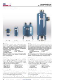
FA-12/15 FA-16-1,5 FA-67-18 FA-104-32W<br />
Flüssigkeitsabscheider<br />
Suction Line Accumulators<br />
General<br />
Refrigeration compressors draw refrigerant vapour from the evaporator<br />
and compress it to a state where it can easily be condensed into subcooled<br />
liquid. Depending on the operating conditions, situations can occur, when<br />
small amounts of liquid are carried-over from the evaporator and into<br />
the compressor. The consequence of this being liquid-hammer which will<br />
damage the compressor in the following components:<br />
� Suction Valve � Discharge Valves<br />
� Pistons and Connecting Rods � Gasket<br />
� Bearings<br />
<strong>ESK</strong> suction line accumulators incorporate the injection principle which has<br />
been tried and tested for many years. Even if the accumulator is full of liquid<br />
refrigerant, it is not possible for liquid to enter the compressor suction.<br />
Application<br />
In particular in compact plant with short suction lines, too low a suction<br />
superheat (below 7 K) will result in a loss of compressor oil pressure and<br />
a subsequent decrease in system capacity through displacement of oil by<br />
liquid refrigerant. <strong>ESK</strong> suction line accumulators protect the compressor<br />
against liquid hammer and its subsequent damage. The use of a suction line<br />
accumulator is strongly recommended under the following conditions:<br />
� Parallel connected compressors � Container cooling<br />
� Transport Refrigeration � Flooded evaporators<br />
� Two-stage plant � Reverse Cycle Operation<br />
� Use of hot-gas defrost � Superheat less 7 K<br />
� Heat pump systems<br />
Technical Specification<br />
<strong>ESK</strong>-Suction Line Accumulators are suitable for use with HFC- and HCFCrefrigerants<br />
(R134a, R404A, R507, R407A, R407C, R22 etc.). The accumulators<br />
are also released for an application with R410A.<br />
Max. Admissible Operating Pressure [bar] 28 20<br />
Admissible Operating Temperature [°C] 100 ...–10 –10 ... –50<br />
CATALOG 2012/13 � www.esk-schultze.de
Flüssigkeitsabscheider<br />
Suction Line Accumulators<br />
Auswahlgrundsätze<br />
Für die Auslegung sind die folgenden Kriterien maßgebend:<br />
1. Die Relation zwischen Anlagenfüllmenge und Abscheidervolumen:<br />
Verdichterhersteller empfehlen den Abscheider so zu bemessen, dass<br />
ca. 50 bis 70 % der Anlagenfüllmenge vom Abscheider aufgenommen<br />
werden können.<br />
2. Die Sauggasgeschwindigkeit VSG min. > 7 m/s sichert die Ölrückführung<br />
aus dem Abscheider.<br />
VSG opt. = 14 m/s, der Maximalwert VSG max = 20 m/s sollte nicht überschritten<br />
werden. Bei Leistungsregelung von Verdichtern kann die als VSG min.<br />
bezeichnete Angabe auf 5,6 m/s gesenkt werden (Grenzwert).<br />
Multi Flüssigkeitsabscheider<br />
<strong>ESK</strong>-Multiflüssigkeitsabscheider für maximal vier Verdichter werden anstelle<br />
von mehreren einzelnen Flüssigkeitsabscheidern oder individuell gestalteten<br />
Saugsammelleitungen in die Haupt-Saugleitung von Verbundsystemen<br />
eingesetzt. Jeder Verdichter wird auf einfache Weise strömungssymmetrisch<br />
korrekt angeschlossen. Durch das Injektorprinzip wird bei richtiger<br />
Zuordnung die einwandfreie Ölrückführung gewährleistet.<br />
Multiflüssigkeitsabscheider vermeiden fehlerhafte Installationen und verringern<br />
die Montagekosten. Bei Teillastbetrieb ist die Gasgeschwindigkeit<br />
in der Hauptsaugleitung zu beachten.<br />
Verdampfungstemperatur Kältemittel Bemerkung<br />
Evaporating temperature Refrigerant Remark<br />
to °C von/from to °C bis/to<br />
Selection<br />
For dimensioning suction line accumulators the following points must be<br />
considered:<br />
1. Relationship between accumulator volume and refrigerant charge.<br />
Compressor manufacturers recommend that 50 to 70 percent of the<br />
system charge should be able to fit into the accumulator.<br />
2. The suction gas velocity VSG min. > 7 m/s ensures an oil return from the<br />
acccumulator.<br />
VSG opt. = 14 m/s; the maximum value VSG = 20 m/s must not be exceeded.<br />
When a capacity regulation is used for the compressors, the VSG min.<br />
values can be reduced to 5,6 m/s (absolute limit).<br />
Multi Suction Line Accumulators<br />
<strong>ESK</strong> multi suction line accumulators can be used where several, individual suction<br />
line accumulators would normally be required. They may also be used for<br />
individually designed suction lines prior to the main suction line for parallel<br />
connected compressors. Each compressor is quite easily connected through<br />
separate suction circuits that should all produce the same pressure drop.<br />
<strong>ESK</strong> multi suction line accumulators help to avoid unnecessary installation<br />
work and hence reduce system costs. Under part load conditions, the gas<br />
velocity should be considered.<br />
Temperaturgrenzen Temperature Limits<br />
+ 10 – 15 R134a, R404A, R407A, R407C, R410A, R507, R22 Alle Ausführungen einsetzbar / All versions suitable<br />
– 15 – 50 R134a, R404A, R407A, R407C, R410A, R507, R22<br />
Installation<br />
FA ..W Flüssigkeitsabscheider<br />
Suction Line Accumulator<br />
Nur FA ..W oder FA .. bzw. MA .. mit Heizelementen<br />
Ölabscheider in der Druckleitung (5) erforderlich<br />
Only FA ..W or FA .., MA .. with heater elements<br />
Oil separator in discharge side (5) necessary<br />
MADE IN GERMANY<br />
Legende – Installation Legend – Installation<br />
FA ..W und MA ..Multi FA ..W and MA ..Multi<br />
1 vom Verdampfer from Evaporator<br />
2 zum Verdichter to Compressor<br />
2.2 Absaugdüse mit Saugrohr Nozzle with Suction Tube<br />
3 Vibrationsabsorber Vibration Eliminator<br />
4 Verdichter Compressor<br />
5 zum Verflüssiger to Condenser<br />
6 <strong>ESK</strong> Ölreguliersystem <strong>ESK</strong> Oil Control System<br />
erforderlich (siehe Schaltbilder) necessary (see diagrams)<br />
7 Flüssigkeitseintritt, -austritt; Liquid Inlet, -Outlet<br />
Wärmetauscher Heat Exchanger<br />
Flüssigkeitstemperatur > 20 °C Liquid Temperature > 20 °C<br />
� www.esk-schultze.de CATALOG 2012/13<br />
21<br />
<strong>ESK</strong> COMPONENTS FOR<br />
HFKW / HFCKW NATURAL REFRIGERANTS ACCESSORIES
<strong>ESK</strong> COMPONENTS FOR HFKW / HFCKW NATURAL REFRIGERANTS ACCESSORIES<br />
www.esk-schultze.de<br />
Installation MA..<br />
1 vom Verdampfer from Evaporator<br />
2 zum Verdichter to Compressor<br />
2.2 Absaugdüse mit Saugrohr Nozzle with Suction Tube<br />
3 Vibrationsabsorber Vibration Eliminator<br />
4 Verdichter Compressor<br />
5 zum Verflüssiger to Condenser<br />
6 <strong>ESK</strong> Ölreguliersystem <strong>ESK</strong> Oil Control System<br />
erforderlich (siehe Schaltbilder) necessary (see diagrams)<br />
Montage,<br />
nur vertikal!<br />
Vertical<br />
mounting only!<br />
Multi Flüssigkeitsabscheider<br />
Multi Suction Line Accumulators<br />
Auslegungsdaten Selection Data<br />
Multiabscheider Kälteleistung Q0 [kW] pro Verdichter Effektives<br />
bei 40 °C Verflüssigungstemperatur und 25 °C Sauggastemperatur Förder-<br />
Verdampfungstemperatur [°C], einstufiger Betrieb volumen<br />
Multi Accumulator Ref. Capacity Q0 [kW] for each Compressor Effective<br />
at 40 °C Condensing temperature and 25 °C Suctiongas temperature Displace-<br />
Evaporating temperature [°C], single stage operation ment<br />
Typ / Type R 404A, R 407A, R 407 C, R 507, R 22 R 410 A R 134 a Vo<br />
+5 0 –5 –10 –15 –20 –25 – 30 – 35 – 40 + 5 – 5 –15 –25 + 5 –10 – 20 – 30 m³ / h<br />
MA-35/4x22 Opt. 17,0 15,0 12,6 10,6 8,3 7,0 5,6 4,6 3,8 2,9 25,0 18,0 12,0 8,4 10,2 5,6 3,6 2,4 15,8<br />
Min. 8,5 7,5 6,3 5,3 4,2 3,6 3,0 2,3 1,9 1,5 12,5 9,0 6,0 4,2 5,1 2,8 1,8 1,2 7,9<br />
MA-42/4 x 28 Opt. 26,7 23,0 19,0 16,0 13,0 11,0 8,8 7,2 5,8 4,5 38,4 28,0 20,0 13,0 17,5 9,8 6,4 4,0 24,8<br />
MA-54/4 x 28 Min. 13,4 11,5 9,5 8,0 6,5 5,5 4,5 3,6 2,9 2,3 19,2 14,0 10,0 6,5 8,7 4,9 3,2 2,0 12,4<br />
MA-67/4 x 35 Opt. 44,0 36,0 32,0 26,0 22,0 18,0 14,0 12,0 10,0 8,0 64,0 46,0 32,0 22,0 26,8 15,0 9,8 6,2 40,6<br />
Min. 22,0 18,0 16,0 13,0 11,0 9,0 7,0 6,0 5,0 4,0 32,0 23,0 16,0 11,0 13,4 7,5 4,9 3,1 20,3<br />
MA-80/4 x 42 Opt. 62,0 52,0 46,0 36,0 30,0 25,0 20,0 16,0 14,0 10,0 94,0 66,0 46,0 32,0 40,0 22,0 14,0 9,0 57,2<br />
Min. 31,0 26,0 23,0 18,0 15,0 13,0 10,0 8,0 7,0 5,0 47,0 33,0 23,0 16,0 20,0 11,0 7,0 4,5 28,6<br />
Technische Daten Technical Data<br />
Multi Flüssigkeits- Eintritt Austritt Inhalt Abmessungen Gewicht DRL<br />
abscheider Lötanschluss innen Lötanschluss innen<br />
Multi Suction Line Inlet Solder Outlet Solder Volume Dimensions Weight PED<br />
Accumulator Connection O.D.S Connection O.D.S.<br />
Typ Ø SL Ø SL Ø SL Ø SL Ø D H R M Kategorie/Modul<br />
Type mm inch mm inch l (dm³) mm mm kg Category/Module<br />
MA-35/4 x 22 35 1-3/8 4 x 22 4 x 1-7/8 7,5 195 350 5/8”–18UNF M10 6,2 II / A1<br />
MA-42/4 x 28 42 1-5/8 4 x 28 4 x 1-1/8 7,5 195 390 5/8”–18UNF M10 6,2 II / A1<br />
MA-54/4 x 28 54 2-1/8 4 x 28 4 x 1-1/8 7,5 195 363 5/8”–18UNF M10 6,2 II / A1<br />
MA-67/4 x 35 67 2-5/8 4 x 35 4 x 1-3/8 1,0 300 405 5/8”–18UNF M12 15,0 II / A1<br />
MA-80/4 x 42 80 3-1/8 4 x 42 4 x 1-3/8 18,0 300 414 5/8”–18UNF M12 15,0 II / A1<br />
Ø SL = Saugleitungs-Außendurchmesser Ø SL = Suction Line Outside Diameter<br />
22<br />
Einsatz nur mit Heizelementen<br />
Application with heater elements only<br />
Maßzeichnung Dimensional Drawing<br />
CATALOG 2012/13 � www.esk-schultze.de
Flüssigkeitsabscheider<br />
Suction Line Accumulators<br />
Auslegungsdaten Selection Data<br />
Flüssigkeits- Kälteleistung Q0 [kW] Effektives<br />
abscheider bei 40 °C Verflüssigungstemperatur und 25 °C Sauggastemperatur Förder-<br />
Anschlussgröße Verdampfungstemperatur [°C], einstufiger Betrieb volumen<br />
Suction Line- Ref. Capacity Q0 [kW] Effective<br />
Accumulator at 40 °C Condensing Temperature and 25°C Suctiongas temperature Displace-<br />
Connection Size Evaporating temperature [°C], single stage operation ment<br />
Ø SL Ø SL Typ / Type R 404 A, R 407A, R 407 C, R 507, R 22 R 410 A R134 a Vo<br />
mm inch +5 0 –5 –10 –15 –20 –25 –30 –35 –40 +5 –5 –15 –25 +5 –10 –20 –30 m³/h<br />
12 – FA-12/15 Opt. 4,3 3,8 3,2 2,6 2,1 1,7 1,4 1,2 1,0 0,7 6,0 4,4 3,0 2,0 2,8 1,6 1,0 0,6 4,0<br />
Min. 2,2 1,9 1,6 1,3 1,1 0,9 0,7 0,6 0,5 0,4 3,0 2,2 1,5 1,0 1,4 0,8 0,5 0,3 2,0<br />
15 – FA-12/15 Opt. 7,1 6,2 5,4 4,6 3,5 2,9 2,4 1,9 1,6 1,2 10,4 7,4 5,2 3,6 4,7 2,6 1,8 1,1 6,6<br />
Min. 3,6 3,1 2,7 2,3 1,8 1,5 1,2 1,0 0,8 0,6 5,2 3,7 2,6 1,8 2,4 1,3 0,9 0,5 3,3<br />
16 5/8 FA-16… Opt. 8,4 7,6 6,4 5,2 4,1 3,3 2,8 2,3 2,0 1,4 12,0 8,6 6,0 4,0 5,5 3,0 2,0 1,2 7,8<br />
Min. 4,2 3,8 3,2 2,6 2,1 1,7 1,4 1,2 1,0 0,7 6,0 4,3 3,0 2,0 2,8 1,5 1,0 0,6 3,9<br />
18 – FA-18… Opt. 10,9 9,0 7,4 6,0 4,9 4,0 3,2 2,5 2,2 1,6 15,6 10,8 7,4 5,0 7,0 3,8 2,4 1,5 10,2<br />
Min. 5,5 4,5 3,7 3,0 2,5 22,0 1,6 1,3 1,1 0,8 7,8 5,4 3,7 2,5 3,5 1,9 1,2 0,8 5,1<br />
22 7/8 FA-22… Opt. 17,0 15,0 12,6 10,6 8,3 7,0 5,5 4,6 3,8 2,9 25,0 18,0 12,0 8,4 10,2 5,6 3,6 2,4 15,8<br />
Min. 8,5 7,5 6,3 5,3 4,2 3,6 3,0 2,3 1,9 1,5 12,5 9,0 6,0 4,2 5,1 2,8 1,8 1,2 7,9<br />
28 1-1/8 FA-28… Opt. 26,7 23,0 19,0 16,0 13,0 11,0 8,8 7,2 5,8 4,5 38,4 28,0 20,0 13,0 17,5 9,8 6,4 4,0 24,8<br />
Min. 13,4 11,5 9,5 8,0 6,5 5,5 4,5 3,6 2,9 2,3 19,2 14,0 10,0 6,5 8,7 4,9 3,2 2,0 12,4<br />
35 1-3/8 FA-35… Opt. 44 36 32 26 22 18 14,0 12 10 8 64 46 32 22 26,8 15,0 9,8 6,2 40,6<br />
Min. 22 18 16 13 11 9 7,0 6 5 4 32 23 16 11 13,4 7,5 4,9 3,1 20,3<br />
42 1-5/8 FA-42… Opt. 62 52 46 36 30 25 20 16 14 10 94 66 46 32 40 22 14 9,0 57,2<br />
Min. 31 26 23 18 15 13 10 8 7 5 47 33 23 16 20 11 7 4,5 28,6<br />
54 2-1/8 FA-54… Opt. 107 92 76 64 52 43 35 28 24 18 154 110 76 52 70 40 26 16 99,0<br />
Min. 53 46 38 32 26 22 18 14 12 9 77 55 38 26 35 20 13 8 49,5<br />
64 2-1/2 FA-67/64… Opt. 153 128 108 90 75 62 50 42 34 26 220 158 110 76 100 56 36 24 142<br />
Min. 77 64 54 45 38 31 25 21 17 13 110 79 55 38 50 28 18 12 71<br />
67 2-5/8 FA-67… Opt. 168 142 122 100 84 72 58 48 38 30 244 174 122 84 108 62 40 26 148<br />
Min. 84 71 61 50 42 36 29 24 19 15 122 87 61 42 54 31 20 13 74<br />
70 2-3/4 FA-67/70… Opt. 180 154 132 108 90 76 62 50 40 32 268 192 134 92 114 66 44 28 163,0<br />
Min. 90 77 66 54 45 38 31 25 20 16 134 96 67 46 57 33 22 14 81,5<br />
80 3-1/8 FA-80… Opt. 240 208 176 146 124 104 84 70 56 44 356 254 178 122 158 89 58 36 218<br />
Min. 120 104 89 73 62 52 42 35 28 22 178 127 89 61 79 45 29 18 109<br />
89 3-1/2 FA-80/89… Opt. 310 266 226 188 158 132 108 88 72 56 444 318 222 152 202 114 74 48 270<br />
Min. 155 133 113 94 79 66 54 44 36 28 222 159 111 76 101 57 37 24 135<br />
104 4-1/8 FA-104… Opt. 430 360 304 256 210 172 140 116 92 73 600 430 300 200 270 152 98 62 400<br />
Min. 215 180 152 128 105 86 70 58 46 37 300 215 150 100 135 76 49 31 200<br />
Ø SL = Saugleitungs-Außendurchmesser Einsatz nur mit Wärmetauscher oder Heizelementen<br />
Suction Line Outside Diameter Application with heat exchanger or heater elements only<br />
Auslegungsbeispiele Examples of Selection<br />
Beispiel Verdichter Verdichter Leistungs- Verd.- Auswahlkriterien <strong>ESK</strong>-Produkt<br />
Anschluss regelung temp.<br />
Example Compressor Compressor Capacity- Evap.- Selection, Information <strong>ESK</strong>-Product<br />
Connection Control temp.<br />
VH Ø SL Ø SL auf / to to<br />
No. m³/h mm inch % °C<br />
1 13 22 7/8 – –20<br />
R407A; Kälteleistung Qo = 4,7 kW;<br />
R407A; Capacity Qo = 4,7 kW<br />
FA-22W<br />
2 50 35 1-3/8 66 +5<br />
Pc/Po = 2,6; λ = 0,9; Vo = 0,9 x 50 = 45 m³ / h,<br />
Vo min = 30 m³ / h<br />
FA-42<br />
3 126 54 2-1/8 – –5<br />
90 kg R 22; Kälteleistung Qo = 83 kW<br />
90 kg R 22; Capacity Qo = 83 kW<br />
FA-67-32<br />
4 71 35 1-3/8 – – 40<br />
Verdichter zweistufig / Compressor two stage<br />
VHL = 71 m³ /h; Vo = VHL x 0,85 = 60 m³ /h<br />
FA-54WT oder / or<br />
FA-54-7W<br />
Verdichter, einstufig VO = λ x VH<br />
Compressor, single stage<br />
Verdichter, zweistufig VO = 0,85 x VHL<br />
Compressor, two stage<br />
VHL = Hubvolumen, Niederdruckstufe<br />
Displacement, low stage<br />
MADE IN GERMANY<br />
P/P 0 : Druckverhältnis Pressure ratio<br />
V0 : Effektives Fördervolumen Effective displacement<br />
VH : Theoretisches Hubvolumen Compressor displacement<br />
λ : Liefergrad Volumetric efficiency<br />
� www.esk-schultze.de CATALOG 2012/13<br />
23<br />
<strong>ESK</strong> COMPONENTS FOR<br />
HFKW / HFCKW NATURAL REFRIGERANTS ACCESSORIES
<strong>ESK</strong> COMPONENTS FOR HFKW / HFCKW NATURAL REFRIGERANTS ACCESSORIES<br />
www.esk-schultze.de<br />
Flüssigkeits- Abb. Lötanschluss Inhalt Abmessungen Gewicht DRL<br />
abscheider Innen<br />
Suction Line- Fig. Solder Connection Volume Dimensions Weight PED<br />
Acculmulator O. D. S.<br />
Typ Ø SL Ø SL Ø D H A Z M Kat./Modul<br />
Type mm inch l (dm³) mm mm mm mm kg Cat./Module<br />
FA-12/15 a 12 1/2 0,3 58 140 98 – – 0,6 –<br />
FA-16-1,5 b 16 5/8 1,5 100 250 60 – M10 2,0 –<br />
FA-16-2 b 16 5/8 2,0 100 320 60 – M10 2,5 I / A<br />
FA-16 c 16 5/8 2,3 125 252 60 – M10 2,0 I / A<br />
FA-18-2 b 18 – 2,0 100 322 60 – M10 2,5 I / A<br />
FA-22-2 b 22 7/8 2,0 100 329 60 – M10 2,7 I / A<br />
FA-22 c 22 7/8 3,5 125 382 60 – M10 2,7 I / A<br />
FA-22-7 c 22 7/8 7,1 195 325 100 – M10 6,0 I / A<br />
FA-28-2 b 28 1-1/8 2,0 100 336 60 – M10 2,9 I / A<br />
FA-28 c 28 1-1/8 3,5 125 388 60 – M10 2,9 I / A<br />
FA-28-7 c 28 1-1/8 7,5 200 329 100 – M10 6,0 II / A1<br />
FA-35 c 35 1-3/8 7,5 200 332 100 – M10 6,0 II / A1<br />
FA-42 c 42 1-5/8 7,5 200 338 100 – M10 6,0 II / A1<br />
FA-54-7 c 54 2-1/8 7,5 200 343 100 – M10 6,5 II / A1<br />
FA-54-9 c 54 2-1/8 9,5 195 417 100 – M10 7,5 II / A1<br />
FA-54T d 54 2-1/8 2 x 7,5 195 363 300 300 M12 12,5 II / A1<br />
FA-67/64T d 64 2-1/2 2 x 7,5 195 398 300 300 M12 14,0 II / A1<br />
FA-67T d 67 2-5/8 2 x 7,5 195 367 300 300 M12 13,0 II / A1<br />
FA-67/70T d 70 2-3/4 2 x 7,5 195 410 300 300 M12 14,0 II / A1<br />
FA-67-18 e 67 2-5/8 18 300 466 150 300 – 18,0 II / A1<br />
FA-80 e 80 3-1/8 18 300 471 150 300 – 18,0 II / A1<br />
FA-80/89 e 89 3-1/2 18 300 525 150 300 – 19,0 II / A1<br />
FA-80-32 f 80 3-1/8 32 273 807 207 – – 41,7 II / A1<br />
FA-89-32 f 89 3-1/2 32 273 864 262 – – 41,7 II / A1<br />
FA-104-32 f 104 4-1/8 32 273 812 221 – – 39,2 II / A1<br />
Ø SL = Saugleitungs-Außendurchmesser Ø SL = Suction Line Outside Diameter<br />
Flüssigkeitsabscheider<br />
Suction Line Accumulators<br />
Technische Daten Technical Data<br />
24<br />
a b c d e f<br />
CATALOG 2012/13 � www.esk-schultze.de
Flüssigkeitsabscheider mit Wärmetauscher<br />
Suction Line Accumulators with Heat exchanger<br />
Technische Daten Technical Data<br />
Flüssigkeits- Abb. Lötanschluss Inhalt Lötanschluss Abmessungen Gewicht DRL<br />
abscheider Innen Wärmeaustauscher<br />
Suction Line- Fig. Solder Connection Volume Solder Connection Dimensions Weight PED<br />
Acculmulator O. D. S. Heat exchanger<br />
Typ Ø SL Ø SL Ø FL Ø FL Ø D H A W Z M Kat./Modul<br />
Type mm inch l (dm³) mm inch mm mm mm mm mm kg Cat./Module<br />
FA-16W a 16 5/8 2,3 16 5/8 125 261 60 80 – M10 2,5 I / A<br />
FA-22W a 22 7/8 3,5 16 5/8 125 383 60 80 – M10 3,2 I / A<br />
FA-28W a 28 1-1/8 3,5 16 5/8 125 388 60 80 – M10 3,4 I / A<br />
FA-35W a 35 1-3/8 7,5 22 7/8 200 335 100 140 – M10 7,0 II / A1<br />
FA-42W a 42 1-5/8 7,5 22 7/8 200 339 100 140 – M10 7,3 II / A1<br />
FA-54-7W a 54 2-1/8 7,5 22 7/8 200 343 100 140 – M10 8,0 II / A1<br />
FA-54-9W a 54 2-1/8 9,0 22 7/8 195 420 100 140 – M10 9,0 II / A1<br />
FA-54WT b 54 2-1/8 2 x 7,5 22 7/8 195 361 300 140 300 M12 13,5 II / A1<br />
FA-67/64WT b 64 2-1/2 2 x 7,5 22 7/8 195 398 300 140 300 M12 14,0 II / A1<br />
FA-67WT b 67 2-5/8 2 x 7,5 22 7/8 195 365 300 140 300 M12 15,0 II / A1<br />
FA-67-18W c 67 2-5/8 18 22 7/8 300 466 150 140 300 – 19,0 II / A1<br />
FA-80W c 80 3-1/8 18 22 7/8 300 471 150 140 300 – 19,0 II / A1<br />
FA-80/89W c 89 3-1/2 18 22 7/8 300 525 150 140 300 – 20,0 II / A1<br />
FA-80-32W d 80 3-1/8 32 16 5/8 273 807 207 174 – – 44,0 II / A1<br />
FA-89-32W d 89 3-1/2 32 16 5/8 273 864 262 174 – – 44,0 II / A1<br />
FA-104-32W d 104 4-1/8 32 16 5/8 273 812 221 174 – – 41,5 II / A1<br />
Ø SL = Saugleitungs-Außendurchmesser Ø FL = Flüssigkeitsleitung<br />
Ø SL = Suction Line Outside Diameter Ø FL = Liquid Line<br />
a b c d<br />
1) Wärmetauscher / Heat exchanger<br />
MADE IN GERMANY<br />
� www.esk-schultze.de CATALOG 2012/13<br />
25<br />
<strong>ESK</strong> COMPONENTS FOR<br />
HFKW / HFCKW NATURAL REFRIGERANTS ACCESSORIES
<strong>ESK</strong> COMPONENTS FOR HFKW / HFCKW NATURAL REFRIGERANTS ACCESSORIES<br />
www.esk-schultze.de<br />
Allgemeines<br />
Im Ölsammelgefäß wird das vom Ölabscheider zugeführte Öl entgast,<br />
gekühlt und bevorratet. <strong>ESK</strong>-Ölsammelgefäße sind mit zwei Schaugläsern<br />
einschließlich einer Ölstandsanzeige (Schwimmerkugel) und mit zwei<br />
Absperrventilen ausgerüstet.<br />
Auswahl<br />
Die Baugröße der Ölsammelgefäße richtet sich nach der Anzahl der im<br />
Verbund geschalteten Verdichter, der Ölfüllung im Kurbelgehäuse, der<br />
Kältemittelmenge in der Anlage und den Betriebsbedingungen. In der<br />
folgenden Auswahltabelle wurden unsere Erfahrungen mit Verbundsystemen<br />
als Empfehlung zusammengefasst.<br />
Technische Spezifikation<br />
Pmax: Max. zulässiger Betriebsüberdruck [bar] 31 10<br />
tOSA: Zulässige Betriebstemperatur [°C] 100 ... –10 –10 ... –40<br />
tOSR: Zulässige Betriebstemperatur [°C] 140 ... –10 –10 ... –40<br />
tmax: 90°C (grüne Schauglas Schwimmerkugel)<br />
Installation<br />
Das Ölsammelgefäß sollte auf gleicher Höhe oder geodätisch höher als die<br />
Ölspiegelregulatoren angeordnet werden. Jeder Ölsammler ist grundsätzlich<br />
mit einem Heizelement auszurüsten (siehe Zubehör). Bei Stillstand der<br />
Verdichter ist das Heizelement einzuschalten, um eine Kältemittelverlagerung<br />
in den Ölsammler zu vermeiden.<br />
Inbetriebnahme<br />
Bei Inbetriebnahme ist das Sammelgefäß bis zum oberen Schauglas mit<br />
dem Verdichter Kältemaschinen-Öl zu füllen. Öl ist nur dann nachzufüllen,<br />
wenn der Ölstand unterhalb des unteren Schauglases absinkt.<br />
26<br />
Ölsammler und Kombinationen<br />
Oil Reservoirs and Combinations<br />
OSA-7,5 OSR-5-35 BOS2-R-54F<br />
General<br />
In the oil reservoir, any refrigerant trapped within the oil is boiled-off and<br />
the oil is cooled and kept available. <strong>ESK</strong> oil reservoirs are normally equipped<br />
with two sight glasses, with float ball level indicators, for upper and lower<br />
level indication, and with two shut off valves.<br />
Selection<br />
The size of oil reservoir required is determined by the number of compressors<br />
connected, compressor oil charge, system refrigeration charge<br />
and operating conditions. In the following selection chart, you will find a<br />
guideline based on our experience with parallel systems.<br />
Technical Specification<br />
Pmax: Max. Admissible Operating Pressure [bar] 31 10<br />
tOSA: Admissible Operating Temperature [°C] 100 ... –10 –10 ... – 40<br />
tOSR: Admissible Operating Temperature [°C] 140 ... –10 –10 ... – 40<br />
tmax: 90°C (green sight glass float ball)<br />
Installation<br />
The oil reservoir should be installed at the same level or higher as the oil<br />
level regulators. Every oil reservoir has to be equipped with a heater element<br />
(see accessories). During compressor stand still period the heater should be<br />
switched on to prevent refrigerant migration into oil reservoir.<br />
Start Up<br />
During start up of the system the oil reservoir should be charged with the<br />
compressor refrigeration oil up to the upper sight glass. If the oil level in the<br />
reservoir will fall under the lower sight glass level, oil have to be added.<br />
CATALOG 2012/13 � www.esk-schultze.de
Ölsammelgefäße<br />
Oil Reservoirs<br />
Auslegung Ölsammelgefäße Selection of Oil reservoirs<br />
Ölsammelgefäß Einstufige Anlagen Booster Systeme<br />
Oil Reservoir Single Stage Systems Booster Systems<br />
Typ VH VH VH<br />
Type No m³/h No m³/h No m³/h<br />
OSA-7,5 2 30 – 60 3 20 – 40 4 15 – 30<br />
OSA-11 2 60 – 130 3 40 – 90 4 40 – 60 Auf Anfrage /<br />
OSA-15 2 90 – 160 3 70 – 120 4 50 – 80 on request<br />
OSA-18 2 130 – 200 3 90 – 140 4 60 – 100<br />
OSA-32 2 200 – 350 3 140 – 280 4 100 – 180<br />
No = Gesamtzahl der Verdichter No = Total Number of Compressors<br />
VH = Volumenstrom je Verdichter von – bis (theoretisch) VH = Displacement per Compressor from – to (theoretical)<br />
Technische Daten Technical Data<br />
Ölsammel- Abb. Inhalt Anschluss Anschluss Abmessungen Anschluss Gewicht DRL<br />
gefäß Eintritt Austritt RV10B-1<br />
Oil Fig. Volume Connection Connection Dimensions Connection Weight PED<br />
Reservoir Inlet Outlet RV10B-1,5<br />
Typ Vt V1 V2 V3 Ø OL Ø OL Ø OL Ø OL Ø D A H E D C R M Kat./Modul<br />
Type l(dm³) l(dm³) l(dm³) l(dm³) mm inch mm inch mm mm mm mm mm mm kg Cat./Module<br />
OSA-7,5 a 7,5 2,9 5,6 – 10V 3/8 V 12V 1/2 V 200 70 345 76 136 226 5/8”-18 UNF M10 6,4 II / A1<br />
OSA-11 a 10,5 2,9 8,8 – 10V 3/8 V 16V 5/8 V 200 70 439 76 136 322 5/8”-18 UNF M10 7,8 II / A1<br />
OSA-15 a 15,0 2,9 12,3 – 10V 3/8 V 16V 5/8 V 200 70 568 76 136 451 5/8”-18 UNF M10 10,2 II / A1<br />
OSA-18 a 18,0 6,0 12,0 – 10V 3/8 V 16V 5/8 V 300 75 375 83 135 225 5/8”-18 UNF M10 13,9 II / A1<br />
OSA-32 b 32,0 6,0 15,0 25,5 22V 7/8 V 22V 7/8 V 273 120 790 230 400 591 5/8”-18 UNF – 36,2 II / A1<br />
Vt = Volumen gesamt Vt = Total Volume<br />
V = Rotalock Absperrventil, Löt V = Rotalock Shut Off Valve, ODS<br />
Ø OL = Ölleitung Außendurchmesser Ø OL = Oil Line Outside Diameter<br />
a b<br />
MADE IN GERMANY<br />
� www.esk-schultze.de CATALOG 2012/13<br />
27<br />
<strong>ESK</strong> COMPONENTS FOR<br />
HFKW / HFCKW NATURAL REFRIGERANTS ACCESSORIES
<strong>ESK</strong> COMPONENTS FOR HFKW / HFCKW NATURAL REFRIGERANTS ACCESSORIES<br />
www.esk-schultze.de<br />
Ölabscheider-Sammler<br />
Die kombinierten Ölabscheider-Sammler vom Typ OSR sind speziell für<br />
den Einsatz bei Hochdruck Ölreguliersystemen konzipiert. Im Gegensatz<br />
zu konventionellen Ölabscheidern besitzen sie kein Schwimmerventil.<br />
Ölabscheider-Sammler<br />
Oil Separator Reservoirs<br />
Oil separator reservoir<br />
The combination of oil separator and reservoir type OSR is especially<br />
designed to be used for high pressure oil regulation systems. In contrast to<br />
conventional oil separators it has no internal float valve.<br />
Technische Daten Technical Data<br />
Ölabscheider- Lötanschluss Inhalt Inhalt VH (m³/h) max. zul. Verdichter Hubvolumen, Gewicht DRL<br />
Sammler Innen Ölabscheider Ölsammler theo. bei 40°C Verflüssigungstemperatur<br />
Oil Separator Solder Conn. Volume Volume VH (m³/h) max. admissible compressor displace- Weight PED<br />
Reservoir O. D. Oil Separator Oil Reservoir ment theo. at 40°C condensing temperature<br />
Typ Ø DL Ø DL V Vt V1 V2 Verdampfungstemperatur / Evaporating temperature °C Kategorie/Modul<br />
Type mm inch l (dm³) l (dm³) l (dm³) l (dm³) 10 0 –10 –20 –30 kg Category/Module<br />
OSR-5-35/22 22 7/8 5,8 3,0 0,9 2,1 35 42 50 60 75 10,2 II / A1<br />
OSR-5-35/28 28 1-1/8 5,8 3,0 0,9 2,1 55 60 67 75 90 10,2 II / A1<br />
OSR-5-35 35 1-3/8 5,8 3,0 0,9 2,1 60 70 80 90 110 10,0 II / A1<br />
OSR 7-54/35 35 1 3/8 9,5 7,5 2,9 5,6 80 88 95 110 140 13,0 II / A1<br />
OSR 7-54/42 42 1 5/8 9,5 7,5 2,9 5,6 85 95 105 120 150 13,0 II / A1<br />
OSR 7-54 54 2 1/8 9,5 7,5 2,9 5,6 90 102 115 130 160 13,0 II / A1<br />
OSR-14-80/54 54 2 1/8 20,0 12,0 5,5 12,0 230 280 320 360 400 45,6 II / A1<br />
OSR-14-80/67 67 2 5/8 20,0 12,0 5,5 12,0 280 300 330 360 400 45,6 II / A1<br />
OSR-14-80 80 3 1/8 20,0 12,0 5,5 12,0 280 300 330 360 400 44,7 II / A1<br />
Ø DL = Druckleitungs-Außendurchmesser Ø DL = Discharge Line Outside Diameter<br />
Abmessungen Dimensions<br />
Ölabscheider-Sammler Abbildung Abmessungen<br />
Oil Separator Reservoir Drawing Dimensions<br />
Typ ØD H h 1 h 2 h3 h 4 A B<br />
Type mm mm mm mm mm mm mm mm<br />
OSR-5-35/22 a 159 597 460 75 194 – 142 –<br />
OSR-5-35/28 a 159 597 460 75 194 – 142 –<br />
OSR-5-35 a 159 575 460 75 194 – 120 –<br />
OSR 7-54/35 b 195 811 646 75 135 220 185 260<br />
OSR 7-54/42 b 195 811 646 75 135 220 184 260<br />
OSR 7-54 b 195 784 646 75 135 220 158 260<br />
OSR-14-80/54 c 273 848 568 215 345 – 248 294<br />
OSR-14-80/67 c 273 843 568 215 345 – 243 294<br />
OSR-14-80 c 273 807 568 215 345 – 207 294<br />
28<br />
a b c<br />
1) Olrückführung, 10 mm Lötanschluss / Oil return, 3/8“ Solder connection<br />
CATALOG 2012/13 � www.esk-schultze.de
Hochleistungs-Ölabscheider-Sammler<br />
High performance Oil Separator Reservoirs<br />
Hochleistungs-Ölabscheider-Sammler<br />
Die kombinierten Ölabscheider-Sammler vom Typ BOS2-R sind speziell für<br />
den Einsatz bei Hochdruck-Ölreguliersystemen konzipiert. Im Gegensatz zu<br />
konventionellen BOS2-Ölabscheidern besitzen sie kein Schwimmerventil.<br />
High performance Oil separator reservoir<br />
The combination of oil separator and reservoir type BOS2-R is especially<br />
designed to be used for high pressure oil regulation systems. In contrast to<br />
conventional BOS2 Oil separators it has no internal float valve.<br />
Technische Daten Technical Data<br />
Ölabscheider- Lötanschluss Inhalt Inhalt Inhalt VH (m³/h) max. zul. Verdichter Hubvolumen, DRL<br />
Sammler innen gesamt Ölabscheider Ölsammler theo. bei 40°C Verflüssigungstemperatur<br />
Oil Separator Solder Conn. Volume Volume Volume VH (m³/h) max. admissible Compressor displace- PED<br />
Reservoir O. D. total Oil Separator Oil Reservoir ment theo. at 40°C condensing temperature<br />
Typ Ø DL Ø DL V V BOS Vt V1 V2 Verdampfungstemperatur / Evaporating temp. °C Kat./Modul<br />
Type mm inch l (dm³) l (dm³) l (dm³) l (dm³) l (dm³) 10 0 – 10 – 20 – 30 Cat./Module<br />
BOS2-R-22F 22 7/8 3,8 1,6 2,2 0,4 1,5 35 40 45 50 65 I / A<br />
BOS2-R-35/28F 28 1-1/8 5,4 2,3 3,1 0,4 2,4 60 70 75 85 100 I / A<br />
BOS2-R-35F 35 1-3/8 5,4 2,3 3,1 0,4 2,4 90 100 115 130 160 I / A<br />
BOS2-R-54/42F 42 1-5/8 16,2 9,3 6,9 1,1 6,0 160 175 190 220 260 II / A1<br />
BOS2-R-54F 54 2-1/8 16,2 9,3 6,9 1,1 6,0 210 250 280 320 360 II / A1<br />
BOS2-R-80/67F 67 2-5/8 59,0 39,0 20,0 7,2 19,0 280 330 370 480 700 III / B + C1<br />
BOS2-R-80F 80 3-1/8 59,0 39,0 20,0 7,2 19,0 400 480 540 700 900 III / B + C1<br />
Abmessungen Dimensions<br />
Ölabscheider- Abb. Abmessungen Erst- Gewicht Ersatzpatrone<br />
Sammler Ölfüllung mit Dichtung<br />
Oil Separator Drawing Dimensions First Oil Weight Replacement<br />
Reservoir Charge element with gasket<br />
Typ Ø DF ØD H h1 h 2 h 3 h 4 A e Typ<br />
Type mm mm mm mm mm mm mm mm mm kg kg Type<br />
BOS2-R-22F a 140 100 553 66 216 251 466 95 150 0,8 7 FK2-22<br />
BOS2-R-35/28F b 140 100 828 111 391 426 741 117 220 1,2 11 FK2-35<br />
BOS2-R-35F b 140 100 828 111 391 426 741 95 220 1,2 11 FK2-35<br />
BOS2-R-54/42F c 230 160 985 111 158 388 868 152 310 2,0 32 FK2-54<br />
BOS2-R-54F c 230 160 985 111 158 388 868 125 310 2,0 32 FK2-54<br />
BOS2-R-80/67F d 273 273 1206 187 231 492 1052 243 460 8,0 78 FK2-80<br />
BOS2-R-80F d 273 273 1206 187 231 492 1052 207 460 8,0 77 FK2-80<br />
a b c d<br />
1) Service-Anschluss 7/16“<br />
Service connection 7/16“<br />
2) Ölrückführung RAV-1“-10<br />
Oil Return RAV-1“-10<br />
MADE IN GERMANY<br />
� www.esk-schultze.de CATALOG 2012/13<br />
29<br />
<strong>ESK</strong> COMPONENTS FOR<br />
HFKW / HFCKW NATURAL REFRIGERANTS ACCESSORIES
<strong>ESK</strong> COMPONENTS FOR HFKW / HFCKW NATURAL REFRIGERANTS ACCESSORIES<br />
www.esk-schultze.de<br />
OR-0-BC ORE2-0-BC ERM2-0-BC<br />
Allgemeines<br />
Beim Verbundbetrieb von Verdichtern werden Ölspiegelregulatoren zur<br />
Ölniveauregelung am Verdichter angebaut. Die Ölzufuhr erfolgt aus einem<br />
Ölsammelgefäß. Für die einwandfreie Funktion der Regulatoren ist die leistungsmäßig<br />
richtige Auswahl aller Systemkomponenten wichtig.<br />
Ölspiegelregulatoren stehen in mechanischer und elektronischer Ausführung<br />
zur Verfügung. In der Grundausführung werden die Regulatoren mit<br />
einem Drei-/Vierlochflansch und zur kompakten Installation mit einem<br />
Gewindefitting gefertigt. Zur Montage an den mannigfaltigen Schauglasausführungen<br />
werden Adapter und Kupplungsstück angeboten. (Siehe Seite 36)<br />
Mechanische Ölspiegelregulatoren<br />
Mechanische Ölspiegelregulatoren von <strong>ESK</strong> sind betriebssichere und robuste<br />
Komponenten. Präzisions-Schwimmerventile übernehmen die Regelung des<br />
Ölstandes im Verdichter-Kurbelgehäuse.<br />
Die einstellbare Version ist grundsätzlich bei Anlagen einzusetzen, in<br />
denen Verdichter mit unterschiedlichen Saugdrücken im Verbund arbeiten<br />
(Booster, Satellitenbetrieb).<br />
Montage<br />
Der auf Dichtigkeit und Funktion geprüfte Regulator wird mit dem<br />
erforderlichen Montagezubehör wie O-Ring, Befestigungsschrauben usw.<br />
ausgeliefert. Vor jedem Regulator ist ein Ölfilter zu montieren, um eine<br />
Verschmutzung des Schwimmerventils zu verhindern.<br />
Technische Spezifikation<br />
Max. zulässiger Betriebsüberdruck [bar] 31 10<br />
Zulässige Betriebstemperatur [°C] 100 ... –10 –10 ... – 40<br />
Ölspiegelregulatoren<br />
Oil Level Regulators<br />
General<br />
In multiple-compressor parallel systems, oil level regulators are installed<br />
to maintain an adequate oil level. Oil is fed conventionally from an oil reservoir.<br />
The correct selection of all components are necessary to guarantee<br />
the function of regulators.<br />
Oil level regulators are available in a mechanical or electronical version.<br />
The standard versions of regulators are manufactured with a 3-/4-bolt<br />
flange and for compact installations with a thread-fitting. For the installation<br />
on various compressor sight glass designs, <strong>ESK</strong> is offering a wide range<br />
of adapters and couplings. (See page 36)<br />
Mechanical Oil Level Regulators<br />
Mechanical oil level regulators from <strong>ESK</strong> are reliable and tough components.<br />
Precision float valves controls the oil level into compressor crankcase.<br />
The adjustable version is for use, when parallel connected compressors<br />
possibly work with different suction pressures (two stage systems, Booster’s<br />
and satellite operation).<br />
Installation<br />
The regulator has passed the check on function and tightness and will be<br />
delivered with the necessary mounting accessories, such as screw, O-rings,<br />
etc.. In front of every regulator, an oil strainer has to be mounted, to avoid<br />
soiling of the float valve seat.<br />
Technical Specification<br />
Max. admissible working pressure [bar] 31 10<br />
Admissible operating temperature [°C] 100 ... –10 –10 ... – 40<br />
Technische Daten Technical Data<br />
Ölspiegel- Ausführung Empfohlene Arbeits- Ölstand im Max. zul. Arbeits- Verdichteranschluss Inhalt<br />
Regulator druckdifferenz Schauglas druckdifferenz Ausführung<br />
Oil Level Version Recommended working Oil Level into Max. adm. working Compressor- Volume<br />
Regulator pressure difference Sight glass pressure difference Connection Version<br />
Typ / Type bar bar l (dm³)<br />
OR-0-BC Nicht einstellbar<br />
Nicht einstellbar<br />
1,5 Mitte<br />
Mitte<br />
4,2 3/4-Loch / 3/4-bolt<br />
ORL-OC, ORL-SN<br />
Not<br />
Not<br />
adjustable<br />
adjustable<br />
1,5 Center<br />
4,2 Gewinde / Thread<br />
ORE2-0-BC<br />
OREL-OC, OREL-SN<br />
einstellbar<br />
Einstellbar<br />
adjustable Adjustable<br />
1,5<br />
1,5<br />
Mitte<br />
Mitte<br />
Center<br />
Center<br />
6,5<br />
6,5<br />
3/4-Loch / 3/4-bolt<br />
Gewinde / Thread<br />
ORE2-0-BC-1 1,5 +3 + 3 / / –6 – 6 mm<br />
6,5 3/4-Loch / 3/4-bolt<br />
30<br />
CATALOG 2012/13 � www.esk-schultze.de<br />
0,8
Ölspiegelregulatoren<br />
Oil Level Regulators<br />
Abmessung Dimensions<br />
Ölspiegel- Abbildung Verdichter-Anschluss Schauglas Abmessungen<br />
Regulator Möglichkeiten Anzahl<br />
Oil Level Figure Compressor-Connection Sight glass Dimensions<br />
Regulator Possibilities quantity<br />
Direkt Adapter A D B H K DS<br />
Direct Adapter<br />
Typ / Type Stück / pieces mm mm mm mm mm mm<br />
OR-0-BC a x x 2 81 108 142 81 51 60<br />
ORL-OC, ORL-SN c *5 x 1 107 108 125 81 51 –<br />
ORE2-0-BC b x x 2 100 108 142 104 51 60<br />
OREL-OC, OREL-SN c x 1 107 108 125 104 51 –<br />
ORE2-0-BC-1 d x x 1 100 108 125 104 51 60<br />
a b c d<br />
Abb. Flansch<br />
View flange<br />
1 Schauglas mit Schwimmkugel<br />
2 Einstellmutter<br />
3 Anschluss der Ölzufuhr, Ø 10 mm Bördel<br />
4 Flansch<br />
*5 Ohne Einstellmutter (2)<br />
6 Adapter Typ OC oder SN<br />
Abb. Flansch<br />
View flange<br />
Einstellvorgang der Regulatoren<br />
Typ ORE2-0-BC, OREL-OC, OREL-SN, ORE2-0-BC-1<br />
Werkseinstellung: Mitte Schauglas<br />
Einstellbarkeit: +3/-6 mm<br />
Pro Linksumdrehung ‘x’ Ölstand 1,4 mm höher<br />
Pro Rechtsumdrehung ‘y’ Ölstand 1,4 mm tiefer<br />
Abb. Flansch<br />
View flange<br />
1 Sight glass with level indicator<br />
2 Adjusting nut<br />
3 Oil supply connection, flare 3/8’’<br />
4 Flange<br />
*5 Without adjusting nut (2)<br />
6 Adapter type OC or SN<br />
Adjusting Procedure of Regulators<br />
Type ORE2-0-BC, OREL-OC, OREL-SN, ORE2-0-BC-1<br />
Production setting: Center sight glass<br />
Adjusting range: +3/-6 mm<br />
Per left turn ‘x’ oil level 1/18 inch higher<br />
per right turn ‘y’ oil level 1/18 inch lower<br />
MADE IN GERMANY<br />
Abb. Flansch<br />
View flange<br />
� www.esk-schultze.de CATALOG 2012/13<br />
31<br />
<strong>ESK</strong> COMPONENTS FOR<br />
HFKW / HFCKW NATURAL REFRIGERANTS ACCESSORIES
<strong>ESK</strong> COMPONENTS FOR HFKW / HFCKW NATURAL REFRIGERANTS ACCESSORIES<br />
www.esk-schultze.de<br />
Neue elektronische Ölspiegelregulatoren<br />
Die neue Generation unserer elektronischen Ölspiegelregulatoren ERM /<br />
ERHD verbindet die positiven und bewährten Eigenschaften des Gehäuseaufbaus<br />
mit den vorteilhaften Eigenschaften des neuen Elektronik-Moduls<br />
und ist für 230 Volt bzw. für 24 Volt-Spannung erhältlich.<br />
Aufbau<br />
� Regulatorkörper aus Aluminium<br />
� Große Zuströmquerschnitte<br />
� Elektronikgehäuse aus Kunststoff<br />
� Schauglas für visuelle Füllstandskontrolle<br />
� Druck- und dichteunabhängige Istwerterfassung des Füllstandes<br />
� Regelniveau: Mitte Schauglas<br />
� Opto-elektronisches Messverfahren<br />
� Zwei Relais zur Signalisierung und<br />
Aufzeichnung von Betriebszuständen<br />
Sicherheit<br />
� Verstärkte LEDs führen zu verringerter Anfälligkeit<br />
durch verschmutztes Öl<br />
� Integriertes Notlaufprogramm sorgt selbst bei<br />
widrigsten Umständen für die Ölversorgung<br />
� Vierfach-Messpunkte ermöglichen die Signalüberwachung<br />
von Unter-, aber auch Überfüllung<br />
� Alarmfunktion bei Über-, Unterfüllung<br />
und bei aktiviertem Notlaufprogramm<br />
Erweiterter Einsatzbereich<br />
� 24 V-Ausführung ermöglicht den globalen Einsatz<br />
mit lokal notwendigem Trafo<br />
� Durch erhöhte Abtastraten und schnellste Reaktionszeiten<br />
besonders auch für höhere Drucklagen geeignet<br />
Achtung! Vor jedem Regulator ist ein Ölfilter zu montieren,<br />
um eine Verschmutzung des Magnetventils zu verhindern.<br />
ERM2-0-BC ERM3-OC<br />
Elektronische Ölspiegelregulatoren<br />
Electronic Oil Level Regulators<br />
New Electronic Oil Level Regulators<br />
The new generation of our Electronic Oil level Regulators ERM / ERHD<br />
unites the positive and proven features of regulator case design and the<br />
benefits of the new electronic module. 230-volt-models and as well 24-voltmodels<br />
are available. .<br />
Design<br />
� Regulator case made of aluminium<br />
� Wide cross sections for oil flow<br />
� Electronic case made of plastic<br />
� Sight glass for visual oil level control<br />
� Actual level value detection independent of pressure and density<br />
� Control level: middle sight glass<br />
� Opto-electronical measuring method<br />
� Two relays for signalisation / recording of<br />
system operating conditions<br />
Security<br />
� Reinforced LEDs lead to reduced sensitivity<br />
caused by contaminated oil<br />
� Integrated emergency operation program arranges<br />
for oil feed even in adverse conditions<br />
� Quadruple measure points enable signal control<br />
of under- but also overfilling<br />
� Alarm function for over-, underfilling and for<br />
activated emergency operation program<br />
Enlarged operation conditions<br />
� 24 V-execution enables globally operation with<br />
local conventional transformer<br />
� Caused by high-speed optical scannings and reaction<br />
times especially also for higher pressures capable<br />
Attention! In front of every regulator an oil strainer has<br />
to be mounted, to avoid soiling of the solenoid valve.<br />
Technische Daten, Modul Technical Data, Module<br />
Ölspiegel- Maximal zulässige Maximal zulässige Spannungs- Spannungs- Alarm-Relais Schutzart Gewicht<br />
regulator Medientemperatur Umgebungstemperatur versorgung toleranz Belastung<br />
Oil level Max. admissible Max. admissible Voltage supply Voltage tolerance Relais load Protection Weight<br />
regulator medium temperature ambient temperature class<br />
Typ / Type °C °C Volt-Phase-HZ Volt/Amp. kg<br />
ERM2 85 45 230-1-50/60 + / – 10 % Max. 250 / 5 IP 54 1,45<br />
ERM3 85 45 24-1-50/60 + / – 10 % Max. 250 / 5 IP 54 1,45<br />
32<br />
CATALOG 2012/13 � www.esk-schultze.de
Elektronische Ölspiegelregulatoren<br />
Electronic Oil Level Regulators<br />
Klemmenplan / Connection Scheme Elektrischer Anschlussplan / Wiring diagram<br />
Symbol Bedeutung Klemme Kontakt Bedeutung<br />
Meaning Terminal Contact Meaning<br />
L1 Phase 1 Magnetventil y1 7..8 Schaltrelais (Alarm / Warnung etc.)<br />
N Nullleiter / Neutral 2 Solenoid valve y1 9..10 Relay (Alarm / warning …)<br />
PE Erde / Ground 3<br />
PE Erde / Ground 4 y1 Magnetventil, Ölspiegelregulator<br />
N Nullleiter / Neutral 5 Spannungsversorgung / Solenoid valve, Oil Level Regulator<br />
L1 Phase 6 Voltage supply<br />
S1 Sicherung für den Steuerstromkreis<br />
Fuse for the control circuit<br />
Betriebszustände Operating modes<br />
ILC-Gerät Betrieb SG-Stand LED Status Kontakte Kommentar<br />
ILC-Unit Operation SG-Level Contacts Comments<br />
Ölspiegel- 7 8 Ölstand Mitte Schauglas<br />
regulatoren Start<br />
Typ ERM2-.. 9 10 Oil level middle sight glass<br />
Typ ERHD-..<br />
Typ ERM3-..<br />
Typ ERHD3-.. A<br />
7 8<br />
Ölstand sinkt,<br />
Füllvorgang ist aktiv<br />
9 10 Oil level drops,<br />
filling process is working<br />
Oil level 7 8<br />
regulators B<br />
type ERM2-..<br />
type ERHD-..<br />
9 10<br />
Unterfüllung, rote LED<br />
blinkt nach 120 Sekunden<br />
Under filling, red LED<br />
blinks after 120 seconds<br />
type ERM3-..<br />
type ERHD3-.. 7 8 Max. Stand, LED blinkt<br />
C<br />
9 10 Max. Level, LED blinks<br />
Das Notlaufprogramm The Emergency operation program<br />
���<br />
���<br />
���<br />
���<br />
Verunreinigung im Bereich MP 2 / MP3<br />
und Ölstand sinkt unter MP 4 –<br />
der Notlaufbetrieb startet<br />
Contamination in the area of MP 2/MP 3<br />
and the oil level decreases under MP 4 –<br />
emergency mode starts<br />
7 8<br />
9 10<br />
MADE IN GERMANY<br />
Rote und gelbe LED blinken –<br />
Kontakte 7/8 und 9/10 werden geöffnet:<br />
Getakteter Füllvorgang beginnt<br />
Red and yellow LED starts blinking –<br />
Contacts 7/8 and 9/10 are open:<br />
The pulsed oil refilling process is started<br />
� www.esk-schultze.de CATALOG 2012/13<br />
33<br />
<strong>ESK</strong> COMPONENTS FOR<br />
HFKW / HFCKW NATURAL REFRIGERANTS ACCESSORIES
Type ERM2-0-BC /<br />
ERM3-0-BC<br />
More security<br />
More efficiency<br />
Enlarged operation conditions<br />
24 VOLT<br />
EXECUTIONS<br />
AVAILABLE<br />
NOW<br />
The new generation of our<br />
Electronic Oil level Regulators ERM / ERHD
Elektronische Ölspiegelregulatoren<br />
Electronic Oil Level Regulators<br />
Technische Daten Technical Data<br />
Ölspiegel- Empfohlene Max. zulässige Verdichter-Anschluss- Max. zulässiger Volumen<br />
Regulator Arbeitsdruckdifferenz Arbeitsdruckdifferenz ausführung Arbeitsdruck<br />
Oil Level Recommended working Max. admissible working Compressor-Connection Max. admissible Volume<br />
Regulator pressure difference pressure difference Version working pressure<br />
Typ / Type bar bar bar l (dm³)<br />
ERM2-0-BC<br />
ERM3-0-BC 1,5 4,5 3/4-Loch / 3/4-bolt<br />
ERM2-OC<br />
ERM3-OC 1,5 4,5 Gewinde / Thread<br />
ERM2-SN<br />
ERM3-SN 1,5 4,5 Gewinde / Thread 45 0,2<br />
ERHD-0-BC<br />
ERHD3-0-BC 2 – 20 20,0 3/4-Loch / 3/4-bolt<br />
ERHD-OC<br />
ERHD3-OC 2 – 20 20,0 Gewinde / Thread<br />
ERHD-SN<br />
ERHD3-SN 2 – 20 20,0 Gewinde / Thread<br />
Maßzeichnungen Dimensional Drawings<br />
ERM2-0-BC ERHD-0-BC<br />
ERM3-0-BC ERHD3-0-BC<br />
ERM2-OC, ERM2-SN ERHD-OC, ERHD-SN<br />
ERM3-OC, ERM3-SN ERHD3-OC, ERHD3-SN<br />
MADE IN GERMANY<br />
� www.esk-schultze.de CATALOG 2012/13<br />
35<br />
<strong>ESK</strong> COMPONENTS FOR<br />
HFKW / HFCKW NATURAL REFRIGERANTS ACCESSORIES
<strong>ESK</strong> COMPONENTS FOR HFKW / HFCKW NATURAL REFRIGERANTS ACCESSORIES<br />
www.esk-schultze.de<br />
1.1/8”-UNF A 1.1/8”-UNEF MA<br />
1.3/4”-UN MR R<br />
Adaptersätze für Regulatormontage<br />
Adapter kits for Regulator Installation<br />
Installation<br />
Verdichter O-Ring Adapter O-Ring Regulator<br />
Compressor<br />
BO 3/4”-NPT TK 1.1/4”-UNF ME STD (inklusive / including)<br />
Adapter Typ Verdichter-Hersteller Verdichter-Serie Ölspiegel-Regulator Typ<br />
Adapter Type Compressor-Manufacturer Compressor line Oil Level Regulator Type<br />
MA BITZER 2K..2C, 4F..4C, 1<br />
R 8GC.., 8FC..<br />
BO BOCK F.., AM.., OR-0-BC<br />
MA HA/HG 12..36P 1<br />
CR CARRIER DA.., DR.., 5F.., 5H.. ORE2-0-BC<br />
A COPELAND DK.., DL..,<br />
R D..6J/T, D8.., D6D.., ORE2-0-BC-1<br />
TK 2 ZF.., ZS.., ZB..,<br />
MR ZR90...19M, ZR250...380<br />
ME 2 ZR94K..,190K; ZB50K..114K; ERM2-0-BC<br />
ZP90K..,182K<br />
MA DORIN K1.., H1 ERM3-0-BC<br />
R K7.., H7<br />
R FRASCOLD Z.., W.<br />
MA GOELDNER HS / HT / HZ / 0 12..34<br />
MA MANEUROP MT...V, LTZ...V, 1 SM, SZ<br />
A PRESTCOLD PK.., PL..,<br />
R P6..J/T, P8..,<br />
(1) alternativ Regulator Typ OREL-OC, ORL-OC oder ERM2-OC<br />
(2) Einsatz nur mit Regulator Typ ORE2-0-BC<br />
36<br />
(1) alternative regulator type OREL-OC, ORL-OC oder ERM2-OC<br />
(2) Application with regulator type ORE2-0-BC only<br />
CATALOG 2012/13 � www.esk-schultze.de
Ventile<br />
Valves<br />
Absperrventilsatz Typ AS<br />
Für einen besseren Service an Verbundanlagen mit Ölspiegelregulatoren<br />
stehen Absperrventilsätze für alle <strong>ESK</strong>-Regulatoren zur Verfügung. Der<br />
Absperrventilsatz besteht aus einem Absperrventil mit 10-mm-Lötanschluss<br />
(1) und einem Präzisionsadapter.<br />
Technische Daten<br />
Max. zulässiger Betriebsdruck [bar] 45<br />
Zulässige Betriebstemperatur [°C] 100<br />
Die Ventilsätze sind nicht für R 717 (NH3) und R 723 zugelassen.<br />
RV2-10B-1,5<br />
AS-Satz<br />
AS-Set<br />
Rückschlag- und Druckdifferenzventile<br />
Um das Öl aus dem Sammelgefäß den Verdichtern in ausreichender Menge<br />
zuführen zu können, ist eine Druckdifferenz zwischen dem Ölsammelgefäß<br />
und dem Verdichter-Kurbelgehäuse aufzubauen. Dazu wird ein Druckdifferenzventil<br />
RV2-10B/1,5 auf dem Ölsammelgefäß montiert und mit dem Saugdruck<br />
bei einstufigen Anlagen verbunden (Druckausgleichsleitung DAL).<br />
Bei zweistufigen Verdichter- und Booster-Anlagen muss die DAL an dem<br />
Zwischendruck angeschlossen werden, sofern die Verdichter-Kurbelgehäuse<br />
unter Zwischendruck stehen.<br />
Technische Daten<br />
Max. zulässiger Betriebsdruck [bar] 45<br />
Zulässige Betriebstemperatur [°C] 120<br />
Shut Off Valve Set Type AS<br />
To improve service on parallel systems with oil level regulators – functional<br />
check, replacement – shut off valve sets for all regulators are available. The<br />
shut off valve set consists of a shut off valve with 3/8“ solder connection (1)<br />
and a precision adapter.<br />
Technical Data<br />
Max. admissible operating pressure [bar] 45<br />
Admissible operating temperature [°C] 100<br />
The valve sets are not released for R 717 (Ammonia) and R 723 applications.<br />
� www.esk-schultze.de CATALOG 2012/13<br />
1<br />
Anschluss für Ölspiegelregulator<br />
Connection for the Oil Level Regulator<br />
Check and Pressure Valves<br />
In order to return oil from the reservoir back to the compressors at a sufficient<br />
flowrate, there must be a differential between reservoir pressure and<br />
crankcase pressure.<br />
A RV2-10B/1.5 is installed between the oil reservoir and the suction line on<br />
single stage plant.<br />
On two stage machines, where the crankcase is at an intermediate pressure<br />
and Booster systems, it is advisable to connect the equalizing line to this<br />
intermediate pressure.<br />
Technical Data<br />
Max. admissible operating pressure [bar] 45<br />
Admissible operating temperature [°C] 120<br />
MADE IN GERMANY<br />
Technische Daten Technical Data<br />
Rückschlag- und Druckventile Öffnungsdruck-Differenz Anschluss 1 Anschluss 2<br />
Check- and Pressure Valves Operating difference pressure Connection 1 Connection 2<br />
Typ / Type bar<br />
RV-10B-0,1 Rückschlagventil / 0,1 Ölabscheider-Rückführleitung / 10 mm Bördel / 3/8” Flare<br />
Check valve Oil Separator Return Line<br />
RV2-10B-1,5 Druckdifferenzventil / 1,5 Ölsammelgefäß / 10 mm Bördel / 3/8” Flare<br />
Pressure valve Oil reservoir<br />
RV2-10B-2,5 Druckdifferenzventil / 2,5 Ölsammelgefäß / 10 mm Bördel / 3/8” Flare<br />
Pressure valve Oil reservoir<br />
37<br />
<strong>ESK</strong> COMPONENTS FOR<br />
HFKW / HFCKW NATURAL REFRIGERANTS ACCESSORIES
<strong>ESK</strong> COMPONENTS FOR HFKW / HFCKW NATURAL REFRIGERANTS ACCESSORIES<br />
www.esk-schultze.de<br />
F-10L FF-16B<br />
Allgemeines<br />
<strong>ESK</strong>-Filter sind im gesamten Kältekreislauf einsetzbar. Die großflächigen<br />
Filter bestehen aus feinmaschigem Siebgewebe. Die Filter werden komplett<br />
aus Stahl gefertigt und sind für alle Kältemittel und Kältemaschinenöle einsetzbar.<br />
Als eine in der Praxis bewährte Anwendung hat sich der Einbau der<br />
Filter vor Ölspiegel-Regulatoren und vor elektronischen Expansionsventilen<br />
herausgestellt. Feste Partikel größer 0,05 mm werden ausgefiltert.<br />
Ölfilter<br />
Für die elektronischen Ölspiegelregulatoren vom Typ ERM und ERHD hat<br />
<strong>ESK</strong> einen Ölfilter mit einer Filterfeinheit von 5 µm konzipiert. Der Filter<br />
sichert die Magnetventilfunktion des elektronischen Regulators.<br />
Technische Spezifikation<br />
Max. zulässiger Betriebsüberdruck [bar] 31 10<br />
Zulässige Betriebstemperatur [°C] 100 ... –10 –10 ... – 40<br />
a b<br />
General<br />
<strong>ESK</strong> strainers can be applied anywhere in the refrigeration plant. <strong>ESK</strong>strainers<br />
comprise of fine grade mesh. Complete made of steel, these<br />
strainers are applicable for all refrigerants and refrigeration oils.<br />
An proven application is the installation of strainers in front of oil level<br />
regulators and electronical expansion-valves. Particles larger than 0,05 mm<br />
are strained.<br />
Oil Strainer<br />
For the protection of the electronic oil level control types ERM and ERHD<br />
<strong>ESK</strong> has designed a new strainer type. This new design will be able to pick<br />
up contaminants larger 5 µm. Therefore the filter is able to protect efficiently<br />
the solenoid valve of the regulator.<br />
Technical Specification<br />
Max. admissible working pressure [bar] 31 10<br />
Admissible operating temperature [°C] 100 ... –10 –10 ... – 40<br />
Filter<br />
Strainer<br />
Technische Daten Technical Data<br />
Filter Typ Abb. Anschluss Durchmesser außen Inhalt Abmessungen Anschlussart Gewicht<br />
Strainer Type Fig. Connection O.D. Volume Dimensions Connecting Version Weight<br />
Ø T mm Ø T inch l (dm³) Ø D mm L mm 1 kg<br />
F- 6B a 6 1/4 0,1 77 74 0,5<br />
F-10B a 10 3/8 0,1 77 82 0,5<br />
F-12B a 12 1/2 0,1 77 88 Bördel / Flare<br />
0,5<br />
F-16B a 16 5/8 0,1 77 94 0,5<br />
F-18B a 18 3/4 0,1 77 104 0,5<br />
F-10L a 10 3/8 0,1 77 70 0,5<br />
F-12L a 12 – 0,1 77 76 0,5<br />
F-1/2”L a – 1/2 0,1 77 76 Löt / Solder 0,5<br />
F-16L a 16 5/8 0,1 77 88 Löt / Solder<br />
0,5<br />
F-18L a 18 – 0,1 77 94 0,5<br />
F-22L a 22 7/8 0,1 77 106 0,5<br />
F-28L a 28 1-1/8 0,2 108 119 1,0<br />
F-35L a 35 1–3/8 0,2 108 131 1,0<br />
Ölfilter / Oil Strainer<br />
FF-10B<br />
FF-16B<br />
b<br />
b<br />
10<br />
16<br />
3/8<br />
5/8<br />
0,4<br />
0,4<br />
77<br />
77<br />
171<br />
179<br />
Bördel / Flare<br />
Bördel / Flare<br />
Bördel / Flare<br />
1,0<br />
1,0<br />
38<br />
CATALOG 2012/13 � www.esk-schultze.de
Geräuschdämpfer<br />
Discharge Line Mufflers<br />
GD-16 GDX-18 GDS-35 GDX-35 GDX-67 GD-80<br />
Allgemeines<br />
Beim Einsatz von Hubkolben- und Schraubenverdichtern entstehen Druckgaspulsationen,<br />
die sich in der Anlage als störendes Geräusch auswirken<br />
können. Zur Reduktion der Gaspulsation hat sich der Einbau von<br />
Geräuschdämpfern in die Druckleitung bewährt. Folgende Diagramme<br />
veranschaulichen die Verminderung der Pulsation, die sich positiv durch<br />
eine Reduzierung des Gesamtschalldruckes auswirkt.<br />
Ohne <strong>ESK</strong> Geräuschdämpfer<br />
Without <strong>ESK</strong> Muffler<br />
Anwendung<br />
<strong>ESK</strong>-Geräuschdämpfer sind für den Betrieb mit HFKW-, HFCKW- und mit<br />
natürlichen Kältemitteln (auf Anfrage) einsetzbar. Geräuschdämpfer reduzieren<br />
die Gaspulsation, aber keinen Körperschall.<br />
Technische Spezifikation<br />
Max. zulässiger Betriebsüberdruck [bar] 31 10<br />
Zulässige Betriebstemperatur [°C] 140 ... –10 –10 ... –40<br />
Geräuschdämpfer, einstellbar<br />
Die einstellbaren Geräuschdämpfer der Serie GDX eignen sich besonders<br />
für folgende Anwendungen:<br />
� Verdichter Verbundanlagen (zentrale Druckleitung)<br />
� Schraubenverdichteranlagen<br />
� leistungsgeregelte Verdichter<br />
� individuelle Rohrleitungsführung<br />
� große Verdampfungs-Temperaturbereiche<br />
(Kältemittelmassenstrom/Druckverhältnis)<br />
� installierte Anlagen mit Geräuschproblemen<br />
Durch die Einstellbarkeit auf der Ein- und/oder Austrittsseite ist bei den<br />
genannten Bedingungen eine optimale Beeinflussung der Pulsationsdämpfung<br />
erreichbar.<br />
General<br />
By using reciprocating or screw compressors pressure pulsations will be<br />
introduced into the discharge line. These pulsations may cause annoying<br />
noise and vibration throughout the connected pipe work. To reduce these<br />
pressure pulsations it is recommended to fit a muffler into the discharge<br />
line. The results of fitting such a muffler are shown in the diagrams below.<br />
Mit <strong>ESK</strong> Geräuschdämpfer<br />
With <strong>ESK</strong> Muffler<br />
MADE IN GERMANY<br />
Application<br />
<strong>ESK</strong> mufflers are suitable for use with HFC, HCFC refrigerants and natural<br />
refrigerants on request. Discharge line mufflers reduce gas pulsations but<br />
do not prevent the transmission of mechanical noise or vibration.<br />
Technical Specification<br />
Max. admissible working pressure [bar] 31 10<br />
Admissible operating temperature [°C] 140 ... –10 –10 ... –40<br />
Discharge Line Muffler, adjustable<br />
The adjustable discharge line mufflers of the GDX range are especially<br />
suitable for the following application:<br />
� Compressor parallel systems (central discharge line)<br />
� Screw compressor systems<br />
� Capacity controlled compressors<br />
� Individual line arrangement<br />
� Wide evaporating temperature ranges<br />
(ref. mass flow, pressure ratio)<br />
� Fixed system with noise problems<br />
In respect of the adjustement at the inlet- and/or outlet side,<br />
a high efficient influence of pulsation reduction is reachable.<br />
� www.esk-schultze.de CATALOG 2012/13<br />
39<br />
<strong>ESK</strong> COMPONENTS FOR<br />
HFKW / HFCKW NATURAL REFRIGERANTS ACCESSORIES
<strong>ESK</strong> COMPONENTS FOR HFKW / HFCKW NATURAL REFRIGERANTS ACCESSORIES<br />
www.esk-schultze.de<br />
Auswahlgrundsätze<br />
Die Anschlussgröße DL des Geräuschdämpfers sollte mit dem Druckleitungsquerschnitt<br />
übereinstimmen, der nach kältetechnischen Regeln<br />
bestimmt wurde. Für den Einbau in Seriengeräte wird eine versuchstechnische<br />
Erprobung empfohlen.<br />
Für Seriengeräte können wir durch eine besondere<br />
Bauteilzuordnung (Lochblech-Typ, -Anzahl, -Abstände)<br />
problemlösende Sonderausführungen fertigen.<br />
Einstellung und Einbau der GDX-Geräte Adjusting and Installation of the GDX-Mufflers<br />
Auslegungsbeispiele Examples of Selection<br />
Beispiel Verdichter Verdichter- Leistungs- Verdichtungs- Auswahlkriterien <strong>ESK</strong>-Produkt<br />
Anschluss regelung temperatur<br />
Example Compressor Compressor- Capacity- Evaporating Selection, Information <strong>ESK</strong>-Product<br />
Connection Control temperature<br />
VH Ø DL Ø DL auf / to to<br />
No. m³/h mm inch % °C<br />
Bauraum<br />
1 38 22 7/8 – – 5 °C Mounting space<br />
Selection<br />
The connection size DL of the muffler should correspond to the size of the<br />
discharge line, which has been selected according to the technical rules of<br />
refrigeration. For equipment installation of discharge line mufflers laboratory<br />
tests are recommended.<br />
Special solutions for standard equipment<br />
manufacturer are possible by combination of<br />
baffle-type, -numbers and -distance.<br />
GD-22 / GDS-22<br />
Leistungsanpassung möglich GDX-22<br />
2 38 22 7/8 30 – 5 °C Capacity adjustment possible einstellbar / adjustable<br />
*2-stufig; HD-Stufe / VH HD = 42 m³ / h<br />
3 127* 35 1-3/8 – – 40°C *2-stage; HP-stage / VH HP = 42 m³ / h<br />
Geräuschdämpfer<br />
Discharge Line Mufflers<br />
Horizontale Installation GD.. / GDX.. Vertikale Installation GD.. / GDX..<br />
Horizontal installation Vertical installation<br />
GDX Horizontale Einbauposition Vor dem Einstellen Nach dem Einstellen<br />
Horizontal Position of installation Before Adjustment After Adjustment<br />
1 – Einstellspindel (GDX-67 2 x Eintrittsseite, GDX-16 / GDX-18 1x Eintrittsseite)<br />
2 – Schrader-Anschluss für Rohr Ø 6 mm<br />
3 – Einstelleinheit<br />
8 – Einbau horizontal, Druckanschluss - DL - unten<br />
Einstellvorgang auf der Eintritts- und/oder Austrittsseite<br />
A – Verschlusskappe (4) und Konterscheibe (5) lösen.<br />
B – Gasfluss drosseln (6) oder vergrößern (7).<br />
C – Druckabfall ist über die Schraderventile (2) messbar.<br />
D – Konterscheibe (5) einsetzen und die Einstellung sichern.<br />
E – Verschlusskappe (4) festziehen.<br />
40<br />
1 Vibrationsabsorber 1 Vibration Eliminator<br />
2 Abstützung 2 Support<br />
3 Geräuschdämpfer 3 Discharge Line Muffler<br />
nicht empfohlen<br />
not recommended<br />
empfohlen<br />
recommended<br />
1 – Adjusting screw (GDX-67 2x inlet side, GDX-16 / GDX-18 1x inlet side)<br />
2 – Schrader connection for tube 1/4‘‘<br />
3 – Adjusting unit<br />
8 – Horizontal installation, DL-connection at the bottom<br />
Adjusting procedure on the inlet- and/or outlet-side<br />
A – Remove the seal cap (4) and the locking screw (5).<br />
B – Reduce (6) or increase (7) the gasflow.<br />
C – Pressure loss could be measured on Schrader valves (2).<br />
D – Fix the locking screw (5) to prevent a change of the adjustment.<br />
E – Lock seal cap (4).<br />
GD-22 / GDS-22<br />
CATALOG 2012/13 � www.esk-schultze.de
Geräuschdämpfer<br />
Discharge Line Mufflers<br />
Technische Daten Technical Data<br />
Geräuschdämpfer Lötanschluss Innen Inhalt Abmessungen Gewicht Richtwert DRL<br />
Discharge Line Muffler Solder Connection O.D.S Volume Dimensions Weight Standard value PED<br />
Typ Ø DL Ø DL Ø D L VH Kategorie/Modul<br />
Type mm inch l (dm³) mm mm kg m³ / h Category/Module<br />
GD-10 10 3/8 0,3 58 182 0,5 7,5 –<br />
GD-12 12 – 0,3 58 188 0,5 12 –<br />
GD-1/2” – 1/2 0,3 58 188 0,5 12 –<br />
GD-15 15 – 0,3 58 196 0,5 18 –<br />
GD-16 16 5/8 0,3 58 199 0,6 23 –<br />
GD-18 18 – 0,3 58 205 0,6 30 –<br />
GD-3/4” – 3/4 0,3 58 205 0,6 30 –<br />
GDS-22 22 7/8 0,3 58 217 0,6 42 –<br />
GD-22 22 7/8 1,1 125 198 1,6 42 –<br />
GD-28 28 1–1/8 1,1 125 212 1,6 74 –<br />
GDS-35 35 1–3/8 1,1 125 222 1,6 110 –<br />
GD-35 35 1–3/8 2,3 125 344 2,4 110 I / A<br />
GD-42 42 1–5/8 2,3 125 353 2,6 170 I / A<br />
GD-54 54 2–1/8 3,6 125 490 3,9 290 I / A<br />
GD-67/64 64 2–1/2 3,6 125 560 4,6 350 I / A<br />
GD-67 67 2–5/8 3,6 125 497 5,0 450 I / A<br />
GD-67/70 70 2–3/4 3,6 125 585 5,0 450 I / A<br />
GD-80/76 76 3 3,6 125 585 5,0 550 I / A<br />
GD-80 80 3–1/8 3,6 125 505 5,0 650 I / A<br />
Einstellbar / Adjustable<br />
GDX-18/12 12 1/2 0,8 108 188 2,2 –<br />
GDX-16 16 5/8 0,8 108 165 2,0 –<br />
GDX-18 18 – 0,8 108 168 2,2 –<br />
GDX-22 22 7/8 1,5 108 268 3,0 –<br />
GDX-28 28 1–1/8 1,5 108 282 3,0 –<br />
GDX-35 35 1–3/8 1,5 108 294 3,0 –<br />
GDX-42 42 1–5/8 1,5 108 360 3,0 –<br />
GDX-54 54 2–1/8 2,0 155 258 4,0 I / A<br />
GDX-67/64 64 2–1/2 2,0 155 332 5,0 I / A<br />
GDX-67 67 2–5/8 2,0 155 269 4,0 I / A<br />
GDX-67/70 70 2–3/4 2,0 155 358 5,0 I / A<br />
GDX-67/76 76 3–3/4 2,0 155 368 5,0 I / A<br />
GDX-67/80 80 3–1/8 2,0 155 378 5,0 I / A<br />
Ø DL = Druckleitungs-Außendurchmesser Ø DL = Discharge Line Outside Diameter<br />
VH = theo. Verdichter Fördervolumen VH = theo. Compressor displacement<br />
Maßzeichnung Dimensional Drawing Druckabfall Pressure Drop<br />
∆ P [bar] Kältemittel<br />
Refrigerant<br />
0,3 R 134 a<br />
0,4 R 407 C / R 22<br />
0,5 R 404 A / R 407 A / R 507<br />
∆ P = Druckabfall gerundet bei VH,<br />
0°C Verdampfungstemperatur<br />
40°C Verflüssigungstemperatur<br />
∆ P = average pressure drop at VH,<br />
0°C evaporating temperature<br />
40°C condensing temperature<br />
MADE IN GERMANY<br />
� www.esk-schultze.de CATALOG 2012/13<br />
41<br />
<strong>ESK</strong> COMPONENTS FOR<br />
HFKW / HFCKW NATURAL REFRIGERANTS ACCESSORIES
<strong>ESK</strong> COMPONENTS FOR HFKW / HFCKW NATURAL REFRIGERANTS ACCESSORIES<br />
www.esk-schultze.de<br />
S-1,5 S-2,3 SGS-11 SGS-32<br />
Allgemeines<br />
FIüssigkeitssammler dienen zur Kältemittel-Flüssigkeitsvorlage für den<br />
Verdampfer und sollen im Servicefall die gesamte Anlagenfüllmenge<br />
aufnehmen.<br />
Auswahl<br />
Entsprechend der Anlagenfüllmenge ist der Flüssigkeitssammler auszuwählen.<br />
Die max. zugelassenen Sammler-Füllmengen sind in der Tabelle – Technische<br />
Daten – genannt. Aus dem Auswahldiagramm kann bei nicht bekannter<br />
Füllmenge ein Richtwert für die Sammlergröße abgelesen werden.<br />
Technische Spezifikation<br />
Max. zulässiger Betriebsüberdruck [bar] 31 10<br />
Zulässige Betriebstemperatur [°C] 100 ... –10 –10 ... –40<br />
Flüssigkeitssammler<br />
Liquid Receivers<br />
General<br />
The liquid receiver acts as a stock of liquid refrigerant for the evaporators.<br />
However, the receiver should be sized to hold the full system charge during<br />
service work.<br />
Selection<br />
The receiver should be sized according to the amount of refrigerant in the<br />
plant. The maximum admissible volume of liquid refrigerant for each size<br />
of receiver is shown in the table –Technical Data–. If the system charge is<br />
not known, guidelines for receiver selection can be found in the diagram.<br />
Technical Specification<br />
Max. Admissible Operating Pressure [bar] 31 10<br />
Admissible Operating Temperature [°C] 100 ... –10 –10 ... –40<br />
Beispiele für Sondergeräte in Serienfertigung (OEM) Examples for special components in series production (OEM)<br />
42<br />
MF-FA-22-3/S-12-3<br />
Multifunktionsgerät, Abscheider/Sammler<br />
SGS-5,7 Multi function unit, Separator/ Receiver S-2,6/12-12<br />
CATALOG 2012/13 � www.esk-schultze.de
Flüssigkeitssammler<br />
Liquid Receivers<br />
Flüssigkeits- Inhalt Abb. Gewicht Löt-Anschluss Löt-Anschluss Abmessungen DRL<br />
sammler Eintritt Austritt<br />
Liquid Volume Fig. Weight Solder-Con- Solder-Con- Dimensions PED<br />
Receiver nection / Inlet nection / Outlet<br />
Typ / Type Vt V1 V2 V3 Ø FL Ø FL Ø FL Ø FL Ø D A H G D E R Kat. /Modul<br />
l (kg**) l l l kg mm inch mm inch mm mm mm mm mm mm mm Cat. /Module<br />
S-1,5/ 1/2“-10 1,5 – – – a 2,0 – 1/2 10 3/8 108 60 241 – – – – –<br />
S-2/ 12-12 2,0 – – – a 2,6 12 – 12 – 108 60 314 – – – – I / A<br />
S-2,3/ 12-12V 2,3 – – – b 2,3 12 – 12 1/2 125 70 301 – – – 5/8“-18UNF I / A<br />
S-3,8/ 12-12V 3,8 – – – b 3,2 12 – 12 1/2 125 70 415 – – – 5/8“-18UNF I / A<br />
S-7,5/ 16-16V 7,5 – – – b 7,0 16 5/8 16 5/8 200 140 357 – – – 5/8“-18UNF II / A1<br />
SGS-7,5/ 16W-12V 7,5 2,9 5,6 – c 7,0 16 5/8 12 1/2 200 70 361 76 136 226 5/8“-18UNF II / A1<br />
SGS-11/ 16W-16V 11,0 2,9 8,8 – c 9,0 16 5/8 16 5/8 200 70 457 76 136 226 5/8“-18UNF II / A1<br />
SGS-18/ 22W-22V 18,0 6,0 12,0 – d 13,0 22 7/8 22 7/8 300 75 391 – 135 226 5/8“-18UNF II / A1<br />
SGS-32/ 22W-22V 32,0 6,0 15,0 25,5 e 36,7 22 7/8 22 7/8 273 120 790 – 400 591 5/8“-18UNF II / A1<br />
Vt = Volumen gesamt Vt = Total Volume<br />
Ø FL = Flüssigkeitsleitung Außendurchmesser Ø FL = Liquid Line Outside Diameter<br />
W = Rotalock Winkel-Lötadapter W = Rotalock Fitting ODS<br />
V = Rotalock Absperrventil Löt V = Rotalock Shut Off Valve, ODS<br />
** Füllmenge in kg für unter 95% des Sammlervolumens bei ** Ref. charge in kg, for less than 95% receiver<br />
50 °C Flüssigkeitstemperatur (R134a, R404A, R22) volume at 50 °C liquid temperature (R134a, R404A, R22)<br />
Richtwert für R404A<br />
Reference values for R404A<br />
QV Kälteleistung [kW] Cooling capacity [kW]<br />
V1 Sammlervolumen [l] Receiver volume [l]<br />
Maßzeichnung Dimensional drawing<br />
a b c d e<br />
MADE IN GERMANY<br />
Technische Daten Technical Data<br />
� www.esk-schultze.de CATALOG 2012/13<br />
43<br />
<strong>ESK</strong> COMPONENTS FOR<br />
HFKW / HFCKW NATURAL REFRIGERANTS ACCESSORIES
<strong>ESK</strong> COMPONENTS FOR HFKW / HFCKW NATURAL REFRIGERANTS ACCESSORIES<br />
www.esk-schultze.de<br />
Füllstandskontrolle ILC<br />
Die Module sind in unterschiedlichen Ausführungen lieferbar und werden<br />
an die entsprechenden Behälter und Apparate angebracht. Zusätzliche<br />
Bausätze mit Prismenschaugläsern werden angeboten.<br />
Stromlaufplan: Siehe Seite 33<br />
ILC Intelligente Füllstandskontrolle<br />
ILC Intelligent Level Control<br />
Intelligent level control ILC<br />
The modules are available in different executions to be mounted on the<br />
correspondent vessels and equipment. Additional sets including prism<br />
sight glasses are available.<br />
Wiring diagram: See page 33<br />
Technische Daten Technical Data<br />
Bausatz Typ Lieferumfang Montagemöglichkeit<br />
Installation kit type Scope of Delivery Mounting Options<br />
LC-H Elektronik-Modul LC-H/ LC-L <strong>ESK</strong>-Geräte mit eingebautem Prismenschauglas<br />
LC-L Electronic module LC-H/ LC-L <strong>ESK</strong> devices with build in prism sight glasses<br />
LC-L-MA Elektronik-Modul LC-H/ LC-L mit 3-Loch- <strong>ESK</strong>-Schaugläser in Flüssigkeits- und Ölsammlern<br />
Prismenschauglas, MA-Adapter und Schauglasbatterie SB5<br />
LC-L-MA Electronic module LC-H/ LC-L with 3-bolt <strong>ESK</strong> sight glasses in liquid receivers and oil reservoirs<br />
prism sight glass and MA adapter and sight glass battery SB5<br />
LC-L-MA-L<br />
LC-L-MR<br />
Elektronik-Modul LC-L mit 3-Loch-<br />
Prismenschauglas, MA-L-Adapter<br />
Für Ölsammler OSA-7,5 /11 / 18<br />
Electronic module LC-L with 3-bolt<br />
prism sight glass and MA-L adapter<br />
For oil reservoirs OSA-7,5 / 11 / 18<br />
LC-L-MR Elektronik-Modul LC-H/ LC-L mit 3-Loch-<br />
Prismenschauglas und MR-Adapter<br />
Behälter mit einem 1-3/4” MPT Anschluss (Rotalockanschluss)<br />
LC-L-MR Electronic module LC-H/ LC-L with 3-bolt<br />
prism sight glass and MR adapter<br />
Vessels equipped with an 1-3/4” MPT (Rotalock-Stud) connection<br />
LC-H/M-ME Elektronik-Modul LC-H/M / LC-L/M mit 3-Loch-<br />
Prismenschauglas, ME-Adapter<br />
Behälter mit einem 1-1/4 MPT Anschluss (Rotalockanschluss)<br />
Electronic module LC-H/ LC-L with 3-bolt<br />
prism sight glass and ME adapter<br />
Vessels equipped with an 1-1/4” MPT (Rotalock-Stud) connection<br />
Beispiele für Betriebszustände Examples of operating modes<br />
ILC-Gerät Betrieb SG-Stand LED Status Kontakte Kommentar<br />
ILC-Unit Operation SG-Level Contacts Comments<br />
Füllstandskontrolle 7 8 System arbeitet<br />
Minimum/Mitte Start<br />
Typ LC-L/M 9 10 System operable<br />
Low Level Control 7 8 Stand unter Mitte<br />
Centre A<br />
Type LC-L/M 9 10 Level below centre<br />
44<br />
CATALOG 2012/13 � www.esk-schultze.de
ILC Intelligente Füllstandskontrolle<br />
ILC Intelligent Level Control<br />
Maß- und Montagezeichnungen Dimensional and Installation Drawings<br />
LC-L-MR<br />
LC-H/M-ME<br />
LC-L-MA<br />
LC-L-MA-L<br />
1 Elektronik-Modul ILC 5 MR-Adapter<br />
2 Prismenschauglas PS 60/M6 ILC 6 ME-Adapter<br />
3 O-Ringungsadapter 7 MA-Adapter<br />
4 Dichtring<br />
MADE IN GERMANY<br />
1 Electronic-Module ILC 5 MR-Adapter<br />
2 Prism sight glass PS 60/M6 ILC 6 ME-Adapter<br />
3 O-Ringtabilizing adapter 7 MA-Adapter<br />
4 Gasket<br />
� www.esk-schultze.de CATALOG 2012/13<br />
45<br />
<strong>ESK</strong> COMPONENTS FOR<br />
HFKW / HFCKW NATURAL REFRIGERANTS ACCESSORIES
<strong>ESK</strong> COMPONENTS FOR HFKW / HFCKW NATURAL REFRIGERANTS ACCESSORIES<br />
www.esk-schultze.de<br />
<strong>ESK</strong> Maximal-Minimal-Füllstandskontrolle ENC2<br />
Mit der optimierten Füllstandskontrolle ENC2 für Öle und Kältemittel hat<br />
<strong>ESK</strong> <strong>Schultze</strong> auf Kundenwunsch eine Einpunktmessung in das Verkaufsprogramm<br />
aufgenommen.<br />
Beschreibung<br />
Der Sensor ist so konstruiert, dass Kältemittelflüssigkeiten und Öle in Kältemittel-<br />
und Ölsammlern erkannt werden. Die Informationen Flüssigkeitsstand<br />
oder -mangel werden über ein Relais signalisiert.<br />
Der optoelektronische Sensor sendet über eine LED Infrarot-Licht, das bei<br />
nicht vorhandener Flüssigkeit über ein Prisma an den Empfänger reflektiert<br />
wird.<br />
Die lösbare Verbindung zwischen dem Prisma und der Elektronik erlaubt<br />
den Austausch des Moduls, ohne den Kältekreislauf öffnen zu müssen.<br />
<strong>ESK</strong>-Komponenten können mit direktem Sensoranschluss ausgerüstet<br />
werden. Die elektronischen Bauteile wurden nach industriellem Standard<br />
ausgelegt und sind somit für die spezifizierten zulässigen Temperaturen<br />
anwendbar.<br />
Funktionsbeschreibung<br />
Nachdem der Sensor mit Spannung versorgt wird, schaltet nach einer<br />
Einschaltverzögerung das Relais ein, wenn ein Flüssigkeitsstand vorhanden<br />
ist (Min.) bzw. nicht vorhanden ist (Max.).<br />
Bei einer Füllstandsveränderung prüft das System für ca. 3 Sekunden<br />
den Zustand, bevor es reagiert. Die Verzögerung verhindert hohe Schalthäufigkeiten<br />
bei nicht eindeutigen Zuständen wie z. B. bei Schaumbildung<br />
oder Dampfblasen in Flüssigkeiten.<br />
Min. = Rote LED leuchtet – System arbeitet<br />
Füllstand über Schauglasmitte<br />
Rote LED blinkt – System arbeitet<br />
Füllstand unter Schauglasmitte – Alarm<br />
Max. = Rote LED leuchtet – System arbeitet,<br />
Füllstand über Schauglasmitte – Alarm<br />
Rote LED blinkt – System arbeitet<br />
Füllstand unter Schauglasmitte<br />
<strong>ESK</strong> High and Low Level control ENC2<br />
The optimized level control ENC2 for oils and refrigerants has been taken<br />
into <strong>ESK</strong> <strong>Schultze</strong> sales program on customer request.<br />
Description<br />
The sensor is designed to recognize oils and refrigerants in oil reservoirs<br />
and liquid receivers. The electronic module can be used as minimum or<br />
maximum level control.<br />
The information about the level situation into a vessel is signaled over a<br />
relay. The optoelectronic sensor sends infrared light by a LED, in case of no<br />
available liquid the light is reflected by the prism to the light receiver.<br />
The removable connection between prism and electronic module allows<br />
the change of electronic without opening refrigeration cycle.<br />
<strong>ESK</strong> components can be equipped with a direct sensor connection on<br />
request. The electronic components of the module are selected according<br />
industrial standard. Therefore ENC2 is applicable for the described temperature<br />
range.<br />
Description of Function<br />
The relay trips 3 seconds after connecting the supply voltage, if liquid level<br />
is available (LLC) / not available (HLC).<br />
During a level change on the prism the electronic checks condition for<br />
3 seconds before it reacts. The delay prevents high switching rates at not<br />
clear conditions e.g. formation of foam, bubbles in liquid.<br />
LLC = Red LED light – System works<br />
Level above center sight glass<br />
Red LED flash – System works<br />
Level lower center sight glass – alarm<br />
HLC = Red LED light – System works<br />
Level above center sight glass – alarm<br />
Red LED flash – System works<br />
Level lower center sight glass<br />
Technische Daten Technical Data<br />
Maximal zulässige Maximal zulässige Spannungs- Spannungs- Alarm-Relais Schutzart<br />
Mediumtemperatur Prisma Umgebungstemperatur versorgung toleranz Belastung<br />
Max. allowable Max. allowable Voltage supply Voltage tolerance Relais load Protection<br />
medium temperature prism ambient temperature class<br />
°C °C Volt-Phase-HZ Volt AC / Amp.<br />
120 – 30 … + 85 230-1-50/60 + / – 10 % Max. 250 / 5 IP 54<br />
24 V-AC auf Anfrage / on request<br />
46<br />
ENC2-1/2“-M20<br />
ENC2 Füllstandskontrolle<br />
ENC2 Level Control<br />
CATALOG 2012/13 � www.esk-schultze.de
ENC2 Füllstandskontrolle<br />
ENC2 Level Control<br />
Stromlaufplan Wiring diagram<br />
Minimalstandskontrolle Maximalstandskontrolle<br />
Low Level Control High Level Control<br />
Typ Lieferumfang Anwendung<br />
Type Scope of delivery Application<br />
ENC2-M20-1.1/8“ <strong>ESK</strong> Flüssigkeitssammler, <strong>ESK</strong> Ölsammler,<br />
Verdichter mit Ölstand-Gewinde-Schauglas: 1.1/8“-18UNEF<br />
Vor Installation Lochblech entfernen.<br />
PS = 60 bar<br />
ENC2-M20-1.1/4“ Rotalock-Anschluss 1.1/4“<br />
ENC2-M20-1.3/4“ Rotalock-Anschluss 1.3/4“<br />
PS = 60 bar<br />
<strong>ESK</strong> Liquid receivers, <strong>ESK</strong> Oil reservoirs,<br />
Compressors with Thread oil sight glass: 1.1/8”-18UNEF<br />
Before installation remove hole disc.<br />
Rotalock Connection 1.1/4“<br />
Rotalock Connection 1.3/4“<br />
ENC2-1/2“-NPT 1/2“-NPT-Buchse<br />
1/2“-NPT-Fitting<br />
PS = 130 bar<br />
MADE IN GERMANY<br />
Maßzeichnung Dimensional Drawing<br />
� www.esk-schultze.de CATALOG 2012/13<br />
47<br />
<strong>ESK</strong> COMPONENTS FOR<br />
HFKW / HFCKW NATURAL REFRIGERANTS ACCESSORIES
<strong>ESK</strong> COMPONENTS FOR HFKW / HFCKW NATURAL REFRIGERANTS ACCESSORIES<br />
www.esk-schultze.de<br />
Anwendungen mit R410A<br />
Für die erhöhte Drucklage beim Einsatz von R410A beziehungsweise auch<br />
für den subkritischen Einsatz von CO2 bei Betriebsdrücken von 45 bar wurde<br />
eine separate Baureihe spezifiziert.<br />
Nachfolgend finden Sie eine Auswahltabelle und konstruktive Daten für<br />
die Ölabscheiderserie OS-CD in Verbindung mit R410A.<br />
Technische Spezifikation<br />
Max. zulässiger Betriebsüberdruck [bar] 45 10<br />
Zulässige Betriebstemperatur [°C] 140 ... –10 –10 ... – 40<br />
Weitere Komponenten zur Verwendung mit R410A und der damit verbundenen<br />
erhöhten Drucklage finden Sie detailliert unter dem CO2-Kapitel<br />
„Komponenten für Betriebsdrücke von 45 bar (-CD)“.<br />
480 (54FS-CD)<br />
509 (35FS-CD)<br />
Applications with R410A<br />
Anwendungen mit R410A<br />
Applications with R410A<br />
To cover the demand for components with an increased working pressure<br />
of 45 bar for R 410A and as well for subcritical CO2 applications a separate<br />
product line has been developed.<br />
Please find below the selection sheet and the technical data of the oil<br />
separator series OS-CD for R410A applications.<br />
Technical Specification<br />
Max. Admissible Operating Pressure [bar] 45 10<br />
Admissible Operating Temperature [°C] 140 ... –10 –10 ... – 40<br />
Please find detailed information on further components with increased<br />
maximum working pressures for the application with R410A in the CO2<br />
chapter “Components for working pressures of up to 45 bar (-CD)”.<br />
Technische Daten für R410A Technical Data for R410A<br />
Ölabscheider Abb. Lötanschluss Inhalt VH (m³/h) max. zul. Verdichter Hubvolumen, Abmessungen Gewicht DRL<br />
für R410A innen theo. bei 40 °C Verflüssigungstemperatur<br />
Oil Separator Draw. Solder Conn. Volume VH (m³/h) max. admissible Comp.Displacement, Dimensions Weight PED<br />
for R410A O. D. theo. at 40 °C condensing temperature<br />
Typ Ø DL Ø DL Verdampfungstemp. / Evaporating temp. °C Ø D H A Kategorie/Modul<br />
Type mm inch l (dm³) 10 0 –10 –20 –30 mm mm mm kg Category/Module<br />
OS-16-CD a 16 5/8 2,3 15 16 18 20 26 125 269 60 3,4 I / A1<br />
OS-18-CD a 18 – 3,7 22 24 27 30 36 125 390 60 4,0 I / A1<br />
OS-35/22-CD b 22 7/8 5,7 35 42 50 60 75 160 444 143 7,0 II / A1<br />
OS-35/28-CD b 28 1-1/8 5,7 55 60 67 75 90 160 445 143 7,0 II / A1<br />
OS-35-CD b 35 1-3/8 5,7 80 87 95 110 130 160 423 121 7,0 II / A1<br />
OS-35FS-CD c 35 1-3/8 6,0 80 87 95 110 130 160 624 121 12,9 II / A1<br />
OS-54/42FS-CD c 42 1-5/8 21,0 120 150 180 200 220 273 745 229 34,0 II / A1<br />
OS-54FS-CD c 54 2-1/8 21,0 200 250 300 330 370 273 718 202 33,6 II / A1<br />
OS-80FX-CD d 80 3-1/8 32,0 325 340 370 400 450 273 955 207 44,7 II / A1<br />
48<br />
a b c d<br />
1) Ölrückführung 10 x 1 Bördel / Oil Return 3/8“ Flare<br />
2) Service Anschluss 1” / Service connection 1”<br />
CATALOG 2012/13 � www.esk-schultze.de
We compliment our improved product spectrum with:<br />
� Components for natural refrigerant applications<br />
� Oil separators with high energy efficiency<br />
� Components for heat pump applications
<strong>ESK</strong> COMPONENTS FOR HFKW / HFCKW NATURAL REFRIGERANTS ACCESSORIES<br />
www.esk-schultze.de<br />
<strong>ESK</strong>-Komponenten für Kohlendioxid-Anwendungen<br />
Kohlendioxid (CO2) als natürliches Kältemittel (R 744) hat sich in den letzten<br />
Jahren zunehmend am Markt etabliert. Um den – je nach Anwendung –<br />
vorliegenden unterschiedlichen Drucklagen gerecht zu werden, wurde die<br />
<strong>ESK</strong>-Produktpalette dahingehend erheblich erweitert.<br />
Wir unterscheiden dabei Gerätetypen in mehrere Gruppen sortiert:<br />
1. Anhang -CD: für Betriebsdrücke bis 45 bar geeignet<br />
2. Anhang -CDM: für Betriebsdrücke bis 60 bar geeignet<br />
3. Anhang -CDH: für Betriebsdrücke bis 130 bar geeignet<br />
Sinngemäß gilt für Anlagen mit natürlichen Kältemitteln – und damit auch<br />
für CO2 – das Gleiche, wie auf den Seiten 7 ff beschrieben. Nachfolgend<br />
sind allerdings kurz typische Anwendungen als Beispiele aufgeführt.<br />
1. Sehr weit verbreitet, insbesondere in Skandinavien, in Supermärkten<br />
und Schockfrostersystemen, sind inzwischen Anlagenausführungen mit<br />
zweistufigem Kaskadenbetrieb. Kohlendioxid wird hier als Kältemittel in<br />
der Unterstufe der Kaskade eingesetzt. Typische Komponenten weisen<br />
hier 45 bar (-CD) Drucklage auf.<br />
CO2-Anwendungen – Technische Hinweise<br />
CO2 Applications – Technical references<br />
Components for Carbon dioxide applications<br />
In recent years, carbon dioxide (CO2) has been increasingly established<br />
on the market as a natural refrigerant (R744). To master the respective<br />
various pressure levels for each specific application, <strong>ESK</strong> has substantially<br />
expanded its range of products.<br />
We thereby distinguish between device types classified into several groups:<br />
1. Appendix -CD: suitable for working pressures up to 45 bar<br />
2. Appendix -CDM: suitable for working pressures up to 60 bar<br />
3. Appendix -CDH: suitable for working pressures up to 130 bar<br />
Basically, the information as specified on pages 7 ff also apply to<br />
installations with natural refrigerants – thus also to those with CO2.<br />
Below, however, we briefly exemplify typical applications.<br />
1. By now, especially in Scandinavia, in supermarkets and shock-frosting<br />
systems, two-stage cascade operating installation types have become<br />
very popular. Here, CO2 is used as refrigerant at the low stage of the<br />
cascade. Typical components here have a pressure level of 45 bar (-CD).<br />
Kaskaden-System Schema Cascade System Diagram<br />
50<br />
Filter / Strainer F-CD Geräuschdämpfer / Discharge line muffler GD-CD<br />
1 Verdichter, Kaskadenoberstufe 1 Compressor, high stage<br />
2 Verflüssiger 2 Condenser<br />
3 Kälteverbraucher NK 3 Cooler, medium temperature<br />
4 CO2-Verflüssiger 4 CO2 condenser<br />
5 Verdichter, Kaskadenunterstufe 5 Compressor, low stage<br />
6 Kälteverbraucher TK 6 Cooler, low temperature<br />
CATALOG 2012/13 � www.esk-schultze.de
CO2-Anwendungen – Technische Hinweise<br />
CO2 Applications – Technical references<br />
2. Zunehmend finden sich auch Einzelanlagen mit Betriebsdrücken bis<br />
zu 60 bar. <strong>ESK</strong> hat hier in 2011/12 seine Komponenten angepasst und<br />
die Produktpalette mit neuen speziellen Geräten und Reglern ergänzt<br />
(Baureihe -CDM). Ein typisches Fließbild eines eingesetzten Ölreguliersystems<br />
zeigt das Diagramm. Ebenso finden Komponenten bis 60 bar<br />
Anwendung im Mitteldruckbereich von transkritischen Anlagen.<br />
3. Auf der Druckseite von transkritischen Anlagenkonzepten finden Sie<br />
letztlich Komponenten, die bis zu 130 bar Betriebsdruck einsetzbar sind<br />
(Baureihe -CDH). Das folgende Systemdiagramm zeigt ein Beispiel für<br />
eine solche Anlage.<br />
Da CO2-Anlagen sehr kundenspezifisch projektiert und ausgeführt werden,<br />
würde die Vorstellung von weiteren Anlagenkonzepten den Rahmen eines<br />
Produktkataloges sprengen. Wir möchten Sie aber dazu auffordern, bei<br />
Detailfragen und speziellen Serienkonzepten unseren technischen Vertrieb<br />
und unsere Produktentwicklung zu kontaktieren.<br />
2. Increasingly, also single installations exhibit working pressures up to<br />
60 bar. Here, <strong>ESK</strong> has customized its components in 2011/2012 and<br />
amended the range of products by adding new special devices and regulators<br />
(series -CDM.) The diagram illustrates a typical flow pattern of an<br />
installed oil regulating system. Furthermore, components up to 60 bar<br />
are utilized in the medium pressure level of transcritical installations.<br />
Fließbild Ölreguliersystem CO2-CDM Flow sheet Oil management system CO2-CDM<br />
���<br />
3<br />
4<br />
7<br />
��<br />
2<br />
5 5<br />
6 6<br />
1<br />
��<br />
��<br />
1<br />
MADE IN GERMANY<br />
1 Verdichter 1 Compressor<br />
2 Ölabscheider BOS2-CDM 2 Oil separator BOS2-CDM<br />
3 Druckdifferenzventil RV2-4,5-CDM 3 Pressure valve RV2-4.5-CDM<br />
4 Ölsammler OSA-CDM 4 Oil reservoir OSA-CDM<br />
5 Filter F-CDM 5 Strainer F-CDM<br />
6 Ölspiegelregulator ERM2-CDM 6 Oil level regulator ERM2-CDM<br />
7 Sicherheitsventil 7 Safety valve<br />
3. Finally, on the pressure face of transcritical installation concepts, you<br />
will find components applicable up to 130 bar working pressure (series<br />
-CDH). The following system diagram illustrates such an installation:<br />
Fließbild Ölreguliersystem CO2-CDH Flow sheet Oil management system CO2-CDH<br />
1 Verdichter 1 Compressor<br />
2 Ölabscheider BOS2… 2 Oil separator BOS2…<br />
3 Ölniveausensor 3 Oil level Control<br />
4 Regelventil 4 Control valve<br />
5 Druckdifferenzventil RV2-10B/1,5 5 Pressure valve RV2-10B/1,5<br />
6 Ölsammler OSA..-CD 6 Oil reservoir OSA..-CD<br />
7 Heizung für OSA 7 Heating for OSA<br />
8 Filter F..-CD 8 Strainer F..-CD<br />
9 Ölspiegelregulator 9 Oil level regulator<br />
ERM2..CD/OR..CD ERM2..CD/OR..CD<br />
10 Flüssigkeitsabscheider FA..-CD 10 Accumulator FA..-CD<br />
11 Sicherheitsventil 11 Safety valve<br />
Since CO2 installations require a very customer-specific projection and<br />
execution, introducing further installation concepts would go beyond the<br />
scope of a product <strong>catalog</strong>. Nevertheless, we encourage you to direct your<br />
inquiry on details and special serial concepts to our department of technical<br />
sales or our product development.<br />
� www.esk-schultze.de CATALOG 2012/13<br />
51<br />
<strong>ESK</strong> COMPONENTS FOR HFKW / HFCKW NATURAL REFRIGERANTS ACCESSORIES
<strong>ESK</strong> COMPONENTS FOR HFKW / HFCKW NATURAL REFRIGERANTS ACCESSORIES<br />
www.esk-schultze.de<br />
GDS-35-CD OS-35-CD OSA-3,8-CD FA-16-CD F-10L-CD<br />
<strong>ESK</strong>-Komponenten für Betriebsdrücke von 45 bar (-CD)<br />
Die Baureihe für subkritische CO2-Anwendungen beinhaltet zusätzlich<br />
zu den für den Bau eines Reguliersystems notwendigen Komponenten<br />
auch Geräuschdämpfer sowie Filter in unterschiedlichen Größen.<br />
Als Ölabscheider kommen unsere bewährten Schwerkraftabscheider zum<br />
Einsatz. Für die Konzipierung von Ölmanagementsystemen können unsere<br />
Standard-Druckdifferenzventile vom Typ RV2… eingesetzt werden.<br />
Flüssigkeitsabscheider FA-CD<br />
Die aus Edelstahl gefertigten Flüssigkeitsabscheider vom Typ FA-CD sind speziell<br />
für CO2-Anwendungen mit einem max. Saugdruck von 40 bar konzipiert.<br />
Auslegung<br />
Die Flüssigkeitsabscheider sind entsprechend der folgenden Auswahltabelle<br />
zu bestimmen. Für eine hinreichende Ölrückführung aus dem Abscheider<br />
darf die minmale Leistung nicht unterschritten werden. Die optimale<br />
Leistung begrenzt den Druckabfall über den Abscheider, kann aber im<br />
Bedarfsfall überschritten werden. Mehr Informationen siehe auch Seite 21<br />
Technische Spezifikation<br />
Max. zulässiger Betriebsüberdruck [bar] 40<br />
Zulässige Betriebstemperatur [°C] 100 ... –40<br />
<strong>ESK</strong> Components for working pressure of 45 bar (-CD)<br />
In addition to the components to build complete oil management systems<br />
the product series includes mufflers and strainer in multiple sizes. As oil separators<br />
serve our approved conventional separators.<br />
To build oil management systems our standard pressure valves type RV2…<br />
can be used.<br />
Flüssigkeitsabscheider FA-CD<br />
The suction line accumulator series FA-CD is made of stainless steel and is<br />
applicable for all CO2 application with a maximum suction pressure of 40 bar.<br />
Selection<br />
The suction line accumulators should be selected according to the following<br />
capacity data. For a sufficient oil return the minimum capacity is the lowest<br />
acceptable level. The otimum capacity will restrict the pressure loss over<br />
the accumulator, but can be exceeded. For more informations see page 21<br />
Technical Specification<br />
Max. Admissible Operating Pressure [bar] 40<br />
Admissible Operating Temperature [°C] 100 ... –40<br />
CO2-Baureihe CD<br />
CO2 Series CD<br />
Technische Daten Technical data<br />
Flüssigkeits- Lötanschluss Inhalt Kälteleistung Q0 [kW] bei Abmessungen Gewicht Heizband Maßzeichnung<br />
abscheider innen – 10°C Verflüssigungstemperatur erforderlich<br />
Suction Line Solder- Volume Ref. Capacity Q0 [kW] at Dimensions Weight Heaterband Dimensional<br />
Accumulator Conn. O.D.S – 10°C condensing temperature necessary drawing<br />
Typ Verdampfungstemperatur A H Typ/type<br />
Type Evaporating temperature HB-35/120<br />
mm inch l (dm³) – 30°C – 35°C – 40°C mm mm kg Stck./ pcs.<br />
FA-12-CD 12 1/2 0,8 Opt. 10 9 7 60 160 1,5 1<br />
Min. 5 4 4<br />
FA-16-CD 16 5/8 1,5 Opt. 20 17 14 60 259 2,2 2<br />
Min. 10 9 7<br />
FA-18-CD 18 – 2,0 Opt. 26 22 19 60 326 2,7 2<br />
Min. 13 11 9<br />
FA-22-CD 22 7/8 2,0 Opt. 41 35 29 60 332 2,7 2<br />
Min. 21 17 14<br />
FA-28-CD 28 1-1/8 2,0 Opt. 64 55 45 60 339 2,8 2<br />
Min. 32 27 23<br />
52<br />
CATALOG 2012/13 � www.esk-schultze.de
CO2-Baureihe CD<br />
CO2 Series CD<br />
Ölabscheider OS-CD<br />
Die vielfach bewährten Ölabscheider zeichnen sich durch ihren<br />
hohen Abscheidegrad sowie durch robusten Aufbau aus.<br />
Technische Spezifikation<br />
Max. zulässiger Betriebsüberdruck [bar] 45 30<br />
Zulässige Betriebstemperatur [°C] 140 ... –10 –10 ... – 40<br />
1) Ölrückführung 10 x 1 Bördel / Oil Return 3/8“ Flare<br />
2) Service Anschluss 1” / Service connection 1”<br />
480 (54FS-CD)<br />
509 (35FS-CD)<br />
Oil separators OS-CD<br />
The long time approved oil separators excel with their high<br />
oil separation degrees and as well with their robust design.<br />
Technical Specification<br />
Max. Admissible Operating Pressure [bar] 45 30<br />
Admissible Operating Temperature [°C] 140 ... –10 –10 ... – 40<br />
Technische Daten für CO2 Technical data for CO2<br />
Ölabscheider Lötanschluss<br />
innen<br />
Inhalt VH (m³ / h), theo.,<br />
max. zul. Verdichterhubvolumen<br />
bei –10°C Verflüssigungstemperatur<br />
Abmessungen Gewicht Erste<br />
Ölfüllung<br />
Oil Separator Solder-Connection Volume<br />
O.D.S<br />
VH (m³/ h) theo., max. admissible<br />
compressor displacement at<br />
–10°C condensing temperature<br />
Dimensions Weight First Oil<br />
Charge<br />
Typ Abb. Verdampfungstemperatur Ø D H A<br />
Type Fig. Evaporating temperature<br />
a b c d<br />
MADE IN GERMANY<br />
mm inch dm³ – 30°C – 35°C – 40°C mm mm mm kg kg<br />
OS-16-CD a 16 5/8 2,3 9 10 11 126 269 60 3,4 0,6<br />
OS-18-CD a 18 – 3,5 14 15 16 126 391 60 4,0 0,6<br />
OS-35/22-CD b 22 7/8 5,7 23 25 28 159 452 129 7,0 1,5<br />
OS-35/28-CD b 28 1-1/8 5,7 40 44 48 159 452 129 7,0 1,5<br />
OS-35-CD b 35 1-3/8 5,7 60 65 70 159 430 129 7,0 1,5<br />
OS-35FS-CD c 35 1-3/8 6,0 60 65 70 159 609 121 12,9 0,75<br />
OS-54/42FS-CD c 42 1-5/8 21,0 80 95 110 273 745 229 34,0 0,75<br />
OS-54FS-CD c 54 2-1/8 21,0 135 155 180 273 718 202 33,6 0,75<br />
OS-80FX-CD d 80 3-1/8 32,0 185 215 260 273 955 207 44,7 0,75<br />
� www.esk-schultze.de CATALOG 2012/13<br />
53<br />
<strong>ESK</strong> COMPONENTS FOR HFKW / HFCKW NATURAL REFRIGERANTS ACCESSORIES
<strong>ESK</strong> COMPONENTS FOR HFKW / HFCKW NATURAL REFRIGERANTS ACCESSORIES<br />
www.esk-schultze.de<br />
Ölsammler OSA-CD<br />
Installation: Bei Inbetriebnahme der Anlage ist der Ölsammler bis zum<br />
oberen Schauglas mit dem Verdichter-Öl vorzufüllen. Öl ist dann nachzufüllen,<br />
wenn das untere Schauglasniveau erreicht wird.<br />
Technische Spezifikation<br />
Max. zulässiger Betriebsüberdruck [bar] 45 30<br />
Zulässige Betriebstemperatur [°C] 100 ... –10 –10 ... – 40<br />
Filter F-CD<br />
Die Filter werden komplett aus Stahl gefertigt und sind in Lötausführung<br />
für Kohlendioxid einsetzbar. In der Praxis hat sich der Einbau der Filter vor<br />
Ölspiegel-Regulatoren und vor elektronischen Expansionsventilen bewährt.<br />
Technische Spezifikation<br />
Max. zulässiger Betriebsüberdruck [bar] 45 30<br />
Zulässige Betriebstemperatur [°C] 140 ... –10 –10 ... – 40<br />
CO2-Baureihe CD<br />
CO2 Series CD<br />
Strainer F-CD<br />
The series of soldering strainers for CO2 applications is completely made of<br />
steel. A proven application is the installation of the strainers in front of oil<br />
level regulators and electronic expansion valves.<br />
Technical Specification<br />
Max. Admissible Operating Pressure [bar] 45 30<br />
Admissible Operating Temperature [°C] 140 ... –10 –10 ... – 40<br />
Technische Daten Technical Data<br />
Filter Typ Lötanschluss Ø außen Inhalt Abmessungen Gewicht Maßzeichnung<br />
Strainer Type Connection O.D. Volume Dimensions Weight Dimensional drawing<br />
Ø T [mm] Ø T [inch] l (dm³) Ø D [mm] L [mm] kg<br />
F-10L-CD 10 3/8 0,1 77 70 0,5<br />
F-12L-CD 12 – 0,1 77 76 0,5<br />
F-1/2”L-CD – 1/2 0,1 77 76 0,5<br />
F-16L-CD 16 5/8 0,1 77 88 0,5<br />
F-18L-CD 18 – 0,1 77 94 0,5<br />
F-22L-CD 22 7/8 0,1 77 106 0,5<br />
Oil Reservoir OSA-CD<br />
Installation: The oil reservoir should be charged with the compressor ref.oil<br />
up to the upper sight glass. If the oil level falls under the lower sight<br />
glass, oil has to be added.<br />
Technical Specification<br />
Max. Admissible Operating Pressure [bar] 45 30<br />
Admissible Operating Temperature [°C] 100 ... –10 –10 ... – 40<br />
Ölsammelgefäße: Auslegung Oil reservoirs: Selection<br />
Ölabscheider-Sammler Verdichter-Anzahl und -Ölfüllung (No / Liter)<br />
Oil Separator Reservoir Number of compressors and compressor oil charge (No / Litre)<br />
Typ / Type No L No L No L<br />
OSA-3,8-CD 3 1,0 4 0,7 5 – 6 – 7 – 8 –<br />
OSA-5,7-CD 3 1,5 4 1,2 5 1,0 6 – 7 – 8 –<br />
OSA-9,6-CD 3 2,7 4 2,0 5 1,6 6 1,4 7 1,1 8 1,0<br />
OSA-21-CD 3 5,0 4 3,5 5 3,0 6 2,8 7 2,3 8 2,0<br />
Technische Daten Technical Data<br />
Ölsammler Abb. Anschluss Eintritt Anschluss Austritt Inhalt Ölsammler Abmessungen Gewicht<br />
Oil Reservoir Fig. Conn. Inlet Conn. Outlet Volume Oil Reservoir Dimensions Weight<br />
Typ Ø OL Ø OL Ø OL Ø OL Vt V1 V2 Ø D A H D C<br />
Type mm inch mm inch l (dm³) l (dm³) l (dm³) mm mm mm mm mm kg<br />
OSA-3,8-CD a 10 V 3/8“ V 10 V 3/8“ V 3,8 1,0 3,0 125 70 382 94 277 5,1<br />
OSA-5,7-CD b 10 V 3/8“ V 10 V 3/8“ V 5,7 0,9 5,2 159 80 399 76 310 6,0<br />
OSA-9,6-CD b 10 V 3/8“ V 10 V 3/8“ V 9,6 1,3 8,2 195 140 421 77 322 8,0<br />
OSA-21-CD c 22 V 7/8“ V 22 V 7/8“ V 21,0 6,0 15,0 273 120 620 230 390 28,0<br />
Abb. / Fig. a Abb. / Fig. b Abb. / Fig. c<br />
54<br />
CATALOG 2012/13 � www.esk-schultze.de
CO2-Baureihe CD<br />
CO2 Series CD<br />
Mechanische Ölspiegelregulatoren OR-CD<br />
Die bewährten mechanischen Ölspiegelregulatoren sind auch als<br />
CO2-Version für Anwendungen bis 40 bar Saugdruck erhältlich.<br />
Technische Spezifikation<br />
Max. zulässiger Betriebsüberdruck [bar] 40 26<br />
Zulässige Betriebstemperatur [°C] 100 ... –10 –10 ... – 40<br />
Geräuschdämpfer GD-CD<br />
Die Geräuschdämpfer für unterkritische CO2-Anwendungen reduzieren den<br />
auf Grund von Gaspulsationen entstehenden Geräuschpegel.<br />
Technische Spezifikation<br />
Max. zulässiger Betriebsüberdruck [bar] 45 30<br />
Zulässige Betriebstemperatur [°C] 140 ... –10 –10 ... – 40<br />
Mechanical Oil Level Regulators OR-CD<br />
The approved mechanical oil level regulators are also applicable for all CO2<br />
applications with a maximum suction pressure of 40 bar.<br />
Technical Specification<br />
Max. Admissible Operating Pressure [bar] 40 26<br />
Admissible Operating Temperature [°C] 100 ... –10 –10 ... – 40<br />
Ölspiegel- Ausführung Empfohlene Arbeits- Ölstand im Max. zul. Arbeits- Abmessungen<br />
Regulator einstellbar druckdifferenz Schauglas druckdifferenz<br />
Oil Level Version Recommended working Oil Level into Max. adm. working Dimensions<br />
Regulator adjustable pressure difference Sight glass pressure difference<br />
Discharge Line Muffler GD-CD<br />
The mufflers for subcritial CO2 applications reduce<br />
the noise level caused by gas pulsations.<br />
Technical Specification<br />
Max. Admissible Operating Pressure [bar] 45 30<br />
Admissible Operating Temperature [°C] 140 ... –10 –10 ... – 40<br />
Technische Daten Technical Data<br />
Geräuschdämpfer Lötanschluss Innen Inhalt Abmessungen Gewicht Richtwert Maßzeichnung<br />
Discharge Line Muffler Solder Connection O.D.S Volume Dimensions Weight Standard value Dimensional drawing<br />
Typ Ø DL Ø DL Ø D L VH<br />
Type mm inch l (dm³) mm mm kg m³ / h<br />
GD-10-CD 10 3/8 0,3 58 182 0,5 7,5<br />
GD-12-CD 12 – 0,3 58 188 0,5 12<br />
GD-1/2”-CD – 1/2 0,3 58 188 0,5 12<br />
GD-15-CD 15 – 0,3 58 196 0,5 18<br />
GD-16-CD 16 5/8 0,3 58 199 0,6 23<br />
GD-18-CD 18 – 0,3 58 205 0,6 30<br />
GD-3/4”-CD – 3/4 0,3 58 205 0,6 30<br />
GDS-22-CD 22 7/8 0,3 58 217 0,6 42<br />
GD-22-CD 22 7/8 1,1 125 198 1,6 42<br />
GD-28-CD 28 1–1/8 1,1 125 212 1,6 74<br />
GDS-35-CD 35 1–3/8 1,1 125 222 1,6 110<br />
Ø DL = Druckleitungs-Außendurchmesser / Discharge Line Outside Diameter<br />
VH = theo. Verdichter Fördervolumen / theo. Compressor displacement<br />
MADE IN GERMANY<br />
Technische Daten Technical Data<br />
A D B H K DS<br />
Typ / Type bar bar mm mm mm mm mm mm<br />
OR-0-BC-CD Nein / Not 1,5 Mitte / Center 4,2 81 108 142 77 51 60<br />
ORE2-0-BC-CD Ja / possible 1,5 Mitte / Center +3 / –6 6,5 100 108 142 107 51 60<br />
OR-0-BC-CD ORE2-0-BC-CD Flansch / Flange<br />
� www.esk-schultze.de CATALOG 2012/13<br />
55<br />
<strong>ESK</strong> COMPONENTS FOR HFKW / HFCKW NATURAL REFRIGERANTS ACCESSORIES
<strong>ESK</strong> COMPONENTS FOR HFKW / HFCKW NATURAL REFRIGERANTS ACCESSORIES<br />
www.esk-schultze.de<br />
BOS2-35F-CDM OSA-32-CDM F-DN10-CDM FT1-22-CDM<br />
<strong>ESK</strong>-Komponenten für Betriebsdrücke von 60 bar (-CDM)<br />
Analog zur Baureihe für 45 bar wurde die CDM-Reihe für Betriebsdrücke<br />
von 60 bar aufgelegt. Für Funktionsweise und Auslegung gilt das bisher in<br />
den vorigen Kapiteln Beschriebene.<br />
Die Einzelkomponenten ermöglichen die Auswahl und Dimensionierung<br />
eines kompletten Ölmanagementsystems in dieser Drucklage. Mechanische<br />
Ölniveauregler sind hier nicht geeignet. Als Ölabscheider kommen ausschließlich<br />
Koaleszenzabscheider der Baureihe BOS2-CDM in Betracht.<br />
Ölabscheider BOS2-CDM<br />
Die BOS2-CDM-Serie zeichnet sich insbesondere durch eine hocheffiziente<br />
Ölabscheidung durch weiterentwickelte und optimierte Filtergewebe<br />
sowie durch die Eignung für den Einsatz mit den neuesten subkritischen<br />
CO2-Verdichterbaureihen aus.<br />
Technische Spezifikation<br />
Max. zulässiger Betriebsüberdruck [bar] 60 45<br />
Zulässige Betriebstemperatur [°C] 140 ... –10 –10 ... – 40<br />
CO2-Baureihe CDM<br />
CO2 Series CDM<br />
Technische Daten Technical Data<br />
Ölabscheider Abb. Lötanschluss Inhalt VH (m³ / h), theo., max. zul. Verdichterhubvolumen Gewicht Erste Ölfüllung<br />
innen bei –10°C Verflüssigungstemperatur<br />
Oil Separator Fig. Solder-Connection Volume VH (m³/ h) theo., max. adm. compressor displacement Weight First Oil Charge<br />
O.D.S at –10°C condensing temperature<br />
. Verdampfungstemperatur / Evaporating temperature<br />
Typ / Type mm inch l (dm³) – 30°C – 35°C – 40°C kg kg<br />
BOS2-35F-CDM a 35 1-3/8 4,1 60 65 70 11,7 0,6<br />
BOS2-54F-CDM b 54 2-1/8 12,5 135 155 180 34,5 0,6<br />
56<br />
643<br />
100<br />
95<br />
Fußbild<br />
View feet<br />
Abb. / Fig. a Abb. / Fig. b<br />
<strong>ESK</strong> components for working pressures of 60 bar (-CDM)<br />
In analogy to the 45 bar-series, the CDM-series for working pressures of<br />
60 bar has been launched. Details regarding operating mode and dimensioning<br />
can be obtained from the previous chapters.<br />
The single components allow for the selection and dimensioning of an<br />
entire oil management system in this pressure level. Mechanical oil level<br />
regulators cannot be utilized anymore. Only devices of the BOS2-CDMseries<br />
of the coalescing separators are suitable oil separators.<br />
Oil Separators BOS2-CDM<br />
The BOS2-CDM series present high efficiency due to new developed and<br />
optimized fiber textures and the suitability for the latest subcritical CO2<br />
compressor series.<br />
Technical Specification<br />
Max. Admissible Operating Pressure [bar] 60 45<br />
Admissible Operating Temperature [°C] 140 ... –10 –10 ... – 40<br />
Fußbild<br />
View feet<br />
CATALOG 2012/13 � www.esk-schultze.de<br />
900<br />
159<br />
135<br />
1 Ölrückführung,<br />
5/8“-18 UNF<br />
1 Oil return,<br />
5/8“-18 UNF
CO2-Baureihe CDM<br />
CO2 Series CDM<br />
Ölsammler OSA-CDM<br />
Installation: Bei Inbetriebnahme der Anlage ist der Ölsammler bis zum<br />
mittleren Schauglas mit dem Verdichter-Öl vorzufüllen. Öl ist dann nachzufüllen,<br />
wenn das untere Schauglasniveau erreicht wird.<br />
Technische Spezifikation<br />
Max. zulässiger Betriebsüberdruck [bar] 60 45<br />
Zulässige Betriebstemperatur [°C] 100 ... –10 –10 ... – 40<br />
Abb. / Fig. a Abb. / Fig. b<br />
Oil Reservoirs OSA-CDM<br />
Installation: The oil reservoir should be charged with the compressor ref.oil<br />
up to the center sight glass. If the oil level falls under the lower sight<br />
glass, oil has to be added.<br />
Technical Specification<br />
Max. admissible Operating Pressure [bar] 60 45<br />
Admissible Operating Temperature [°C] 100 ... –10 –10 ... – 40<br />
Auslegung Ölsammelgefäße Selection of oil reservoirs<br />
Ölsammler Verdichter-Anzahl und -Ölfüllung (No / Liter)<br />
Oil Reservoir Number of compressors and compressor oil charge (No / Litres)<br />
Typ / Type No L No L No L No L No L No L<br />
OSA-6-CDM 3 1,5 4 1,2 5 1,0 6 – 7 – 8 –<br />
OSA-12-CDM 3 3,5 4 2,5 5 2,0 6 1,7 7 1,5 8 1,2<br />
OSA-21-CDM 3 5,5 4 4,0 5 3,5 6 2,8 7 2,3 8 2,0<br />
OSA-32-CDM 3 8,5 4 6,5 5 5,0 6 4,0 7 3,7 8 3,2<br />
Technische Daten Technical Data<br />
Ölsammler Abb. Anschluss Anschluss Inhalt Abmessungen Gewicht<br />
Eintritt Austritt Ölsammler<br />
Oil Reservoir Fig. Connection Connection Volume Dimensions Weight<br />
Inlet Outlet Oil Reservoir<br />
Typ Ø OL Ø OL Ø OL Ø OL Vt V1 V2 V3 Ø D H E D C<br />
Type mm inch mm inch l (dm³) l (dm³) l (dm³) l (dm³) mm mm mm mm mm kg<br />
OSA-6-CDM a 10 V 3/8“ V 10 V 3/8“ V 6,3 1,5 4,9 – 159 463 118 – 308 9,2<br />
OSA-12-CDM a 10 V 3/8“ V 10 V 3/8“ V 12,4 1,5 6,2 10,9 159 803 118 383 648 15,1<br />
OSA-21-CDM b 16 V 5/8“ V 16 V 5/8“ V 21,0 6,0 15,0 – 273 620 231 – 396 30,0<br />
OSA-32-CDM b 16 V 5/8“ V 16 V 5/8“ V 32,0 6,0 15,0 25,5 273 836 231 396 591 43,0<br />
Abb. / Fig a Abb. / Fig b<br />
Fußbild<br />
View feet<br />
Anschlüsse / Connections<br />
1 5/8“-18 UNF<br />
2 1/2”-14 NPTF<br />
Fußbild<br />
View feet<br />
MADE IN GERMANY<br />
� www.esk-schultze.de CATALOG 2012/13<br />
57<br />
<strong>ESK</strong> COMPONENTS FOR HFKW / HFCKW NATURAL REFRIGERANTS ACCESSORIES
<strong>ESK</strong> COMPONENTS FOR HFKW / HFCKW NATURAL REFRIGERANTS ACCESSORIES<br />
www.esk-schultze.de<br />
Elektronische Ölspiegelregulatoren ERM2-CDM<br />
Das schnelle opto-elektronische Messprinzip, insbesondere in der neuen<br />
Variante mit vierfacher und schnellerer Abtastrate, druck- und dichteunabhängiger<br />
Füllstandserfassung, verstärkten LEDs, Signalüberwachung<br />
von Unter- und Überfüllung sowie integriertem Notlaufprogramm eignet<br />
sich bestens zur Anwendung mit dem Medium CO2. Das mechanische<br />
Regelverfahren eignet sich hier aufgrund von Festigkeitswerten und den<br />
physikalischen Eigenschaften von CO2 bei erhöhten Drucklagen nicht.<br />
Achtung: Vor jedem Regulator ist ein Ölfilter zu montieren,<br />
um eine Verschmutzung des Magnetventils zu verhindern!<br />
Technische Spezifikation<br />
Max. zulässiger Betriebsüberdruck [bar] 60<br />
Max. zulässige Betriebstemperatur [°C] 85<br />
Max. zul. Umgebungstemperatur [°C] 45<br />
Electronic Oil Level Regulators ERM2-CDM<br />
The fast opto-electronic measuring principle, especially the new version<br />
with quadruple measure points, an improved scanning rate, a level<br />
detection independent of pressure and density, reinforced LEDs, an alarm<br />
function for over- and under filling and an integrated emergency operation<br />
program, is particularly well suited for CO2 applications. Mechanical<br />
regulators are not suited for CO2 applications with higher pressure levels.<br />
Attention: In front of every regulator, an oil strainer has<br />
to be mounted, to avoid soiling of the solenoid valve!<br />
Technical Specification<br />
Max. admissible operating pressure [bar] 60<br />
Admissible operating temperature [°C] 85<br />
Max. adm. ambient temperature [°C] 45<br />
Maßzeichnung Dimensional Drawing<br />
ERM2-0-BC-CDM<br />
ERHD-0-BC-CDM<br />
ERM2-OC-CDM<br />
ERHD-OC-CDM<br />
Filter F-CDM: Technische Spezifikation<br />
Max. zulässiger Betriebsüberdruck [bar] 60 45<br />
Zulässige Betriebstemperatur [°C] 100 ... –10 –10 ... – 40<br />
Filter F-CDM: Technische Daten Strainer F-CDM: Technical Data<br />
Filter Inhalt Lötanschluss Schweißanschluss Abmessungen Gewicht<br />
innen (1) außen (1)<br />
Strainer Volume Solder Connection Welding connection Dimensions Weight<br />
O.D.S (1) outside (1)<br />
Typ/Type l (dm³) Ø DL [mm] Ø DN [mm] Ø D [mm] L [mm] kg<br />
F-10L-CDM 0,2 10 – 76,1 155 0,8<br />
F-DN10-CDM 0,2 – 10 (Ø 17,2) 76,1 155 0,8<br />
58<br />
CO2-Baureihe CDM<br />
CO2 Series CDM<br />
Strainer F-CDM: Technical Specification<br />
Max. Admissible Operating Pressure [bar] 60 45<br />
Admissible Operating Temperature [°C] 100 ... –10 –10 ... – 40<br />
CATALOG 2012/13 � www.esk-schultze.de
CO2-Baureihe CDM<br />
CO2 Series CDM<br />
Filtertrockner FT-CDM<br />
Die Filtertrockner FT-CDM wurden speziell für die Anwendung von CO2<br />
bei Drucklagen bis 60 bar entwickelt. Dies ermöglicht eine ganzheitliche<br />
hochwertige Schweißausführung wie bei allen <strong>ESK</strong>-Komponenten üblich.<br />
Die angegebene Durchflussrichtung ist einzuhalten.<br />
Technische Spezifikation<br />
Max. zulässiger Betriebsüberdruck [bar] 60 45<br />
Zulässige Betriebstemperatur [°C] 100 ... –10 –10 ... – 40<br />
Rückschlag- und Druckventil RV2-4,5-CDM<br />
Um das Öl aus dem Sammelgefäß den Verdichtern in ausreichender Menge<br />
zuführen zu können, ist eine Druckdifferenz zwischen dem Ölsammelgefäß<br />
und dem Verdichter-Kurbelgehäuse aufzubauen. Dazu wird ein Rückschlagventil<br />
RV2-4,5-CDM auf dem Ölsammelgefäß montiert und mit dem Saugdruck<br />
bei einstufigen Anlagen verbunden (Druckausgleichsleitung DAL).<br />
Technische Spezifikation<br />
Max. zulässiger Betriebsüberdruck [bar] 60<br />
Zulässige Betriebstemperatur [°C] 120<br />
Check and Pressure Valve RV2-4.5-CDM<br />
In order to return oil from the reservoir back to the compressors at a sufficient<br />
flowrate, there must be a differential between reservoir pressure and<br />
crankcase pressure.<br />
A check valve RV2-4.5-CDM is installed between the oil reservoir and the<br />
suction line on single stage plant.<br />
Technical Specification<br />
Max. Admissible Operating Pressure [bar] 60<br />
Admissible Operating Temperature [°C] 120<br />
Technische Daten Technical Data<br />
Rückschlag- und Druckventil Öffnungsdruckdifferenz Anschluss 1 Anschluss 2<br />
Check and Pressure Valve Operating difference Pressure Connection 1 Connection 2<br />
Typ / Type bar<br />
RV2-4,5-CDM 4,5 Ölsammelgefäß / Oil reservoir 10 mm Bördel / 3/8” Flare<br />
RV2-4,5-CDM<br />
Filter Driers FT-CDM<br />
The filter driers have been especially developed for CO2 applications<br />
with pressure levels of up to 60 bar. They are high quality welded as it<br />
is standard for all <strong>ESK</strong> components. The flow direction indicated is to be<br />
observed.<br />
Technical Specification<br />
Max. Admissible Operating Pressure [bar] 60 45<br />
Admissible Operating Temperature [°C] 100 ... –10 –10 ... – 40<br />
Technische Daten Technical Data<br />
Filter- Lötanschluss, Kern- Inhalt Abmessungen Service- Gewicht DRL Maßzeichnung<br />
trockner innen Anzahl Abstand<br />
Filter- Solder Core- Volume Dimensions Service- Weight PED Dimensional drawing<br />
Drier Connection O.D.S Quantity space<br />
Typ Stück L L1 H M Kategorie/Modul<br />
Type mm inch Piece l (dm³) mm mm mm mm kg Category/Module<br />
FT1-16-CDM 16 5/8 1 1,5 241 131 96 180 7,0 I / A<br />
FT1-22-CDM 22 7/8 1 1,5 241 131 96 180 7,0 I / A<br />
FT1-28-CDM 28 1-1/8 1 1,5 249 138 103 180 7,0 I / A<br />
FT2-22-CDM 22 7/8 2 2,8 384 273 96 320 8,0 I / A<br />
FT2-28-CDM 28 1-1/8 2 2,8 391 280 103 320 8,0 I / A<br />
FT2-35-CDM 35 1-3/8 2 2,8 397 286 111 320 8,0 I / A<br />
MADE IN GERMANY<br />
� www.esk-schultze.de CATALOG 2012/13<br />
59<br />
<strong>ESK</strong> COMPONENTS FOR HFKW / HFCKW NATURAL REFRIGERANTS ACCESSORIES
<strong>ESK</strong> COMPONENTS FOR HFKW / HFCKW NATURAL REFRIGERANTS ACCESSORIES<br />
www.esk-schultze.de<br />
BOS2-CDH-1AHE BOS2-CDH-1BFO FA-12U-CDH OSA-5-CDH<br />
<strong>ESK</strong>-Komponenten für Betriebsdrücke von 130 bar (-CDH)<br />
Die hohen Betriebsdrücke, die schnellen Gasgeschwindigkeiten als auch<br />
die speziellen Eigenschaften von CO2 als Kälteträger erfordern sehr spezielle<br />
Anforderungen insbesondere an Material, Festigkeit und Sicherheit.<br />
<strong>ESK</strong> bietet dazu alle notwendigen Komponenten in bester Ausführung<br />
und höchster Sicherheit – insbesondere was Flanschverbindungen und<br />
Schweißnahtausführungen betrifft – an.<br />
Aus oben genannten Gründen kommen in transkritischen Systemen daher<br />
die klassischen Ölabscheiderarten sowie Regelmodule mit mechanischen<br />
Anteilen und handelsübliche Ventile nicht mehr in Betracht.<br />
Ölabscheider BOS2-CDH<br />
Diese <strong>ESK</strong>-Ölabscheiderreihe wurde speziell für transkritische CO2-Anwendungen<br />
konzipiert. Die Ölabscheider sind mit Koaleszenzelementen zur<br />
effizienten Ölabscheidung ausgerüstet. Bei den geflanschten Varianten<br />
können die Elemente ausgetauscht werden.<br />
Anstelle eines Schwimmerventils besitzen die Ölabscheider einen<br />
Anschluss für einen Ölniveausensor. Als Standard ist dieser als Schweißanschluss<br />
ausgeführt. Weitere Anschlussmöglichkeiten können im Serien-<br />
bzw. OEM-Geschäft auf Anfrage umgesetzt werden.<br />
Technische Spezifikation<br />
Max. zulässiger Druck [bar] 130<br />
Zulässige Betriebstemperatur [°C] 140 … –10<br />
<strong>ESK</strong> components for working pressures of 130 bar (-CDH)<br />
The high working pressures, gas velocities and as well the special properties<br />
of CO2 as a refrigerant create special demands for the selection of<br />
materials and welding processes to ensure the required product safety.<br />
<strong>ESK</strong> is offering all necessary components in an outstanding quality especially<br />
in respect of the execution of the flange connections and the welding<br />
seams.<br />
Due to the reasons mentioned above classical oil separators, mechanical<br />
oil level regulators and standard valves are not suitable for transcritical<br />
applications.<br />
Oil separators BOS2-CDH<br />
This <strong>ESK</strong> oil separator series has been especially designed for transcritical<br />
applications. The oil separators are equipped with coalescence filter elements<br />
for the efficient removal of oil. The filter elements of the flanged<br />
versions can be exchanged.<br />
Instead of an internal float valve the separators are equipped with a connection<br />
for an oil level sensor. As standard the oil separators are executed<br />
with welding connectors. Other connections are available on request for<br />
serial and OEM business.<br />
Technical Specification<br />
Max. admissible pressure [bar] 130<br />
Admissible operating temperature [°C] 140 … –10<br />
CO2-Baureihe CDH<br />
CO2 Series CDH<br />
Technische Daten Technical Data<br />
Ausführung Ölabscheider Anschluss Inhalt Hochdruck VH (m³/h) max. zul. Verdichter Hubvolumen, DRL<br />
transkritisch Ölabscheider theo. bei 10 K Überhitzung (vorläufige Daten)<br />
Version Oil Separator Connection Volume Discharge VH (m³/h) max. admissible Comp. displacement PED<br />
transcritical Oil Separator pressure theo. at 10 K superheat (tentative data)<br />
Typ / Type Ø DN Ø DN V BOS P Verdampfungstemperatur / Evaporating temperature °C Kategorie<br />
mm inch l (dm³) bar 10 5 0 –5 –10 –15 –20 Category<br />
hermetisch<br />
hermetic<br />
BOS2-CDH-1AHE<br />
BOS2-CDH-1AHO<br />
25 – 4,1 75 30 35 40 46 54 65 81 II / A1<br />
geflanscht<br />
flanged<br />
BOS2-CDH-1AFE<br />
BOS2-CDH-1AFO<br />
BOS2-CDH-1BFE<br />
BOS2-CDH-1BFO<br />
25<br />
35<br />
–<br />
–<br />
4,9<br />
11,7<br />
75<br />
75<br />
30<br />
66<br />
35<br />
75<br />
40<br />
86<br />
46<br />
100<br />
54<br />
118<br />
65<br />
142<br />
81<br />
175<br />
II / A1<br />
III / B+C1<br />
Abmessungen Dimensions<br />
Ölabscheider transkritisch mit Abb. Abmessungen Service- Gewicht Ersatz-Patrone<br />
Anschluss für Füllstandsregelung (2): (Maßzeichnungen: Siehe gegenüberliegende Seite) Abstand mit Dichtung<br />
Oil Separator transcritical with Fig. Dimensions Service Weight Replacement<br />
Connection for Level Control (2): (Dimensional drawings: See following page) space element with gasket<br />
ENC 2 (1/2“ NPT) OSC-1 (flange) Ø D Ø D1 H h 1 h 2 h 3 h 4 e<br />
Typ / Type Typ / Type mm mm mm mm mm mm mm mm kg<br />
BOS2-CDH-1AHE BOS2-CDH-1AHO a 114 – 605 228 – 178 118 – 15 –<br />
BOS2-CDH-1AFE BOS2-CDH-1AFO b 114 210 687 268 538 218 158 250 32 FK2-25<br />
BOS2-CDH-1BFE BOS2-CDH-1BFO c 159 275 863 235 695 195 195 430 65 FK2-30<br />
60<br />
CATALOG 2012/13 � www.esk-schultze.de
CO2-Baureihe CDH<br />
CO2 Series CDH<br />
Flüssigkeitsabscheider FA-CDH<br />
Zum Einsatz von Flüssigkeitsabscheidern beachten Sie bitte die Hinweise<br />
in den entsprechenden Kapiteln bezüglich unserer FA-Typen. Da die Geräte<br />
im Niederdruckbereich der transkritischen Anlage arbeiten, sind sie für<br />
einen maximalen Betriebsdruck von 100 bar vorgesehen.<br />
Technische Spezifikation<br />
Max. zulässiger Betriebsüberdruck [bar] 100 75<br />
Zulässige Betriebstemperatur [°C] 100 …–10 –10 … –50<br />
Auslegung<br />
Die Flüssigkeitsabscheider sind entsprechend der folgenden Auswahltabelle<br />
zu bestimmen. Für eine hinreichende Ölrückführung aus dem<br />
Abscheider darf die minimale Leistung nicht unterschritten werden. Die<br />
Opt. Leistung begrenzt den Druckabfall über den Abscheider, kann aber<br />
im Bedarfsfall um bis zu 40 % überschritten werden.<br />
Suction Line Accumulators FA-CDH<br />
More details about the installation of suction line accumulators you find<br />
on the corresponding pages of our FA-types. As the accumulators are<br />
equipped in the suction line of the transcritical units, they are designed for<br />
a maximum working pressure of 100 bar.<br />
Technical Specification<br />
Max. admissible Operating Pressure [bar] 100 75<br />
Admissible Operating Temperature [°C] 100 …–10 –10 … –50<br />
Selection<br />
The suction line accumulators should be selected according to the following<br />
capacity data. For a sufficient oil return the minimum capacity is the<br />
lowest acceptable level. The Opt. capacity will restrict the pressure loss<br />
over the accumulator, but can be exceeded up to 40 percent.<br />
Auslegungsdaten Selection Data<br />
Flüssigkeitsabscheider Kälteleistung Q0 [kW] bei 90 bar Hochdruck, 35°C Gaskühler-Austrittstemperatur,<br />
10 K Überhitzung Verdampfungstemperatur [°C]<br />
Suction line accumulator Ref. Capacity Q0 [kW] at 90 bar High pressure, 35°C gas cooler outlet temperature,<br />
10 K superheat Evaporating temp. [°C]<br />
Typ / Type 10 5 0 –5 –10 –15 –20<br />
FA-12U-CDH Opt. 19,0 16,0 14,0 12,0 11,0 9,2 7,9<br />
Min. 5,0 4,5 4,0 3,5 3,1 2,6 2,3<br />
FA-16U-CDH Opt. 36,0 32,0 28,0 24,0 21,0 18,0 15,0<br />
Min. 10,0 9,0 8,0 7,0 6,0 5,0 4,0<br />
FA-22U-CDH Opt. 74,0 65,0 57,0 50,0 43,0 37,0 32,0<br />
Min. 21,0 19,0 16,0 14,0 12,0 11,0 9,0<br />
Technische Daten Technical Data<br />
Flüssigkeitsabscheider Abb. Lötanschluss innen Inhalt Abmessungen Gewicht DRL<br />
Suction line accumulator Fig. Solder Connection O.D.S Volume Dimensions Weight PED<br />
Typ / Type Ø SL Ø SL V Ø D H A B Kategorie/Modul<br />
mm inch l (dm³) mm mm mm mm kg Category/Module<br />
FA-12U-CDH d 12 – * 0,8 76 290 78 174 3,0 I / A<br />
FA-16U-CDH e 16 5/8 2,0 114 325 90 186 6,5 II / A1<br />
FA-22U-CDH e 22 7/8 2,5 114 399 102 237 7,5 II / A1<br />
* 1/2” Connection on request<br />
Maßzeichnungen: OSA / FA-CDH Dimensional Drawings: OSA / FA-CDH<br />
1) Ölrückführung 6 mm Swagelok<br />
2) Anschluss für Füllstandsüberwachung<br />
1) Oil return 6 mm Swagelok<br />
2) Connection for Level control<br />
MADE IN GERMANY<br />
a b c d e<br />
� www.esk-schultze.de CATALOG 2012/13<br />
61<br />
<strong>ESK</strong> COMPONENTS FOR HFKW / HFCKW NATURAL REFRIGERANTS ACCESSORIES
<strong>ESK</strong> COMPONENTS FOR HFKW / HFCKW NATURAL REFRIGERANTS ACCESSORIES<br />
www.esk-schultze.de<br />
Ölsammler OSA-CDH<br />
Installation: Jeder Ölsammler ist mit einem Heizband auszurüsten, um eine<br />
Kältemittelverlagerung zu verhindern. Das Heizband ist einzuschalten,<br />
wenn kein Verdichterbetrieb vorliegt. Bei Inbetriebnahme der Anlage ist der<br />
Ölsammler bis zum mittleren Schauglas mit dem Verdichter-Öl vorzufüllen.<br />
Öl ist dann nachzufüllen, wenn das untere Schauglasniveau erreicht wird.<br />
Technische Spezifikation<br />
Max. zulässiger Betriebsüberdruck [bar] 130<br />
Zulässige Betriebstemperatur [°C] 100 … -10<br />
a b<br />
Druckdifferenzventil für PS = 130 bar Typ RV2-4,5-CDH<br />
Um den Druck in den Ölsammlern OSA-CDH über den Kurbelgehäusedruck<br />
der Verdichter zu regeln, hat <strong>ESK</strong> ein für transkritische Anwendungen geeignetes<br />
Druckdifferenzventil mit entsprechenden Anschlüssen entwickelt.<br />
RV2-4,5-CDH<br />
Ölsammler OSA-CDH<br />
Installation: Every oil reservoir has to be equipped with a heater element.<br />
During compressor stand still period the heater should be switched on to<br />
prevent refrigerant migration into oil reservoir. The oil reservoir should be<br />
charged with the compressor ref.-oil up to the center sight glass. If the oil<br />
level falls under the lower sight glass, oil has to be added.<br />
Technical Specification<br />
Max. admissible Operating Pressure [bar] 130<br />
Admissible Operating Temperature [°C] 100 … -10<br />
Auslegung Ölsammelgefäße Selection of oil reservoirs<br />
Ölsammelgefäß Verdichter-Anzahl und -Ölfüllung (No / Liter)<br />
Oil Reservoir Number of compressors and compressor oil charge (No / Litres)<br />
Typ / Type No L No L No L<br />
OSA-5-CDH 3 2 4 1,5 – –<br />
OSA-12-CDH 3 4 4 3,0 5 2,5<br />
Technische Daten Technical Data<br />
Ölsammelgefäß Abbildg. Inhalt Abmessungen Gewicht<br />
Oil Reservoir Figure Volume Dimensions Weight<br />
Typ Vt V1 V2 V3 Ø D H E D C<br />
Type l (dm³) l (dm³) l (dm³) l (dm³) mm mm mm mm mm kg<br />
OSA-5-CDH a 4,9 0,7 2,4 4,4 115 734 141 355 570 15<br />
OSA-12-CDH b 11,7 1,6 5,9 10,1 159 919 185 465 745 34<br />
Vt = Volumen gesamt / Vt = Total Volume<br />
62<br />
CO2-Baureihe CDH<br />
CO2 Series CDH<br />
Anschlüsse<br />
1, 2 Ø 12 x 2, schweißen<br />
3 1/2“-14 NPTF Sicherheitsventil<br />
4 1/4“-18 NPTF Druckdiff.-Ventil<br />
5 1/4“-18 NPTF Füllstutzen<br />
6 1/2”-14 NPTF Füllstandskontrolle ENC 2<br />
Connections<br />
1, 2 Ø 12 x 2, welding<br />
3 1/2“-14 NPTF Safety-valve<br />
4 1/4“-18 NPTF Pressure valve<br />
5 1/4“-18 NPTF Charging<br />
6 1/2”-14 NPTF Level control ENC 2<br />
Pressure valve for PS = 130 bar Typ RV2-4,5-CDH<br />
To control the pressure in oil reservoirs OSA-CDH through crankcase pressure<br />
of the compressors, <strong>ESK</strong> has developed a pressure valve with matching<br />
connections that is suitable for transcritical application.<br />
CATALOG 2012/13 � www.esk-schultze.de
CO2-Baureihe CDH<br />
CO2 Series CDH<br />
Elektronischer Ölspiegelregulator ERM2-CDH-OC<br />
Für den hohen Betriebsdruck von 100 bar wurde<br />
die Standardausführung modifiziert:<br />
� Das Prismenschauglas wurde verstärkt<br />
� Der Ölanschluss als Swagelok-Version ausgeführt<br />
� Das Magnetventil in die Ölzuführleitung integriert.<br />
Die Elektronik, die den tatsächlichen Ölstand im Verdichter erfasst, auswertet<br />
und steuert, bleibt unverändert. Zum Lieferumfang des Regulators<br />
gehören auch das separate Magnetventil und das Schaltrelais.<br />
Technische Spezifikation<br />
Max. zulässiger Betriebsüberdruck [bar] 100<br />
Max. zulässige Betriebstemperatur [°C] 85<br />
Max. zul. Umgebungstemperatur [°C] 45<br />
Electronic Oil Level Regulator ERM2-CDH-OC<br />
To deal with the working pressure of 100 bar,<br />
we have modified the standard version accordingly by:<br />
� Strengthening the prism sight glass;<br />
� Executing the oil connection as Swagelok version;<br />
� Integrating the solenoid valve into the oil return line.<br />
The electronic goes unchanged, capturing the actual oil level in the<br />
compressor, analyzing and regulating it. The delivery of the regulator also<br />
includes the separate solenoid valve as well as the relais.<br />
Abmessungen<br />
Dimensional Drawing<br />
Typ ERM2-CDH-OC<br />
Magnetventil für PS = 150 bar<br />
Solenoid valve for PS = 150 bar<br />
Typ MV-11W-1-CDH-P<br />
ERM2-CDH-OC<br />
Technical Specification<br />
Max. admissible operating pressure [bar] 100<br />
Admissible operating temperature [°C] 85<br />
Max. adm. ambient temperature [°C] 45<br />
Elektrischer Anschlussplan Wiring diagram<br />
L1 Phase L1 Phase<br />
N Nullleiter N Neutral<br />
PE Erde PE Ground<br />
MADE IN GERMANY<br />
Y1 Magnetventil Y1 Solenoid valve<br />
S1 Sicherung S1 Fuse<br />
K1 Schaltrelais K1 Relais<br />
7-8 Alarm 7-8 Warning<br />
9-10 Alarm 9-10 Warning<br />
� www.esk-schultze.de CATALOG 2012/13<br />
63<br />
<strong>ESK</strong> COMPONENTS FOR HFKW / HFCKW NATURAL REFRIGERANTS ACCESSORIES
<strong>ESK</strong> COMPONENTS FOR HFKW / HFCKW NATURAL REFRIGERANTS ACCESSORIES<br />
www.esk-schultze.de<br />
<strong>ESK</strong> Ammoniak und Propan Empfehlungen<br />
Die meisten <strong>ESK</strong>-Komponenten sind für den Einsatz mit Ammoniak (R 717)<br />
und Propan (R 290) freigegeben. Bei der Bestellung ist die Modellbezeichnung<br />
durch den Zusatz -FL1 zu ergänzen, zum Beispiel: OS-67FH-FL1.<br />
ÖIabscheider OS-FL1<br />
Mit Ausnahme von Typ OS-54FM können alle <strong>ESK</strong>-Ölabscheider auf Anfrage<br />
für R717 und R290 freigegeben werden. Der Anschluss für die Ölrückführleitung<br />
ist standardmäßig ein Bördelfitting. Um Stahlrohr anschließen<br />
zu können, stehen die Adaptersätze NH-10W (mit Winkelstück) und<br />
NH-10G für eine ERMETO Verbindung zur Verfügung.<br />
Ammoniakanlagen ohne eine Ölrückführung aus dem Verdampfer erfordern<br />
einen hohen Ölabscheidungsgrad. Bei der Ölabscheider-Auslegung<br />
für solche Anlagen empfehlen wir die Verdichterfördervolumina zu verdoppeln,<br />
um einen hohen Abscheidegrad zu erreichen.<br />
Nach Möglichkeit sollten nur geflanschte Ölabscheider zum Einsatz kommen,<br />
um bei Verschmutzung das Schwimmerventil reinigen bzw. austauschen<br />
zu können.<br />
Technische Spezifikation<br />
Max. zulässiger Betriebsüberdruck [bar] 25 10<br />
Zulässige Betriebstemperatur [°C] 140 ... –10 –10 ... – 40<br />
Gemäß der Druckgeräterichtlinie (Richtlinie 97/23/EG) benötigen Geräte<br />
mit einem Druck-Liter-Produkt über 1.000 [bar l] und bei Anwendungen<br />
mit Fluiden der Gruppe 1 (also auch Ammoniak und Propan) eine Einzelabnahme.<br />
Das betrifft im Einzelnen folgende Typen:<br />
� Die Ölabscheider: � Die Ölabscheider-Sammler:<br />
� OS-104 FY-FL1 � BOS2-R-80/67F-FL1<br />
� BOS2-80/67F-FL1 � BOS2-R-80F-FL1<br />
� BOS2-80F-FL1<br />
64<br />
OS-22F-FL1 + NH-10W OSA-7,5-FL1<br />
Anwendungen mit Ammoniak und Propan<br />
Applications with ammonia and propane<br />
<strong>ESK</strong> Ammonia and Propane Recommendations<br />
Most <strong>ESK</strong> components are generally approved for ammonia (R 717) and<br />
propane (R 290). In case of an order the model designation should be<br />
completed by –FL1, for example: OS-67FH-FL1.<br />
Oil Separators OS-FL1<br />
Except of the type OS-54FM all <strong>ESK</strong> Oil separators can be approved for<br />
R 717 and R 290 on request. The oil return line connection is as standard<br />
a flare fitting. Adaptersets NH-10W and NH-10G are available to fit a<br />
3/8” steel tube by means of ERMETO system.<br />
R 717 systems without an oil return from the evaporator require a high<br />
degree of oil separation. To reach a high efficiency we recommend to<br />
double the compressor displacement for the oil separator selection.<br />
We advice to apply flanged type oil separators only,<br />
because floats are cleanable and can be changed.<br />
Technical Specification<br />
Max. Admissible Operating Pressure [bar] 25 10<br />
Admissible Operating Temperature [°C] 140 ... –10 –10 ... – 40<br />
According to the pressure equipment directive (directive 97/23/EC) products<br />
with a pressure x Liter product above 1000 [bar l] for applications with fluids<br />
of group 1 (including ammonia and propane) need a unit verification.<br />
Specifically, this concerns following types:<br />
� <strong>ESK</strong> Oil Separators: � <strong>ESK</strong> Oil Separator Reservoirs: �<br />
� OS-104 FY-FL1 � BOS2-R-80/67F-FL1<br />
� BOS2-80/67F-FL1<br />
� BOS2-80F-FL1<br />
� BOS2-R-80F-FL1<br />
CATALOG 2012/13 � www.esk-schultze.de
Anwendungen mit Ammoniak und Propan<br />
Applications with ammonia and propane<br />
Flüssigkeitsabscheider FA-FL1, MA-FL1<br />
<strong>ESK</strong>-Flüssigkeitsabscheider können auf Anfrage für R 717 und R 290 freigegeben<br />
werden. Die Auslegung erfolgt nach dem effektiven Fördervolumen.<br />
Folgende Typen sind nicht in der FL1-Variante erhältlich:<br />
� FA-...-T / FA-..-WT<br />
� FA-54-9 / FA-54-9W<br />
Ölsammelgefäß OSA-FL1<br />
Die OSA-Geräte sind mit Ventilen in gelöteter Ausführung ausgestattet. Für<br />
R717 und R290 stehen anstelle von Ventilen Schweißadapter mit Rotalockmutter<br />
zur Verfügung. Absperrventile sind bauseits zu stellen.<br />
Ölspiegelregulatoren OR-FL1<br />
Mechanische <strong>ESK</strong>-Regulatoren sind für R 717 und R 290 einsetzbar. Für<br />
den Anschluss der Ölzuführleitung kann ebenfalls der Bausatz NH-10G<br />
angebaut werden.<br />
Elektronische Ölspiegelregulatoren ERM-NH3 und ERM-R290<br />
Elektronische Ölspiegelregulatoren sind für Ammoniak (NH3) auf Anfrage<br />
in Stückzahlen ab 10 Stück erhältlich. Für Propan-Anwendungen sind Regulatoren<br />
vom Typ ERM2–R290 auf Anfrage erhältlich.<br />
Druckdifferenzventil RV2-10B/1,5-FL1<br />
Das Ventil ist für R 717 und R 290 zugelassen.<br />
Ölfilter F-FL1<br />
Alle Filter in Lötausführung (Typ F-10L, F-22L, … etc.) werden mit Stahlstutzen<br />
geliefert und sind für R 717 und R 290 einsetzbar.<br />
Geräuschdämpfer GD-FL1<br />
Alle <strong>ESK</strong> Geräuschdämpfer können auf Anfrage für R 717 und R 290 freigegeben<br />
werden. Bei der Baureihe GDX werden keine Schradereinsätze<br />
eingebaut und die Messingkappen werden durch Stahlkappen ersetzt.<br />
MADE IN GERMANY<br />
ORE2-0-BC + NH-10G NH-10W NH-10G<br />
Suction Line Accumulators FA-FL1, MA-FL1<br />
Most types can be approved for R 717 and R 290 on request. The selection<br />
is based on the effective displacement. Following types are not available in<br />
FL1-executions for ammonia or propane:<br />
� FA-...-T / FA-..-WT<br />
� FA-54-9 / FA-54-9W<br />
Oil Reservoirs OSA-FL1<br />
OSA units are equipped with shut off valves in soldered version. For R 717<br />
and R 290 applications welding adapters with rotalock nuts will be fitted<br />
instead of valves. Shut off valve should be supplied by the user.<br />
Oil Level Regulators OR-FL1<br />
Mechanical <strong>ESK</strong> Oil level regulators are applicable for R 717 and R 290.<br />
Adapterset NH-10G can be used to fit the oil supply line.<br />
Electronic Oil Level regulators ERM-NH3 and ERM-R290<br />
Electronic oil level regulators for ammonia are available on request. Minimum<br />
order quantity is 10 pieces. For propane applications regulators are<br />
available on request.<br />
Pressure valve RV2-10B/1,5-FL1<br />
The Valve is made of steel and therefore approved for R 717 and R 290.<br />
Oil Strainer F-FL1<br />
All strainers in solder version (Type F-10L, F-22L, … etc.) are fit with a steel<br />
connector, which allows R 717 and R290 application.<br />
Discharge Line Mufflers GD-FL1<br />
All <strong>ESK</strong> discharge line mufflers can be approved for R 717 and R 290 on<br />
request. The GDX-Line will have no Schrader-insert, bronce-caps will be<br />
replaced by steel caps.<br />
� www.esk-schultze.de CATALOG 2012/13<br />
65<br />
<strong>ESK</strong> COMPONENTS FOR HFKW / HFCKW NATURAL REFRIGERANTS ACCESSORIES
<strong>ESK</strong> COMPONENTS FOR HFKW / HFCKW NATURAL REFRIGERANTS ACCESSORIES<br />
www.esk-schultze.de<br />
A-3-4FL-SG-28L A-1-1/8”-SG-28L<br />
Sonderadapter<br />
Für die Anbindung von Mess- und Ausgleichsleitungen an das<br />
Verdichtergehäuse fertigt <strong>ESK</strong> spezielle Adaptersysteme.<br />
Zubehör und Ersatzteile<br />
Accessories and Spare parts<br />
Special Adapters<br />
For the connection of test- and equalization lines to the compressor<br />
housing <strong>ESK</strong> manufactures special adapter systems.<br />
Technische Daten Technical Data<br />
Typ Abb. Anschluss Max. zulässiger Betriebsüberdruck<br />
Type Fig. Connection Flare O.D Max. admissible operating pressure<br />
Lötanschluss innen Verdichter<br />
Solder connection O.D.S. Compressor<br />
mm inch bar<br />
A-3-4FL-SG-28L a 28 1-1/8 3-4-Loch Schauglas / 3-4-Bolt Sight glass 31<br />
A-1-1/8”-SG-28L b 28 1-1/8 1-1/8”-UNEF Schauglas-Gewinde / Thread Sight glass 31<br />
A-3/4”NPT-SG-28L b 28 1-1/8 3/4”-NPT-Schauglas-Gewinde / Thread Sight glass 31<br />
66<br />
Maßzeichnung Dimensional Drawings<br />
a b<br />
CATALOG 2012/13 � www.esk-schultze.de
Zubehör und Ersatzteile<br />
Accessories and Spare parts<br />
Heizband HB<br />
Heater band HB<br />
Heizelemente und Heizbänder<br />
Für einzelne Anwendungen kann es erforderlich werden, die Behälter mit<br />
einer Heizung auszurüsten (z. B. Flüssigkeitsabscheider im Tieftemperatureinsatz<br />
oder bei Ölabscheidern zur Vermeidung von Kältemittel-Rückkondensation).<br />
Dafür bietet <strong>ESK</strong> Heizbänder und Heizelemente an.<br />
Fitting RF Fitting LF<br />
Heater Elements and Heater Bands<br />
For certain applications, it is advisable to provide heating to <strong>ESK</strong> vessels, eg<br />
on suction line accumulators in low temperature plant or oil separators to<br />
avoid condensation of refrigerant. For these applications, <strong>ESK</strong> can supply<br />
either a heater element or heater ring respectively.<br />
Heizelemente und Heizbänder Heater elements and heater bands<br />
Version Typ Anwendung Behälter Durchmesser Heizleistung<br />
Type Application Vessel diameter Heating Capacity<br />
mm Watt<br />
Heizelement HE-50/125 Ölabscheider 125 50<br />
Heater element Ölsammler<br />
HE-100/195 195 100<br />
Oil Separators<br />
HE-150/300 Oil Reservoirs 300 150<br />
Heizband HB-35/120 Flüssigkeitsabscheider 100 … 130 35<br />
Heater band Ölabscheider<br />
HB-45/160 Ölsammler 130 … 190 45<br />
HB-55/195 Suction line accumulators<br />
Oil Separators<br />
190 … 270 55<br />
HB-65/300 Oil Reservoirs 270 … 320 65<br />
Spannungsversorgung : 230V-1Ph-50Hz Voltage supply : 230V-1Ph-50Hz<br />
Mutter / Nut RN<br />
Rota-Ventile und Fittings Rotalock Valves and Fittings<br />
Lötanschluss, innen Ventil Gewinde- / Lötfitting Lötfitting Mutter<br />
Rohr-Außendurchmesser Typ Typ Typ Typ<br />
Solder Connection Valve Thread / Solder fitting Solder fitting Nut<br />
Tube O.D.S Type Type Type Type<br />
mm inch<br />
10 3/8 RAV-1“-10<br />
12 1/2 RAV-1“-12<br />
MADE IN GERMANY<br />
16 5/8 RAV-1“-16 RF-1“-16 LF-1“-16 RN-1“<br />
22 7/8 RF-1“-22 RN-1“<br />
22 7/8 RAV-1.1/4”-22 RF-1.1/4“-22 LF-1.1/4“-22 RN-1.1/4“<br />
28 1-1/8 RF-1.1/4“-28 RN-1.1/4“<br />
28 1-1/8 RF-1.3/4“-28 LF-1.3/4“-28 RN-1.3/4“<br />
35 1-3/8 RF-1.3/4“-35 LF-1.3/4“-35 RN-1.3/4“<br />
� www.esk-schultze.de CATALOG 2012/13<br />
67<br />
<strong>ESK</strong> COMPONENTS FOR HFKW / HFCKW NATURAL REFRIGERANTS ACCESSORIES
<strong>ESK</strong> COMPONENTS FOR HFKW / HFCKW NATURAL REFRIGERANTS ACCESSORIES<br />
www.esk-schultze.de<br />
Schweißstutzen und -adapter<br />
Für die einfache Installation der <strong>ESK</strong>-Geräte mit den verschiedenen<br />
Anlagenkomponenten stellt <strong>ESK</strong> unterschiedliche Baureihen von Adaptern<br />
und Stutzen zur Verfügung.<br />
Schweiß-Lötstutzen Weld-solder connectors<br />
Typ Abmessungen Schweißanschluss<br />
Type Dimensions Weld Connectors<br />
Ø Di Ø De L<br />
mm mm mm<br />
GSt-10 10,1 12 23<br />
GSt-12 12,2 14 26<br />
GSt-1/2” 12,9 14 26<br />
GSt-16 16,2 18 32<br />
GSt-18 18,2 20 35<br />
GSt-3/4” 19,3 20 35<br />
GSt-22 22,4 24 41<br />
GSt-28 28,7 30 48<br />
GSt-35 35,2 38 54<br />
GSt-42 42,2 48 60<br />
GSt-54 54,3 58 68<br />
GSt-67 67,3 74 74<br />
GSt-80 80,3 86 80<br />
68<br />
GSt-… A …<br />
Zubehör und Ersatzteile<br />
Accessories and Spare parts<br />
Weld-Solder Connectors and Adapters<br />
For easy and simple installation of <strong>ESK</strong> products and other components in<br />
the system, a range of adapters and connectors are available from <strong>ESK</strong>.<br />
Adapter Adapter<br />
Typ Gerätestutzen Innen Rohr außen<br />
Type Unit Fitting Inside Tube Outside<br />
Ø ID Ø ID Ø AD Ø AD<br />
mm inch mm inch<br />
A 18a/ 16i 18 – 16/12 5/8-1/2<br />
A 35a/ 22i 35 1-3/8 22 7/8<br />
A 35a/ 28i 35 1-3/8 28 1-1/8<br />
A 42a/ 35i 42 1-5/8 35 1-3/8<br />
A 54a/ 35i 54 2-1/8 35 1-3/8<br />
A 54a/ 42i 54 2-1/8 42 1-5/8<br />
A 54a/ 64i 54 2-1/8 64 2-1/2<br />
A 67a/ 42i 67 2-5/8 42 1-5/8<br />
A 67a/ 54i 67 2-5/8 54 2-1/8<br />
A 67a/ 64i 67 2-5/8 64 2-1/2<br />
A 67a/ 70i 67 2-5/8 70 2-3/4<br />
A 67a/ 76i 67 2-5/8 76 3<br />
A 67a/ 80i 67 2-5/8 80 3-1/8<br />
A 70a/ 76i 70 2-3/4 76 3<br />
A 80a/ 54i 80 3-1/8 54 2-1/8<br />
A 80a/ 64i 80 3-1/8 64 2-1/2<br />
A 80a/ 67i 80 3-1/8 67 2-5/8<br />
A 80a/ 76i 80 3-1/8 76 3<br />
A 80a/ 89i 80 3-1/8 89 3-1/2<br />
A 80a/104i 80 3-1/8 104 4-1/8<br />
A 104a/ 54i 104 4-1/8 54 2-1/8<br />
A 104a/ 67i 104 4-1/8 67 2-5/8<br />
A 104a/ 70i 104 4-1/8 70 2-3/4<br />
A 104a/ 76i 104 4-1/8 76 3<br />
A 104a/ 80i 104 4-1/8 80 3-1/8<br />
A 104a/ 89i 104 4-1/8 89 3-1/2<br />
A 104a/104a 104 4-1/8 – –<br />
A 104a/108i 104 4-1/8 108 4-1/4<br />
CATALOG 2012/13 � www.esk-schultze.de
Zubehör und Ersatzteile<br />
Accessories and Spare parts<br />
Schaugläser<br />
� Große Sichtfläche<br />
GSG-22-17,5 / SSG-22G SSG-22-DN25-T SB-5<br />
� Einschweißbuchse ST 35<br />
Sight Glasses<br />
� Large view area<br />
� Steel welding fitting ST 35<br />
Maßzeichnung / Technische Daten Dimensional Drawing / Technical data<br />
GSG-22-17,5 1 Schauglas GSG-22-17,5 1 Sight glass GSG-22-17,5<br />
Schauglas 2 Dichtung DR-32-1,6 2 Gasket DR-32-1,6<br />
Sight glass 3 Schwimmerkugel 3 Float ball<br />
4 Lochblech 4 Hole disc<br />
1/8”–18 UNEF<br />
5 Einschweißbuchse ST 35 5 ST 35 Welding body<br />
6 Absperrventil 6 Shut off valve<br />
17,5<br />
38<br />
Anschluss: Ø 16 mm connection: Ø 5/8”<br />
SSG-22G Schauglassatz / Sight glass set Max. zul. Betriebsüberdruck [bar] 45 10<br />
1 2 3 4 5<br />
Zulässige Betriebstemperatur [°C] 100...-10 -10…- 40<br />
Max. admissible working pressure [bar] 45 10<br />
Admissible operating temperature [°C] 100...-10 -10…- 40<br />
SB-5 Schauglasbatterie / Sight glass battery<br />
112<br />
Empfohlene Betriebstemperatur<br />
Recom. operating temperature 100°C ... 5°C<br />
Max. zul. Betriebstemperatur Schwimmerball<br />
Max. admissible temperature float ball 90°C<br />
Anzugsmoment<br />
Mounting torque 70 – 80 Nm<br />
SSG-22-DN25-T Schauglas mit Schweißanschluss für PS = 60 bar Für CO2-Anwendungen geeignet<br />
Sight glass with welding connection for PS = 60 bar Suitable for CO2 applications<br />
Ø 35<br />
Ø 33,7<br />
Ø 28,5<br />
207<br />
27<br />
302<br />
397<br />
20 38<br />
492<br />
604<br />
Ø 35 ± 0,15<br />
1 6<br />
85 53<br />
Ø 22<br />
Ø 22<br />
SW 36<br />
SW 36<br />
MADE IN GERMANY<br />
Max. zul. Betriebsüberdruck [bar] 45 10<br />
Zulässige Betriebstemperatur [°C] 100...-10 -10…- 40<br />
Max. admissible working pressure [bar] 45 10<br />
Admissible operating temperature [°C] 100...-10 -10…- 40<br />
Empfohlene Betriebstemperatur<br />
Recom. operating temperature 100°C … 5°C<br />
Max. zul. Betriebsüberdruck [bar] 60 45<br />
Zulässige Betriebstemperatur [°C] 100...-10 -10…- 40<br />
Max. admissible working pressure [bar] 60 45<br />
Admissible operating temperature [°C] 100...-10 -10…- 40<br />
� www.esk-schultze.de CATALOG 2012/13<br />
69<br />
<strong>ESK</strong> COMPONENTS FOR HFKW / HFCKW NATURAL REFRIGERANTS ACCESSORIES
<strong>ESK</strong> COMPONENTS FOR HFKW / HFCKW NATURAL REFRIGERANTS ACCESSORIES<br />
www.esk-schultze.de<br />
Flanschplatte mit<br />
Schwimmerventil und Dichtung Typ<br />
Flange plate with float valve and gasket Type SVF-10B<br />
Schwimmer-Flanschplatte für Ölabscheider Flange plate with Float Valve for Oil Separators<br />
Typ / Type Für Ölabscheider-Typ / For Oil Separator Type Service-Anschluss / Service-Connection<br />
SVF-10B OS-22F … OS-104FY, OS-54FS-CDA nein / no<br />
SVF-10B-1” OS-22F … OS-104FY ja / yes Dichtung inklusive<br />
SVF-10B-CDA OS-54..FS-CDA nein / no Gasket included<br />
SV-1.1/4“-10B OS-104V nein / no<br />
BOS2-Ersatzpatronen BOS2 Replacement elements<br />
70<br />
Ersatzpatrone Für BOS2-Ölabscheider Für Ölabscheider-Sammler<br />
mit Dichtung Typ Typ Typ<br />
Replacement element For BOS2 Oil Separators For Oil Separator Reservoirs<br />
with gasket type type type<br />
FK2-22 BOS 2-22F BOS2-R-22F<br />
FK2-25 BOS2-CDH-1A..,<br />
BOS2-CDH-2C.. –<br />
FK2-30 BOS2-CDH-1B..,<br />
BOS2-CDH-2D.. –<br />
Zubehör und Ersatzteile<br />
Accessories and Spare parts<br />
FK2-35 BOS 2-35/28F, BOS 2-35F BOS2-R-35/28F, BOS2-R-35F<br />
FK2-54 BOS 2-54/42F, BOS 2-54F BOS2-R-54/42F, BOS2-R-54F<br />
FK2-80 BOS 2-80/67F, BOS 2-80F BOS2-R-80/67F, BOS2-R-80F<br />
CATALOG 2012/13 � www.esk-schultze.de
Zubehör und Ersatzteile<br />
Accessories and Spare parts<br />
Dichtring DR Flach- bzw. Flanschdichtung FD O-Ring OR<br />
Gasket ring DR Gasket (flat) / Flange gasket FD O-Ring OR<br />
Bezeichnung Typ Montageposition Eingebaut in <strong>ESK</strong>-Komponenten (Beispiele)<br />
Description Type Assembly position Installed into <strong>ESK</strong>-Components (examples)<br />
Dichtring DR-19-1,6 Rotalockanschluss 1” AS, FA-..-32, FA-..32W, FA-67-18, FA-67-18W, FA-80, FA-80W,<br />
Gasket ring Rotalock connection 1” OSA-3,8CD, OSA-5,7CD, OSA-7,5, OSA-11, OSA-15, OSA-18,<br />
OS-80FS, OS-80FX, OS-104FX, OS-104FY,<br />
S-2,3, S-3,8, S-7,5, SGS-7,5, SGS-9,5, SGS-11,5, SB-5<br />
DR-25-1,6 Rotalockanschluss 1”-1/4” LC-H/M-ME, LC-L/M-ME, OSA-32, SGS-32<br />
Rotalock connection 1”-1/4”<br />
DR-32-1,6 Anschlussadapter / Regulator ERHD.., ERM2.., LC-C-OC, LC-H-MA, LC-L-MA,<br />
Adapter / Regulator ORE.., OR-0, ORL-OC, OSA.., OSR.., SGS.., OR-0-BC<br />
Schauglas / Sight glass SB-5, SG-F.., SSG-22G<br />
DR-38-1,6 Ventile, Fittings, Adapter 1-3/4” RAV-2x1.3/4”, RF-1.3/4”-35, WF-1.3/4”-35<br />
Valves, fittings, adapter 1-3/4” LC-H-MR, LC-L-MR, MR-Adapter<br />
Flachdichtung FD-40/31-1,5 Bock Verdichter (AM + F) BO-Adapter<br />
Gasket (flat) Bock compressor (AM + F)<br />
FD-60/50-0,5 Prismenschauglas-Schaltkasten ERHD.., ERM2.., LC-C.., LC-H.., LC-L..<br />
Prism sight glass-connecting box<br />
FD-80/44x2 Filterkern/Filterkern Solid core/Solid core FT1-22, FT1-28, FT1-35, FT1-42, FT1-54,<br />
Filterkern/Kernhalter Solid core/Core fastener FT2-35, FT2-54, FT4-54<br />
FD-84/76x-4 Kernhalter-Gehäuse FT1-22, FT1-28, FT1-35, FT1-42, FT1-54,<br />
Core fastener-Casing FT2-35, FT2-54, FT4-54<br />
Flanschdichtung FD-108/95x1,5 Ölabscheiderflansch OS-22F, OS-28F, OS-35F, OS-42F, OS-42FL, OS-42FH,<br />
Flange gasket Oil separator flange OS-42FY, OS-54FH, OS-54FY, OS-67FH, OS-80FH,<br />
OS-80FS, OS-80FX, OS-104FX, BOS2-22F, BOS2-35F<br />
FD-115x4,5 Filtertrocknerflansch, Ölabscheiderflansch FT1-22, FT1-28, FT1-35, FT1-42, FT1-54,<br />
Filter drier flange, Oil separator flange FT2-35, FT2-54, FT4-54, OS-54FS-CD..CDA<br />
FD-188/176-1,5 Ölabscheiderflansch / Oil separator flange BOS2-54F, BOS2-R-54F<br />
FD-207/195-1,5 Ölabscheiderflansch / Oil separator flange BOS2-80F, BOS2-R-80F<br />
O-Ring OR-5,5x1,75 Kappe Einstellspindel GDX-16, GDX-18, GDX-22, GDX-35,<br />
Cap adjusting screw GDX-42, GDX-54, GDX-67<br />
OR-12x2 Magnetventilkern / Alu.-Gehäuse ERHD-0-BC, ERHD-OC, ERHD-SN, ERM2-0-BC<br />
Solenoid valve core / Alu.-Casing ERM2-OC, ERM2-SN<br />
OR-22x2,6 Verdichterseite / Adapter A-Adapter<br />
Compressor side / Adapter<br />
OR-28,3x1,78 Anschlussadapter / Regulator ERHD-OC, ERM2-OC, LC-C-OC, OREL-OC, ORL-OC<br />
Adapter / Regulator<br />
OR-33x2,62 Standard O-Ring für Ölspiegelregulatoren ORE2-0, ORE2-BC2, ORE2-0-BC-1, OR-0, ORS-0,<br />
mit 3- und 3/4-Lochflansch ORE2-0-BC, OR-0-BC<br />
Standard O-Ring for Oil level regulators<br />
with 3- and 3/4-bolt-flange<br />
Adaptersatz / Adapter set A, BI, BO, CR, MA, MR, R, TK<br />
Prismenschauglas ERM ERHD.., ERM2.., LC-C.., LC-H.., LC-L..<br />
Prism sight glass ERM<br />
OR-34,6x2,6 Bock Verdichter (AM und F) BO-Adapter<br />
Bock compressor (AM and F)<br />
OR-37x1,78 Bitzer Verdichter 4 und 6 Zyl. BI-Adapter, LC-C-BC, ORE2-BC2<br />
(nicht Octagon-Serie)<br />
Bitzer compressors 4 and 6 Zyl.<br />
(not Octagon-Line)<br />
OR-154x4,5 Ölabscheiderflansch BOS2-CDH-1AF. /<br />
Oil separator flange BOS2-CDH-2CF<br />
OR-197x4,5 Ölabscheiderflansch BOS2-CDH-1BF. /<br />
Oil separator flange BOS2-CDH-2DF<br />
MADE IN GERMANY<br />
Dichtungen und O-Ringe für <strong>ESK</strong>-Komponenten Gaskets and O-Rings for <strong>ESK</strong> Components<br />
� www.esk-schultze.de CATALOG 2012/13<br />
71<br />
<strong>ESK</strong> COMPONENTS FOR HFKW / HFCKW NATURAL REFRIGERANTS ACCESSORIES
www.esk-schultze.de<br />
EUROPE<br />
Germany<br />
Christoph Fischer GmbH<br />
Ph 0711-305020<br />
Fx 0711-3050235<br />
www.kaeltefischer.de<br />
Frigotechnik Handels GmbH<br />
Ph 040-5400880<br />
Fx 040-54008889<br />
www.frigotechnik.de<br />
Reiss Kälte Klima<br />
GmbH & Co. KG<br />
Ph 069-84090<br />
Fx 069-8409101<br />
Robert Schiessl GmbH<br />
Ph 089-613060<br />
Fx 089-61306171<br />
www.schiessl-kaelte.de<br />
Austria<br />
Schiessl Kälte-<br />
gesellschaft mbH<br />
Ph +43-66245557770<br />
Fx +43-66245577737<br />
www.schiessl.at<br />
EMZET-Handels GmbH<br />
Ph +43-16674572<br />
Fx +43-1667457218<br />
www.schickemzet.de<br />
Belarus<br />
Beijer Refrigeration<br />
Ph +375-2311762<br />
Fx +375-2311763<br />
www.refrigeration.lt<br />
Belgium<br />
Frigro NV<br />
Ph +32-56-419593<br />
Fx +32-56-403155<br />
www.frigro.be<br />
Croatia<br />
MB FRIGRO<br />
Ph +385-16608002<br />
Fx +385-16608005<br />
www.mbfrigro.com<br />
Denmark<br />
H. Jessen Jürgensen A/S<br />
Ph +45-44 66 86 00<br />
Fx +45-44 68 34 85<br />
www.hjj.dk<br />
Estonia<br />
Külma Komponentide OÜ<br />
Ph +372-6518060<br />
Fx +372-6518066<br />
www.kylmakom.ee<br />
Finland<br />
Oy Combi Cool AB<br />
Ph +358-97771230<br />
Fx +358-9790935<br />
www.combicool.fi<br />
France<br />
Le Froid<br />
Ph +33-4910248 04<br />
Fx +33-491025035<br />
www.pecomark.com<br />
US Reco<br />
Ph +33-143037505<br />
Fx +33-143047414<br />
Great Britain<br />
Dean & Wood Ltd.<br />
Ph +44-1372378788<br />
Fx +44-1372386239<br />
www.dean-wood.com<br />
Greece<br />
Tairis A.E.V.E.<br />
Ph +30-210 4933 200<br />
Fx +30-2104933 222<br />
www.tairis.gr<br />
Hungary<br />
ALFACO<br />
Ph +36-12390729<br />
Fx +36-13295945<br />
www.alfaco.hu<br />
Equinoxe<br />
Ph +36-12733232<br />
Fx +36-12733333<br />
www.equinoxe.hu<br />
Israel<br />
Radion Engineering<br />
Ph +972-39226688<br />
Fx +972-39226688<br />
refrig@radion.co.il<br />
Italy<br />
ECR Carrier<br />
Ph +39-02-2520081<br />
Fx +39-02-25 20 08 80<br />
www.ecr-ref.com<br />
FSW Italy<br />
Ph +39-06716225<br />
Fx +39-0671622350<br />
www.fswitaly.com<br />
Latvia<br />
Max Cool SIA<br />
Ph +371-7395757<br />
Fx +371-7395745<br />
www.maxcool.lv<br />
Lithuania<br />
Beijer Refrigeration<br />
Ph +375-2311762<br />
Fx +375-2311763<br />
www.refrigeration.lt<br />
Netherlands<br />
Coolmark b.v.<br />
Ph +31-180-491666<br />
Fx +31-180-426798<br />
www.coolmark.nl<br />
Norway<br />
Ahlsell Norge A/S<br />
Ph +47-32240800<br />
Fx +47-32240801<br />
www.ahlsell.no<br />
Poland<br />
Termo Schiessl<br />
Ph +48-227504294<br />
Fx +48-227504296<br />
www.termo-schiessl.pl<br />
Portugal<br />
Pecomark Portugal<br />
Ph +351-28 98 28 667<br />
Fx +351-28 98 24 427<br />
www.pecomark.com<br />
FILIPE BELA, S.A.<br />
Ph +351-229783840<br />
Fx +351-229783850<br />
Romania<br />
EURATO<br />
Ph +40-266218072<br />
Fx +40-266219975<br />
www.eurato.ro<br />
Russia<br />
Aircool Ltd.<br />
Ph +7-8122732950<br />
Fx +7-8123273345<br />
www.aircool.ru<br />
Thermocool<br />
Ph +7-0951053476<br />
Fx +7-0951053475<br />
www.thermocool.ru<br />
Serbia and Montenegro<br />
MASTER FRIGO<br />
Ph +381-113325159<br />
Fx +381-113325159<br />
www.masterfrigo.co.yu<br />
Slovenia<br />
EMPOR<br />
Ph +386-15203820<br />
Fx +386-15203838<br />
www.empor.si<br />
Spain<br />
PECOMARK S.A.<br />
Ph +34-934948800<br />
Fx +34-933223368<br />
www.pecomark.com<br />
Sweden<br />
Refrico AB<br />
Ph +46-31284660<br />
Fx +46-31284668<br />
www.refrico.se<br />
Switzerland<br />
Werner Kuster AG<br />
Ph +41-61-9061414<br />
Fx +41-61-9061444<br />
www.wernerkuster.ch<br />
ASIA<br />
China<br />
Century Equipment<br />
Ph +852-27448216<br />
Fx +852-27853688<br />
www.century-china.com<br />
Indonesia<br />
Danfoss Industries Pte. Ptd.<br />
Ph +65-62614088<br />
Fx +65-62610488<br />
www.danfoss.com<br />
Korea<br />
KoREM VF Co.,Ltd.<br />
Ph +82-512642300<br />
Fx +82-512642301<br />
Malaysia and Singapore<br />
Danfoss Industries Pte. Ptd.<br />
Ph +65-62614088<br />
Fx +65-62610488<br />
www.danfoss.com<br />
E HONG TRADING<br />
Ph +886-225312281<br />
Fx +886-225210554<br />
Philippines<br />
Danfoss Industries Pte. Ptd.<br />
Ph +65-62614088<br />
Fx +65-62610488<br />
www.danfoss.com<br />
Taiwan<br />
E HONG TRADING<br />
Ph +886-225312281<br />
Fx +886-225210554<br />
Thailand<br />
Danfoss Industries Pte. Ptd.<br />
Ph +65-62614088<br />
Fx +65-62610488<br />
www.danfoss.com<br />
Vietnam<br />
Danfoss Industries Pte. Ptd.<br />
Ph +65-62614088<br />
Fx +65-62610488<br />
www.danfoss.com<br />
<strong>ESK</strong>-Partner<br />
<strong>ESK</strong>-Partners<br />
In Berlin zu Hause – Weltweit vor Ort<br />
In Berlin at home – and located around the world<br />
72<br />
LATIN AMERICA<br />
Argentina<br />
Danfoss S.A.<br />
Ph +54-1147564200<br />
Fx +54-1147564100<br />
www.danfoss.com<br />
Brazil<br />
Danfoss do Brasil<br />
Ind. e Com. Ltda.<br />
Ph +55-1121355400<br />
Fx +55-1121355455<br />
www.danfoss.com.br<br />
Chile<br />
Danfoss Industrias Ltda.<br />
Ph +56-25200812<br />
Fx +56-27391055<br />
www.danfoss.com<br />
PROFRIO<br />
Ph +56-2335749<br />
Fx +56-22316518<br />
Colombia<br />
Danfoss Colombia<br />
Ph +57-24391910<br />
Fx +57-24391909<br />
www.danfoss.com<br />
AFRICA<br />
South Africa<br />
KOVCO LTD<br />
Ph +272-15110866<br />
Fx +272-15118640<br />
www.kovco.co.za<br />
Weitere Länder –<br />
Kontakt bitte nachfragen<br />
Other countries –<br />
please ask for contact<br />
CATALOG 2012/13 � www.esk-schultze.de
<strong>ESK</strong> <strong>Schultze</strong> GmbH & Co. KG<br />
Parkallee 8 • D-16727 Velten<br />
Tel.: +49 / 3304 / 3903-0 • Fax: +49 / 3304 / 3903-33<br />
Service-Hotline: +49 / 01805 375 463* oder +49 / 01805 E S K I N F *<br />
* 14 Cent / Minute aus dem deutschen Festnetz, Preisobergrenze für Anrufe aus dem Mobilfunknetz: 42 Cent / Minute<br />
Info@esk-schultze.de • www.esk-schultze.de<br />
Quality Products · Made in Germany · Quality Products · Made in Germany · Quality Products · Made in Germany<br />
2012.09-18