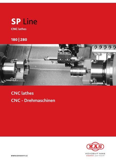
CNC lathes CNC - Drehmaschinen - Reiden Technik AG
CNC lathes CNC - Drehmaschinen - Reiden Technik AG
CNC lathes CNC - Drehmaschinen - Reiden Technik AG

Sie wollen auch ein ePaper? Erhöhen Sie die Reichweite Ihrer Titel.
YUMPU macht aus Druck-PDFs automatisch weboptimierte ePaper, die Google liebt.
SP Line<br />
<strong>CNC</strong> <strong>lathes</strong><br />
180 | 280<br />
<strong>CNC</strong> <strong>lathes</strong><br />
<strong>CNC</strong> - <strong>Drehmaschinen</strong><br />
www.kovosvit.cz
02 | SP 180/280 | <strong>CNC</strong> <strong>lathes</strong> | <strong>CNC</strong> - <strong>Drehmaschinen</strong><br />
Machine highlights // Hauptzüge der der Maschine<br />
� Two sizes of machines, identified by the name specifying the<br />
maximum machined diameter (180 mm or 280 mm), enable high<br />
performance machining including machining with the right spindle<br />
� Five technological variants of each machine size enable flexible<br />
choice of optimum machine variant, adapted to your technological<br />
requirements, from small-batch to specialized mass production<br />
� Solid machine base and bed guarantee high machine rigidity<br />
� Distortions of mechanical machine parts are verified by means of a<br />
numerical finite elements method – FEM<br />
� Dynamics and stability of axis motion are checked by means of<br />
advanced computation methods<br />
� Spindle units enable machining with the high performance<br />
� Synchronous integrated spindle motors provide the high dynamics of<br />
spindle functions and a powerful rotary axis C<br />
� Carriages of linear axes, the right headstock or tailstock body move<br />
on the rolling guideways and guarantee high accuracy of positioning<br />
and interpolated motion of axes and carriages<br />
� Rigidity of the upper carriage three-axis version is emphasized by<br />
virtual motion of axis Y which is composed of interpolation of real<br />
1<br />
axes X and Y’ making an angle of 30 degrees<br />
1<br />
� Programmable tailstock displacement reduces interventions of<br />
operating staff in machining process otherwise needed<br />
� Optional applicable state-of-the-art control systems by SINUMERIK<br />
840D sl, GE FANUC 0i and GE FANUC 30i guarantee excellent<br />
control properties and programmer comfort<br />
� The machines meet your expectations in terms of easy operation<br />
including integrated programming at workshop<br />
� Zwei Größen der Maschinen festgelegt im Namen mit dem maximalen<br />
Durchmesser des zu bearbeitenden Werkstückes (180 mm oder 280 mm)<br />
ermöglichen die hochproduktive Bearbeitung inklusive Bearbeitung an<br />
der rechten Spindel<br />
� Fünf technologische Varianten für jede Maschinengröße ermöglichen die<br />
Wahl, die auf Ihre technologischen Aufgaben optimal zugeschnitten ist,<br />
von der Klein- bis spezialisierte Großserienfertigung<br />
� Schwerer Maschinenrahmen und Bett gewähren die hohe<br />
Maschinensteifigkeit<br />
� Deformationen der mechanischen Maschinenteile werden mittels der<br />
numerischen Methode der Endelemente – FEM verifiziert<br />
� Dynamik und Stabilität der Bewegung der Achsen werden mittels der<br />
neuesten Berechnungsverfahren überprüft<br />
� Spindeleinheiten ermöglichen die hohe Zerspankraftleistung<br />
� Synchrone eingebaute Spindelmotoren bieten die hohe Dynamik der<br />
Spindelfunktionen und leistungsfähige Drehachse C<br />
� Supporte der linearen Achsen, rechter Spindelstock oder Reitstockkörper<br />
verstellen sich nach der Rollenführung und gewähren die hohe<br />
Genauigkeit der Positionierung und interpolierten Bewegung der Achsen<br />
der Supporte<br />
� Steifheit der dreiachsigen Ausführung des oberen Supportes wird durch<br />
Lösung mit virtueller Bewegung der Achse Y 1 gefördert, die durch<br />
Interpolation der realen, den Winkel von 30 Grad einschließenden<br />
Achsen X 1 und Y’ gestaltet ist<br />
� Programmierbare Bewegung des Reitstockes reduziert sonst nötige<br />
Bedienereingriffe in Bearbeitungsprozess<br />
� Wahlweise einsatzfähige modernste Steuersysteme SINUMERIK<br />
840D sl, GE FANUC 0i und GE FANUC 30i gewähren ausgezeichnete<br />
Regeleigenschaften und Programmierkomfort<br />
� Die Maschinen erfüllen Ihre Erwartungen bezüglich einfacher Bedienung<br />
sowie der Werkstattprogrammierung
<strong>CNC</strong> - <strong>Drehmaschinen</strong> | <strong>CNC</strong> <strong>lathes</strong> | SP 180/280 | 03
04 | SP 180/280 | <strong>CNC</strong> <strong>lathes</strong> | <strong>CNC</strong> - <strong>Drehmaschinen</strong><br />
Machine basic concept // Grundkonzeption der Maschine<br />
� Modular design of the machine allows compiling a number<br />
of technology variants. Machine design ensures high rigidity,<br />
high torque of the spindle, dynamics and high speed in all axes.<br />
By using the roller guideways, the high-precision machining is<br />
ensured on a long-term basis.<br />
� sp 180/280 sY<br />
5<br />
Variants of kinematic solution // Varianten der Kinematischen Lösung<br />
Machine type //<br />
Maschinentyp<br />
Main spindle units S 1 ; S 2 (counter spindle) //<br />
Hauptspindeleinheiten S 1 ; S 2 (Gegenspindel)<br />
1<br />
7<br />
9<br />
� Die Modularbauweise der Maschine ermöglicht es, ganze Reihe von<br />
technologischen Varianten zusammenzustellen. Die Konstruktion der<br />
Maschine sichert eine hohe Steifi gkeit, ein hohes Drehmoment der<br />
Spindel, Dynamik und hohe Geschwindigkeiten in den einzelnen Achsen<br />
ab. Durch die Anwendung der Rollenführung wird die Bearbeitung mit<br />
hoher Genauigkeit langzeitig sichergestellt.<br />
1 Machine foundation // Maschinenfundament 2 Bed // Bett 3 Slide - Y’-axis feed // Schlittenvorschub in der Y‘-Achse 4 Slide - Z -axis 1<br />
feed // Schlittenvorschub in der Z -Achse 5 Main spindle // Hauptspindel 6 Counter spindle // Gegenspindel 7 Tool head // Werkzeugkopf<br />
1<br />
8 Rolling guideways - X -axis // Rollenführung - X -Achse 9 Rolling guideways - Z -axis // Rollenführung - Z -Achse 10 Rolling guideways -<br />
1 1 S S<br />
Z -axis // Rollenführung - Z -Achse<br />
1 1<br />
8<br />
6<br />
3<br />
4<br />
Rotary axesof spindles //<br />
Drehachsen der Spindeln<br />
10<br />
2<br />
Tool spindle //<br />
Werkzeugspindel<br />
SP 180<br />
Spindle with belt drive A6 //<br />
Spindel mit dem Riemenantrieb A6<br />
S1 -- -- X , Z 1 1<br />
SP 180 MC<br />
SP 180 Y<br />
Motor spindle A5 // Motorspindel A5 S1 C1 S3 X , Z 1 1<br />
X , Y , Z 1 1 1<br />
SP 180 SMC<br />
SP 180 SY<br />
Motor spindle A5 // Motorspindel A5<br />
Motor spindle A5 // Motorspindel A5<br />
S1 S2 C1 C2 S3 X , Z , Z 1 1 S<br />
X , Y , Z , Z 1 1 1 S<br />
SP 280 Spindle with belt drive A6/A8 // Spindel mit dem Riemenantrieb A6/A8 S1 -- -- X , Z 1 1<br />
SP 280 MC<br />
SP 280 Y<br />
Motor spindle A6 // Motorspindel A6 S1 C1 S3 X , Z 1 1<br />
X , Y , Z 1 1 1<br />
SP 280 SMC<br />
SP 280 SY<br />
Motor spindle A6 // Motorspindel A6<br />
Motor spindle A5 // Motorspindel A5<br />
S1 S2 C1 C2 S3 X , Z , Z 1 1 S<br />
X , Y , Z , Z 1 1 1 S<br />
Linear axes of carriages //<br />
Lineare Achsen der Supporte
<strong>CNC</strong> - <strong>Drehmaschinen</strong> | <strong>CNC</strong> <strong>lathes</strong> | SP 180/280 | 05<br />
Definition of machine kinematic solution //<br />
Definition der Kinematischen Lösung der Maschinen<br />
S 1 C 1<br />
S 1 C 1<br />
S 1<br />
S 3<br />
S 3<br />
X 1<br />
X 1<br />
C 2 S 2<br />
Z 1<br />
Z 1<br />
X 1<br />
Z S<br />
Z 1<br />
X 1<br />
X 1<br />
X 1<br />
FEM model // FEM modell<br />
S 3<br />
S 1 C 1<br />
S 1 C 1<br />
Machine frame has been optimised regarding static rigidity and<br />
dynamic properties by means of a finite elements method.<br />
S 3<br />
Y 1<br />
X 1<br />
Y 1<br />
C 2 S 2<br />
X 1<br />
Z 1<br />
Z 1<br />
Z S<br />
X1 Y’ 1<br />
X1 Y’ 1<br />
Maschinentragteile werden bezüglich statischer Starrheit und<br />
dynamischer Eigenschaften mittels der Methode der Endelemente<br />
überprüft.<br />
Y 1<br />
Y 1
06 | SP 180/280 | <strong>CNC</strong> <strong>lathes</strong> | <strong>CNC</strong> - <strong>Drehmaschinen</strong><br />
Working space // Arbeitsraum<br />
Working space – construction of the machine with tailstock // Arbeitsraum – Ausführung der Maschine mit dem Reitstock<br />
Working space – construction of the machine with counter-spindle // Arbeitsraum – Ausführung der Maschine mit der Gegenspindel
<strong>CNC</strong> - <strong>Drehmaschinen</strong> | <strong>CNC</strong> <strong>lathes</strong> | SP 180/280 | 07<br />
Complete machining – high performance and productivity<br />
Komplette Bearbeitung – hohe Leistung und produktivität
08 | SP 180/280 | <strong>CNC</strong> <strong>lathes</strong> | <strong>CNC</strong> - <strong>Drehmaschinen</strong><br />
Demonstration technology for machine sp 180 sMC //<br />
Mustertechnologie für Drehmaschine sp180 sMC<br />
CYCLe tiMe // ZYKLusLAufZeit<br />
left spindle // linke Spindel 6,25 min<br />
right spindle // rechte Spindel 8,95 min<br />
total time // Gesamtzeit 15,20 min<br />
CuttiNG CoNDitioNs material steel 12050<br />
Roughning – cutting speed Vc = 200 m/min, feed f = 0,32/rev.<br />
Drilling – cutting speed Vc = 200 m/min., feed f = 0,15/rev.<br />
Finishing – cutting speed Vc = 260 m/min., feed f = 0,17/rev., Ra till 0,8<br />
Slots – cutting speed Vc = 100 - 120 m/min., feed f = 0,05-0,1/rev.<br />
Drilling NV Drill dia. 5mm<br />
S = 4000 rpm, f = 300m/min.<br />
sCHNittBeDiNGuNGeN Werkstoff 12050 (DiN C50, eN 2C45)<br />
Schruppen –<br />
Schnittgeschwindigkeit<br />
Vc=200m/min., Vorschub f=0,32/U.<br />
Bohren –<br />
Schnittgeschwindigkeit<br />
Fertigdrehen –<br />
Schnittgeschwindigkeit<br />
Einstechen –<br />
Schnittgeschwindigkeit<br />
Vc=200m/min., Vorschub f=0,15/U.<br />
Vc=260/min., Vorschub f=0,17/U., Ra bis 0,8<br />
Vc=100-120m/min., Vorschub f=0,05-0,1/U.<br />
Bohren angetr. Bohrer Ø 5 mm<br />
S =4000 U., f = 300m/min.<br />
1 turret — 1 spiNDLe // 1 Kopf — 1 spiNDeL<br />
CYCLe tiMe // ZYKLusLAufZeit<br />
1 turret — 2 spiNDLes // 1 Kopf — 2 spiNDeLN<br />
CYCLe tiMe // ZYKLusLAufZeit<br />
15,20 min<br />
22,80 min
installation drawing // Aufstellpläne<br />
<strong>CNC</strong> - <strong>Drehmaschinen</strong> | <strong>CNC</strong> <strong>lathes</strong> | SP 180/280 | 09
10 | SP 180/280 | <strong>CNC</strong> <strong>lathes</strong> | <strong>CNC</strong> - <strong>Drehmaschinen</strong><br />
technical Data // technische Daten<br />
teCHNiCAL DAtA // teCHNisCHe DAteN<br />
Working space // Arbeitsraum<br />
Axis travels // Verfahrwege der Achsen<br />
Swing dia. over bed // Umlaufdurchmesser über dem Bett mm<br />
Max. turning length // Max. Drehlänge mm<br />
Max. turning dia. // Max. Drehdurchmesser mm<br />
Max. bar stock capacity - spindle with belt drive // Max. Stangendurchlass -<br />
Spindel mit dem Riemenantrieb<br />
Max. bar stock capacity - motor spindle // max. Stangendurchlass -<br />
Motorspindel<br />
Axes X 1 / Z 1 // Achsen X 1 / Z 1<br />
Axis Y 1 // Achse Y 1<br />
The right headstock Zs // Rechter Spindelstock Zs mm<br />
Rapid traverse // Eilgang Axes X 1 / Z 1 // Achsen X 1 / Z 1 m.min -1<br />
Main spindle //<br />
Hauptspindel<br />
Belt drive //<br />
Riemenantrieb<br />
Motor spindle //<br />
Motorspindel<br />
Max. speed // Max. Drehzahl<br />
mm<br />
mm<br />
mm<br />
mm<br />
rpm // min -1<br />
rpm // min -1<br />
Counter spindle A5 // Gegenspindel A5 rpm // min -1<br />
Tool head // Werkzeugkopf<br />
Number of positions // Anzahl der Positionen -<br />
Hole dia. VDI // Aufnahme VDI mm<br />
Max. speed of tool spindle // Max. Werkzeugspindeldrehzahl rpm // min -1<br />
Tailstock // Reitstock Sleeve taper - MORSE // Innenkegel - MORSE -<br />
Spindle motor //<br />
Spindelmotor<br />
Belt drive //<br />
Riemenantrieb<br />
Motor spindle //<br />
Motorspindel<br />
Counter spindle //<br />
Gegenspindel<br />
Tool spindle //<br />
Werkzeugspindel<br />
Machine dimensions and weight //<br />
Abmessungen und Gewicht der Maschine<br />
Output S1 / S6 - 40% // Leistung S1 / S6 - 40% kW<br />
Max. torque S1 / S6 - 40% // max. Drehmoment S1 / S6 - 40% Nm<br />
Output S1 / S6 - 40% // Leistung S1 / S6 - 40% kW<br />
Max. torque S1 / S6 - 40% // max. Drehmoment S1 / S6 - 40% Nm<br />
Output S1/ S6 - 40% // Leistung S1 / S6 - 40% kW<br />
Max. torque S1 / S6 - 40% // Max. Drehmoment S1 / S6 - 40% Nm<br />
Output S3 - 40% // Leistung S3 - 40% kW<br />
Max. torque S3 - 40% // max. Drehmoment S3 - 40% Nm<br />
Length×width×heigth // Länge×Breite×Höhe mm<br />
Weight // Gewicht kg
sp 180<br />
<strong>CNC</strong> - <strong>Drehmaschinen</strong> | <strong>CNC</strong> <strong>lathes</strong> | SP 180/280 | 11<br />
sp 180<br />
sp 280<br />
sp 280<br />
MC Y sMC sY MC Y sMC sY<br />
530 530 530 530 530 570 570 570 570 570<br />
385 385 385 370 370 565 565 565 490 490<br />
180 180 180 180 180 280 280 280 280 280<br />
A6: Ø 63 - - - - A6: Ø 63 - - - -<br />
- A5: Ø 43 A5: Ø 43 A5: Ø 43 A5: Ø 43 - A6: Ø 61 A6: Ø 61 A6: Ø 61 A6: Ø 61<br />
165 / 480 165 / 480 165 / 480 113 / 480 113 / 480 245 / 640 245 / 640 245 / 640 194 / 640 194 / 640<br />
- - ±45 - ±45 - - ±50 - ±50<br />
- - - 725 725 - - - 725 725<br />
30 / 30 30 / 30 30 / 30 30 / 30 30 / 30 30 / 30 30 / 30 30 / 30 30 / 30 30 / 30<br />
A6: 4 700 - - - - A6: 4 700 - - - -<br />
- A5: 6 000 A5: 6 000 A5: 6 000 A5: 6 000 - A6: 4 700 A6: 4 700 A6: 4 700 A6: 4 700<br />
- - - A5: 6 000 A5: 6 000 - - - A5: 6 000 A5: 6 000<br />
12 12 12 12 12 12 12 12 12 12<br />
30 30 30 30 30 40 40 40 40 40<br />
- 5 000 5 000 5 000 5 000 - 4 000 4 000 4 000 4 000<br />
Mo 5 Mo 5 Mo 5 - - Mo 5 Mo 5 Mo 5 - -<br />
A6: 20 / 30 - - - - A6: 22 / 33 - - - -<br />
A6: 152 / 229 - - - - A6: 273 / 410 - - - -<br />
- 16,8 / 22 16,8 / 22 16,8 / 22 16,8 / 22 - 20,9 / 27 20,9 / 27 20,9 / 27 20,9 / 27<br />
- 100 / 130 100 / 130 100 / 130 100 / 130 - 200 / 257 200 / 257 200 / 257 200 / 257<br />
- - - 7,5 / 9 7,5 / 9 - - - 7,5 / 9 7,5 / 9<br />
- - - 48 / 57 48 / 57 - - - 48 / 57 48 / 57<br />
- 6 6 6 6 - 8 8 8 8<br />
- 28 28 28 28 - 40 40 40 40<br />
3 875 × 2 122 × 2 345 3 875 × 2 122 × 2 345<br />
7 000 7 300 7 500 7 600 7 700 7 200 7 500 7 700 7 800 7 900<br />
The machine conforms to // Die Maschine ist konform mit<br />
In view of continuous machine development and innovation, specifi cations in this advertising material are subject to change without notice. //<br />
Bei der Berücksichtigung der fortlaufenden Entwicklung und Innovation der Maschinen sind die Angaben in diesem Werbematerial nicht verbindlich.
12 | SP 180/280 | <strong>CNC</strong> <strong>lathes</strong> | <strong>CNC</strong> - <strong>Drehmaschinen</strong><br />
Accessories // Zubehör<br />
stANDArD ACCessories // NorMALZuBeHÖr sp 180 sp 280<br />
Through clamping cylinder (the left headstock) // Hohlspannzylinder (linker Spindelstock) � �<br />
Solid clamping cylinder (the right headstock) // Vollspannzylinder (rechter Spindelstock) � �<br />
The left and right spindle locking (motor spindle) // Klemmung der linken und rechten Spindel (Motorspindel) � �<br />
Direct measuring in axis X 1 // Direkte Wegmessung in der Achse X 1 � �<br />
Absolute measuring of linear axes // Absolutmessung der linearen Achsen � �<br />
Tool cooling - 7 bar // Werkzeugkühlung - 7 bar � �<br />
Tailstock incl. connection // Reitstock inkl. Anschlusses � �<br />
Machine lighting // Maschinenbeleuchtung � �<br />
Tool kit // Bedienwerkzeug � �<br />
speCiAL ACCessories // soNDerZuBeHÖr<br />
Chucks A5, A6, A8 // Spannfutter A5, A6, A8 � �<br />
Special fixtures // Spezielle Werkzeugspanner � �<br />
Tool holders // Werkzeughalter � �<br />
High-pressure tool cooling - 17 bar with filtration // Hochdruckkühlung der Werkzeuge - 17 bar mit Filtration � �<br />
The left spindle locking (belt drive) // Klemmung der linken Spindel (Riemenantrieb) � �<br />
Fixture blowing – the right headstock // Beblasung des Werkzeugspanners – rechter Spindelstock � �<br />
Ejector of parts in the right headstock // Auswerfer des Werkstückes in dem rechten Spindelstock � �<br />
Parts catcher // Werkstückentnahmeeinrichtung � �<br />
Bar guide // Stangenführung � �<br />
Adaptation for bar feeder // Anpassung für Stangenzuführung � �<br />
Bar feeder // Stangenzuführung � �<br />
Manual rinsing // Handspülen � �<br />
Vapour exhaustion from working space // Dampfabsaugung aus dem Arbeitsraum � �<br />
Automatic tool check // Automatische Werkzeugüberwachung � �<br />
Remote diagnostics // On-Line-Diagnostik � �<br />
Chip conveyor incl. connection // Späneförderer inkl. Anschlusses � �<br />
Chip container with tank // Spänebecken mit dem Behälter � �<br />
Automatic working space guard shifting // Automatische Schiebetür des Arbeitsraumes � �<br />
Machine state signalling (beacon) // Maschinenzustandanzeige (Blinkfeuer) � �<br />
Lifting device // Hebevorrichtung � �
industry and applications //<br />
industriebereiche und Anwendung<br />
Automotive / Agricultural Machines //<br />
Automotive / Landwirtschaftliche Maschinen<br />
� Connectors, Flanges, Shafts<br />
� Kupplungen, Flansche, Wellen<br />
Common Mechanical Engineering, Varied parts production //<br />
Allgemeiner Maschinenbau, Bearbeitung von verschiedenen Werkstücken<br />
� Rotary parts, machining from bar diameter 63mm<br />
� Drehteile, Stangenbearbeitung bis 63 mm Drm.<br />
Textile Industry //<br />
Textilindustrie<br />
� Components of textile machine<br />
� Bauteile der Textilmaschinen<br />
Printing Industry //<br />
Polygrafische Industrie<br />
� Components of printing machines<br />
� Bauteile der Druckmaschinen<br />
<strong>CNC</strong> - <strong>Drehmaschinen</strong> | <strong>CNC</strong> <strong>lathes</strong> | SP 180/280 | 13<br />
Electrotechnical industry //<br />
Elektrotechnische Industrie<br />
� Electric motor shafts, rotors<br />
� Wellen der Elektromotore, Rotoren<br />
Food Processing Industry //<br />
Nahrungsmittelindustrie<br />
� Komponenten und Bauteile für Verarbeitungslinien<br />
� Components of Food processing machines and lines
14 | SP 180/280 | <strong>CNC</strong> <strong>lathes</strong> | <strong>CNC</strong> - <strong>Drehmaschinen</strong><br />
remote diagnostics � complementary service that saves your money<br />
ferndiagnose � zusätzliche Dienstleistung, die ihnen Geld spart<br />
� Fastest technical and technological service for the customer<br />
� Immediate “on-Line” contact with the customer’s machine<br />
� Inexpensive and reliable technical solution<br />
� Experienced team of diagnosticians and application engineers - technologists<br />
Remote diagnostics are the analysis of the machine’s condition via communication software<br />
by a diagnostician. Using the communication software, the screen and the dialogue menu of<br />
the control system are remotely accessible via Internet. The actual communication software<br />
does not include any diagnostic tools. The service technician only remotely uses the internal<br />
diagnostic capabilities of the control system. The screen and the dialogue menu of the <strong>CNC</strong><br />
are accessible from the service technician’s computer at any distance. The technician not<br />
only monitors the current condition of the machine via his screen, but using the keyboard<br />
of his computer controls the <strong>CNC</strong> menu, transfers basically all data in both directions, and<br />
using the CHAT function communicates with the operator. During machine failure analysis,<br />
the technician utilises all diagnostic functions integrated in the <strong>CNC</strong>.<br />
The goal of Remote diagnostics is to shorten the downtime of the machine by precisely<br />
targeting the subsequent servicing activity. This brings especially a reduction of customer’s<br />
losses arising from the machine downtime.<br />
� Schnellste technische und technologische Dienstleistung für den Kunden<br />
� Unmittelbarer Kontakt mit der Maschine des Kunden “online”<br />
� Preiswerte und zuverlässige technische Lösung<br />
� Erfahrenes Team von Diagnostikern und Applikationsingenieuren - Technologen<br />
Die Ferndiagnostik ist eine Analyse des Maschinenstatus mithilfe der<br />
Kommunikationssoftware durch den Diagnostiker. Mit der Kommunikationssoftware<br />
wird mithilfe des Internets der Fernzugriff zum Bildschirmbild und zum Dialogmenü<br />
des Steuersystems möglich gemacht. Die Kommunikationssoftware selbst beinhaltet<br />
keine Diagnostikinstrumente. Der Kundendiensttechniker nutzt nur die internen<br />
Ferndiagnostikmöglichkeiten des Steuersystems. Im Rechner des Kundendiensttechnikers<br />
wird das Bildschirmbild sowie das <strong>CNC</strong>-Dialogmenü auf beliebige Entfernung zugänglich<br />
gemacht. Der <strong>Technik</strong>er überwacht nicht nur den aktuellen Status der Maschine über<br />
deren Bildschirmbild, sondern betätigt mithilfe der Taste seines Rechners das <strong>CNC</strong>- Menü,<br />
überträgt zweiseitig praktisch sämtliche Daten und führt mithilfe der CHAT-Funktion den<br />
Dialog mit dem Bedienungspersonal. Bei der Analyse eines Fehlers der Maschine nutzt der<br />
<strong>Technik</strong>er alle im <strong>CNC</strong> integrierten Diagnostikfunktionen.<br />
Das Ziel der Ferndiagnostik ist die Betriebsunterbrechung der Maschine dadurch zu<br />
kürzen, indem der anschließende Kundendiensttätigkeit bereits genau gezielt ist. Das<br />
bringt vor allem eine Reduzierung der Verluste des Kunden mit sich, die durch die<br />
Betriebsunterbrechung der Maschine entstehen.<br />
LAn network<br />
KOVOSVit MAS<br />
internet<br />
VPn tUneL PPtP type<br />
Customer's LAn<br />
network
MAs MACHiNe MoNitor<br />
� tool for increasing the productivity of your operation!<br />
� instrument zur steigerung der produktivität ihres Betriebsablaufs!<br />
SP 280 Y<br />
<strong>CNC</strong> - <strong>Drehmaschinen</strong> | <strong>CNC</strong> <strong>lathes</strong> | SP 180/280 | 15<br />
MAS MACHINE MONITOR is a software product that allows the customer to monitor the<br />
time utilisation of machine during the shift online or allows to view the operating status<br />
history and to subsequently take measures in production and logistics. All this is possible in<br />
the visualisation program that is installed in the customer’s PC.<br />
MAS MACHINE MONITOR means an arguable leap increase of your operation’s<br />
productivity = Your pAtH to CoMpetitiVeNess eNHANCeMeNt tHANKs to MAs!<br />
Basic functions of the MAs MACHiNe MoNitor:<br />
� Monitoring of utilisation of any number of machines, possibility of machine classifying<br />
into groups (workplaces)<br />
� Online display of machine status or browsing through utilisation history<br />
� Number of made pieces, display of power circuit start interval – electricity saving<br />
measures<br />
� Summary statistics for individual machines<br />
� Important information for company management and production control<br />
An option of the MAs MACHiNe MoNitor is the MAs GsM MoNitor - monitoring<br />
of selected machine conditions via mobile phone operator network at selected phone<br />
numbers in the form of an sMs message. the employee can thus immediately react to<br />
an event even if he is not present near the machine at the moment.<br />
Be independently and factually informed about the course of your jobs directly from<br />
the machine even during your physical absence from the company!<br />
GsM MoNitoriNG - function of the GsM MoDuLe:<br />
Via the touch panel, it is possible to define up to 5 phone numbers that can be used for<br />
monitoring and controlling of the machine.<br />
SMS messages about machine condition changes are then sent to the entered phone<br />
numbers.<br />
The current condition of the machine can also be queried by sending an SMS reading<br />
“STATUS”.<br />
The SMS can optionally be sent also upon meeting a certain condition (e.g. making a certain<br />
number of pieces etc.)<br />
Via the SMS from some predefined number, up to 2 user signals can be controlled. The<br />
machine’s behaviour can thus be controlled remotely (e.g. machine shutdown after<br />
completing the current part, production change to another part type, etc.).<br />
MAS MACHINE MONITOR ist ein Software-Produkt, das dem Kunden ermöglicht die zeitliche Auslastung der Maschine während der Schicht online<br />
zu überwachen bzw. ermöglicht Einsicht in die Betriebsstatushistorie zu nehmen und somit anschließend Maßnahmen in der Produktion und Logistik<br />
zu treffen. Das alles ist im Visualisierungsprogramm möglich, dass im PC des Kunden installiert wird.<br />
MAS MACHINE MONITOR bedeutet eine nachweisbare, sprungartige steigerung der produktivität ihres Betriebsablaufs =<br />
iHr WeG Zur erHÖHuNG Der KoNKurreNZfÄHiGKeit DANK MAs!<br />
Grundfunktionen von MAs MACHiNe MoNitor:<br />
� Überwachung der Auslastung einer beliebigen Anzahl von Maschinen, Möglichkeit der Zuordnung von Maschinen in Gruppen (Arbeitsplätze)<br />
� Anzeige des Maschinenstatus online bzw. Durchgehen der Auslastung in der Historie<br />
� Hergestellte Stückzahl, Anzeige des Einschaltintervalls der Kraftstromkreise – Maßnahme zur Einsparung elektrischer Energie<br />
� Zusammenfassende Statistiken für die einzelnen Maschinen<br />
� Wichtige Informationen für das Management der Firma sowie die Produktionsleitung<br />
Die option von MAs MACHiNe MoNitor ist der MAs GsM MoNitor – die Überwachung des gewählten Status der Maschine mithilfe des<br />
Netzes des Mobiltelefonoperators für auserlesene Telefonnummern in Form einer SMS-Nachricht. Der Mitarbeiter kann somit sofort auf das Ereignis<br />
reagieren, auch wenn er gerade nicht an der Maschine anwesend ist.<br />
Seien Sie unabhängig und real über den Ablauf Ihrer Aufträge direkt aus der Maschine auch während Ihrer physischen Abwesenheit in der<br />
Firma informiert!<br />
GsM MoNitoriNG – funktion des GsM MoDuLs:<br />
Mithilfe des Tastfelds können bis zu 5 Telefonnummern definiert werden, die zur Überwachung und Steuerung der Maschine benutzt werden können.<br />
An die eingegebenen Telefonnummern werden dann SMS-Nachrichten über Änderungen des Status der Maschine versendet.<br />
Nach dem aktuellen Status der Maschine kann man auch durch die Versendung einer SMS-Nachricht in Form von „STATUS“ fragen.<br />
Eine SMS kann man wahlweise auch bei der Erfüllung einer bestimmten Bedingung versenden (z.B. Anfertigung einer bestimmten Stückzahl u.Ä.).<br />
Mithilfe einer SMS von einer der vordefinierten Nummern aus können bis zu 2 Anwendungssignale bedient werden. Auf diese Weise kann das<br />
Verhalten der Maschine ferngesteuert werden (zum Beispiel die Außerbetriebsetzung der Maschine nach der Fertigstellung des aktuellen Werkstücks,<br />
der Wechsel der Fertigung zu einem anderen Werkstücktyp u.Ä.).
Vertrieb Schweiz und Service durch:<br />
Distribution Suisse et sérvice par:<br />
<strong>Reiden</strong> <strong>Technik</strong> <strong>AG</strong><br />
Werkzeugmaschinen Tel. 062 749 20 20<br />
Werkstrasse 2 info@reiden.com<br />
CH-6260 <strong>Reiden</strong> www.reiden.com