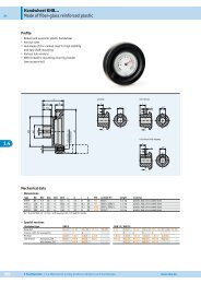
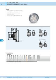
WK02/1 - SIKO Products USA
WK02/1 - SIKO Products USA
WK02/1 - SIKO Products USA

Erfolgreiche ePaper selbst erstellen
Machen Sie aus Ihren PDF Publikationen ein blätterbares Flipbook mit unserer einzigartigen Google optimierten e-Paper Software.
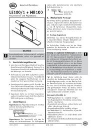
DEUTSCH<br />
1. Gewährleistungshinweise<br />
•<br />
•<br />
•<br />
•<br />
•<br />
Lesen Sie vor der Montage und der Inbetriebnahme<br />
dieses Dokument sorgfältig durch. Beachten Sie zu<br />
Ihrer eigenen Sicherheit und der Betriebssicherheit<br />
alle Warnungen und Hinweise.<br />
Ihr Produkt hat unser Werk in geprüftem und betriebsbereitem<br />
Zustand verlassen. Für den Betrieb<br />
gelten die angegeben Spezifikationen und die<br />
Angaben auf dem Typenschild als Bedingung.<br />
Garantieansprüche gelten nur für Produkte der<br />
Firma <strong>SIKO</strong> GmbH. Bei dem Einsatz in Verbindung<br />
mit Fremdprodukten besteht für das Gesamtsystem<br />
kein Garantieanspruch.<br />
Bei Störungen oder Geräteausfällen sollten Sie<br />
niemals versuchen, die Geräte selbst zu öffnen.<br />
Ansonsten setzen Sie sich der Gefahr aus, mit<br />
Teilen, die unter hoher Spannung stehen, in<br />
Kontakt zu geraten.<br />
Reparaturen dürfen nur im Werk vorgenommen<br />
werden. Für weitere Fragen steht Ihnen die Firma<br />
<strong>SIKO</strong> GmbH gerne zur Verfügung.<br />
2. Identifikation<br />
Das Typenschild zeigt den Gerätetyp mit Variantennummer.<br />
Die Lieferpapiere ordnen jeder Variantennummer<br />
eine detaillierte Bestellbezeichnung zu.<br />
z.B. <strong>WK02</strong>/1-0023<br />
Benutzerinformation<br />
<strong>WK02</strong>/1<br />
Winkelkodierer Singleturn<br />
Varianten-Nr.<br />
Geräte-Typ<br />
3. Mechanische Montage<br />
Die Montage darf nur gemäß der angegebenen IP-<br />
Schutzart vorgenommen werden. Das System muss<br />
ggfs. zusätzlich gegen schädliche Umwelteinflüsse,<br />
wie z.B. Spritzwasser, Staub, Schläge, Temperatur<br />
geschützt werden.<br />
Achtung! Radialdichtringe sind Verschleißteile!<br />
Die Schutzart ist deshalb abhängig von Lebensdauer<br />
und Zustand der Dichtringe.<br />
3.1 Montagehinweise<br />
Gehen Sie sorgfältig mit dem Geber um. Es handelt<br />
sich um ein Präzisionsmessgerät. Folgende Punkte<br />
führen unverzüglich zum Verfall der Garantie:<br />
Zerlegen oder Öffnen des Gebers (soweit dies<br />
nicht in dieser Benutzerinformation beschrieben<br />
wird).<br />
Schläge auf den Geber oder die Welle, da dadurch<br />
interne Elemente wie z.B. die optische Kodescheibe<br />
beschädigt werden können.<br />
Mechanische Bearbeitung der Welle, des Flansches<br />
oder Gehäuses (Bohren, Fräsen, usw.). Hierdurch<br />
kann es zu schweren Beschädigungen der inneren<br />
Teile des Gebers kommen.<br />
Unzulässige axiale oder radiale Belastung der<br />
Welle.<br />
• Unsachgemäße Befestigung des Gebers.<br />
Abb. 1: Montagehinweise<br />
4. Elektrischer Anschluss<br />
<strong>WK02</strong>/1 Datum 02.04.2009 Art.Nr. 78276 Änd. Stand 108/09 1<br />
•<br />
•<br />
•<br />
•<br />
•<br />
•<br />
•<br />
Steckverbindungen dürfen nicht unter Spannung<br />
gesteckt oder abgezogen werden.<br />
Alle Verdrahtungsarbeiten dürfen nur spannungslos<br />
erfolgen.<br />
Vor dem Einschalten sind alle Leitungsanschlüsse<br />
und Steckverbindungen zu überprüfen.<br />
•<br />
Für Geber mit Parallelausgang: nicht benutzte<br />
Signalleitungen sind über einen Widerstand (z.B.<br />
R=10k) gegen Masse zu schalten.
•<br />
Die Betriebsspannung muss gemeinsam mit der<br />
Folgeelektronik (z.B. Steuerung) eingeschaltet<br />
werden.<br />
• Litzen sind mit Aderendhülsen zu versehen.<br />
•<br />
Die Schnittstellensignale DÜA und DÜB sind bei<br />
Nichtgebrauch an GND anzuschließen.<br />
Hinweise zur Störsicherheit<br />
Alle Anschlüsse sind gegen äußere Störeinflüsse<br />
geschützt. Der Einsatzort ist aber so zu wählen,<br />
dass induktive oder kapazitive Störungen nicht<br />
auf den Geber oder dessen Anschlussleitungen<br />
einwirken können! Durch geeignete Kabelführung<br />
und Verdrahtung können Störeinflüsse (z.B.<br />
von Schaltnetzteilen, Motoren, getakteten Reglern<br />
oder Schützen) vermindert werden.<br />
Erforderliche Maßnahmen<br />
•<br />
•<br />
Nur geschirmtes Kabel verwenden. Den Kabelschirm<br />
beidseitig auflegen. Litzenquerschnitt der<br />
Leitungen min. 0,14 mm²; max. 0,5 mm².<br />
Die Verdrahtung von Abschirmung und Masse<br />
(0V) muss sternförmig und großflächig erfolgen.<br />
Der Anschluss der Abschirmung an den Potentialausgleich<br />
muss großflächig (niederimpedant)<br />
erfolgen.<br />
• Kabelschirm beidseitig auflegen.<br />
•<br />
•<br />
Das System muss in möglichst großem Abstand von<br />
Leitungen eingebaut werden, die mit Störungen<br />
belastet sind; ggfs. sind zusätzliche Maßnahmen<br />
wie Schirmbleche oder metallisierte Gehäuse<br />
vorzusehen. Leitungsführungen parallel zu Energieleitungen<br />
vermeiden.<br />
Schützspulen müssen mit Funkenlöschgliedern<br />
beschaltet sein.<br />
Spannungsversorgung<br />
Die Spannungswerte ist u.a. den Lieferpapieren<br />
oder dem Typenschild zu entnehmen.<br />
4.1 Schnittstellen<br />
z.B.: 24VDC±20%<br />
Parallele Schnittstelle P1 (Push-Pull)<br />
Der Positionswert steht in paralleler Form an den<br />
Ausgängen des <strong>WK02</strong>/1 wahlweise in Binärer Form<br />
oder als Gray-codiertem Wert an. Die Einstellung<br />
kann ab Werk erfolgen oder über die Parametrierschnittstelle<br />
eingestellt werden. Weitere Informationen<br />
zum Funktionsprinzip der parallelen<br />
Schnittstelle sind dem <strong>SIKO</strong>-Prospekt "Winkelcodierer"<br />
zu entnehmen.<br />
Serielle Schnittstellen<br />
Bei SSI bzw. Feldbussystem <strong>SIKO</strong>NETZ kann die<br />
Auflösung des Gebers über die Programmierschnittstelle<br />
(siehe Kapitel 6) entsprechend umkonfiguriert<br />
werden.<br />
Bei InterBus-S oder Profibus-DP muss die Konfiguration<br />
der Geberauflösung bei <strong>SIKO</strong> erfolgen oder<br />
die Nachfolgeelektronik entsprechend programmiert<br />
werden.<br />
Serielle Schnittstelle S6/04 (SSI)<br />
Weitere Informationen zum Funktionsprinzip der<br />
SSI-Schnittstelle sind dem <strong>SIKO</strong>-Prospekt "Winkelcodierer"<br />
zu entnehmen.<br />
Serielle Schnittstelle S3/01, S3/05 (<strong>SIKO</strong>NETZ)<br />
Die <strong>SIKO</strong>NETZ-Schnittstelle erlaubt den Betrieb<br />
des Winkelcodierers in einem Bus-System. Die<br />
Beschreibung der Hardware- und Software-Funktionen<br />
sind umfangreich und nicht in dieser Benutzerinformation<br />
enthalten. Bitte ziehen Sie für<br />
alle die <strong>SIKO</strong>NETZ-Schnittstelle betreffenden Fragen<br />
die <strong>SIKO</strong>NETZ-Dokumentation heran, in der<br />
ausführliche Informationen über Anwendung und<br />
Programmierung enthalten sind.<br />
Serielle Schnittstelle IB3 (Interbus-S)<br />
Der Feldbus INTERBUS-S ist als Installationsfernbus<br />
aufgebaut, d.h. über das Buskabel wird der<br />
Geber mit Spannung versorgt. Die InterBus-S-<br />
Schnittstelle wird ausführlich in den Unterlagen<br />
der Fa. PHOENIX, Blomberg beschrieben.<br />
Hinweis Busabschluss: Eine Brücke im Stecker der<br />
weiterführenden Busleitung von Pin 9 (RBST) nach<br />
Pin 5 (GND) zeigt dem auf der Interbus-Karte vorhandenen<br />
Protokoll-Chip an, dass die Busleitung<br />
auf einen weiteren Interbus-S-Teilnehmer führt.<br />
Hinweis Identifikation:<br />
• Identnummer: 37 (= 55 )<br />
Hex DEZ<br />
•<br />
Datenwortbreite: 2 Worte (= 4 Bytes)<br />
Serielle Schnittstelle PB (Profibus-DP)<br />
Hinweis Busabschluss: Bei Busbetrieb muss beim<br />
letzten Gerät am Bus (am Ende der Busleitung)<br />
ein Busabschluss eingefügt werden. Dieser Busabschluss,<br />
in Form eines Steckers, kann als Zubehör<br />
über die Firma <strong>SIKO</strong> unter der Bezeichnung BAS-<br />
0002 bezogen werden.<br />
5. Anschlussarten<br />
Achtung! Die Signale 0V und GND sind nicht<br />
identisch und dürfen nicht miteinander verbunden<br />
werden!<br />
2 <strong>WK02</strong>/1 Datum 02.04.2009 Art.Nr. 78276 Änd. Stand 108/09
5.1 Anschlussart E1<br />
Parallele Schnittstelle P1 (Push-Pull)<br />
Kabelfarbe Signal<br />
rot D0<br />
blau D1<br />
gelb D2<br />
grün D3<br />
weiß D4<br />
rosa D5<br />
schwarz D6<br />
violett D7<br />
braungrün D8<br />
weißgelb D9<br />
gelbbraun D10<br />
grauweiß D11<br />
graubraun D12<br />
weißrot DÜA (Schnittstelle)<br />
weißblau DÜB (Schnittstelle)<br />
weißschwarz GND (Schnittstelle)<br />
braun +UB (Versorgung)<br />
grau OV (Versorgung)<br />
5.2 Anschlussart E2<br />
Serielle Schnittstelle S6/04 (SSI) 9-pol.<br />
Ansichtseite = Steckseite<br />
Stiftkontakt Geräteseite<br />
Ansichtseite = Lötseite<br />
Buchsenkontakt Gegenstecker<br />
Ansichtseite = Steckseite<br />
Stiftkontakt Geräteseite<br />
Ansichtseite = Lötseite<br />
Buchsenkontakt Gegenstecker<br />
PIN Kabelfarbe Signal<br />
1 rosa Daten-<br />
2 blau Daten+<br />
3 rot Takt-<br />
4 schwarz Takt+<br />
5 braun +UB (Versorgung)<br />
6 weiß GND (Schnittstelle)<br />
7 gelb DÜA (Schnittstelle)<br />
8 grün DÜB (Schnittstelle)<br />
9 grau 0V (Versorgung)<br />
5.3 Anschlussart E4<br />
Serielle Schnittstelle S3/01; S3/05 (<strong>SIKO</strong>NETZ)<br />
7-pol.<br />
Ansichtseite = Steckseite<br />
Buchsenkontakt Geräteseite<br />
Ansichtseite = Lötseite<br />
Stiftkontakt Gegenstecker<br />
PIN Kabelfarbe Signal<br />
1 weiß GND (Schnittstelle)<br />
2 - - - - - -<br />
3 blau DÜB (Schnittstelle)<br />
4 grün DÜA (Schnittstelle)<br />
5 braun +UB (Versorgung)<br />
6 grau 0V (Versorgung)<br />
7 - - - - - -<br />
5.4 Anschlussart E6<br />
Parallele Schnittstelle P1 (Push-Pull) 26-pol.<br />
Ansichtseite = Steckseite<br />
Stiftkontakt Geräteseite<br />
Ansichtseite = Lötseite<br />
Buchsenkontakt Gegenstecker<br />
PIN Kabelfarbe Signal<br />
1 rot D0<br />
2 blau D1<br />
3 gelb D2<br />
4 grün D3<br />
5 weiß D4<br />
6 rosa D5<br />
7 schwarz D6<br />
8 violett D7<br />
9 braungrün D8<br />
10 weißgelb D9<br />
11 gelbbraun D10<br />
12 grauweiß D11<br />
13 graubraun D12<br />
14 - 20 - - - - - -<br />
21 weißrot DÜA (Schnittstelle)<br />
22 weißblau DÜB (Schnittstelle)<br />
23 weißschwarz GND (Schnittstelle)<br />
24 braun +UB (Versorgung)<br />
25 grau OV (Versorgung)<br />
26 - - - - - -<br />
5.5 Anschlussart E7<br />
Serielle Schnittstelle IB3 (Interbus-S) 9-pol.<br />
ankommender Fernbus (Stift)<br />
Ansichtseite = Steckseite<br />
Stiftkontakt Geräteseite<br />
Ansichtseite = Lötseite<br />
Buchsenkontakt Gegenstecker<br />
<strong>WK02</strong>/1 Datum 02.04.2009 Art.Nr. 78276 Änd. Stand 108/09 3
PIN Kabelfarbe Signal<br />
1 gelb D0<br />
2 grün D0<br />
3 grau DI<br />
4 rosa DI<br />
5 braun GND (Schnittstelle)<br />
6 grüngelb PE<br />
7 rot +UB (Versorgung)<br />
8 blau 0V (Versorgung)<br />
9 - - - - - -<br />
weiterführender Fernbus (Buchse)<br />
Ansichtseite = Steckseite<br />
Buchsenkontakt Geräteseite<br />
Ansichtseite = Lötseite<br />
Stiftkontakt Gegenstecker<br />
PIN Kabelfarbe Signal<br />
1 gelb D0<br />
2 grün D0<br />
3 grau DI<br />
4 rosa DI<br />
5 braun GND (Schnittstelle)<br />
6 grüngelb PE<br />
7 rot +UB (Versorgung)<br />
8 blau 0V (Versorgung)<br />
9 - - - RBST<br />
Serielle Schnittstelle PB (Profibus-DP)<br />
PIN Signal<br />
1 DGND (2M)<br />
2 RXD/TXD-N (A-Line)<br />
3 - - -<br />
4 RXD/TXD-P (B-Line)<br />
5 - - -<br />
6 VP (2P5)<br />
7 +EV (+24V)<br />
8 0V<br />
9 - - -<br />
10 - - -<br />
11 - - -<br />
12 RTS<br />
Anschlussart E4<br />
Ansichtseite = Steckseite<br />
Buchsenkontakt Geräteseite<br />
Anschluss mit Kupplungsstecker und Kupplungsdose<br />
der Fa. Binder Serie 423<br />
1.<br />
2.<br />
3.<br />
4.<br />
5.<br />
6.<br />
Pos. 6...10 über Kabelmantel schieben.<br />
Kabel abisolieren.<br />
Schirm umlegen.<br />
Pos. 5 auf Litzen schieben.<br />
Kabel an Pos. 3 löten (entspr. Anschlussplan).<br />
Abstandshülse Pos. 4 aufweiten und über Lit-<br />
zen stülpen, zusammendrücken und auf Pos. 3<br />
stecken. Schlitz und Nut (Pos. 3 und 4) müssen<br />
deckungsgleich sein.<br />
Pos. 6 an Pos. 5 drücken, überstehenden Schirm<br />
abschneiden.<br />
Pos. 2 und 7 aufschieben und mittels Montagewerkzeug<br />
Pos. 11 verschrauben.<br />
Pos. 8 in Pos. 9 stecken, beides in Pos. 7<br />
schieben.<br />
10. Pos. 10 mit Pos. 7 verschrauben.<br />
11. Pos. 1 in Pos. 2 schieben.<br />
Stiftteil<br />
Buchsenteil<br />
4 <strong>WK02</strong>/1 Datum 02.04.2009 Art.Nr. 78276 Änd. Stand 108/09<br />
7.<br />
8.<br />
9.<br />
Schirm<br />
Anschlussart E2 und E7<br />
1.<br />
2.<br />
3.<br />
4.<br />
5.<br />
6.<br />
7.<br />
Schirm<br />
Adapter Pos. 1 und Dichtelement Pos. 2 auf das<br />
Kabel schieben.<br />
Kabel-Außenmantel auf 22mm abisolieren.<br />
Schirmgeflecht 90° hochstellen. Schirmhülse<br />
Pos. 3 über die Folie bzw. Baumwollgeflecht,<br />
jedoch under das Schirmgeflecht schieben;<br />
Schirmgeflecht bündig mit Außendurchmesser<br />
Schirmhülse Pos. 3 schneiden.<br />
Folie, Füller und innere Isolierung abschneiden,<br />
Litzen auf 3,5mm abisolieren, verdrillen und<br />
verzinnen.<br />
Litzen an Kontakteinsatz Pos. 4 anlöten. Rändel<br />
Pos. 7 über Einsatzhülse Pos. 6 schieben. Distanzhülse<br />
Pos. 5 zwischen Einsatz Pos. 4 und<br />
Schirmhälse Pos. 3 einfügen und schließen.<br />
Einsatz Pos. 4, Distanzhülse Pos. 5 und Schirmhülse<br />
Pos. 3 in Einsatzhülse Pos. 6 einführen.<br />
Hierbei ist zu beachten, dass die gewünschte<br />
Codiernut des Einsatzes Pos. 4 in den Codiersteg<br />
eingeführt wird.<br />
Einsatzhülse Pos. 6 mit Hilfe des Montageschlüssels<br />
(Pos. 8 oder Gegenstecker am Geber), mit<br />
Adapter Pos. 1 auf anschlag verschrauben.
Wichtig! Axialspiel zwischen Rändelmutter Pos. 7<br />
und Adapter Pos. 1 max. 0,2mm.<br />
6. Programmierung<br />
Der Geber lässt sich bei den Ausführungen P1<br />
(Parallel / Push-Pull), S6/04 (SSI) und S3/01 +<br />
S3/05 (<strong>SIKO</strong>NETZ) so programmieren, dass seine<br />
Parameter auf die Anforderungen der Anwendung<br />
oder Nachfolgeelektronik angepasst werden können.<br />
Dadurch kann z.B. eingestellt werden, ob die<br />
Ausgabe des Codewertes in Gray- oder Binärwerten<br />
erfolgen soll. Für die Programmierung steht<br />
ein spezieller Befehlssatz zur Verfügung.<br />
Bei InterBus-S oder Profibus-DP muss die Konfiguration<br />
des Gebers bei <strong>SIKO</strong> erfolgen oder die<br />
Nachfolgeelektronik entsprechend programmiert<br />
werden.<br />
Programmierschnittstelle RS485<br />
Die Anschlüsse der Programmierschnittstelle (DÜA,<br />
DÜB und GND) sind am Stecker oder als Kabelenden<br />
verfügbar (siehe Kapitel 5).<br />
Achtung! Zur Programmierung von Gebern mit<br />
<strong>SIKO</strong>NETZ-Datenschnittstelle muss die Busadresse<br />
durch Betätigung des Kodierschalters auf 0 gesetzt<br />
werden (s. Kapitel 9).<br />
Zur Anpassung der RS485-Pegel an eine RS232-<br />
Schnittstelle (z.B. eines PCs) kann ein Pegelwandler<br />
(z.B. Fa.Spectra Typ I-7520) verwendet werden.<br />
Dieser benötigt eine externe Spannungsversorgung,<br />
die während der Programmierung auch den Geber<br />
versorgen kann, so dass die Geber z.B. bequem<br />
vor dem Anbau programmiert werden können.<br />
Befehle gehen in Richtung Geber, Antworten kommen<br />
vom Geber. Das Programmiergerät ist der 'aktive' Teil.<br />
7. Geräteprofil (Profibus DP)<br />
Der <strong>WK02</strong>/1-PB besitzt eine Funktionalität, die<br />
auf dem PROFIBUS-Profil für Encoder Class 1 (Version<br />
1.1, Mai 1997) basiert. Somit sind folgende<br />
Eigenschaften definiert:<br />
•<br />
Positionswert, dargestellt im 16-Bit-Format, binär<br />
codiert, rechtsbündig angeordnet.<br />
Octet 1 2<br />
Bit 15 - 8 7 - 0<br />
Data 2 15 - 2 8 2 7 - 2 0<br />
Data-Exchange - 16 Bit<br />
Preset-Funktion (setzt den aktuellen Positionswert<br />
auf den Preset-Wert, Wertebereich = 15 Bit d.h.<br />
0..32767).<br />
Octet 1 2<br />
Bit 15 14 - 8 7 - 0<br />
Data 0 / 1 2 14 - 2 8 2 7 - 2 0<br />
Preset Control Preset Value - max. 15 Bit<br />
• 16 Byte Diagnoseinformation.<br />
Diagnostic<br />
Funktion<br />
Datentyp<br />
Diagnostic<br />
Octet<br />
Number<br />
<strong>WK02</strong>/1 Datum 02.04.2009 Art.Nr. 78276 Änd. Stand 108/09 5<br />
•<br />
Wert<br />
Stationsstatus 1 Byte 1 DP-Slave-abhängige In-<br />
Stationsstatus 2<br />
Stationsstatus 3<br />
Byte<br />
Byte<br />
2<br />
3<br />
formationen. Definiert in<br />
EN 50 170.<br />
Diag.Master_Add Byte 4 Adresse des DP-Master<br />
Ident-Nummer Word 5, 6 Identnummer des Slave<br />
Extended diagnostic<br />
header<br />
Byte 7 Anzahl der erweiterten<br />
Diagnosebytes.<br />
Alarms Byte 8 bei <strong>WK02</strong>/1-PB immer 0<br />
Operating status Byte 9 0 = steigende Positionswerte<br />
bei Drehrichtung<br />
im Uhrzeigersinn<br />
1 = steigende Positionswerte<br />
bei Drehrichtung<br />
entgegen Uhrzeigersinn<br />
Encoder-Typ Byte 10 0 = Single-Turn<br />
Singleturn-Auflösung<br />
Long<br />
(4 Byte)<br />
Anzahl unter- Int<br />
scheidbarerUm- (2 Byte)<br />
drehungen<br />
11 - 14 8192 ( 13 Bit)<br />
15, 16 immer 1 bei Single-Turn<br />
Winkelkodierer<br />
Eine detaillierte Beschreibung der verschiedenen<br />
Parameter ist dem PROFIBUS-DP-Profil für Encoder<br />
zu entnehmen.<br />
7.1 Gerätestammdatei und Projektierung<br />
Für <strong>WK02</strong>/1-PB wurde eine Gerätestammdatendatei<br />
(GSD) mit dem Namen <strong>SIKO</strong>00ED.GSD erstellt.<br />
Diese Datei kann mit dem verwendeten Projektierungstool,<br />
z.B. COM PROFIBUS der Firma Siemens,<br />
in die Gerätebibliothek aufgenommen werden (die<br />
Vorgehensweise hierfür entnehmen Sie bitte den<br />
Unterlagen für das Projektierungstool).<br />
7.2 Konfigurieren<br />
Die Konfiguration des <strong>WK02</strong>/1-PB erfolgt in der<br />
Projektierungsphase über die GSD, die auf Anforderung<br />
erhältlich ist oder unter http://www.siko.<br />
de/download<br />
Bei der Auswahl des Slaves <strong>WK02</strong>/1-Profibus aus<br />
der Bibliothek werden 2 konsistente Eingabebytes<br />
zur Übergabe des Preset-Wertes und 2 konsistente<br />
Ausgabebytes zur Übergabe des Positionswertes<br />
reserviert.
7.3 Parametrierung<br />
In der Parametrierungsphase beim Systemanlauf<br />
werden an den <strong>WK02</strong>/1-PB 2 User-Parameterbytes<br />
übergeben (Octet 8 und 9). Die Octets 1..7 werden<br />
aus der GSD geliefert und sind vom Benutzer<br />
nicht veränderbar. Der Inhalt von Octet 8 wird<br />
vom Projektierungstool anhand der Angaben in<br />
der GSD-Datei bestimmt. Über das Bit B0 im Octet<br />
9 kann die Zählrichtung umgeschaltet werden.<br />
Dabei bedeutet:<br />
0: steigende Positionswerte bei Drehrichtung im<br />
Uhrzeigersinn.<br />
1: steigende Positionswerte bei Drehrichtung entgegen<br />
dem Uhrzeigersinn.<br />
7.4 Telegrammaufbau im Zustand DATA-EXCHANGE<br />
Während des Betriebs werden 2Bytes Eingabedaten<br />
und 2 Bytes Ausgabedaten zyklisch zwischen<br />
einem Master und dem <strong>WK02</strong>/1-PB ausgetauscht.<br />
7.4.1 Eingabeparameter Preset-Wert<br />
2 konsistente Datenbytes, Format 15-Bit Integer,<br />
MS-Bit (Bit 15) wird als Übergabebit für den Presetwert<br />
in Bit 14..0 verwendet (in Bit 14 steht das<br />
MS-Bit des Preset-Wertes).<br />
Bit 15 = 0: Normaler Betrieb, keine Änderung des<br />
Presetwertes.<br />
Bit 15 = 1: Preset-Mode, der in Bit 14..0 stehende<br />
Wert wird als neuer Presetwert übernommen.<br />
Der Positionswert wird anschließend auf den übernommenen<br />
Presetwert gesetzt.<br />
Mit Hilfe des Presetwert wird eine Nullpunktverschiebung<br />
erreicht.<br />
Beispiel: Presetwert auf 10000 gesetzt<br />
-> Wertebereich des Positionswertes: 10000 .. 18191<br />
7.4.2 Ausgabeparameter Positions-Wert<br />
2 konsistente Datenbytes, Format 16-Bit Integer,<br />
MS-Bit (Bit 15).<br />
8. Befehlsliste Servicebetrieb<br />
(Parallel, SSI, <strong>SIKO</strong>NETZ)<br />
Parameter: 4800 Baud, kein Parity, 8Bit, 1<br />
Stopbit, ohne Handshake<br />
Ausgabe: ASCII<br />
Wertebereiche: 2/3 Byte: 0...65535 / 0...± 2 23<br />
Befehl Länge<br />
(incl.<br />
Return)<br />
Antwort Beschreibung<br />
ax 2/7 xxxxxx Gerätetyp/ Softwareversion<br />
x=0: Gerät<br />
x=1: Softwareversion<br />
x=2: Typ (SN1,SSI,PAR)<br />
Befehl Länge<br />
(incl.<br />
Return)<br />
Antwort Beschreibung<br />
b 1/5 xxxx Singleturnwert (dezimal)<br />
cxx 3/5 yyyy EEPROM auslesen,<br />
hexadezimal 16Bit<br />
xx=00...63 Adresse (dez.)<br />
yyyy=Wert (hex.)<br />
dxxyyyy 7/2 > EEPROM beschreiben,<br />
hexadezimal<br />
xx=00...63 Adresse (dez.)<br />
yyyy=Wert (hex.)<br />
Die Speicherstellen ab Adresse<br />
21 sind gegen Überschreiben geschützt.<br />
ey 2/10 ±xxxxxxx> 3-Byte-Wert ausgeben<br />
y = Adresse (0, 1, 4)<br />
xxxxxxx = dezimaler Wert<br />
y=0: Absolutwert<br />
y=1: Positionswert<br />
y=4: Offsetwert<br />
fy±xxxxxxx 10/2 > 3-Byte-Wert eingeben<br />
y=Adresse (4)<br />
xxxxxxx = dezimaler Wert<br />
y=4: Offsetwert<br />
6 <strong>WK02</strong>/1 Datum 02.04.2009 Art.Nr. 78276 Änd. Stand 108/09<br />
gy<br />
g6<br />
2/7<br />
2/3<br />
xxxxx><br />
xx<br />
2-Byte-Wert ausgeben<br />
y = Adresse (3,4,6,8)<br />
xxxxx = dezimaler Wert<br />
y=3: Schritte pro Umdrehung (nur<br />
bei <strong>SIKO</strong>NETZ und bei PAR, wenn<br />
Ausgabecode = BINÄR)<br />
y=4: Nachkommastellen (0...4)<br />
y=6: flag_register (Nur 1 Byte!)<br />
y=8: Anzahl Single Turn Bits<br />
(1..13, nur bei SSI und bei PAR,<br />
wenn Ausgabecode = Gray)<br />
hyxxxxx 7/2 > 2-Byte-Wert eingeben<br />
y = Adresse (3,4,8)<br />
xxxxx = dezimaler Wert<br />
y=3: Schritte pro Umdrehung (nur<br />
bei <strong>SIKO</strong>NETZ und bei PAR, wenn<br />
Ausgabecode = BINÄR)<br />
y=4: Nachkommastellen (0...4)<br />
y=8: Anzahl SingleTurn-Bits<br />
(1..13, nur bei SSI und bei PAR,<br />
wenn Ausgabecode = Gray, Wert =<br />
0 bzw. Werte > 13 werden als Wert<br />
= 13 gespeichert)<br />
ix 2/1 y Testflags<br />
x = Adresse<br />
x=1: ST-Test-i starten<br />
x=2: ST-Test stoppen<br />
x=5: ST-Test-e starten<br />
y ist Ergebnis<br />
y=0: Test o.k.<br />
y=1: Test-i läuft<br />
y=2: Fehler<br />
y=5: Test-e läuft<br />
j 1/4 00yy Single-Turn-Wert ausgeben<br />
yy=Single-Turn-Wert (hex.)<br />
k 1/2 > Software-RESET<br />
l 1/2 > Nullsetzen/ Kalibrieren des Gebers<br />
m 1/9 Adr.xx> Geräteadresse ausgeben (nur bei<br />
<strong>SIKO</strong>NETZ-Ausgang)<br />
xx = Adresse<br />
nx<br />
(bei PARallel)<br />
1/2 > Umschaltung Gray/Binär<br />
x=0: Gray<br />
x=1: Binär
Befehl Länge<br />
(incl.<br />
Return)<br />
oxxyy<br />
(bei PARallel)<br />
Antwort Beschreibung<br />
5/2 > Eingabe Anzahl Single-Turn-Bits<br />
xx=1...12<br />
yy=1...13<br />
r 1/2 xx Ausgabe Single-Turn-Wert<br />
xx = Single-Turn-Wert (binär)<br />
s 1/2 > Gerät rücksetzen (Grundzustand)<br />
(Offsetwert = 0; Nullpunktwert=0;<br />
Ausgabecode=Gray<br />
Drehrichung = I)<br />
tx 2/2 > Drehrichtung<br />
x=0: I (im Uhrzeigersinn)<br />
x=1: E (gegen den Uhrzeigersinn)<br />
w 1/3 xyz Positionswert binär<br />
xyz = 3 Byte im 2er-Komplement<br />
MSB...LSB<br />
xy 2/2 > Testflags<br />
y=0: Testflag aus<br />
y=1: Testflag ein<br />
y=2: Dauerlicht ein<br />
y=3: Dauerlicht aus<br />
y=4: PAR-Test aus<br />
y=5: PAR-Test 0x55<br />
y=6: PAR-Test 0xaa<br />
z 1/9 ±xxxxxxx> Positionswert ausgeben<br />
Wichtiger Hinweis! Abhängig von der Ausführung<br />
des Gebers (Datenschnittstelle) können Befehle unwirksam<br />
sein, da die damit verbundenen Werte keine<br />
Funktion haben. Diese Befehle werden ignoriert.<br />
9. Kodierschaltereinstellung<br />
Der Kodierschalter ist nach Abschrauben der sich im<br />
Gehäuse befindlichen Verschlussschraube zugänglich<br />
(siehe Abb. 2). Die Schalter können z.B. mit Hilfe<br />
eines kleinen Schraubendrehers betätigt werden.<br />
Die Stellungen der Kodierschalter werden nur nach<br />
dem Einschalten eingelesen. Eine Verstellung im<br />
Betrieb hat keine Auswirkung.<br />
Achtung! Die Verschlussschraube im Gehäuse<br />
muss auch nach dem Anbau des Gebers für folgende<br />
Aktivitäten zugänglich sein:<br />
Nullpunktjustage (bei allen Ausführungen), Kontrolle<br />
der Status-LED's (Inter- oder Profibus) und<br />
Adresseinstellung (Profibus und <strong>SIKO</strong>NETZ).<br />
Beispiel Profibus<br />
Adresseinstellung<br />
Status-LED's<br />
Nullpunktjustage<br />
(kalibrieren)<br />
Abb. 2: Zugang für Nullpunktjustage, Statuskontrolle<br />
und Adresseinstellung<br />
9.1 <strong>SIKO</strong>NETZ<br />
Bei Gebern mit <strong>SIKO</strong>NETZ-Schnittstelle ist ein 6poliger<br />
Kodierschalter vorhanden. Er wird verwendet<br />
zur Einstellung der Geräteadresse.<br />
Mit den DIP-Schaltern<br />
1...7 wird die BUS-<br />
Adresse des Profibus-DP<br />
eingestellt. Zulässig sind<br />
die Adressen 0...125<br />
<strong>WK02</strong>/1 Datum 02.04.2009 Art.Nr. 78276 Änd. Stand 108/09 7<br />
ON<br />
OFF<br />
Abb. 3: Kodierschalter<br />
Adresseinstellung S1 ... S5<br />
Es sind zwar 6 Schalterpositionen vorhanden, doch<br />
sind nur die Schalter S1..S5 für die Einstellung der<br />
Geräteadresse relevant. Schalter S6 ist reserviert<br />
für zukünftige Anwendungen.<br />
S5 S4 S3 S2 S1 Adr.<br />
ON ON ON ON ON 0<br />
(Servicebetrieb)<br />
ON ON ON ON OFF 1<br />
ON ON ON OFF ON 2<br />
... ... ... ... ... ...<br />
OFF OFF OFF OFF ON 30<br />
OFF OFF OFF OFF OFF 31<br />
Achtung! die Adresseinstellung 0 (alle Schalter<br />
auf ON) ist bei <strong>SIKO</strong>NETZ-Betrieb nicht erlaubt.<br />
Die Adresseinstellung 0 ist für den Servicebetrieb<br />
reserviert.<br />
9.2 Profibus-DP<br />
10. Nullpunkt-Justage / Kalibrierung<br />
Stellen Sie zuerst sicher, dass sich der Geber (bzw.<br />
die damit zu erfassende Position der mechanischen<br />
Vorrichtung) an der gewünschten, definierten mechanischen<br />
Kalibrier-Position befindet. An dieser<br />
Stelle wird der Geber zunächst einen beliebigen<br />
Positionswert ausgeben.<br />
Zum Zeitpunkt der Nullpunkt-Justage / Kalibrierung<br />
wird der vorher per Programmierschnittstelle<br />
eingestellte Kalibrierwert (s. Kap. 'Programmierung')<br />
an den Ausgang des Gebers gebracht. Die
Standardvorbelegung ist 'Null'.<br />
10.1 Nullpunkt-Justage/Kalibrierung per Taster<br />
Beim <strong>WK02</strong>/1 ist es möglich, ohne Verdrehen der<br />
Welle jederzeit eine Nullpunkt-Justage / Kalibrierung<br />
durchzuführen. Hierzu ist unter einer Verschlussschraube,<br />
die sich in der Haube befindet<br />
(siehe Abb. 2), ein Taster untergebracht, bei dessen<br />
Betätigung der Ausgabewert auf 'Null' gesetzt<br />
wird.<br />
10.2 Nullpunkt-Justage/Kalibrierung per Programmierschnittstelle<br />
Die Kalibrierung per Schnittstelle erfolgt zweckmäßigerweise,<br />
wenn der Geber ohnehin in bereits<br />
eingebautem Zustand per Programmierschnittstelle<br />
konfiguriert wird.<br />
Geben Sie vom PC oder dem Programmierterminal<br />
aus (z.B. am Ende der Programmierung) den Befehl<br />
zur Kalibrierung. Der vom Geber ausgegebene<br />
Positionswert ändert sich auf den gewünschten<br />
Kalibrierwert. Damit ist die Einrichtung abgeschlossen.<br />
8 <strong>WK02</strong>/1 Datum 02.04.2009 Art.Nr. 78276 Änd. Stand 108/09
ENGLISH<br />
1. Warranty information<br />
•<br />
•<br />
•<br />
•<br />
•<br />
In order to carry out installation correctly, we<br />
strongly recommend this document is read very<br />
carefully. This will ensure your own safety and<br />
the operating reliability of the device.<br />
Your device has been quality controlled, tested<br />
and is ready for use. Please observe all warnings<br />
and information which are marked either directly<br />
on the device or specified in this document.<br />
Warranty can only be claimed for components<br />
supplied by <strong>SIKO</strong> GmbH. If the system is used<br />
together with other products, there is no warranty<br />
for the complete system.<br />
With disturbances or instrument failures, please<br />
never try to open and repair the device yourself;<br />
components use high voltage.<br />
Repairs should be carried out only at our works.<br />
If any information is missing or unclear, please<br />
contact the <strong>SIKO</strong> sales staff.<br />
2. Identification<br />
Please check the particular type of unit and type<br />
number from the identification plate. Type number<br />
and the corresponding version are indicated in the<br />
delivery documentation.<br />
eg. <strong>WK02</strong>/1-0023<br />
User Information<br />
<strong>WK02</strong>/1<br />
Singleturn Absolute Encoder<br />
version number<br />
type of unit<br />
3. Installation<br />
For mounting, the degree of protection specified<br />
must be observed. If necessary, protect the unit<br />
against environmental influences such as sprayed<br />
water, dust, knocks, extreme temperatures.<br />
Important information! Radial shaft sealings are<br />
subject to wear! Their protection class therefore<br />
depends on life and condition of sealings.<br />
3.1 Mounting instructions<br />
Please handle the encoder carefully as it is a highprecision<br />
device.<br />
Especially do not:<br />
disassemble or open the encoder (unless stipulated<br />
in this brochure).<br />
knock on casing or shaft; the encoder's internal<br />
components (eg. the coded disk) could be<br />
damaged.<br />
machine (bore, mill ...) flange or shaft. This could<br />
lead to severe damage inside the encoder.<br />
exceed the values for the maximum axial and<br />
radial shaft load.<br />
• mount the encoder incorrectly.<br />
Otherwise manufacturer's warranty will be invalidated!<br />
NEVER ...<br />
Fig. 1: Mounting instructions<br />
<strong>WK02</strong>/1 Datum 02.04.2009 Art.Nr. 78276 Änd. Stand 108/09 9<br />
•<br />
•<br />
•<br />
•<br />
4. Electrical connection<br />
•<br />
Switch power off before any plug is inserted or<br />
removed.<br />
• Wiring must only be carried out with power off.<br />
•<br />
•<br />
Check all lines and connections before switching<br />
on the equipment.<br />
Encoders with parallel output: Unconnected signal<br />
lines must be provided with a resistor (eg.: R =<br />
10 kOhm) and connected to earth.<br />
•<br />
The encoder's and follower electronic's (eg.
control unit) operating supply must be switched<br />
on simultaneously.<br />
• Provide stranded wires with ferrules.<br />
•<br />
If unused, interface signals DÜA and DÜB have<br />
to be connected to GND.<br />
Interference and distortion<br />
All connections are protected against the effects<br />
of interference. The location should be selected<br />
to ensure that no capacitive or inductive interferences<br />
can affect the encoder or the connection<br />
lines! Suitable wiring layout and choice<br />
of cable can minimise the effects of interference<br />
(eg. interference caused by SMPS, motors, cyclic<br />
controls and contactors).<br />
Necessary measures<br />
•<br />
•<br />
•<br />
•<br />
•<br />
•<br />
Only screened cable should be used. Screen<br />
should be connected to earth at both ends.<br />
Wire cross section is to be at least 0,14mm 2 ,<br />
max. 0,5mm 2 .<br />
Wiring to screen and to ground (0V) must be via<br />
a good earth point having a large surface area<br />
for minimum impedance.<br />
It should be ensured that the connection of the<br />
screen and earth should be made to a large surface<br />
area and sound connection to allow minimum<br />
impedance.<br />
The encoder should be positioned well away from<br />
cables with interference; if necessary a protective<br />
screen or metal housing must be provided. The<br />
running of wiring parallel to the mains supply<br />
should be avoided.<br />
Contactor coils must be linked with spark suppression.<br />
The running of wiring parallel to the mains supply<br />
should be avoided.<br />
Power supply<br />
Operating voltage is indicated in the delivery documentation<br />
or on the identification plate.<br />
4.1. Interfaces<br />
Parallel interface<br />
eg.: 24VDC±20%<br />
The position value is in parallel form on the outputs<br />
of the <strong>WK02</strong>/1 and is available in binary or<br />
Gray code. Setting can be made by <strong>SIKO</strong> or by the<br />
user (via the programming interface). Additional<br />
information on the working principle of the parallel<br />
interface is given in the <strong>SIKO</strong> "Absolute<br />
Encoders" catalogue.<br />
Serial interface<br />
With an SSI or <strong>SIKO</strong>NETZ field-bus system the<br />
encoder's resolution can be programmed via the<br />
programming interface (see chapter 6).<br />
Resolution programming of encoders with Inter-<br />
Bus-S and Profibus-DP interface must either be<br />
made by <strong>SIKO</strong> or the follower electronics have to<br />
be programmed accordingly.<br />
Serial interface S6/04 (SSI)<br />
Additional information on the SSI interface working<br />
principle is given in the <strong>SIKO</strong> "Absolute Encoders"<br />
catalogue.<br />
Serial interface S3/01, S3/05 (<strong>SIKO</strong>NETZ)<br />
The <strong>SIKO</strong>NETZ-interface allows the use of the absolute<br />
encoder in a bus system. Hard- and software<br />
functions are extensively and seperately described<br />
in the <strong>SIKO</strong>NETZ-Documentation which also gives<br />
information on application and programming.<br />
Serial interface IB3 (Interbus-S)<br />
The INTERBUS-S field-bus is a remote-bus installation,<br />
ie. the encoder is supplied via the bus cable.<br />
The InterBus-S interface is described in the documentation<br />
from PHOENIX company, Blomberg.<br />
Information on bus termination: A bridge from<br />
pin 9 (RBST) to pin 5 (GND) inside the connector<br />
of the ongoing bus line tells the protocol chip<br />
on the Interbus-card that the bus line leads to<br />
further Interbus-S stations.<br />
Identification:<br />
• Ident. number: 37 (= 55 )<br />
Hex dec<br />
•<br />
Data word width: 2 words (= 4 bytes)<br />
Serial interface PB (Profibus-DP)<br />
Information on bus termination: In case of bus<br />
operation the last device in the bus system (at<br />
the bus line's end) must be equipped with a bus<br />
termination / connector which is available at <strong>SIKO</strong><br />
under the article code BAS-0002.<br />
5. Connections<br />
Attention! Signals 0V and GND are not identical<br />
and must not be coupled!<br />
5.1 Connection E1<br />
Parallel interface P1 (Push-Pull)<br />
Cable colour Signal<br />
red D0<br />
blue D1<br />
yellow D2<br />
green D3<br />
10 <strong>WK02</strong>/1 Datum 02.04.2009 Art.Nr. 78276 Änd. Stand 108/09
Cable colour Signal<br />
white D4<br />
pink D5<br />
black D6<br />
violet D7<br />
browngreen D8<br />
whiteyellow D9<br />
yellowbrown D10<br />
greywhite D11<br />
greybrown D12<br />
whitered DÜA (interface)<br />
whiteblue DÜB (interface)<br />
whiteblack GND (interface)<br />
brown +UB (supply)<br />
grey OV (supply)<br />
5.2 Connection E2<br />
Seriel interface S6/04 (SSI) 9 pole<br />
viewing side = plug-in side<br />
plug pin unit side<br />
viewing side = soldering side<br />
socket contact mating connector<br />
viewing side = plug-in side<br />
plug pin unit side<br />
viewing side = soldering side<br />
socket contact mating connector<br />
PIN Cable colour Signal<br />
1 pink Daten-<br />
2 blue Daten+<br />
3 red Takt-<br />
4 black Takt+<br />
5 brown +UB (supply)<br />
6 white GND (interface)<br />
7 yellow DÜA (interface)<br />
8 green DÜB (interface)<br />
9 grey 0V (supply)<br />
5.3 Connection E4<br />
Seriel interface S3/01; S3/05 (<strong>SIKO</strong>NETZ) 7 pole<br />
viewing side = plug-in side<br />
socket contact unit side<br />
viewing side = soldering side<br />
plug pin mating connector<br />
PIN Cable colour Signal<br />
1 white GND (interface)<br />
2 - - - - - -<br />
3 blue DÜB (interface)<br />
4 green DÜA (interface)<br />
5 brown +UB (supply)<br />
6 grey 0V (supply)<br />
7 - - - - - -<br />
5.4 Connection E6<br />
Parallel interface P1 (Push-Pull) 26 pole<br />
viewing side = plug-in side<br />
plug pin unit side<br />
viewing side = soldering side<br />
socket contact mating connector<br />
PIN Cable colour Signal<br />
1 red D0<br />
2 blue D1<br />
3 yellow D2<br />
4 green D3<br />
5 white D4<br />
6 pink D5<br />
7 black D6<br />
8 violet D7<br />
9 browngreen D8<br />
10 whiteyellow D9<br />
11 yellowbrown D10<br />
12 greywhite D11<br />
13 greybrown D12<br />
14 - 20 - - - - - -<br />
21 whitered DÜA (interface)<br />
22 whiteblue DÜB (interface)<br />
23 whiteblack GND (interface)<br />
24 brown +UB (supply)<br />
25 grey OV (supply)<br />
26 - - - - - -<br />
5.5 Connection E7<br />
Seriel interface IB3 (Interbus-S) 9 pole<br />
Incoming remote field bus (male connector).<br />
viewing side = plug-in side<br />
plug pin unit side<br />
viewing side = soldering side<br />
socket contact mating connector<br />
PIN Cable colour Signal<br />
1 yellow D0<br />
2 green D0<br />
3 grey DI<br />
4 pink DI<br />
5 brown GND (interface)<br />
6 greenyellow PE<br />
7 red +UB (supply)<br />
8 blue 0V (supply)<br />
9 - - - - - -<br />
<strong>WK02</strong>/1 Datum 02.04.2009 Art.Nr. 78276 Änd. Stand 108/09 11
Subsequent field bus (female connector). 9. Push Part 8 into part 9 and slide both parts<br />
into part 7.<br />
viewing side = plug-in side<br />
socket contact unit side<br />
viewing side = soldering side<br />
plug pin mating connector<br />
PIN Cable colour Signal<br />
1 yellow D0<br />
2 green D0<br />
3 grey DI<br />
4 pink DI<br />
5 brown GND (interface)<br />
6 greenyellow PE<br />
7 red +UB (supply)<br />
8 blue 0V (supply)<br />
9 - - - RBST<br />
Seriel interface PB (Profibus-DP)<br />
PIN Signal<br />
1 DGND (2M)<br />
2 RXD/TXD-N (A-Line)<br />
3 - - -<br />
4 RXD/TXD-P (B-Line)<br />
5 - - -<br />
6 VP (2P5)<br />
7 +EV (+24V)<br />
8 0V<br />
9 - - -<br />
10 - - -<br />
11 - - -<br />
12 RTS<br />
Connection E4<br />
viewing side = plug-in side<br />
socket contact unit side<br />
Connection with a male/female coupling connector<br />
type Binder series 423.<br />
1.<br />
2.<br />
3.<br />
4.<br />
5.<br />
6.<br />
7.<br />
8.<br />
Slip parts 6 to 10 over outer cable sheath.<br />
Strip cable.<br />
Turn down screening.<br />
Push part 5 onto ferrules.<br />
Solder stranded wires at part 3 (follow connection<br />
diagram).<br />
Open spacer (part 4) and put it over ferrules,<br />
squeeze and push it onto part 3. Slot and keyway<br />
of parts 3 and 4 must be align.<br />
Press parts 6 and 5 together, cut prodruding<br />
screening.<br />
Push parts 2 and 7 together and screw part 11<br />
using appropriate tool.<br />
10. Screw parts 10 and 7 together.<br />
11. Push part 1 into part 2.<br />
screening<br />
12 <strong>WK02</strong>/1 Datum 02.04.2009 Art.Nr. 78276 Änd. Stand 108/09<br />
pin<br />
Connection E2 and E7<br />
1.<br />
2.<br />
3.<br />
4.<br />
5.<br />
6.<br />
7.<br />
socket<br />
screening<br />
Push adapter (1) and gasket (2) onto the<br />
cable.<br />
Strip cable coating to a length of 22mm.<br />
Fold metal wire cloth by 90°. Slide screen bushing<br />
(3) over foil and coton fabric under the<br />
metal wire cloth; cut metal wire cloth next to<br />
screen bushing (3).<br />
Cut foil, filler and inner insulation; strip<br />
stranded wires to a length of 3,5mm, twist<br />
and tin them.<br />
Solder stranded wires to contact element (4).<br />
Slide knurled ring (7) over insert sleeve (6). Place<br />
distance sleeve (5) between contact element (4)<br />
screen bushing (3), and close it. Then push it<br />
into insert sleeve (6).<br />
Insert contact element (4), distance sleeve (5)<br />
and screen bushing (3) into insert sleeve (6).<br />
ensure that the desired coded nut of the contact<br />
element (4) is introduced into the coded stay.<br />
Use a spanner (8 or counter connector on the<br />
encoder) to fix insert sleeve (6); screw down<br />
with adapter (1).<br />
Important: Axial backlash between knurled ring<br />
(7) and adaptor (1) should not exceed 0,2mm.
6. Programming<br />
Encoders with interface P1 (parallel / push-pull),<br />
S6/04 (SSI) and S3/01 + S3/05 (<strong>SIKO</strong>NETZ) can<br />
be programmmed according to the requirements of<br />
the application or can be adapted to the follower<br />
electronics. This allows programming for example<br />
of the type of output code, i.e. Gray or binary<br />
code. For programming, a set of special commands<br />
is available.<br />
Encoders with InterBus-S or Profibus-DP interface<br />
either have to be programmed by <strong>SIKO</strong> or<br />
the follower electronics have to be programmed<br />
accordingly.<br />
Programming interface RS485<br />
The programming interface‘s lines (DÜA, DÜB and<br />
GND) are accessible on the connector or as flying<br />
leads (see chapter 5).<br />
Attention! In order to program encoders with SI-<br />
KONETZ-interface, the bus address has to be set to<br />
0 (see chapter 9) via the code switch.<br />
For adapting the RS485 level to an RS232 interface<br />
(eg. of a personal computer), a level converter<br />
(eg. FA Spectra type I-7520) may be used. This<br />
converter should have an external voltage supply<br />
allowing to feed the encoder during programming,<br />
too. Encoder programming prior to mounting will<br />
thus become easier. Commands go towards the<br />
encoder, replies come from the encoder. The programming<br />
adapter is the 'active' part.<br />
7. Device profile (Profibus DP)<br />
The functionality of <strong>WK02</strong>/1-PB is based on the<br />
PROFIBUS profile for encoder class 1 (version 1.1,<br />
May 1997). Thus, the following characteristics are<br />
defined:<br />
•<br />
Position value, represented in the 16 bit-format,<br />
binary coded, right justified.<br />
Octet 1 2<br />
Bit 15 - 8 7 - 0<br />
Data 2 15 - 2 8 2 7 - 2 0<br />
•<br />
Data-Exchange - 16 Bit<br />
Preset function (resets the current position value<br />
to the preset value, value range = 15 bits, i.e. 0<br />
... 32767).<br />
Octet 1 2<br />
Bit 15 14 - 8 7 - 0<br />
Data 0 / 1 2 14 - 2 8 2 7 - 2 0<br />
Preset Control Preset Value - max. 15 Bit<br />
• 16 byte diagnosis information.<br />
Diagnostic<br />
function<br />
<strong>WK02</strong>/1 Datum 02.04.2009 Art.Nr. 78276 Änd. Stand 108/09 13<br />
Data<br />
type<br />
Diagnostic<br />
Octet<br />
Number<br />
Value<br />
Station status 1 Byte 1 DP slave-dependent in-<br />
Station status 2<br />
Station status 3<br />
Byte<br />
Byte<br />
2<br />
3<br />
formation.<br />
Defined in EN 50 170<br />
Diag. Master_Add Byte 4 DP-Master address<br />
Ident number Word 5, 6 Slave ID no.<br />
Extended diagnostic<br />
header<br />
Byte 7 number of extended diagnostic<br />
bytes<br />
Alarms Byte 8 for <strong>WK02</strong>/1-PB always 0<br />
Operating status Byte 9 0 = increasing position<br />
values with clockwise<br />
direction of rotation<br />
1 = increasing Position<br />
values with counterclockwise<br />
direction of<br />
rotation<br />
Encoder type Byte 10 0 = Single-Turn<br />
Singleturn resolution<br />
Long<br />
(4 Byte)<br />
Number of dis- Int<br />
tinguishablere- (2 Byte)<br />
volutions<br />
11 - 14 8192 ( 13 Bit)<br />
15, 16 for single-turn absolute<br />
encoders always 1<br />
A detailed description of the various parameters<br />
should be taken from the PROFIBUS DP profile for<br />
encoders.<br />
7.1 Device database file and configuration<br />
A device database file (GSD) named <strong>SIKO</strong>00ED.<br />
GSD exists for <strong>WK02</strong>/1-PB. This file can be integrated<br />
into the device library by means of the configuation<br />
tool used, eg. COM PROFIBUS of Siemens<br />
(for the procedure, please refer to the documentation<br />
of the configuration tool).<br />
7.2 Configuration<br />
In the project phase, <strong>WK02</strong>/1-PB is configured<br />
via GSD which is available on request or may be<br />
downloaded from the internet location http://<br />
www.siko.de/download When selecting the slave<br />
<strong>WK02</strong>/1 Profibus from the library, 2 consistent<br />
input bytes for transferring the value and 2 consistent<br />
output bytes for transferring the position<br />
value are reserved.<br />
7.3 Parameterization<br />
In the parameterization step during system initialization,<br />
user parameter bytes (octets 8 and<br />
9) are transferred to the <strong>WK02</strong>/1-PB 2 Octets<br />
1..7 are supplied from the device database file.<br />
They cannot be changed by the user. Based on<br />
the information contained in the device database<br />
file, the content of octet 8 is determined by the<br />
configuration tool. The counting direction can be<br />
switched over via bit B0 in octet 9.
Meaning of the numerals:<br />
0: increasing position values for clockwise direction<br />
of rotation.<br />
1: increasing position values for counter-clockwise<br />
direction of rotation.<br />
7.4 Telegram setup in the DATA-EXCHANGE status<br />
During operation, 2 bytes input data and 2 bytes<br />
output data are exchanged cyclically between a<br />
master and the <strong>WK02</strong>/1-PB.<br />
7.4.1 Input parameters of preset value<br />
2 consistent data bytes, integer format 15 bit, MS<br />
bit (bit 15) is used as transfer bit for the preset<br />
value in bit 14..0 (the MS bit of the preset value<br />
is in bit 14).<br />
Bit 15 = 0: Normal operation, unchanged preset<br />
value.<br />
Bit 15 = 1: Preset mode, the value in bit 14..0 is<br />
taken as the new preset value.<br />
Afterwards, the position value is set to the preset<br />
value taken over.<br />
A zero shift is achieved by means of the preset value.<br />
Example: Preset value set to 10000<br />
-> Value range of the position value: 10000 ..<br />
18191.<br />
7.4.2 Output parameters of position value<br />
2 consistent data bytes, integer format 16 bit, MS-<br />
Bit (bit 15).<br />
8. List of commands/service operation<br />
(Parallel, SSI, <strong>SIKO</strong>NETZ)<br />
Parameters: 4800 Baud, no parity, 8 bits, 1 stop<br />
bit, no handshake<br />
Data code: ASCII<br />
Value range: 2/3 byte: 0...65535 / 0...± 2 23<br />
Com. Length<br />
(incl.<br />
return)<br />
Reply Description<br />
ax 2/7 xxxxxx unit type/ software version<br />
x=0: unit<br />
x=1: software version<br />
x=2: type (SN1,SSI,PAR)<br />
b 1/5 xxxx single turn value (decimal)<br />
cxx 3/5 yyyy read EEPROM<br />
hexadecimal 16Bit<br />
xx=00...63 address (dec.)<br />
yyyy=value (hex.)<br />
dxxyyyy 7/2 > programm EEPROM hexadecimal<br />
xx=00...63 address (dec.)<br />
yyyy=value (hex.)<br />
Storage locations from address<br />
21 onwards are protected against<br />
overwriting.<br />
Com. Length<br />
(incl.<br />
return)<br />
Reply Description<br />
ey 2/10 ±xxxxxxx> transmit 3-byte value<br />
y = address (0, 1, 4)<br />
xxxxxxx = decimal value<br />
y=0: absolut value<br />
y=1: position value<br />
y=4: offset value<br />
fy±xxxxxxx 10/2 > enter 3-byte value<br />
y=address (4)<br />
xxxxxxx = decimal value<br />
y=4: offset value<br />
14 <strong>WK02</strong>/1 Datum 02.04.2009 Art.Nr. 78276 Änd. Stand 108/09<br />
gy<br />
g6<br />
2/7<br />
2/3<br />
xxxxx><br />
xx<br />
transmit 2-byte value<br />
y = address (3,4,6,8)<br />
xxxxx = decimal value<br />
y=3: steps per revolution (only for<br />
<strong>SIKO</strong>NETZ and PAR, if output code<br />
= binary)<br />
y=4:positions after comma (0...4)<br />
y=6: flag_register (only 1 byte!)<br />
y=8: number of single turn bits<br />
(1..13, only for SSI and PAR, if<br />
output code = Gray)<br />
hyxxxxx 7/2 > enter 2-byte value<br />
y = address (3,4,8)<br />
xxxxx = decimal value<br />
y=3: steps per revolution (only for<br />
<strong>SIKO</strong>NETZ and PAR, if output code<br />
= binary)<br />
y=4: Positions after comma (0...4)<br />
y=8: number of single turn bits<br />
(1..13, only for SSI and PAR, if<br />
output code = Gray, value = 0<br />
resp. values > 13 are saved as<br />
value = 13)<br />
ix 2/1 y test flags<br />
x = address<br />
x=1: start ST-test-i<br />
x=2: stop ST-test<br />
x=5: start ST-test-e<br />
y is result<br />
y=0: test o.k.<br />
y=1: test-i running<br />
y=2: error<br />
y=5: test-e running<br />
j 1/4 00yy transmit single-turn-value<br />
yy=single-turn-value (hex.)<br />
k 1/2 > software-RESET<br />
l 1/2 > zero-setting/ calibration of the<br />
encoder<br />
m 1/9 Adr.xx> transmit encoder's address (only<br />
<strong>SIKO</strong>NETZ-output)<br />
xx = address<br />
nx<br />
(with<br />
PAR)<br />
oxxyy<br />
(with<br />
PAR-gray)<br />
1/2 > switch-over gray/binary<br />
x=0: gray<br />
x=1: binary<br />
5/2 > enter number of single turn bits<br />
xx=1...12<br />
yy=1...13<br />
r 1/2 xx output single turn value<br />
xx = single turn value (binary)<br />
s 1/2 > reset encoder (default state)<br />
offset value = 0; zero setting value=0;<br />
output code=gray<br />
counting direction = I;
Com. Length<br />
(incl.<br />
return)<br />
Reply Description<br />
tx 2/2 > counting direction<br />
x=0: I (clockwise increasing values)<br />
x=1: E (anti-clockwise increasing<br />
values)<br />
w 1/3 xyz binary position value<br />
xyz = 3 byte im two's complement<br />
MSB...LSB<br />
xy 2/2 > test flags<br />
y=0: test flag off<br />
y=1: test flag on<br />
y=2: permanent light on<br />
y=3: permanent light off<br />
y=4: PAR-test off<br />
y=5: PAR-test 0x55<br />
y=6: PAR-test 0xaa<br />
z 1/9 ±xxxxxxx> transmit position value<br />
Important information! Depending on the encoder<br />
version (data interface) commands may be<br />
ineffective as the underlying values have no function.<br />
Such commands will be ignored.<br />
9. Adjustment of the DIP switches<br />
Remove the cap to gain access to the DIP switches<br />
(see fig. 2). Use a small screwdriver to change the<br />
position of the DIP-switches.<br />
The DIP switches positions are only read when the<br />
encoder is switched on. Any change of their position<br />
during operation has no effect.<br />
Attention! Even after installation, the casing‘s<br />
screwed plug must remain accessible for:<br />
Zero-point setting (possible with all type of encoders),<br />
control of the status-LED (with InterBus<br />
and Profibus encoders) and address setting (with<br />
Profibus and <strong>SIKO</strong>NETZ encoders).<br />
Example Profibus<br />
address setting<br />
status-LED's<br />
zero-point setting<br />
(calibration)<br />
Fig. 2: Access for zero-point setting, status control<br />
and device address setting<br />
9.1 <strong>SIKO</strong>NETZ<br />
Encoders with <strong>SIKO</strong>NETZ interface have a 6 pole<br />
coded switch for address setting.<br />
DIP-switches 1 to 7 are<br />
used for BUS-address<br />
setting of the Profibus-<br />
DP. All addresses from 0<br />
to 125 are possible.<br />
<strong>WK02</strong>/1 Datum 02.04.2009 Art.Nr. 78276 Änd. Stand 108/09 15<br />
ON<br />
OFF<br />
Fig. 3: DIP switches<br />
Address adjustment S1 to S5<br />
Out of the 6 possible switch positions, only switches<br />
S1 to S5 are used for address setting. Switch<br />
S6 is reserved for future applications.<br />
S5 S4 S3 S2 S1 Adr.<br />
ON ON ON ON ON 0<br />
(service operation)<br />
ON ON ON ON OFF 1<br />
ON ON ON OFF ON 2<br />
... ... ... ... ... ...<br />
OFF OFF OFF OFF ON 30<br />
OFF OFF OFF OFF OFF 31<br />
Attention! Address setting 0 (all switches = ON) is<br />
not permitted during <strong>SIKO</strong>NETZ-operation. Address<br />
0 is reserved for service operation.<br />
9.2 Profibus-DP<br />
10. Zero point adjustment/calibration<br />
Make sure that the encoder (or the mechanical<br />
element whose position has to be captured) is in<br />
the desired / defined mechanical calibration position.<br />
At first the encoder will issue an arbitrary<br />
position value at this position.<br />
At the time of zero-point setting/calibration, the<br />
calibration value, previously set by the programming<br />
interface (see chapter 'Programming') is<br />
transferred to the encoder output. Standard preset<br />
value is 'zero'.<br />
10.1 Zero point setting/calibration by switch<br />
Encoder <strong>WK02</strong>/1 allows zero point setting/calibration<br />
at any time and without turning the encoder‘s<br />
shaft. By actuating the push-button below the removabable<br />
cap on the rear of the encoder (see Fig.<br />
2), the output value is set to 'zero'.
10.2 Zero-point setting/calibration via programming<br />
interface<br />
Calibration via the interface should be preferably<br />
carried out when the encoder is installed and has<br />
to be programmed via the programming interface.<br />
The command for calibration can be sent from the<br />
PC or from the programming terminal, eg. at the<br />
end of programming. The position value issued by<br />
the encoder will then change to the calibration<br />
value; installation is then completed.<br />
<strong>SIKO</strong> GmbH<br />
Werk / Factory:<br />
Weihermattenweg 2<br />
79256 Buchenbach-Unteribental<br />
Postanschrift / Postal address:<br />
Postfach 1106<br />
79195 Kirchzarten<br />
Telefon/Phone +49 7661 394-0<br />
Telefax/Fax +49 7661 394-388<br />
E-Mail info@siko.de<br />
Internet www.siko.de<br />
Service support@siko.de<br />
16 <strong>WK02</strong>/1 Datum 02.04.2009 Art.Nr. 78276 Änd. Stand 108/09