MSK1000 Magnetsensor Magnetband - SIKO GmbH
MSK1000 Magnetsensor Magnetband - SIKO GmbH
MSK1000 Magnetsensor Magnetband - SIKO GmbH

Sie wollen auch ein ePaper? Erhöhen Sie die Reichweite Ihrer Titel.
YUMPU macht aus Druck-PDFs automatisch weboptimierte ePaper, die Google liebt.
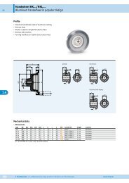
MB100<br />
DEUTSCH<br />
<strong>MSK1000</strong><br />
Sensordarstellungen sind exemplarisch und gültig<br />
für alle Bauformen, sofern nicht gesondert beschrieben.<br />
1. Gewährleistungshinweise<br />
•<br />
•<br />
•<br />
•<br />
Lesen Sie vor der Montage und der Inbetriebnahme<br />
dieses Dokument sorgfältig durch. Beachten Sie zu<br />
Ihrer eigenen Sicherheit und der Betriebssicherheit<br />
alle Warnungen und Hinweise.<br />
Ihr Produkt hat unser Werk in geprüftem und betriebsbereitem<br />
Zustand verlassen. Für den Betrieb<br />
gelten die angegeben Spezifikationen und die<br />
Angaben auf dem Typenschild als Bedingung.<br />
Garantieansprüche gelten nur für Produkte der<br />
Firma <strong>SIKO</strong> <strong>GmbH</strong>. Bei dem Einsatz in Verbindung<br />
mit Fremdprodukten besteht für das Gesamtsystem<br />
kein Garantieanspruch.<br />
Reparaturen dürfen nur im Werk vorgenommen<br />
werden. Für weitere Fragen steht Ihnen die Firma<br />
<strong>SIKO</strong> <strong>GmbH</strong> gerne zur Verfügung.<br />
2. Identifikation<br />
Benutzerinformation<br />
<strong>MSK1000</strong> <strong>Magnetsensor</strong><br />
MB100 <strong>Magnetband</strong><br />
<strong>Magnetband</strong>: Das <strong>Magnetband</strong> ist durch eine fortlaufende<br />
Bedruckung identifizierbar.<br />
MBxxxx GEK WT RP NNNNNN<br />
Chargennummer<br />
Referenzpunkt<br />
Werkstoff-Trägerband<br />
Genauigkeit<br />
MB Typ<br />
<strong>Magnetsensor</strong>: Das Typenschild zeigt den Gerätetyp<br />
mit Variantennummer. Die Lieferpapiere<br />
ordnen jeder Variantennummer eine detaillierte<br />
Bestellbezeichnung zu.<br />
z.B. <strong>MSK1000</strong>-0023<br />
Varianten-Nr.<br />
Geräte-Typ<br />
3. Mechanische Montage<br />
Die Montage darf nur gemäß der angegebenen IP-<br />
Schutzart vorgenommen werden. Das System muss<br />
ggfs. zusätzlich gegen schädliche Umwelteinflüsse,<br />
wie z.B. Spritzwasser, Lösungsmittel, Staub,<br />
Schläge, Vibrationen, starke Temperaturschwankungen<br />
geschützt werden.<br />
3.1 Montage <strong>Magnetband</strong><br />
Die Montage muss plan zur Montagefläche bzw. der<br />
zu messenden Strecke erfolgen. Welligkeiten verschlechtern<br />
immer die Messgenauigkeit.<br />
Aus technischen Gründen muss bei der Länge,<br />
gegenüber der Messstrecke, ein Zumaß von min.<br />
56mm berücksichtigt werden.<br />
Achtung! Um optimale Verklebungen zu erreichen<br />
müssen alle antiadhäsiven Fremdsubstanzen<br />
(Öl, Fett, Staub usw.) durch möglichst rückstandslos<br />
verdunstende Reinigungsmittel entfernt werden.<br />
Als Reinigungsmittel eignen sich u.a. Ketone<br />
(Aceton) oder Alkohole, die u.a. von den Firmen<br />
Loctite und 3M als Schnellreiniger angeboten werden.<br />
Die Klebeflächen müssen trocken sein und es<br />
ist mit höchstmöglichem Anpreßdruck zu verkleben.<br />
Die Verklebungstemperatur ist optimal zwischen<br />
20°C und 30°C in trockenen Räumen.<br />
Tip! Bei Verklebung langer Bänder sollte die<br />
Schutzfolie des Klebebandes über eine kurze Teilstrecke<br />
abgezogen werden, um das Band zu fixieren.<br />
Daraufhin erfolgt das Ausrichten des Bandes.<br />
Nun kann über die restliche Länge die Schutzfolie,<br />
unter gleichzeitigem Andruck des Bandes, seitlich<br />
herausgezogen werden (als Hilfsmittel kann eine<br />
Tapetenandrückwalze verwendet werden).<br />
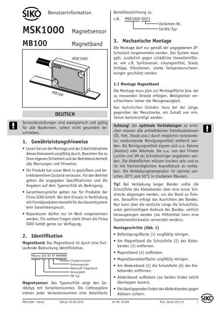
Montageschritte (Abb. 1)<br />
• Befestigungsfläche (1) sorgfältig reinigen.<br />
Am <strong>Magnetband</strong> die Schutzfolie (2) des Klebebandes<br />
(3) entfernen.<br />
• <strong>Magnetband</strong> (4) aufkleben.<br />
• <strong>Magnetband</strong>oberfläche sorgfältig reinigen.<br />
Am Abdeckband (5) die Schutzfolie (6) des Klebebandes<br />
entfernen.<br />
Abdeckband aufkleben (an beiden Enden leicht<br />
überlappen lassen).<br />
Die überlappenden Enden des Abdeckbandes gegen<br />
Ablösen sichern.<br />
<strong>MSK1000</strong> + MB100 Datum 30.08.2010 Art.Nr. 83389 Änd. Stand 292/10 1<br />
•<br />
•<br />
•<br />
•
Abb. 1: Montage <strong>Magnetband</strong><br />
Achtung! Die Beeinflussung durch magnetische<br />
Felder ist zu vermeiden. Insbesondere dürfen keine<br />
Magnetfelder (z.B. Haftmagnete oder andere Dauermagnete)<br />
in direkten Kontakt mit dem <strong>Magnetband</strong><br />
geraten. In stromlosem Zustand werden Bewegungen<br />
oder Verstellungen des <strong>Magnetsensor</strong>s<br />
von der Folgeelektronik nicht erkannt und erfasst.<br />
Montagebeispiele<br />
Die einfache Montageart, durch angeschrägtes<br />
Schutzband (Abb. 2), ist nur in sehr geschützter<br />
Umgebung zu empfehlen. Bei ungeschützer Umgebung<br />
besteht Abschälgefahr. In solchen Fällen<br />
sind Montagearten, wie in Abb. 3 und 4 gezeigt,<br />
geeigneter.<br />
Den optimalen Schutz bietet die Montage in einer<br />
Nut (Abb. 5), die so tief sein sollte, dass das<br />
<strong>Magnetband</strong> vollständig darin eingebettet werden<br />
kann.<br />
Abb. 2 Abb. 3<br />
Abb. 4 Abb. 5<br />
3.2 Montage <strong>Magnetsensor</strong> <strong>MSK1000</strong><br />
Der <strong>Magnetsensor</strong> <strong>MSK1000</strong> kann durch Verwendung<br />
von 2 Schrauben M3 über die Langlöcher<br />
befestigt werden. Es wird empfohlen die beiliegenden<br />
Befestigungsschrauben und Federringe zu<br />
verwenden (Anzugsmoment 1Nm).<br />
•<br />
•<br />
Kabel sind so zu verlegen, dass keine Beschädigungsgefahr<br />
besteht. Zugentlastung und<br />
wenn nötig Schleppkette oder Schutzschlauch<br />
vorsehen.<br />
Auf richtige Ausrichtung bezüglich der Zählrichtung<br />
achten (Abb. 6). Dies ist unerheblich<br />
falls sich die Zählrichtung in der elektronischen<br />
Auswertung umkehren läßt (wie z.B. bei den<br />
<strong>Magnetband</strong>anzeigen von <strong>SIKO</strong>).<br />
Abstandslehre vollflächig zwischen Sensor und<br />
<strong>Magnetband</strong> legen. Hinweis: Betrifft nur Sensoren<br />
ohne Referenzsignal R.<br />
Achtung! Die Toleranz- und Abstandsmaße müssen<br />
über die gesamte Messstrecke eingehalten<br />
werden. Der maximale Abstand ohne Abdeckband<br />
beträgt 0,4mm. Bei Verwendung eines Abdeckbandes<br />
reduziert sich der eff. Abstand um die Dicke<br />
des Abdeckbandes inkl. Klebefolie. Der Sensor darf<br />
das <strong>Magnetband</strong> nicht berühren.<br />
Anwendung LINEAR <strong>MSK1000</strong> mit MB100:<br />
Signal<br />
A vor B<br />
Kabelabgangsrichtung<br />
Verfahrrichtung<br />
aktive Seite<br />
Abstand Sensor/<strong>Magnetband</strong><br />
< 1°<br />
Maximale Fluchtungsfehler<br />
Referenzpunktlage zur <strong>Magnetband</strong>bedruckung<br />
MBxxxx GEK WT RP NNNNNN<br />
2 <strong>MSK1000</strong> + MB100 Datum 30.08.2010 Art.Nr. 83389 Änd. Stand 292/10<br />
•<br />
0.1mm ... 0.4mm<br />
ohne Referenzpunkt<br />
< 3°<br />
0.1mm ... 0.2mm<br />
mit Referenzpunkt<br />
< 3°<br />
Zul. Abweichung<br />
Mitte Band/Sensor:<br />
ohne Ref. ±2mm<br />
mit Ref. ±0.5mm
10<br />
Symbolische Darstellung<br />
der Pole<br />
Referenzpunkt periodisch<br />
Lage Ref.Punkt R=entspr. Lieferpapiere<br />
Einmaliger Referenzpunkt<br />
Lage Ref.Punkt E=entspr. Lieferpapiere<br />
min. 0,01m<br />
Abb. 6: Definition der Zählrichtung mit <strong>Magnetband</strong><br />
und Montage Sensor/<strong>Magnetband</strong>, Abstandsmaße,<br />
Toleranzen<br />
4. Elektrischer Anschluss<br />
•<br />
•<br />
Verdrahtungsarbeiten dürfen nur spannungslos<br />
erfolgen!<br />
Vor dem Einschalten sind alle Leitungsanschlüsse<br />
und Steckverbindungen zu überprüfen.<br />
Hinweise zur Störsicherheit<br />
Alle Anschlüsse sind gegen äußere Störeinflüsse<br />
geschützt. Der Einsatzort ist aber so zu wählen,<br />
dass induktive oder kapazitive Störungen nicht<br />
auf den Sensor oder dessen Anschlussleitung<br />
einwirken können! Durch geeignete Kabelführung<br />
und Verdrahtung können Störeinflüsse (z.B.von<br />
Schaltnetzteilen, Motoren, getakteten Reglern<br />
oder Schützen) vermindert werden.<br />
Erforderliche Maßnahmen:<br />
•<br />
•<br />
•<br />
•<br />
Nur geschirmtes Kabel verwenden. Den Kabelschirm<br />
beidseitig auflegen. Litzenquerschnitt der<br />
Leitungen min. 0,14mm²; max.0,5mm².<br />
Die Verdrahtung von Abschirmung und Masse (0V)<br />
muss sternförmig und großflächig erfolgen. Der Anschluss<br />
der Abschirmung an den Potentialausgleich<br />
muss großflächig (niederimpedant) erfolgen.<br />
Das System muss in möglichst großem Abstand von<br />
Leitungen eingebaut werden, die mit Störungen<br />
belastet sind; ggfs. sind zusätzliche Maßnahmen<br />
wie Schirmbleche oder metallisierte Gehäuse<br />
vorzusehen. Leitungsführungen parallel zu Energieleitungen<br />
vermeiden.<br />
Schützspulen müssen mit Funkenlöschgliedern<br />
beschaltet sein.<br />
Spannungsversorgung<br />
Die Spannungswerte sind abhängig von der Sensorausführung<br />
und sind den Lieferpapieren sowie<br />
dem Typenschild zu entnehmen.<br />
z.B.: 6,5VDC ... 30VDC<br />
Achtung! Die maximale Länge des Anschlusskabels<br />
zwischen Sensor und Nachfolgeelektronik beachten.<br />
4.1 Anschlusshinweis nach RS422 Norm<br />
Es ist darauf zu achten, dass die Kanäle mit einem<br />
Abschlusswiderstand von 120 Ohm abgeschlossen<br />
werden.<br />
4.2 Anschlussarten<br />
E1: Anschluss mit offenen Kabelenden.<br />
Achtung! Verzinnte Litzen dürfen nicht in Verbindung<br />
mit Schraubklemmverbindungen eingesetzt<br />
werden.<br />
so kurz wie<br />
möglich<br />
<strong>MSK1000</strong> + MB100 Datum 30.08.2010 Art.Nr. 83389 Änd. Stand 292/10 3<br />
1.<br />
2.<br />
3.<br />
invertiert invertiert mit Indexsignal Signal<br />
rot rot A<br />
orange orange B<br />
- - - blau I, R<br />
braun braun +UB<br />
schwarz schwarz GND<br />
gelb gelb /A<br />
grün grün /B<br />
- - - violett /I, /R<br />
Ummantelung entfernen.<br />
Schirm auftrennen und verdrillen.<br />
Litzen ca. 5mm abisolieren und verdrillen.<br />
4.<br />
Aderendhülsen aufquetschen.<br />
Schirm<br />
Abb. 7: Anschluss E1<br />
5
E6: Anschluss mit Kupplungsstecker und Kupplungsdose.<br />
Steckermontage entsprechend Abb. 8.<br />
Signal invertiert invertiert mit<br />
Indexsignal<br />
A Pin 1 Pin 1<br />
B 2 2<br />
I, R - - - 3<br />
+UB 4 4<br />
GND 5 5<br />
/A 6 6<br />
/B 7 7<br />
/I, /R - - - 8<br />
- - - 3<br />
1.<br />
2.<br />
3.<br />
4.<br />
5.<br />
6.<br />
7.<br />
8.<br />
9.<br />
Schirm<br />
Buchsenteil<br />
Stiftteil<br />
Abb. 8: Montage Anschlussart E6<br />
Ansichtseite<br />
= Steckseite<br />
Stifteinsatz<br />
Pos. 6 ... 10 über Kabelmantel schieben.<br />
Kabel abisolieren.<br />
Schirm umlegen.<br />
Pos. 5 auf Litzen schieben.<br />
Litzen an Pos. 3 löten (entspr. Anschlussplan).<br />
Abstandhülse Pos. 4 aufweiten und über Litzen<br />
stülpen, zusammendrücken und auf Pos. 3 stecken.<br />
Schlitz und Nut (Pos. 3 und 4) müssen<br />
deckungsgleich sein.<br />
Pos. 6 an Pos. 5 drücken, überstehenden Schirm<br />
abschneiden.<br />
Pos. 2 und 7 aufschieben und mittels Montagewerkzeug<br />
Pos. 11 verschrauben.<br />
Pos. 8 in Pos. 9 stecken, beides in Pos. 7<br />
schieben.<br />
10. Pos. 10 mit Pos. 7 verschrauben.<br />
11. Pos. 1 in Pos 2. schieben.<br />
Schirm<br />
E8: Anschluss mit 9-poligem D-SUB Stecker<br />
A B I/R Power<br />
Ansichtseite = Steckseite<br />
Stifteinsatz<br />
Signal invertiert invertiert mit Indexsignal<br />
A Pin 1 Pin 1<br />
B 2 2<br />
I, R - - - 3<br />
+UB 4 4<br />
GND 5 5<br />
/A 6 6<br />
/B 7 7<br />
/I, /R - - - 8<br />
- - - 3, 8, 9 9<br />
E14X: Anschluss mit 9-poligem Stecker.<br />
Signal invertiert invertiert mit<br />
Indexsignal<br />
A Pin 1 Pin 1<br />
B 2 2<br />
I, R - - - 3<br />
+UB 8 8<br />
GND 7 7<br />
/A 4 4<br />
/B 5 5<br />
/I, /R - - - 6<br />
- - - 3,6 ---<br />
Schirm 9 9<br />
5. Inbetriebnahme<br />
Ansichtseite =<br />
Steckseite<br />
Stiftkontakt<br />
Nach ordnungsgemäßer Montage und Verdrahtung<br />
kann das Messsystem durch Einschalten der Versorgungsspannung<br />
in Betrieb genommen werden.<br />
Das Gerät initialisiert sich selbstständig nach dem<br />
Einschalten.<br />
Nur Bauform "M": Die "Power"-Leuchtdiode (grün)<br />
im Sensorgehäuse leuchtet. Beim Verfahren des<br />
<strong>Magnetsensor</strong>s über das <strong>Magnetband</strong> blinken die<br />
Leuchtdioden A, B und I/R (rot) entsprechend<br />
auf.<br />
4 <strong>MSK1000</strong> + MB100 Datum 30.08.2010 Art.Nr. 83389 Änd. Stand 292/10
Das Messsystem <strong>MSK1000</strong>/MB100 ist Bestandteil<br />
eines inkrementalen Messsystem, dass zur absoluten<br />
Messung an einer definierten Stelle (Referenzpunkt)<br />
referenziert werden muss. Dazu muss<br />
das Referenzsignal mit dem Signal eines Referenzwertgebers<br />
(z.B. Näherungsschalter) verknüpft<br />
werden.<br />
6. Verfahrgeschwindigkeiten (m/s)<br />
Formel zur Berechnung der Verfahrgeschwindigkeit:<br />
Beispiel:<br />
V max. =<br />
(in m/s)<br />
Auflösung in µm<br />
Pulsabstand in µs<br />
Auflösung: 1µm<br />
Pulsabstand: 0,25µs<br />
V =<br />
1<br />
x 0,8 = 3,2m/s<br />
0,25<br />
Verfahrgeschwindigkeit<br />
in m/s<br />
Auflösung in µm<br />
0,2 1 2 5<br />
Pulsabstand<br />
(µs)<br />
Zählfrequenz<br />
(kHz)<br />
0,64 3,20 6,40 16,00 0,25 1000,00<br />
0,32 1,60 3,20 8,00 0,50 500,00<br />
0,16 0,80 1,60 4,00 1,00 250,00<br />
0,08 0,40 0,80 2,00 2,00 125,00<br />
7. Ausgangssignale<br />
x 0,8<br />
Die Auswerteelektronik setzt die magnetischen<br />
Längeninformationen des <strong>Magnetsensor</strong>s in inkrementale<br />
Ausgangssignale um. Die Ausgabe der<br />
Signale erfolgt geschwindigkeitsproportional.<br />
Es ist zu beachten, dass im Stillstand Impulse<br />
von der Breite des eingestellten Pulsabstandes<br />
auftreten können (bedingt durch das interne Interpolationsverfahren).<br />
Achtung! Bei der Dimensionierung der Nachfolgeelektronik<br />
ist zu beachten, dass diese für den<br />
eingestellten Pulsabstand bzw. Zählfrequenz ausgelegt<br />
ist.<br />
Signalfolge<br />
Hinweis: Die Lage des Index- bzw. Referenzsignals<br />
I+R zu den Signalen A und B ist nicht definiert und<br />
kann von der Zeichnung abweichen.<br />
Hinweis: Bei Index-/Referenzsignalbreite von 4<br />
Inkrementen (= 360°), ist der Index/Referenz erst<br />
nach dem 5. Zählschritt (Inkrement) auswertbar.<br />
Nach dem Einschalten der Betriebsspannung entsprechende<br />
Verzögerung berücksichtigen.<br />
8. Wartung<br />
Die Oberfläche des <strong>Magnetband</strong>es ist bei starker<br />
Verschmutzung durch Staub, Späne, Feuchtigkeit<br />
usw., von Zeit zu Zeit mit einem weichen Lappen<br />
zu reinigen.<br />
9. Fehlerbehandlung<br />
Typische Fehler, die bei Anbau und Betrieb auftreten:<br />
Das <strong>Magnetband</strong> wurde falsch montiert / aktive<br />
Seite nach unten (Kapitel 3.1).<br />
Zum Schutz des <strong>Magnetband</strong>es wurde nicht das<br />
mitgelieferte Abdeckband verwendet. Das Abdeckband<br />
muss nicht magnetisierbar sein.<br />
Der Sensor ist nicht, oder nicht korrekt angeschlossen<br />
(Pinbelegung Kapitel 4.2).<br />
Die Abstandstoleranz zwischen Sensor und <strong>Magnetband</strong>/Magnetring<br />
wurde nicht eingehalten<br />
(beim Band über die gesamte Messstrecke!), der<br />
Sensor streift auf dem Magnetring (Abb. 6).<br />
Kabelunterbrechung / Abtrennung durch scharfe<br />
Kanten / Quetschung.<br />
Der Sensor ist mit der aktiven Seite vom Band<br />
abgewandt montiert (Abb. 6).<br />
Der Sensor wurde nicht entsprechend Abb. 6<br />
ausgerichtet.<br />
<strong>MSK1000</strong> + MB100 Datum 30.08.2010 Art.Nr. 83389 Änd. Stand 292/10 5<br />
•<br />
•<br />
•<br />
•<br />
•<br />
•<br />
•
6 <strong>MSK1000</strong> + MB100 Datum 30.08.2010 Art.Nr. 83389 Änd. Stand 292/10
MB100<br />
ENGLISH<br />
<strong>MSK1000</strong><br />
Exemplary sensor illustrations are valid for all sensor<br />
types unless described separately.<br />
1. Warranty information<br />
•<br />
•<br />
•<br />
•<br />
In order to carry out installation correctly, we<br />
strongly recommend this document is read very<br />
carefully. This will ensure your own safety and<br />
the operating reliability of the device.<br />
Your device has been quality controlled, tested<br />
and is ready for use. Please observe all warnings<br />
and information which are marked either directly<br />
on the device or specified in this document.<br />
Warranty can only be claimed for components<br />
supplied by <strong>SIKO</strong> <strong>GmbH</strong>. If the system is used<br />
together with other products, there is no warranty<br />
for the complete system.<br />
Repairs should be carried out only at our works.<br />
If any information is missing or unclear, please<br />
contact the <strong>SIKO</strong> sales staff.<br />
2. Identification<br />
User Information<br />
<strong>MSK1000</strong> Magnetic sensor<br />
MB100 Magnetic strip<br />
Magnetic strip: identification by printing on the<br />
strip.<br />
MBxxxx GEK WT RP NNNNNN<br />
batch number<br />
reference point<br />
carrier strip<br />
accuracy<br />
MB type<br />
Magnetic sensor: Please check the particular type<br />
of unit and type number from the identification<br />
plate. Type number and the corresponding version<br />
are indicated in the delivery documentation.<br />
e.g. <strong>MSK1000</strong>-0023<br />
3. Installation<br />
version number<br />
type of unit<br />
For mounting, the degree of protection specified<br />
must be observed. If necessary, protect the unit<br />
against environmental influences such as sprayed<br />
water, dust, knocks, extreme temperatures.<br />
3.1 Mounting the magnetic strip<br />
The mounting surface / measuring track must be<br />
flat. Buckles or bumps will lead to measuring inaccuracies.<br />
For technical reasons the strip should be min.<br />
56mm longer than the actual measuring distance.<br />
Attention! To guarantee optimal adhesion oil,<br />
grease dust etc. must be removed by using cleansing<br />
agents which evaporate without leaving residues.<br />
Suitable cleansing agents are eg. ketones<br />
(acetone) or alcohols; Messrs. Loctite and 3M can<br />
both supply such cleansing liquid. Make sure that<br />
the surface to be glued is dry and apply the strip<br />
with maximum pressure. Glueing should preferably<br />
be undertaken at temperatures between 20°C to<br />
30°C and in dry atmosphere.<br />
Advice! Wh en applying long pieces of magnetic<br />
strip do not immediately remove the complete protective<br />
foil, but rather peel back a short part from<br />
the end sufficient to fix the strip. Now align the<br />
strip. As the protective strip is then peeled back<br />
and out press the tape firmly onto the mounting<br />
surface. A wall paper roller wheel could be used to<br />
assist in applying pressure onto the magnetic strip<br />
when fixing it in position.<br />
Mounting steps (see fig. 1)<br />
• Clean mounting surface (1) carefully.<br />
Remove protective foil (2) from the adhesive<br />
side of the magnetic strip (3).<br />
• Stick down the magnetic strip (4).<br />
• Clean surface of magnetic strip carefully.<br />
Remove protective foil (6) from adhesive tape on<br />
the cover strip (5).<br />
Fix cover strip (both ends should slightly overlap).<br />
Also fix cover strip's ends to avoid unintentional<br />
peeling.<br />
<strong>MSK1000</strong> + MB100 Datum 30.08.2010 Art.Nr. 83389 Änd. Stand 292/10 7<br />
•<br />
•<br />
•<br />
•
Fig. 1: Mounting of the magnetic strip<br />
Attention! Do not expose the system to magnetic<br />
fields. Any direct contact of the magnetic strip<br />
with magnetic fields (eg. adhesive magnets or<br />
other permanent magnets) is to be avoided. Sensor<br />
movements during power loss are not captured<br />
by the follower electronics.<br />
Mounting examples<br />
Mounting with chamfered ends (fig. 2) is not recommended<br />
unless the strip is installed in a safe<br />
and protected place without environmental influences.<br />
In less protected mounting places the strip<br />
may peel. There we recommend mounting accord.<br />
to fig. 3 and 4.<br />
Mounting in a groove (fig. 5) best protects the<br />
magnetic strip. The groove should be deep enough<br />
to totally embed the magnetic strip.<br />
Fig. 2 Fig. 3<br />
Fig. 4 Fig. 5<br />
3.2 Mounting of the magnetic sensor <strong>MSK1000</strong><br />
The magnetic sensor <strong>MSK1000</strong> can be fastened by<br />
using two bolts M3 over the elongated holes. We<br />
recommend to use the enclosed fixing screws and<br />
washer springs (fastening torque 1Nm).<br />
•<br />
Cables should be layed in such a way that there<br />
is no danger of damaging. Provide ten-sion relief<br />
and drag chain or casing, if necessary.<br />
•<br />
Observe the correct alignment with regard to<br />
the counting direction (fig. 6). This does not<br />
apply if the counting direction can be reversed<br />
in the electronic interpretation (e.g. in <strong>SIKO</strong>'s<br />
magnetic-strip displays).<br />
Travel direction<br />
Signal<br />
A before B<br />
active side<br />
Direction<br />
of outgoing<br />
cable<br />
Magnetic poles -<br />
schema<br />
Gap sensor/magnetic strip<br />
< 1°<br />
Periodical reference point<br />
Position of the reference point R = as<br />
stated in the delivery documentation<br />
Unique reference point<br />
Position of the reference point E = as stated<br />
in the delivery documentation; min. 0,01m<br />
Fig. 6: Definition of the counting direction with<br />
magnetic strip and assemblage sensor/magnetic ring,<br />
gap measure, tolerances<br />
8 <strong>MSK1000</strong> + MB100 Datum 30.08.2010 Art.Nr. 83389 Änd. Stand 292/10<br />
•<br />
Place distance gauge with its complete surface<br />
between sensor and magnetic tape. Note: only<br />
relevant for sensors without reference signal R.<br />
Attention! The tolerance and gap measures must<br />
be observed over the whole measuring length.<br />
The max. gap without cover strip is 0,4mm. When<br />
using cover strip, the gap is reduced by the thickness<br />
of cover strip including its adhesive tape.<br />
Sensor must not touch the magnetic strip.<br />
LINEAR application <strong>MSK1000</strong> with MB100:<br />
10<br />
Maximum alignment error<br />
Position of the reference point relating<br />
to the marking on the magnetic strip.<br />
MBxxxx GEK WT RP NNNNNN<br />
0.1mm ... 0.4mm without<br />
reference point<br />
< 3°<br />
0.1mm ... 0.2mm with<br />
reference point<br />
< 3°<br />
Admissable deviatoion<br />
middle of tape/sensor:<br />
without ref. point ±2mm<br />
with ref. point ±0.5mm
4. Electrical connection<br />
• Wiring must only be carried out with power off!<br />
•<br />
Check all lines and connections before switching<br />
on the equipment!<br />
Interference and distortion<br />
All connections are protected against the effects<br />
of interference. The location should be selected<br />
to ensure that no capacitive or inductive interferences<br />
can affect the sensor or the connection<br />
lines! Suitable wiring layout and choice<br />
of cable can minimise the effects of interference<br />
(eg. interference caused by SMPS, motors, cyclic<br />
controls and contactors).<br />
Necessary measures:<br />
•<br />
•<br />
•<br />
•<br />
Only screened cable should be used. Wire cross section<br />
is to be at least 0,14mm², max. 0,5mm².<br />
Wiring to the screen and ground (0V) must<br />
be secured to a good point. Ensure that the<br />
connection of the screen and earth is made to<br />
a large surface area with a sound connection to<br />
minimise impedance.<br />
The system should be positioned well away from<br />
cables with interference; if necessary a protective<br />
screen or metal housing must be provided. The<br />
running of wiring parallel to the mains supply<br />
should be avoided.<br />
Contactor coils must be linked with spark suppression.<br />
Supply voltage<br />
The voltages depend on the sensor designs; they<br />
are to be taken from the delivery documentation<br />
and the identification plate.<br />
e.g.: 6,5VDC ... 30VDC<br />
Attention! When connecting sensor and follower<br />
electronics, please do not exceed the max. admissable<br />
cable length.<br />
4.1 Connection note acc. to RS422 standard<br />
Please provide the channels with a 120 Ohm terminating<br />
resistor.<br />
4.2 Connection type<br />
E1: Flying leads.<br />
Attention! Tinned strands must not used in combination<br />
with screw/clamp connections.<br />
inverted inverted with reference<br />
signal<br />
Signal<br />
red red A<br />
orange orange B<br />
- - - blue I, R<br />
brown brown +UB<br />
black black GND<br />
yellow yellow /A<br />
green green /B<br />
- - - violet /I, /R<br />
Remove cable coating.<br />
Open screening and twist it.<br />
Strip stranded wires to a length of 5mm and<br />
twist them.<br />
Pinch stranded wires.<br />
screening<br />
Fig. 7: Connection type E1<br />
as short as<br />
possible<br />
<strong>MSK1000</strong> + MB100 Datum 30.08.2010 Art.Nr. 83389 Änd. Stand 292/10 9<br />
1.<br />
2.<br />
3.<br />
4.<br />
E6: Connection with mit coupler plug and coupler<br />
socket. Plug mounting according to fig. 8.<br />
Signal inverted inverted with<br />
reference signal<br />
A Pin 1 Pin 1<br />
B 2 2<br />
I, R - - - 3<br />
+UB 4 4<br />
GND 5 5<br />
/A 6 6<br />
/B 7 7<br />
/I, /R - - - 8<br />
- - - 3<br />
1.<br />
2.<br />
3.<br />
4.<br />
5.<br />
Slip parts 6 to 10 over outer cable.<br />
Strip cable.<br />
Turn down screening.<br />
Push part 5 onto ferrules.<br />
5<br />
viewing side =<br />
plug-in side<br />
male contact<br />
Solder wires to part 3 (according connection<br />
diagram).<br />
6.<br />
Open spacer (part 4) and put it over ferrules,
7.<br />
8.<br />
9.<br />
squeeze and push it onto part 3. Slot and keyway<br />
of parts 3 and 4 must align.<br />
Press parts 6 and 5 together; cut prodruding<br />
screening.<br />
Push parts 2 and 7 together and screw part 11<br />
using appropriate tool.<br />
Push part 8 into part 9 and slide both parts<br />
into part 7.<br />
10. Screw parts 10 and 7 together.<br />
11. Push part 1 into part 2.<br />
screening<br />
pin<br />
Fig. 8: Coupler socket E6<br />
socket<br />
E8: Connection with 9-pole D-SUB plug<br />
screening<br />
viewing side = plug-in side<br />
male contact<br />
Signal inverted inverted with reference<br />
signal<br />
A Pin 1 Pin 1<br />
B 2 2<br />
I, R - - - 3<br />
+UB 4 4<br />
GND 5 5<br />
/A 6 6<br />
/B 7 7<br />
/I, /R - - - 8<br />
- - - 3, 8, 9 9<br />
E14X: Connection with 9-pole plug<br />
Signal inverted inverted with<br />
reference signal<br />
A Pin 1 Pin 1<br />
B 2 2<br />
I, R - - - 3<br />
+UB 8 8<br />
Signal inverted inverted with<br />
reference signal<br />
GND 7 7<br />
/A 4 4<br />
/B 5 5<br />
/I, /R - - - 6<br />
- - - 3,6 --shielding<br />
9 9<br />
5. Commissioning<br />
A B I/R Power<br />
viewing side=<br />
plug-in side<br />
plug pin<br />
Following proper installation and wiring, the<br />
measuring system can be commissioned by<br />
switching on the supply voltage. After switching<br />
on, the device initializes itself independently.<br />
Only design "M": The "power" LED (green) in the<br />
sensor housing lights up. While the magnetic sensor<br />
travels over the magnetic strip, the LEDs A, B,<br />
and I/R (red) are lighting accordingly.<br />
The measuring system <strong>MSK1000</strong>/MB100 is a component<br />
of an incremental measuring system which<br />
must be referenced at a defined position (reference<br />
point) for absolute measurement. For this<br />
purpose, the reference signal must be linked to<br />
the signal of a reference value encoder (e.g., proximity<br />
switch).<br />
6. Travel speeds (m/s)<br />
Formula for calculating the travel speed:<br />
V max. =<br />
(in m/s)<br />
Example:<br />
Resolution: 1µm<br />
Pulse interval: 0,25µs<br />
Resolution in µm<br />
x 0,8<br />
Pulse interval in µs<br />
10 <strong>MSK1000</strong> + MB100 Datum 30.08.2010 Art.Nr. 83389 Änd. Stand 292/10<br />
V =<br />
1<br />
x 0,8 = 3,2m/s<br />
0,25
Travel speed<br />
m/s<br />
Resolution in µm<br />
0,2 1 2 5<br />
Pulse interval<br />
(µs)<br />
Counting<br />
frequency<br />
(kHz)<br />
0,64 3,20 6,40 16,00 0,25 1000,00<br />
0,32 1,60 3,20 8,00 0,50 500,00<br />
0,16 0,80 1,60 4,00 1,00 250,00<br />
0,08 0,40 0,80 2,00 2,00 125,00<br />
7. Output signals<br />
The translation module translates the length<br />
information of the magnetic sensor into incre-<br />
mental output signals with real-time processing of<br />
the output signals.<br />
Please note that pulses having the width of<br />
the pulse interval set can occur at standstill of<br />
the device (caused by the internal interpolation<br />
method).<br />
Caution! When dimensioning the follow-on electronics<br />
please take care that it is adjusted to the<br />
set pulse interval or counting frequency, respectively.<br />
Signal sequence<br />
Note: The position of the index or reference signal<br />
I+R, respectively, with respect to signals A<br />
and B is not defined and can deviate from the<br />
drawing.<br />
Note: With a 4-increment wide (= 360°) index/<br />
reference signal, index/reference signal interpretation<br />
can be made after the 5th counting step<br />
(increment) only. Corresponding time delay has to<br />
be considered when power is switched on.<br />
8. Maintenance<br />
We recommend cleaning the magnetic strip’s surface<br />
from time to time with a soft rag. This avoids<br />
dirt (dust, chips, humidity ...) sticking to the<br />
strip.<br />
9. Trouble shooting<br />
Below are some typical errors which may occur during<br />
installation and operation:<br />
Magnetic strip incorrectly mounted (active surface<br />
must be mounted towards the sensor) (see<br />
chapter 3.1).<br />
Use of foreign protective strip. Must always be<br />
non-magnetic.<br />
Sensor not or incorrectly connected (pin connection,<br />
see chapter 4.2).<br />
Tolerance for the gap between magnetic sensor and<br />
magnetic strip not observed over the total travel<br />
distance. Sensor touches strip (see fig. 6).<br />
Cable squeezed / interrupted / cut by sharp<br />
edges.<br />
Sensor's active side not mounted towards the<br />
magnetic strip (see fig. 6).<br />
•<br />
Sensor has not been aligned according to fig.<br />
6.<br />
<strong>MSK1000</strong> + MB100 Datum 30.08.2010 Art.Nr. 83389 Änd. Stand 292/10 11<br />
•<br />
•<br />
•<br />
•<br />
•<br />
•
<strong>SIKO</strong> <strong>GmbH</strong><br />
Werk / Factory:<br />
Weihermattenweg 2<br />
79256 Buchenbach-Unteribental<br />
Postanschrift / Postal address:<br />
Postfach 1106<br />
79195 Kirchzarten<br />
Telefon/Phone +49 7661 394-0<br />
Telefax/Fax +49 7661 394-388<br />
E-Mail info@siko.de<br />
Internet www.siko.de<br />
Service support@siko.de<br />
12 <strong>MSK1000</strong> + MB100 Datum 30.08.2010 Art.Nr. 83389 Änd. Stand 292/10