ProTool DE - SIKO Products USA
ProTool DE - SIKO Products USA
ProTool DE - SIKO Products USA

Sie wollen auch ein ePaper? Erhöhen Sie die Reichweite Ihrer Titel.
YUMPU macht aus Druck-PDFs automatisch weboptimierte ePaper, die Google liebt.
Benutzerinformation<br />
<strong>ProTool</strong> <strong>DE</strong><br />
Programmiersoftware für <strong>DE</strong>04 und <strong>DE</strong>10<br />
<strong>DE</strong>UTSCH<br />
1. Gewährleistungshinweise<br />
• Bitte lesen Sie vor der Installation und der Inbetriebnahme<br />
dieses Dokument sorgfältig durch und<br />
beachten Sie alle Hinweise.<br />
• Für den Betrieb gelten die angegeben Spezifikationen<br />
und technischen Daten als Bedingung.<br />
• Für weitere Fragen steht Ihnen die Firma <strong>SIKO</strong><br />
GmbH gerne zur Verfügung.<br />
• Garantieansprüche gelten nur für Produkte der<br />
Firma <strong>SIKO</strong> GmbH. Bei dem Einsatz in Verbindung<br />
mit Fremdprodukten besteht für das Gesamtsystem<br />
kein Garantieanspruch.<br />
2. Kurzbeschreibung<br />
Die Programmier-Software <strong>ProTool</strong> <strong>DE</strong> bietet unter<br />
Windows 98/NT/2000/XP/Vista/7 die Möglichkeit,<br />
die Positionsanzeige schon vor der Montage mit<br />
entsprechenden Parametern zu programmieren.<br />
Der Umgang mit dem Programm ist sehr einfach, da<br />
die Funktionen mit Bezeichnungen benannt sind,<br />
die aus den Bestellmerkmalen der Positionsanzeige<br />
bekannt sind. Die Werte werden direkt eingegeben<br />
oder mittels Schaltflächen ausgewählt. Die Eingabe<br />
von unzulässigen Werten wird von der Software<br />
erkannt.<br />
3. Installation<br />
Vor dem Einsatz von <strong>ProTool</strong> <strong>DE</strong> müssen die entsprechend<br />
Treiber passend zur verwendeten Windows-<br />
Version installiert werden.<br />
3.1 Treiberinstallation<br />
Die Installation der USB-Treiber ist pro Rechner nur<br />
einmalig notwendig. Passend zur jeweiligen Windows-Version<br />
befinden sich verschiedene Ordner<br />
auf der Installations-CD. Im entsprechenden Ordner<br />
findet sich die Anwendungsdatei "CDM 2.04.06.<br />
EXE", die zu starten ist. Dadurch werden die Treiber<br />
auf dem Rechner automatisch installiert.<br />
Hinweis: Zur korrekten Installation des Treibers,<br />
muss das Anschlusskabel am USB-Anschluss des<br />
Computers eingesteckt sein.<br />
3.2 Programminstallation<br />
Die Datei "<strong>ProTool</strong><strong>DE</strong>.EXE" kann wahlweise direkt<br />
von der CD aufgerufen werden oder mit Hilfe des<br />
Windows-Explorers in ein beliebiges Verzeichnis<br />
(z.B. auch auf den Desktop) kopiert werden. Das<br />
Programm ist ohne weitere Files direkt lauffähig.<br />
4. Anschluss<br />
Anschluss am Computer<br />
Die Programmierung der digitalen Positionsanzeige<br />
erfolgt über das mitgelieferte Programmierkabel.<br />
Für die Anbindung an die Programmier-Software<br />
muss das Kabel mit einem USB-Anschluss am Computer<br />
verbunden werden.<br />
Anschluss an Positionsanzeige<br />
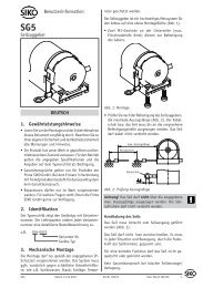
Auf der Rückseite des Geräts befindet sich eine<br />
runde Abdeckkappe, die z.B. mit einem Schraubendreher<br />
leicht entfernt werden kann. Nach Entfernen<br />
der Abdeckkappe kann der Steckanschluss mit den<br />
drei Metallstiften in die dafür vorgesehenen Bohrungen<br />
auf der Leiterplatte eingesteckt werden.<br />
Dabei ist zu beachten, dass der längere der drei Pins<br />
in die untere Bohrung gesteckt wird.<br />
Hinweis: Ein falsch positioniertes Einstecken der<br />
drei Pins führt nicht zu einer Beschädigung des<br />
Geräts. Jedoch wird dabei keine funktionierende<br />
Verbindung zwischen Positionsanzeige und Programmiersoftware<br />
hergestellt.<br />
Abdeckkappe<br />
Programmierkabel<br />
Hinweis: Das Programmierkabel darf nur bei deaktivierter<br />
Kommunikation gesteckt oder getrennt<br />
werden ! Das Umschalten erfolgt mit dem Button<br />
„Start“ bzw „Stop“.<br />
<strong>ProTool</strong> <strong>DE</strong> Datum 26.05.2011 Art.Nr. 84991 Änd. Stand 184/11 1
Trennen der Anschlüsse<br />
Nach erfolgter Programmierung wird das Programmierkabel<br />
von der Positionanzeige und dem USB-<br />
Anschluss getrennt. Anschließend wird die Öffnung<br />
auf der Geräterückseite mit der Abdeckkappe verschlossen<br />
und die lose beigelegte Dichtungsplatte<br />
aufgeklebt.<br />
5. Funktionsbeschreibung<br />
Hinweis: Die Parametrierung ist nur möglich, wenn<br />
die Datenkommunikation eingeschaltet ist !<br />
Software-Version<br />
Die Software-Version wird in der Kopfzeile des Programm-Fensters<br />
angezeigt (z.B. V2.02). Auswahl<br />
der deutschsprachigen Programmierversion durch<br />
Betätigen der Schaltfläche Sprache "Deutsch".<br />
5.1 Einbaulage<br />
Durch Betätigung einer der Schaltflächen wird die<br />
Lesbarkeit des Displays zwischen Einbaulage 02<br />
(horizontale Wellenlage) und Einbaulage 04 (vertikale<br />
Wellenlage) geändert. Die jeweils program-<br />
mierte Ausführung wird im Feld neben der Schaltfläche<br />
angezeigt.<br />
5.2 Messwert/Umdrehung<br />
Der Messwert/Umdr. ist Grundlage für den Anzeigewert,<br />
der nach einer Umdrehung am Gerät angezeigt<br />
werden soll. Zulässig sind ganze Zahlen zwischen<br />
2...90000. Durch Betätigen der Schaltfläche<br />
"Set" wird der eingetragene Wert übergeben.<br />
5.3 Kommastelle<br />
Durch Betätigung einer der Schaltflächen wird der<br />
Wert an die Positionsanzeige übergeben und im nebenstehenden<br />
Infofeld angezeigt.<br />
2 <strong>ProTool</strong> <strong>DE</strong> Datum 26.05.2011 Art.Nr. 84991 Änd. Stand 184/11
Beispiel: Kommastelle Anzeige<br />
1080 0 1080<br />
1 108.0<br />
2 10.80<br />
3 1.080<br />
5.4 Anzeigedivisor<br />
Zur Angabe des Anzeigewerts nach einer Umdrehung<br />
sind die Parameter "Anzeigedivisor" und<br />
"Messwert/Umdr." in Verbindung zu betrachten.<br />
Im Eingabefeld "Messwert/Umdr." ist der Anzeigewert<br />
nach erster Umdrehung als ganze Zahl zu<br />
erfassen. Mit den Schaltflächen beim Parameter<br />
"Anzeigedivisor" kann der Wert 1 – 10 – 100 oder<br />
1000 als Anzeigedivisor gewählt werden. Je nach<br />
gewähltem Anzeigedivisor werden bis zu 3 Stellen<br />
(bei Divisor 1000) des Messwertes in den nicht<br />
sichtbaren Bereich des Displays verschoben (siehe<br />
hierzu nachfolgendes Beispiel).<br />
Anzeigedivisor:<br />
Durch den Divisor (Teiler) kann die Anzeige des<br />
Messwertes im Display beeinflusst werden. Der Divisor<br />
verschiebt Stellen des Messwertes in den nicht<br />
sichtbaren Bereich der Anzeige. Die Stellen werden<br />
nicht angezeigt, werden aber von der Elektronik<br />
mitgerechnet und mathematisch korrekt gerundet.<br />
Anzeigewertberechnung, Beispiel Bestelltext:<br />
Messwert pro Umdrehung: 25324<br />
Anzeigedivisor: 1000<br />
Displayanzeige Messwert<br />
1. Umdrehung 25 25324<br />
2. Umdrehung 51 50648<br />
3. Umdrehung 76 75972<br />
nicht angezeigte Stellen<br />
Displayanzeige<br />
Anzeigedivisor<br />
Messwert pro Umdrehung<br />
0 0 0 2 5 3 2 4<br />
5.5 Zählrichtung<br />
Durch Betätigung einer der Schaltflächen kann die<br />
Zählrichtung der Positionsanzeige geändert werden.<br />
Die Auswahl "i" führt zu einer aufsteigenden<br />
Zählweise bei Drehung der Hohlwelle im Uhrzeigersinn.<br />
Die Auswahl "e" führt entsprechend zu<br />
aufsteigender Zählung bei Drehung entgegen dem<br />
Uhrzeigersinn.<br />
Die jeweils programmierte Ausführung wird im Feld<br />
neben der Schaltfläche angezeigt.<br />
5.6 Tastenbedienung<br />
Die Funktionstaste "Reset" an der Positionsanzeige<br />
dient zur Rücksetzung des Anzeigewerts auf den<br />
gespeicherten Offset-Wert. Wahlweise kann diese<br />
Reset-Funktion bei sofortigem Drücken der reset-<br />
Taste oder erst nach andauerndem Betätigen über<br />
5 Sekunden durchgeführt werden.<br />
Durch Betätigen einer der Schaltflächen kann zwischen<br />
sofortigem ("D") oder verzögertem ("V")<br />
Reset umgeschaltet werden. Die jeweils programmierte<br />
Version wird im Feld neben der Schaltfläche<br />
angezeigt.<br />
5.7 Betriebsmodus<br />
Die drei vorhandenen Schaltflächen dienen zur<br />
Auswahl des Linearmodus, des Winkelmodus<br />
0…360° oder des Winkelmodus -180°…+180°. Der<br />
jeweils ausgewählte Modus wird im Feld neben den<br />
Schaltflächen angezeigt.<br />
Bei Auswahl des Winkelmodus 0° … 360° bzw.<br />
-180° … +180° ist folgende weitere Parametrierung<br />
zu wählen:<br />
Messwert: 3600<br />
Kommastelle: 1<br />
Anzeigedivisor: 1<br />
<strong>ProTool</strong> <strong>DE</strong> Datum 26.05.2011 Art.Nr. 84991 Änd. Stand 184/11 3
5.8 Offset-Wert<br />
Ein Offset-Wert dient zur Maßkorrektur oder als Kalibrierwert.<br />
Bei Betätigen der "Reset"-Taste an der<br />
Positionsanzeige wird der Anzeigewert auf den gespeicherten<br />
Offset-Wert zurückgesetzt. Im Eingabefeld<br />
kann ein Offset-Wert zwischen -19999…99999<br />
als ganze Zahl erfasst werden. Durch Betätigen der<br />
Taste "Set" wird der Wert an die Positionsanzeige<br />
übergeben und als gespeicherter Wert im Infofeld<br />
angezeigt.<br />
Hinweis: Beim Erfassen eines Offset ist zu beachten,<br />
dass die Positionsanzeige einen Anzeigebereich<br />
zwischen -19999 … 99999 darstellen kann.<br />
Der Offset muss so gewählt werden, dass die Summe<br />
aus Offset und Ist-Positionswert innerhalb der Anzeigebereichs<br />
der Positionsanzeige liegt.<br />
5.9 Neustart der Positionsanzeige<br />
Mit der Schaltfläche "Reboot" kann eine Positionsanzeige<br />
neu gestartet werden. Dabei ist zuvor das<br />
Gerät entsprechend Abschnitt 4 mit dem <strong>ProTool</strong> <strong>DE</strong><br />
zu verbinden.<br />
5.10 Parameter in Datei schreiben<br />
Eine einmal vorgenommene Parameter-Einstellung<br />
kann durch Betätigen der Schaltfläche "Parameter<br />
in Datei schreiben" gespeichert werden. Die frei zu<br />
benennende Datei kann in ein beliebiges Verzeichnis<br />
Ihres PC's abgelegt werden.<br />
5.11 Parameter aus Datei lesen<br />
Eine entsprechend Kapitel 5.10 gespeicherte<br />
Parameter-Einstellung kann durch Betätigen der<br />
Schaltfläche "Parameter aus Datei lesen" geladen<br />
werden. Durch Öffnen der Datei werden die Parameter<br />
direkt an die Positionsanzeige übergeben.<br />
5.12 Auslesen von Gerätedaten<br />
Mit der Schaltfläche "Parameter aus Gerät lesen"<br />
können die gespeicherten Parameter von einem<br />
bereits programmierten Gerät ausgelesen werden.<br />
Dabei ist zuvor das Gerät entsprechend Abschnitt 4<br />
mit dem <strong>ProTool</strong> <strong>DE</strong> zu verbinden. Die im Gerät gespeicherten<br />
Werte werden in den grau unterlegten<br />
Info-Feldern bei jedem Parameter angezeigt.<br />
5.13 Fehlerbeschreibung<br />
Meldung: In der Anzeige "Pos" erscheint "Timeout".<br />
Abhilfe:<br />
a) Überprüfung, ob 3-pol. Stecker richtig in das<br />
<strong>DE</strong>04/<strong>DE</strong>10 eingesteckt ist.<br />
b) Überprüfung, ob USB-Treiber korrekt installiert<br />
worden sind (Gerätemanager des PC's).<br />
Meldung: In der Anzeige "Pos" erscheint "No USB<br />
Adapter".<br />
Abhilfe: Überprüfung, ob Programmierkabel in<br />
USB-Anschluss des PC's eingesteckt ist.<br />
4 <strong>ProTool</strong> <strong>DE</strong> Datum 26.05.2011 Art.Nr. 84991 Änd. Stand 184/11
User Information<br />
<strong>ProTool</strong> <strong>DE</strong><br />
Programming Software <strong>DE</strong>04 and <strong>DE</strong>10<br />
ENGLISH<br />
1. Warranty information<br />
• In order to carry out installation correctly, we<br />
strongly recommend that this document is read<br />
very carefully.<br />
• Never use the components under conditions which<br />
do not comply with the conditions stipulated in<br />
this document.<br />
• If any information is missing or unclear, please<br />
contact the <strong>SIKO</strong> sales staff.<br />
• Warranty can only be claimed for components<br />
supplied by <strong>SIKO</strong>. If the system is used together<br />
with other products, there is no warranty for the<br />
complete system.<br />
2. Summary description<br />
The programming software <strong>ProTool</strong> <strong>DE</strong> offers the<br />
possibility to program the position indicator<br />
with the relevant parameters under Windows 98/<br />
NT/2000/XP/Vista/7 already before mounting.<br />
Handling of the program is very easy since the<br />
names of the functions are known from the position<br />
indicator’s ordering characteristcs. The values are<br />
entered directly or selected via buttons. The software<br />
recognizes attempts at entering illegal values.<br />
3. Installation<br />
Before using <strong>ProTool</strong> <strong>DE</strong>, the corresponding drivers<br />
required for the Windows version used must be installed.<br />
3.1 Driver installation<br />
Installation of the USB drivers is required only once<br />
for every computer. The installation CD contains<br />
several folders for the different Windows versions.<br />
The executable file "CDM 2.04.06.EXE", which must<br />
be started is found in the respective folder. The drivers<br />
will be automatically installed when this file is<br />
started.<br />
Note: For correct driver installation, the connection<br />
cable must must be plugged into the USB port<br />
of the computer.<br />
3.2 Program installation<br />
The file "<strong>ProTool</strong><strong>DE</strong>.EXE" can be started either directly<br />
from the CD or copied into the preferred hard<br />
disk directory (also on the desktop) by means of<br />
Windows-Explorer. The programis executable without<br />
requiring additional files.<br />
4. Connection<br />
Connection to PC<br />
Use enclosed programming cable for programming<br />
position indicator. For linking to the programming<br />
software, the cable must be connected to the computer<br />
via a USB port.<br />
Connection of position indicator<br />
A round cover cap that can be easily removed, e.g.,<br />
by means of a screwdriver, is on the rear of the device.<br />
After removing the cover cap, the plug-in connection<br />
with its three metal pins can be plugged<br />
into the fitting bores on the printed board. Care<br />
should be taken that the longer pin is inserted in<br />
the lower bore.<br />
Note: The device will not be damaged if the three<br />
pins are inserted wrongly. However, there will be no<br />
working connection between the position indicator<br />
and the programming software.<br />
Cover cap<br />
Programming cable<br />
Note: Only plug/unplug programming cable when<br />
communication is inactive! Switch-over is made via<br />
"start" and "stop" button respectively.<br />
<strong>ProTool</strong> <strong>DE</strong> Datum 26.05.2011 Art.Nr. 84991 Änd. Stand 184/11 5
Disconnection<br />
After programming, the programming cable is removed<br />
from indicator and USB port. Afterwards,<br />
the opening on the rear of the device is closed by<br />
means of the cover cap and the loose gasket provided<br />
with the device glued on.<br />
5. Functional description<br />
Note: Parameter programming is only possible when<br />
data communication is activated!<br />
Software-Version<br />
The software version is shown in the header of the<br />
program window (e.g. V2.02). Selection of the English<br />
programming language by pressing the "English"<br />
language button.<br />
5.1 Mounting position<br />
By actuating one of the buttons, the reading position<br />
of the display can be changed from mounting<br />
position 02 (horizontal shaft position) to mounting<br />
position 04 (vertical shaft position) and vice versa.<br />
The programmed version is indicated in the field<br />
next to the button.<br />
5.2 Measurement value/turn<br />
The measurement value/rev. forms the basis of the<br />
value to be displayed on the device after one revolution.<br />
Integers between 2...90000 are admissible.<br />
The value entered is transferred by pressing the<br />
"Set" button.<br />
5.3 Decimal place<br />
By actuating one of the buttons, the value will be<br />
passed to the position indicator and displayed in<br />
the adjoining info field.<br />
6 <strong>ProTool</strong> <strong>DE</strong> Datum 26.05.2011 Art.Nr. 84991 Änd. Stand 184/11
Example: Decimal place Display<br />
1080 0 1080<br />
1 108.0<br />
2 10.80<br />
3 1.080<br />
5.4 Display divisor<br />
For indicating the display value after one revolution,<br />
the parameters "Display divisor" and "Meas.<br />
value/turn" are to be considered in combination.<br />
In the input field "Meas. value/turn", the display<br />
value after the first revolution is to be recorded as<br />
an integer. By means of the buttons for the parameter<br />
"Display divisor", the values 1 – 10 – 100 or<br />
1000 can be chosen as the display divisor. Depending<br />
on the display divisor chosen, up to 3 places<br />
of the measurement value (in case of divisor 1000)<br />
will be shifted into the none-visible area of the display<br />
(see the example below).<br />
Display divisor:<br />
The indication of the measured value on the display<br />
can be influenced by means of the divisor<br />
(divider). The divisor shifts figures of the measured<br />
value into the invisible sector of the display unit.<br />
Although the figures are not displayed, they<br />
are also calculated by the lectronics unit and<br />
mathematically correct rounded.<br />
Calculation of diplayed value, example of ordering<br />
text:<br />
Measured value per rev.: 25324<br />
Display divisor: 1000<br />
Displayed value Mesasured value<br />
1 st revolution 25 25324<br />
2 nd revolution 51 50648<br />
3 rd revolution 76 75972<br />
Displayed value<br />
Figures not displayed<br />
0 0 0 2 5 3 2 4<br />
Display divisor<br />
Measured value per revolution<br />
5.5 Count direction<br />
The position indicator's counting direction can be<br />
reversed by pressing one of the buttons. Counting<br />
is ascending with clockwise rotation of the hollow<br />
shaft if "i" is selected. Accordingly, counting is<br />
ascending with counter-clockwise rotation of the<br />
hollow shaft if "e" is selected.<br />
The programmed version is indicated in the field<br />
next to the button.<br />
5.6 Key operation<br />
The "Reset" function key on the position indicator<br />
serves for resetting the displayed value to the stored<br />
offset value. Optionally, this reset function may<br />
be executed either immediately when pressing the<br />
reset button or only after prolonged pressing for 5<br />
seconds.<br />
Switching between immediate ("D") or delayed<br />
("V") is possible by actuating one of the buttons.<br />
The programmed version is indicated in the field<br />
next to the button.<br />
5.7 Operation mode<br />
The three available buttons serve for selecting the<br />
linear mode, the angular mode 0…360° or the angular<br />
mode -180°…+180°. The mode selected is<br />
indicated in the field next to the button.<br />
When selecting the angular mode 0° … 360° or<br />
-180° … +180°, the following additional parameterization<br />
shall be selected:<br />
Meas. value/turn: 3600<br />
Decimal place: 1<br />
Desplay divisor: 1<br />
<strong>ProTool</strong> <strong>DE</strong> Datum 26.05.2011 Art.Nr. 84991 Änd. Stand 184/11 7
5.8 Offset value<br />
An offset value serves for measurement correction or<br />
as a calibration value. By pressing the "Reset" key on<br />
the position indicator, the display value will be reset<br />
to the stored offset value. An offset value between<br />
-19999…99999 can be recorded as an integer in<br />
the input field. By pressing the "Set" key, the value<br />
will be passed to the position indicator and displayed<br />
in the info field as the stored value.<br />
Note: When recording an offset value it should be<br />
noted that the position indicator can display a range<br />
of -19999 … 99999. Therefore, the offset chosen<br />
must ensure that the sum of offset and actual position<br />
values will be inside the display range of the<br />
position indicator.<br />
5.9 Restarting the position indicator<br />
A position indicator can be restarted b means of the<br />
"Reboot" button when the device has been connected<br />
with the <strong>ProTool</strong> <strong>DE</strong> as described in section<br />
4.<br />
5.10 Write parameters in a file<br />
A parameter set can be saved by pressing the "Write<br />
parameters in a file" button. File name and directory<br />
can be freely chosen.<br />
5.11 Read parameters from a file<br />
The parameter setting saved according to chapter<br />
5.10 can be loaded via the "Read parameters from<br />
a file" button. By opening the file, the parameters<br />
will be transferred directly to the position indicator.<br />
5.12 Reading device data<br />
The stored parameters of a pre-programmed device<br />
can be read by actuating the "Read parameters<br />
from device" button. The device must have been<br />
connected with the <strong>ProTool</strong> <strong>DE</strong> in advance as described<br />
in section 4. The stored values in the unit<br />
for every parameter are displayed in the grayed info<br />
field.<br />
5.13 Description of errors<br />
Message: "Timeout"appears in the display "Pos".<br />
Remedy:<br />
a) Check that the 3-pin connector has been correctly<br />
plugged into the <strong>DE</strong>04/<strong>DE</strong>10 .<br />
b) Check that USB drivers have been correctly installed<br />
(device manager of the PC).<br />
Message: "No USB Adapter"appears in the display<br />
"Pos".<br />
Remedy: Check that the programming cable has<br />
been plugged into the USB port of the PC.<br />
<strong>SIKO</strong> GmbH<br />
Werk / Factory:<br />
Weihermattenweg 2<br />
79256 Buchenbach-Unteribental<br />
Postanschrift / Postal address:<br />
Postfach 1106<br />
79195 Kirchzarten<br />
Telefon/Phone +49 7661 394-0<br />
Telefax/Fax +49 7661 394-388<br />
E-Mail info@siko.de<br />
Internet www.siko.de<br />
Service support@siko.de<br />
8 <strong>ProTool</strong> <strong>DE</strong> Datum 26.05.2011 Art.Nr. 84991 Änd. Stand 184/11