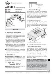
AP04 Software S (Standard) - SIKO Products USA
AP04 Software S (Standard) - SIKO Products USA
AP04 Software S (Standard) - SIKO Products USA

Sie wollen auch ein ePaper? Erhöhen Sie die Reichweite Ihrer Titel.
YUMPU macht aus Druck-PDFs automatisch weboptimierte ePaper, die Google liebt.
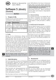
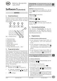
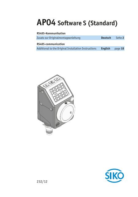
<strong>AP04</strong> <strong>Software</strong> S (<strong>Standard</strong>)<br />
RS485-Kommunikation<br />
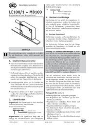
Zusatz zur Originalmontageanleitung Deutsch Seite 2<br />
RS485-communication<br />
Additional to the Original Installation Instructions English page 18<br />
232/12
2<br />
<strong>AP04</strong>-S<br />
Inhaltsverzeichnis<br />
<strong>AP04</strong>-S · Datum 19.07.2012 · Art. Nr. 84599 · Änd. Stand 232/12<br />
Deutsch<br />
1 Dokumentation . . . . . . . . . . . . . . . . . . . . 3<br />
2 Sicherheitshinweise . . . . . . . . . . . . . . . . . . 3<br />
3 Display . . . . . . . . . . . . . . . . . . . . . . . . 3<br />
4 Tastenfunktionen . . . . . . . . . . . . . . . . . . . 3<br />
5 RS485-Schnittstelle . . . . . . . . . . . . . . . . . . 4<br />
6 <strong>SIKO</strong>NETZ 3 . . . . . . . . . . . . . . . . . . . . . . 5<br />
7 <strong>SIKO</strong>NETZ 4 . . . . . . . . . . . . . . . . . . . . . 10<br />
7.1 Status-/ Adresse . . . . . . . . . . . . . . . . . 10<br />
7.2 Datenbytes . . . . . . . . . . . . . . . . . . . . 11<br />
7.3 Prüfsumme . . . . . . . . . . . . . . . . . . . . 13<br />
8 Service-<strong>Standard</strong>-Protokoll . . . . . . . . . . . . . . 14
<strong>AP04</strong>-S<br />
Dokumentation Deutsch<br />
1 Dokumentation<br />
Es gelten weitere Dokumente, siehe Auflistung in der Originalmontageanleitung.<br />
Diese Dokumente sind auch unter "http://www.siko.de/service/downloads/ausgewaehlte-downloads/details/ap04/"<br />
zu finden.<br />
2 Sicherheitshinweise<br />
Es gelten die Sicherheitshinweise der Originalmontageanleitung.<br />
3 Display<br />
2 Zeilen mit jeweils 5 Ziffern in 7 Segmenten.<br />
4 Sonderzeichen: " ", " ", , .<br />
Darstellbarer Zahlenbereich: -19999 bis 99999.<br />
Wird dieser Zahlenbereich überschritten erscheint die Meldung "FULL".<br />
Der Wert steht jedoch zur Übertragung via Schnittstelle zur Verfügung.<br />
Im Normalbetrieb wird in der ersten Zeile der Positions-Istwert, in der<br />
zweiten Zeile der Sollwert angezeigt.<br />
4 Tastenfunktionen<br />
Die <strong>AP04</strong> verfügt über -, - und -Taste, über welche die Geräteparameter<br />
angepasst werden können.<br />
-Taste<br />
Durch betätigen der -Taste wird die Kettenmaß-Funktion ein- bzw. ausgeschaltet.<br />
Im Display wird dabei das Kettenmaßsymbol ein- bzw.<br />
ausgeblendet. Die Kettenmaß-Funktion muss dabei freigegeben sein.<br />
<strong>AP04</strong>-S · Datum 19.07.2012 · Art. Nr. 84599 · Änd. Stand 232/12<br />
3
4<br />
<strong>AP04</strong>-S<br />
RS485-Schnittstelle Deutsch<br />
Während der Konfiguration wird mit der -Taste der aktuelle Wert verändert.<br />
-Taste<br />
Wird die -Taste länger als 5 s betätigt, so wird beim Freigeben der Taste<br />
der aktuelle Positionswert zu Null gesetzt. Die Nullsetzung muss dazu freigegeben<br />
sein.<br />
Positionswert = 0 + Kalibrierwert + Offsetwert<br />
Bei Betätigen der Taste wird in der unteren Zeile "rESEt" angezeigt,<br />
zunächst blinkend, nach Ablauf von 5 s statisch bis die Taste freigegeben<br />
wird.<br />
Während der Konfiguration wird mit der -Taste der aktuelle Wert bestätigt<br />
und zum nächsten Parameter geschaltet.<br />
-Taste<br />
Die -Taste ist mit verschiedenen Funktionen ausgestattet.<br />
Bei Betätigen der -Taste wird die eingestellte Bus-Adresse (im Beispiel<br />
"1") und Baudrate (115.2 kbit/s) angezeigt.<br />
Beispiel: Id 1<br />
1152<br />
Bei einer Betätigung von mehr als 15 s wird die <strong>AP04</strong> in den Konfigurations-Modus<br />
versetzt. Im Display wird dann der erste Menüpunkt der Konfiguration<br />
angezeigt.<br />
5 RS485-Schnittstelle<br />
Über die serielle RS485-Schnittstelle besteht die Möglichkeit, Daten mit<br />
einer übergeordneten Steuerung oder einem PC auszutauschen. Für die<br />
Funktion am Bus ist ein Abschlusswiderstand notwendig (120 Ohm). Dieser<br />
muss am letzten Busteilnehmer zwischen DÜA/TxRx+/CANH und DÜB/<br />
TxRx-/CANL eingesetzt werden. Z. B. <strong>SIKO</strong> Art. BAS-0005.<br />
Zur Kommunikation stehen drei Protokolle zur Verfügung: <strong>SIKO</strong>NETZ 3,<br />
<strong>SIKO</strong>NETZ 4 oder das Service-<strong>Standard</strong>-Protokoll.<br />
Parameter:<br />
<strong>SIKO</strong>NETZ3: 19200 baud, NO parity, 8Bit, 1 Stoppbit, no handshake.<br />
<strong>SIKO</strong>NETZ4: 115200 baud, EVEN parity, 8Bit, 1 Stoppbit, no handshake.<br />
Service-<strong>Standard</strong>-Protokoll: NO parity, 8Bit, 1 Stoppbit, no handshake,<br />
<strong>AP04</strong>-S · Datum 19.07.2012 · Art. Nr. 84599 · Änd. Stand 232/12
<strong>AP04</strong>-S<br />
<strong>SIKO</strong>NETZ 3 Deutsch<br />
Adresse "0", Baudrate des eingestellten <strong>SIKO</strong>NETZ- Protokolls.<br />
Wird die Knoten-Adresse "0" eingestellt, kommuniziert die <strong>AP04</strong> im Service-<strong>Standard</strong>-Protokoll<br />
mit der Baudrate des eingestellten <strong>SIKO</strong>NETZ-Protokolls<br />
und no parity.<br />
Ausgabe: ASCII; HEX<br />
6 <strong>SIKO</strong>NETZ 3<br />
Parameter: 19200 Baud, NO Parity, 8 Bit, 1 Startbit, 1 Stoppbit<br />
Das <strong>SIKO</strong>NETZ3-Protokoll ist als Master-Slave-System aufgebaut, in dem<br />
die <strong>AP04</strong> immer als Slave eingeordnet ist. Es existieren 2 Telegrammlängen:<br />
3 Byte:<br />
Adress-<br />
Byte<br />
6 Byte:<br />
Adress-<br />
Byte<br />
Befehl Prüf-<br />
Byte<br />
Befehl Daten-<br />
Byte<br />
1<br />
Daten-<br />
Byte<br />
2<br />
Daten-<br />
Byte<br />
3<br />
Das Adressbyte setzt sich wie folgt zusammen:<br />
Prüf-<br />
Byte<br />
1 0 A0 A1 A2 A3 A4 0 RR L 1<br />
Start Stopp<br />
Das Prüfbyte wird als Exklusiv-Oder-Verknüpfung der restlichen 2 bzw. 5<br />
Bytes des Telegramms erzeugt.<br />
A0 ... A4: Binärkodierte Adresse 1 ... 31; Adresse 0 definiert für Master<br />
RR: Rundruf-Bit = 1 Befehl gilt für alle Geräte, Geräte antworten nicht<br />
L: Längen-Bit: 1 = Kurztelegramm (3 Byte); 0 = Langtelegramm (6 Byte)<br />
Befehlsliste <strong>SIKO</strong>NETZ3-Protokoll<br />
Spalte Erläuterung<br />
Hex Hexadezimalwert des Befehls<br />
TX Telegrammlänge vom Master an <strong>AP04</strong><br />
RX Telegrammlänge von <strong>AP04</strong> an Master<br />
S Übergebener Parameter wird nichtflüchtig im Gerät gespeichert<br />
<strong>AP04</strong>-S · Datum 19.07.2012 · Art. Nr. 84599 · Änd. Stand 232/12<br />
5
6<br />
<strong>AP04</strong>-S<br />
<strong>SIKO</strong>NETZ 3 Deutsch<br />
Spalte Erläuterung<br />
P Für diesen Befehl ist es notwendig, den Programmiermode einzuschalten<br />
(Bef 0x32; 0x33)<br />
R Dieser Befehl ist rundruffähig<br />
Hex TX RX S P R Funktion<br />
10 3 6 - - - Sollwert auslesen<br />
12 3 6 - - - InPos-Fenster auslesen<br />
13 3 6 - - - Schleifenumkehrpunkt auslesen<br />
16 3 6 - - - Positionswert auslesen<br />
18 3 6 - - - Kalibrierwert auslesen<br />
19 3 6 - - - Offsetwert auslesen<br />
1b 3 6 - - - Gerätekennung auslesen<br />
D-Byte 1: Kennung = 28;<br />
D-Byte 2: <strong>Software</strong>version;<br />
D-Byte 3: Hardwareversion<br />
1c 3 6 - - - Geräteadresse und Nachkommastellen auslesen<br />
D-Byte 1: Adresse;<br />
D-Byte 2: Nachkommastellen;<br />
D-Byte 3: immer 0<br />
1d 3 6 - - - Zählrichtung auslesen<br />
Wert = 0: "auf" (+);<br />
Wert = 1: "ab" (-)<br />
1e 3 6 - - - APU (Anzeige/Umdrehung) auslesen<br />
20 6 6 - - - Sollwert programmieren<br />
22 6 6 S P - InPos-Fenster programmieren<br />
23 6 6 S P - Schleifenumkehrpunkt programmieren<br />
28 6 6 S P - Kalibrierwert programmieren<br />
29 6 6 S P - Offsetwert programmieren<br />
2c 6 6 S P - Nachkommastellen programmieren<br />
D-Byte 1: 0<br />
D-Byte 2: Nachkommastellen<br />
D-Byte 3: 0<br />
2d 6 6 S P - Zählrichtung programmieren<br />
Wert = 0: "entgegen Uhrzeigersinn" (+)<br />
Wert = 1: "im Uhrzeigersinn" (-)<br />
2e 6 6 S P - APU programmieren<br />
32 3 3 - - - Programmiermode Ein<br />
Programmiermode muss "Ein" sein, um verschiedene<br />
Parameter zu programmieren (P)<br />
<strong>AP04</strong>-S · Datum 19.07.2012 · Art. Nr. 84599 · Änd. Stand 232/12
<strong>AP04</strong>-S<br />
<strong>SIKO</strong>NETZ 3 Deutsch<br />
Hex TX RX S P R Funktion<br />
33 3 3 - - - Programmiermode Aus<br />
Default<br />
34 3 3 S P - Kettenmaßfunktion der Taste freigeben<br />
35 3 3 S P - Kettenmaßfunktion der Taste sperren<br />
38 3 6 - - - ADI (Anzeigendivisor) ausgeben<br />
39 6 6 S P - ADI programmieren<br />
0: ADI = 1<br />
1: ADI = 10<br />
2: ADI = 100<br />
3: ADI = 1000<br />
3a 3 6 - - - Systemstatus ausgeben<br />
D-Byte 1:<br />
bit 3 = 1 => Einfrierflag gesetzt<br />
bit 4 = 1 => Kettenmaß freigegeben<br />
bit 5 = 1 => Gerät im Programmierzustand<br />
D-Byte 2: Errorregister<br />
bit 1 = 1 => Datenübertragungsfehler Prüfbyte<br />
bit 2 = 1 => unzulässiger oder unbekannter<br />
Befehl<br />
bit 3 = 1 => unzulässiger Wert<br />
bit 7 = 1 => Batterie leer<br />
D-Byte 3:<br />
bit 0 = 1 => Sollwert wurde erreicht: reset<br />
mit Befehl 3Bh<br />
bit 2 = 1 => Batteriezustand kritisch<br />
bit 3 = 1 => Kettenmaß gesetzt<br />
3b 3 3 - - - Systemstatus löschen; alle Fehlermeldungen<br />
und "Sollwert wurde erreicht"-bit werden<br />
gelöscht<br />
40 6 6 S P - Schleifenrichtung programmieren<br />
Wert = 0: direkt<br />
Wert = 1: im Uhrzeigersinn<br />
Wert = 2: entgegen Uhrzeigersinn<br />
41 3 6 - - - Schleifenrichtung ausgeben<br />
42 6 6 S P - Nullungsfunktion der Taste programmieren<br />
Wert = 0: Nullung gesperrt<br />
Wert = 1: Nullung freigegeben<br />
43 3 6 - - - Nullungsfreigabe auslesen<br />
48 3 3 S P - Positionswert wird auf Kalibrierwert + Offsetwert<br />
gesetzt<br />
<strong>AP04</strong>-S · Datum 19.07.2012 · Art. Nr. 84599 · Änd. Stand 232/12<br />
7
8<br />
<strong>AP04</strong>-S<br />
<strong>SIKO</strong>NETZ 3 Deutsch<br />
Hex TX RX S P R Funktion<br />
4c 6 6 S P - Displayorientierung und LED-Funktionalität<br />
programmieren<br />
D-Byte 1:<br />
Wert = 0: Displayausrichtung 0°<br />
Wert = 1: Displayausrichtung 180°<br />
D-Byte 2:<br />
bit 0 = 1 => LED grün EIN wenn Zielfenster<br />
erreicht<br />
bit 1 = 1 => LED rot EIN wenn außerhalb des<br />
Zielfensters<br />
bit 3 = 1 => LEDs blinken wenn EIN<br />
bit 4 = 1 => LED grün EIN unabhängig vom<br />
Zielfenster<br />
bit 5 = 1 => LED rot EIN unabhängig vom<br />
Zielfenster<br />
Nur die bits 0...3 werden nichtflüchtig<br />
gespeichert. Um bit 4...5 zu setzen, muss<br />
die Zielfensterabhängigkeit (bit 0...1)<br />
deaktiviert sein.<br />
4d 3 6 - - - Displayorientierung und LED-Funktionalität<br />
auslesen<br />
4f 3 3 - - R Positionswert einfrieren<br />
Positionswert wird eingefroren. Zustand<br />
wird durch Auslesen des Positionswertes<br />
zurückgesetzt. Dient zum synchronisierten<br />
Auslesen mehrerer Geräte.<br />
Fehlermeldungen<br />
Der Slave (<strong>AP04</strong>) erkennt Übertragungs- bzw. Eingabefehler und sendet<br />
folgende Fehlermeldungen:<br />
Hex TX RX S P R Funktion<br />
82 - 3 - - - Datenübertragungsfehler Prüfsumme<br />
83 - 3 - - - Unzulässiger oder unbekannter Befehl<br />
85 - 3 - - - Unzulässiger Wert (Parameter Programmierung)<br />
Synchronisation:<br />
Eine Byte-/Telegrammsynchronisation erfolgt über "Timeout": Der<br />
Abstand der einzelnen Bytes eines Telegramms darf einen Wert von 10 ms<br />
nicht übersteigen. Falls ein angesprochenes Gerät nicht antwortet, so darf<br />
der Master frühestens nach 30 ms erneut ein Telegramm senden.<br />
<strong>AP04</strong>-S · Datum 19.07.2012 · Art. Nr. 84599 · Änd. Stand 232/12
<strong>AP04</strong>-S<br />
<strong>SIKO</strong>NETZ 3 Deutsch<br />
Telegrammbeispiel:<br />
Positionswert des Geräts mit Adresse 7 soll ausgegeben werden.<br />
Master sendet (hex): 87 16 91<br />
Kurztelegramm an Adresse 7 (87h); Positionswert auslesen (16h); Prüfbyte<br />
(91h)<br />
<strong>AP04</strong> antwortet (hex): 07 16 03 02 00 10<br />
Langtelegramm von Adresse 7 (07h); Positionswert auslesen (16h); Wert<br />
203h = 515 dez (03 02 00h); Prüfbyte (10h).<br />
Programmiermode ein (ID 1)<br />
81h 32h B3h<br />
Programmiermode ein (ID 7)<br />
87h 32h B5h<br />
Kalibrierwert 0 schreiben (ID 1)<br />
01h 28h 00h 00h 00h 29h<br />
Kalibrierwert 100 schreiben (ID 1)<br />
XOR Prüfsumme = B3h = 81h XOR 32h<br />
Befehl "Programmiermodus EIN"<br />
Längenbit (80h) UND ID 1<br />
XOR Prüfsumme<br />
Befehl "Programmiermodus EIN"<br />
Längenbit (80h) UND ID 7<br />
<strong>AP04</strong>-S · Datum 19.07.2012 · Art. Nr. 84599 · Änd. Stand 232/12<br />
XOR Prüfsumme<br />
Wert = 0<br />
Befehl Kalibrierwert programmieren<br />
Längenbit (00h) UND ID 1<br />
01h 28h 64h 00h 00h 29h<br />
XOR Prüfsumme<br />
Wert = 100<br />
Befehl Kalibrierwert programmieren<br />
Längenbit (00h) UND ID 1<br />
9
10<br />
<strong>AP04</strong>-S<br />
<strong>SIKO</strong>NETZ 4 Deutsch<br />
Positionswert auf Kalibrierwert + Offset zurücksetzen (ID 1)<br />
81h 48h C9h<br />
Programmiermode schließen (ID 1)<br />
81h 33h B2h<br />
Sollwert 123 schreiben (ID 1)<br />
01h 20h 7Bh 00h 00h 5Ah<br />
7 <strong>SIKO</strong>NETZ 4<br />
XOR Prüfsumme<br />
Wert = 123<br />
Befehl Sollwert programmieren<br />
Längenbit (00h) UND ID 1<br />
Busprotokoll für bis zu 31 Teilnehmer.<br />
Parameter: 115200 baud, EVEN parity, 8Bit, 1 Stoppbit, no handshake.<br />
Das Datentelegramm besteht immer aus 5 Bytes:<br />
1. Byte: Status-/ Adresse.<br />
2. Byte: Datenbyte A<br />
3. Byte: Datenbyte B<br />
4. Byte: Datenbyte C<br />
5. Byte: Prüfsumme<br />
7.1 Status-/ Adresse<br />
Dieses Byte definiert die Art des Telegramms, das übermittelt werden soll,<br />
d. h. ob zum Beispiel die Konfiguration der <strong>AP04</strong> geändert werden soll<br />
oder nur der Positionswert ausgelesen wird. Die <strong>AP04</strong> reagiert nur auf<br />
Nachrichten mit der übereinstimmenden Geräteadresse.<br />
<strong>AP04</strong>-S · Datum 19.07.2012 · Art. Nr. 84599 · Änd. Stand 232/12
<strong>AP04</strong>-S<br />
<strong>SIKO</strong>NETZ 4 Deutsch<br />
ACHTUNG<br />
Bit-Nr. Master -> <strong>AP04</strong><br />
7 Bit=1 Wert programmieren<br />
Bit=0 Wert auslesen<br />
6-5 Befehlskodierung<br />
00: Sollwert<br />
01: Kalibrierwert<br />
10: APU (Anzeige/Umdrehung)<br />
11: Status/die Einzelbits (bei diesem Code haben die Datenbytes<br />
eine unterschiedliche Bedeutung!)<br />
4-0 Geräteadresse der <strong>AP04</strong><br />
Bit-Nr. <strong>AP04</strong> -> Master<br />
7 Bit=1 Prüfsummenfehler<br />
Bit=0 Prüfsumme ok<br />
6-5 Befehlskodierung<br />
00: Positionswert<br />
01: Kalibrierwert<br />
10: APU<br />
11: Status/die Einzelbits (bei diesem Code haben die Datenbytes<br />
eine unterschiedliche Bedeutung!)<br />
4-0 Geräteadresse der <strong>AP04</strong><br />
7.2 Datenbytes<br />
Wird im Status-/Adressbyte der Befehlscode in bit 5 und 6 zu "11"<br />
gesetzt, haben die 3 Datenbytes unterschiedliche Bedeutungen!<br />
Die Datenbytes beinhalten die Zahlenwerte für die einzelnen Parameter<br />
die programmiert bzw. abgefragt werden (Positions-, Kalibrier-, Anzeige-<br />
und Sollwert). Die Darstellung erfolgt in hexadezimaler Schreibweise. Zum<br />
Beispiel wird der Wert 1000 folgendermaßen dargestellt:<br />
dezimal: 1000<br />
hexadezimal: 0x0003E8<br />
Datenbyte A Datenbyte B Datenbyte C<br />
00 03 E8<br />
Byte 2 (Datenbyte A):<br />
Versionsnummer (z. B. V1.01 = 0x65).<br />
<strong>AP04</strong>-S · Datum 19.07.2012 · Art. Nr. 84599 · Änd. Stand 232/12<br />
11
12<br />
<strong>AP04</strong>-S<br />
<strong>SIKO</strong>NETZ 4 Deutsch<br />
Byte 3 (Datenbyte B):<br />
Bit-Nr. Verwendung<br />
7-6 Schleifenanfahrrichtung<br />
00 = direkt<br />
01 = im Uhrzeigersinn<br />
10 = entgegen Uhrzeigersinn<br />
5-4 ADI (Anzeigendivisor)<br />
00: 1<br />
01: 10<br />
10: 100<br />
11: 1000<br />
3 Nicht verwendet<br />
2-0 Nachkommastellen<br />
000: 0 = kein Dezimalpunkt<br />
001: 1<br />
010: 2<br />
011: 3<br />
100: 4<br />
Byte 4 (Datenbyte C):<br />
Bit-Nr. Master -> <strong>AP04</strong><br />
7 Displayorientierung<br />
0: 0°<br />
1: 180°<br />
6 Freigabe Tastenfunktion<br />
1: Kettenmaß und Rücksetzen freigegeben<br />
0: Freigabe entsprechend Bits 5-4<br />
5-4 Freigabe Tastenfunktionen<br />
00: keine Tastenfunktionen freigegeben<br />
01: Kettenmaß freigegeben<br />
10: Rücksetzen freigegeben<br />
11: keine Aussage (aus Kompatibilitätsgründen)<br />
3 Rücksetzen<br />
2 Kettenmaß setzen<br />
1 nicht verwendet<br />
0 Drehrichtung<br />
0: entgegen den Uhrzeigersinn<br />
1: im Uhrzeigersinn<br />
<strong>AP04</strong>-S · Datum 19.07.2012 · Art. Nr. 84599 · Änd. Stand 232/12
<strong>AP04</strong>-S<br />
<strong>SIKO</strong>NETZ 4 Deutsch<br />
Bit-Nr. <strong>AP04</strong> -> Master<br />
7 Batterie leer<br />
6 Freigabe Tastenfunktionen<br />
1: Kettenmaß und Rücksetzen freigegeben<br />
0: Freigabe entsprechend Bits 5-4<br />
5-4 Freigabe Tastenfunktionen<br />
00: keine Tastenfunktionen freigegeben<br />
01: Kettenmaß freigegeben<br />
10: Rücksetzen freigegeben<br />
11: keine Aussage (aus Kompatibilitätsgründen)<br />
3 nicht verwendet<br />
2 Displayorientierung<br />
0: 0°<br />
1: 180°<br />
1 nicht verwendet<br />
0 Drehrichtung<br />
0: entgegen den Uhrzeigersinn<br />
1: im Uhrzeigersinn<br />
7.3 Prüfsumme<br />
Zur Überprüfung einer fehlerfreien Datenübertragung wird am Ende des<br />
Telegramms eine Prüfsumme gebildet. Die Prüfsumme ist die Exklusiv-<br />
Oder-Verknüpfung der Bytes 1-4:<br />
Prüfsumme [Byte 5] = [Byte 1] XOR [Byte 2] XOR [Byte 3] XOR [Byte 4]<br />
Zur Überprüfung des empfangenen Telegramms gilt folgendes:<br />
[Byte 1] XOR [Byte 2] XOR [Byte 3] XOR [Byte 4] XOR [Byte 5] = 0<br />
Ist das Ergebnis ungleich 0 ist ein Fehler in der Übertragung zu vermuten.<br />
Synchronisation:<br />
Eine Byte-/Telegrammsynchonisation erfolgt über "Timeout": Der Abstand<br />
der einzelnen Bytes eines Telegramms dürfen einen Wert von 10 ms nicht<br />
übersteigen. Falls ein angesprochenes Gerät nicht antwortet, so darf der<br />
Master frühestens nach 30 ms erneut ein Telegramm senden. Die Speicherung<br />
der nichtflüchtigen Parameter erfordert bis zu 30 ms. Erst nach erfolgreicher<br />
Speicherung erfolgt die Beantwortung des Schreibbefehls.<br />
Beispiele:<br />
a) Auslesen des Positionswertes einer <strong>AP04</strong> mit Adresse 12 (z. B. Positionswert<br />
= 2045,6 (4FE8 hex).<br />
<strong>AP04</strong>-S · Datum 19.07.2012 · Art. Nr. 84599 · Änd. Stand 232/12<br />
13
14<br />
<strong>AP04</strong>-S<br />
Service-<strong>Standard</strong>-Protokoll Deutsch<br />
Master -> <strong>AP04</strong> <strong>AP04</strong> -> Master<br />
1. Byte 0000 1100 (OC) 0000 0000 (00)<br />
2. Byte 0000 0000 (00) 0000 0000 (00)<br />
3. Byte 0000 0000 (00) 0100 1111 (4F)<br />
4. Byte 0000 0000 (00) 1110 1000 (E8)<br />
5. Byte 0000 1100 (OC) 1010 0111 (A7)<br />
b) Auslesen der Konfiguration einer <strong>AP04</strong> mit Adresse 12.<br />
Schleifenanfahrrichtung direkt<br />
Anzeigendivisor 1<br />
Nachkommastellen 1<br />
Displayausrichtung 180°<br />
Tastenfunktion nur Rücksetzen freigegeben<br />
Drehrichtung entgegen Uhrzeigersinn<br />
<strong>Software</strong> V0.07<br />
Master -> <strong>AP04</strong> <strong>AP04</strong> -> Master<br />
1. Byte 0110 1100 (6C) 0110 1100 (6C)<br />
2. Byte 0000 0000 (00) 0000 0111 (07)<br />
3. Byte 0000 0001 (01) 0000 0001 (01)<br />
4. Byte 1010 0000 (A0) 0010 0100 (24)<br />
5. Byte 1100 1101 (CD) 0100 1110 (4E)<br />
c) Kalibrierwert programmieren auf Adresse 3 (z. B. Kalibrierwert= -100<br />
(FF FF 9C hex;) <strong>AP04</strong> quittiert mit Wert -100)<br />
Master -> <strong>AP04</strong> <strong>AP04</strong> -> Master<br />
1. Byte 1010 0011 (A3) 0010 0011 (23)<br />
2. Byte 1111 1111 (FF) 1111 1111 (FF)<br />
3. Byte 1111 1111 (FF) 1111 1111 (FF)<br />
4. Byte 1001 1100 (9C) 1001 1100 (9C)<br />
5. Byte 0011 1111 (3F) 1011 1111 (BF)<br />
8 Service-<strong>Standard</strong>-Protokoll<br />
Die <strong>AP04</strong> kommuniziert nach dem Service-<strong>Standard</strong>-Protokoll sobald die<br />
Adresse "0" eingestellt wird. Nach einem Neustart, auch über K-Befehl<br />
(Warmstart), ist wieder die ursprüngliche Geräteadresse für <strong>SIKO</strong>NETZ X<br />
aktiv. Die Baudrate wird ebenso von der <strong>SIKO</strong>NETZ X-Einstellung übernommen.<br />
<strong>AP04</strong>-S · Datum 19.07.2012 · Art. Nr. 84599 · Änd. Stand 232/12
<strong>AP04</strong>-S<br />
Service-<strong>Standard</strong>-Protokoll Deutsch<br />
Parameter: no Parity, 8 Bit, 1 Startbit, 1 Stoppbit<br />
<strong>SIKO</strong>NETZ 3: Baudrate 19200<br />
<strong>SIKO</strong>NETZ 4: Baudrate 115200<br />
Das Service-<strong>Standard</strong>-Protokoll ist nach folgendem Prinzip aufgebaut:<br />
Die Steuerung (PC) sendet einen Buchstaben (ASCII); falls erforderlich<br />
mit zusätzlichen Parametern. Die <strong>AP04</strong> sendet daraufhin eine Antwort<br />
mit abschließendem CR (0x0D). Es werden große und kleine Buchstaben<br />
akzeptiert (ASCII).<br />
Befehlsliste<br />
Befehl Zugriff Daten Zeichen- Antwort<br />
anzahl<br />
Bedeutung Beispiel<br />
A0 read 2/7 "HWVxxxx>" Versionsnummer Hardware V002<br />
A1 read 2/7 "SWVxxxx>" Versionsnummer <strong>Software</strong> V006<br />
B read 1/10 "+xxxxxxxx>" Positionswert ohne Korrekturwerte<br />
C x/1 "?"<br />
D x/1 "?"<br />
<strong>AP04</strong>-S · Datum 19.07.2012 · Art. Nr. 84599 · Änd. Stand 232/12<br />
+00000016<br />
E0 read 2/10 "+xxxxxxxx>" Positionswert +00000023<br />
E1 read 2/10 "+xxxxxxxx>" Kalibrierwert +00000004<br />
E2 read 2/10 "+xxxxxxxx>" Offset +00000003<br />
E3 read 2/10 "+xxxxxxxx>" Kettenmaß +00000000<br />
E4 read 2/10 "+xxxxxxxx>" Positionswert bei Nullung +00000000<br />
E5 read 2/10 "+xxxxxxxx>" Abweichungsfenster (InPos) +00000005<br />
E6 read 2/10 "+xxxxxxxx>" Umkehrpunkt für Schleife +00000000<br />
E7 read 2/10 "+xxxxxxxx>" APU (Anzeige pro Umdrehung) +00000720<br />
E8 read 2/10 "+xxxxxxxx>" ADI (Anzeigendivisor) +00000001<br />
F1 write "+/-xxxxxxxx" 9/1 ">" Kalibrierwert F1+00000004<br />
F2 write "+/-xxxxxxxx" 9/1 ">" Offset F2+00000003<br />
F5 write "+/-xxxxxxxx" 9/1 ">" InPos-Fenster F5+00000005<br />
F6 write "+/-xxxxxxxx" 9/1 ">" Umkehrpunkt für Schleife F6+00000000<br />
F7 write "+/-xxxxxxxx" 9/1 ">" APU F7+00000720<br />
F8 write "+/-xxxxxxxx" 9/1 ">" ADI F8+00000003<br />
G x/1 "?"<br />
H x/1 "?"<br />
lab write<br />
write<br />
write<br />
write<br />
"1x"<br />
"0x"<br />
"x1"<br />
"x0"<br />
3/1<br />
3/1<br />
3/1<br />
3/1<br />
">"<br />
">"<br />
">"<br />
">"<br />
a = 1: Nullung freigeben<br />
a = 0: Nullung gesperrt<br />
b = 1: Kettenmaß setzen freigegeben<br />
b = 0: Kettenmaß setzen<br />
gesperrt<br />
I11<br />
I01<br />
I11<br />
I10<br />
15
16<br />
<strong>AP04</strong>-S<br />
Service-<strong>Standard</strong>-Protokoll Deutsch<br />
Befehl Zugriff Daten Zeichenanzahl<br />
Jab write "Ex"<br />
3/1<br />
write<br />
write<br />
write<br />
write<br />
"Ix"<br />
"0x"<br />
"x0"<br />
"x1"<br />
3/1<br />
3/1<br />
3/1<br />
3/1<br />
Antwort Bedeutung Beispiel<br />
">"<br />
">"<br />
">"<br />
">"<br />
">"<br />
a = E: Anfahrrichtung bei<br />
Schleife entgegen dem Uhrzeigersinn<br />
a = I: im Uhrzeigersinn<br />
a = 0: Direkt<br />
b = 0: Display Orientierung 0°<br />
b = 1: Display Orientierung<br />
180°<br />
K write 1/1 ">" Warmstart K<br />
L write 1/1 ">" Positionswert rücksetzen L<br />
M write 1/3 "xx>" Busadresse für <strong>SIKO</strong>NETZ X<br />
lesen<br />
M<br />
N write "xx" 3/1 ">" Busadresse für <strong>SIKO</strong>NETZ X<br />
schreiben<br />
N01<br />
O0 read "0" 2/8 "RES xxx>" Lesen der Freigabe Nullung RES en<br />
O1 read "1" 2/8 "KET xxx>" Lesen der Freigabe Kettenmaß<br />
setzen<br />
KET dis<br />
P0 read 2/6 "DIR x>" Drehrichtung lesen DIR E<br />
<strong>AP04</strong>-S · Datum 19.07.2012 · Art. Nr. 84599 · Änd. Stand 232/12<br />
JE0<br />
JI0<br />
J00<br />
JE0<br />
JE1<br />
P1 read 2/7 "LOOP x>" Schleifenanfahrrichtung lesen LOOP D<br />
P2 read 2/10 "DISP xxx°" Displayorientierung lesen DISP 180°<br />
P3 read 2/17 "LED Gx Rx Fx<br />
Cxx>"<br />
LED-Funktionalität lesen LED G1 R0 F1<br />
C00 = Grün<br />
EIN, Rot AUS,<br />
Flash EIN,<br />
Konstant<br />
beide AUS<br />
Q1x write "x" 3/1 ">" grüne LED-Funktionalität<br />
schreiben<br />
x = 0 AUS<br />
x = 1 Zielfenster<br />
x = 2 Dauer (konstant)<br />
Q2x write "x" 3/1 ">" rote LED-Funktionalität schreiben<br />
x = 0 AUS<br />
x = 1 Zielfenster<br />
x = 2 Dauer (konstant)<br />
Q4x write "x" 3/1 ">" LED-Blinken schreiben<br />
x = 0 AUS<br />
x = 1 EIN<br />
R read 1/1 "x" Status-Register<br />
S write<br />
write<br />
"11100"<br />
"00100"<br />
6/1<br />
6/1<br />
">"<br />
">"<br />
Werkseinstellungen wiederherstellen<br />
Abgleichfahrt durchführen<br />
Q11 = grün<br />
EIN bei Zielfenster<br />
erreicht<br />
Q20 = rot AUS<br />
Q41 = Blinken<br />
EIN
<strong>AP04</strong>-S<br />
Service-<strong>Standard</strong>-Protokoll Deutsch<br />
Befehl Zugriff Daten Zeichen- Antwort<br />
anzahl<br />
Bedeutung Beispiel<br />
Ta write "I"<br />
2/1 ">"<br />
Drehrichtung im Uhrzeigersinn<br />
Drehrichtung entg. Uhrzei-<br />
write "E"<br />
2/1 ">"<br />
gersinn<br />
U read 1/10 "xxxxxxxxxx" Ausgabe der Grobwerte<br />
V read 1/5 "x,xV>" Ausgabe der Batteriespannung 3,0V<br />
W read 1/4 "xxxx" Ausgabe des Positionswertes<br />
in hex<br />
X write "+/-xxxxx" 7/1 ">" Eingabe Sollwert dez., 5 stellig,<br />
mit Vorzeichen<br />
X+00150<br />
Y read 1/10 "xxxxxxxx>" Ausgabe Sollwert +00000150<br />
Z read 1/10 "xxxxxxxx>" Ausgabe Positionswert -00000150<br />
<strong>AP04</strong>-S · Datum 19.07.2012 · Art. Nr. 84599 · Änd. Stand 232/12<br />
17
18<br />
<strong>AP04</strong>-S<br />
Table of contents<br />
<strong>AP04</strong>-S · Date 19.07.2012 · Art. No. 84599 · Mod. status 232/12<br />
English<br />
1 Documentation . . . . . . . . . . . . . . . . . . . 19<br />
2 Safety information . . . . . . . . . . . . . . . . . . 19<br />
3 Display . . . . . . . . . . . . . . . . . . . . . . . 19<br />
4 Keys' function . . . . . . . . . . . . . . . . . . . . 19<br />
5 RS485 interface . . . . . . . . . . . . . . . . . . . 20<br />
6 <strong>SIKO</strong>NETZ 3 . . . . . . . . . . . . . . . . . . . . . 21<br />
7 <strong>SIKO</strong>NETZ 4 . . . . . . . . . . . . . . . . . . . . . 26<br />
7.1 Status-/ adresse . . . . . . . . . . . . . . . . . 26<br />
7.2 Datenbytes . . . . . . . . . . . . . . . . . . . . 27<br />
7.3 Check sum . . . . . . . . . . . . . . . . . . . . 29<br />
8 Service-<strong>Standard</strong>-Protocol . . . . . . . . . . . . . . 30
<strong>AP04</strong>-S<br />
Documentation English<br />
1 Documentation<br />
There are further relevant documents - see list in original installation instruction.<br />
These documents can also be downloaded at "http://www.siko.de/en/<br />
service/downloads/selected-downloads/details/ap04/".<br />
2 Safety information<br />
Saftey information of original installation instruction apply.<br />
3 Display<br />
2 lines with each 5 digits in 7 segments.<br />
4 special characters: " ", " ", , .<br />
Displayable number range: -19999 to 99999.<br />
If this number range is exceeded, a "FULL" message will be displayed.<br />
However, the value will be available for transfer via interface.<br />
In normal mode first display line shows actual position value and second<br />
line target value.<br />
4 Keys' function<br />
The <strong>AP04</strong> has the , and keys, which serve for device parameter<br />
adjustment.<br />
key<br />
By pressing the key, the incremental measurement function is switched<br />
on or off. During this action, the incremental measurement symbol<br />
is shown or hidden on the display. The incremental measurement function<br />
must be enabled before switching between the functions.<br />
<strong>AP04</strong>-S · Date 19.07.2012 · Art. No. 84599 · Mod. status 232/12<br />
19
20<br />
<strong>AP04</strong>-S<br />
RS485 interface English<br />
During configuration, the current value can be changed by means of the<br />
key.<br />
key<br />
If the key is pressed for more than 5 s, then the current position value<br />
is zeroed after releasing the key. For doing this, zeroing must be enabled.<br />
Position value = 0 + calibration value + offset value<br />
Upon pressing the button, "rESEt" will be displayed blinking in the lower<br />
line for 5 s and statically afterwards until after releasing the button.<br />
During configuration the key serves for acknowledging the current<br />
value and switching over to the next parameter.<br />
key<br />
The has various functions.<br />
By pressing the key, the set bus address ("1" in the example) and baud<br />
rate (115.2 kbit/s) will be displayed.<br />
Example: Id 1<br />
1152<br />
When actived during more than 15 s, <strong>AP04</strong> will switch to configuration<br />
mode. Display will then show the first configuration menu point.<br />
5 RS485 interface<br />
The serial RS485 interface makes possible the exchange of data with an<br />
upstream control or PC. For bus operation a terminating resistor (120 Ohm)<br />
e. g. <strong>SIKO</strong> type BAS-0005 must be used and mounted at the last bus device<br />
between DÜA/TxRx+/CANH and DÜB/TxRx-/CANL.<br />
Three protocols can be used for communication: <strong>SIKO</strong>NETZ 3, <strong>SIKO</strong>NETZ 4<br />
or the Service <strong>Standard</strong> protocol.<br />
Parameter:<br />
<strong>SIKO</strong>NETZ3: 19200 baud, NO parity, 8Bit, 1 Stoppbit, no handshake.<br />
<strong>SIKO</strong>NETZ4: 115200 baud, EVEN parity, 8Bit, 1 Stoppbit, no handshake.<br />
Service-<strong>Standard</strong>-Protocol: address "0", baud rate of the adjusted <strong>SIKO</strong>-<br />
NETZ- protocol, NO parity, 8Bit, 1 Stop bit, no handshake.<br />
If the address "0" is set, the <strong>AP04</strong> communicates in the Service <strong>Standard</strong><br />
protocol. The baud rate is given by the adjusted <strong>SIKO</strong>NETZ protocol and<br />
without parity.<br />
<strong>AP04</strong>-S · Date 19.07.2012 · Art. No. 84599 · Mod. status 232/12
<strong>AP04</strong>-S<br />
<strong>SIKO</strong>NETZ 3 English<br />
Output: ASCII; HEX<br />
6 <strong>SIKO</strong>NETZ 3<br />
Parameter: 19200 Baud, NO parity, 8 Bit, 1 Startbit, 1 Stoppbit<br />
The <strong>SIKO</strong>NETZ3 protocol is build as a master-slave-system where the <strong>AP04</strong><br />
is always a slave. There are two different lengths of telegrams:<br />
3 Byte:<br />
addressbyte<br />
6 Byte:<br />
addressbyte<br />
command checkbyte<br />
command databyte<br />
1<br />
databyte<br />
2<br />
The adress byte is build as follows:<br />
databyte<br />
3<br />
checkbyte<br />
1 0 A0 A1 A2 A3 A4 0 RR L 1<br />
start stopp<br />
The check byte is build with an EXOR-junction of the other 2 respective 5<br />
bytes in the telegram.<br />
A0 … A4: binary coded address 1 … 31, address 0 is defined for master.<br />
RR: broadcast bit = 1 command is valid for all devices, there will be no<br />
answer to this command.<br />
L: length bit: 1 = short telegram (3 byte); 0 = long telegram (6 byte)<br />
Command list <strong>SIKO</strong>NETZ3-protocol<br />
column meanings<br />
Hex Hexadecimal value of the command<br />
TX Length of the telegram, master to <strong>AP04</strong><br />
RX Length of the telegram, <strong>AP04</strong> to master<br />
S Sent parameter is saved nonvolatile in the device<br />
P For this commend it is necessary to bring the device into the<br />
program mode (command 0x32; 0x33)<br />
R Broadcast command<br />
<strong>AP04</strong>-S · Date 19.07.2012 · Art. No. 84599 · Mod. status 232/12<br />
21
22<br />
<strong>AP04</strong>-S<br />
<strong>SIKO</strong>NETZ 3 English<br />
Hex TX RX S P R Function<br />
10 3 6 - - - read target value<br />
12 3 6 - - - read InPos window<br />
13 3 6 - - - read reversal point for loop<br />
16 3 6 - - - read position value<br />
18 3 6 - - - read calibration value<br />
19 3 6 - - - read offset value<br />
1b 3 6 - - - Read device identification<br />
D-Byte 1: identification = 28;<br />
D-Byte 2: software version;<br />
D-Byte 3: hardware version<br />
1c 3 6 - - - Read device address and decimal places<br />
D-Byte 1: address;<br />
D-Byte 2: decimal places;<br />
D-Byte 3: always 0<br />
1d 3 6 - - - read sense of rotation<br />
value = 0: "ccw" (+);<br />
value = 1: "cw" (-)<br />
1e 3 6 - - - Read display / revolution<br />
20 6 6 - - - Write target value<br />
22 6 6 S P - Write InPos-window<br />
23 6 6 S P - Write Reversal point for loop<br />
28 6 6 S P - Write calibration value<br />
29 6 6 S P - Write offset value<br />
2c 6 6 S P - Write decimal places<br />
D-Byte 1: 0<br />
D-Byte 2: decimal places<br />
D-Byte 3: 0<br />
2d 6 6 S P - Write sense of rotation<br />
value = 0: "ccw" (+)<br />
value = 1: "cw" (-)<br />
2e 6 6 S P - Write APU<br />
32 3 3 - - - program mode "ON"<br />
Program mode must be ON to write several<br />
parameters. (P)<br />
33 3 3 - - - Program mode "OFF"<br />
Default<br />
34 3 3 S P - incremental measurement function enabled<br />
35 3 3 S P - incremental measurement function disabled<br />
38 3 6 - - - Read ADI<br />
<strong>AP04</strong>-S · Date 19.07.2012 · Art. No. 84599 · Mod. status 232/12
<strong>AP04</strong>-S<br />
<strong>SIKO</strong>NETZ 3 English<br />
Hex TX RX S P R Function<br />
39 6 6 S P - Write ADI<br />
0: ADI = 1<br />
1: ADI = 10<br />
2: ADI = 100<br />
3: ADI = 1000<br />
3a 3 6 - - - Read system status<br />
D-Byte 1:<br />
bit 3 = 1 => activation freeze flag<br />
bit 4 = 1 => release incremental measurement<br />
function<br />
bit 5 = 1 => device in programming mode<br />
D-Byte 2: error register<br />
bit 1 = 1 => Data transmit error check<br />
bit 2 = 1 => illegal or unknown command<br />
bit 3 = 1 => illegal value<br />
bit 7 = 1 => Battery empty<br />
D-Byte 3:<br />
bit 0 = 1 => target value reached: reset via<br />
command 3Bh<br />
bit 2 = 1 => critical battery status<br />
bit 3 = 1 => activation of incremental measurement<br />
function<br />
3b 3 3 - - - Delete system status; all error messages<br />
and "target value reached"-bit will be<br />
deleted.<br />
40 6 6 S P - Write loop direction<br />
value = 0: direct<br />
value = 1: "cw"<br />
value = 2: "ccw"<br />
41 3 6 - - - Read loop direction<br />
42 6 6 S P - Write reset function of the key<br />
value = 0: reset disabled<br />
value = 1: reset enabled<br />
43 3 6 - - - Read reset function<br />
48 3 3 S P - Reset: position value is set to 0 + calibration<br />
value + offset value<br />
<strong>AP04</strong>-S · Date 19.07.2012 · Art. No. 84599 · Mod. status 232/12<br />
23
24<br />
<strong>AP04</strong>-S<br />
<strong>SIKO</strong>NETZ 3 English<br />
Hex TX RX S P R Function<br />
4c 6 6 S P - Program display orientation and LED functionality<br />
D-Byte 1:<br />
value = 0: display orientation 0°<br />
value = 1: display orientation 180°<br />
D-Byte 2:<br />
bit 0 = 1 => LED geen ON when target window<br />
reached<br />
bit 1 = 1 => LED red ON when outside the<br />
target window<br />
bit 3 = 1 => LEDs blink when ON<br />
bit 4 = 1 => LED green ON independent of<br />
target window<br />
bit 5 = 1 => LED red ON independent of target<br />
window<br />
Only bits 0...3 are saved non-volatilely For<br />
setting bits 4...5, target window dependence<br />
(bit 0...1) must be deactivated.<br />
4d 3 6 - - - Read display orientation and LED functionality<br />
4f 3 3 - - R Freeze position value<br />
Position value is frozen. This state is reset<br />
by reading the position value. With this<br />
feature it is possible to read out several<br />
devices synchronized.<br />
Error messages<br />
The slave (<strong>AP04</strong>) detects errors and sends the following messages:<br />
Hex TX RX S P R Function<br />
82 - 3 - - - Data transmission error checksum<br />
83 - 3 - - - Unknown or forbidden command<br />
85 - 3 - - - Forbidden value (parameter programming)<br />
Synchronization:<br />
The synchronization of a byte or a telegram is established by a "timeout":<br />
The time between the several bytes of an telegram must not exceed the<br />
value of 10 ms. If a device is not answering, the master may not send the<br />
next telegram before waiting of 30 ms.<br />
<strong>AP04</strong>-S · Date 19.07.2012 · Art. No. 84599 · Mod. status 232/12
<strong>AP04</strong>-S<br />
<strong>SIKO</strong>NETZ 3 English<br />
Example of a telegram:<br />
The position value of the device at address 7 shall be read.<br />
Master sends (hex): 87 16 91<br />
Short telegram to address 7 (87h); read position value (16h); check byte<br />
(91h)<br />
<strong>AP04</strong> answers (hex): 07 16 03 02 00 10<br />
long telegram from address 7 (07h); read position value (16h); value 203h<br />
= 515 dec (03 02 00h); check byte (10h).<br />
Program mode "ON" (ID 1)<br />
81h 32h B3h<br />
Program mode "ON" (ID 7)<br />
87h 32h B5h<br />
Write calibration value 0 (ID 1)<br />
XOR checksum = B3h = 81h XOR 32h<br />
Command "Program mode ON"<br />
Length bit (80h) UND ID 1<br />
XOR checksum<br />
Command "Program mode ON"<br />
Length bit (80h) UND ID 7<br />
01h 28h 00h 00h 00h 29h<br />
XOR checksum<br />
Value = 0<br />
Command write calibration value<br />
Length bit (00h) UND ID 1<br />
Write calibration value 100 (ID 1)<br />
01h 28h 64h 00h 00h 29h<br />
XOR checksum<br />
Value = 100<br />
Command write calibration value<br />
Length bit (00h) UND ID 1<br />
<strong>AP04</strong>-S · Date 19.07.2012 · Art. No. 84599 · Mod. status 232/12<br />
25
26<br />
<strong>AP04</strong>-S<br />
<strong>SIKO</strong>NETZ 4 English<br />
Reset position value to 0 + calibration value + offset value (ID 1)<br />
81h 48h C9h<br />
Program mode "OFF" (ID 1)<br />
81h 33h B2h<br />
Write target value 123 (ID 1)<br />
01h 20h 7Bh 00h 00h 5Ah<br />
7 <strong>SIKO</strong>NETZ 4<br />
XOR checksum<br />
Value = 123<br />
Command write target value<br />
Length bit (00h) UND ID 1<br />
Bus protocol for up to 31 subscribers.<br />
Parameter: 115200 baud, EVEN parity, 8 Bit, 1 Stoppbit, no handshake.<br />
The data telegram consists always of 5 bytes:<br />
1. byte : status/ address.<br />
2. byte : data byte A<br />
3. byte : data byte B<br />
4. byte : data byte C<br />
5. byte : check sum<br />
7.1 Status-/ adresse<br />
This byte defines the type of telegram to be transmitted, e. g., whether<br />
the configuration of the <strong>AP04</strong> is to be changed or only the position value<br />
read out. The <strong>AP04</strong> responds only to messages with the matching device<br />
address.<br />
<strong>AP04</strong>-S · Date 19.07.2012 · Art. No. 84599 · Mod. status 232/12
<strong>AP04</strong>-S<br />
<strong>SIKO</strong>NETZ 4 English<br />
NOTICE<br />
Bit no. Master -> <strong>AP04</strong><br />
7 Bit=1 program value<br />
Bit=0 read out value<br />
6-5 Command coding<br />
00: setpoint<br />
01: calibration value<br />
10: display / revolution<br />
11: status / the individual bits (the data bytes have different<br />
meanings with this code!)<br />
4-0 Device address of <strong>AP04</strong><br />
Bit no. <strong>AP04</strong> -> Master<br />
7 Bit=1 check sum error<br />
Bit=0 check sum ok<br />
6-5 Command coding<br />
00: position value<br />
01: calibration value<br />
10: display / revolution<br />
11: status / the individual bits (the data bytes have different<br />
meanings with this code!)<br />
4-0 Device address of <strong>AP04</strong><br />
7.2 Datenbytes<br />
The 3 data bytes have different meanings if the command code in bits 5<br />
and 6 is set to "11" in the status / address byte!<br />
The data bytes contain the numerical values for the individual parameters<br />
to be programmed or read (positions, calibration, display and setpoint<br />
values). They are indicated in hexadecimal notation. Example: value 1000<br />
is represented as follows:<br />
dezimal : 1000<br />
hexadezimal: 0x0003E8<br />
Data byte A Data byte B Data byte C<br />
00 03 E8<br />
Byte 2 (Data byte A):<br />
Version number (e. g., V1.01 = 0x65).<br />
<strong>AP04</strong>-S · Date 19.07.2012 · Art. No. 84599 · Mod. status 232/12<br />
27
28<br />
<strong>AP04</strong>-S<br />
<strong>SIKO</strong>NETZ 4 English<br />
Byte 3 (Datenbyte B):<br />
Bit no. Application<br />
7-6 Loop approach direction<br />
00 = direct<br />
01 = "cw"<br />
10 = "ccw"<br />
5-4 Display divisor<br />
00: 1<br />
01: 10<br />
10: 100<br />
11: 1000<br />
3 Not used<br />
2-0 Decimal places<br />
000: 0 = no decimal point<br />
001: 1<br />
010: 2<br />
011: 3<br />
100: 4<br />
Byte 4 (Datenbyte C):<br />
Bit no. Master -> <strong>AP04</strong><br />
7 Display orientation<br />
0: 0°<br />
1: 180°<br />
6 Key functions enable<br />
1: incremental measurement and reset enabled<br />
0: enabling corresponding to bit 5–4<br />
5-4 Key functions enable<br />
00: no key function enabled<br />
01: incremental measurement enabled<br />
10: reset enabled<br />
11: no statement (for compatibility reasons)<br />
3 Reset<br />
2 Set incremental measurement<br />
1 Not used<br />
0 Sense of rotation<br />
0: counter-clockwise<br />
1: clockwise<br />
<strong>AP04</strong>-S · Date 19.07.2012 · Art. No. 84599 · Mod. status 232/12
<strong>AP04</strong>-S<br />
<strong>SIKO</strong>NETZ 4 English<br />
Bit no. <strong>AP04</strong> -> Master<br />
7 Battery empty<br />
6 Key functions enable<br />
1: incremental measurement and reset enabled<br />
0: enabling corresponding to bit 5–4<br />
5-4 Enable status of key functions<br />
00: no key function enabled<br />
01: incremental measurement enabled<br />
10: reset enabled<br />
11: no statement (for compatibility reasons)<br />
3 Not used<br />
2 Display orientation<br />
0: 0°<br />
1: 180°<br />
1 Not used<br />
0 Sense of rotation<br />
0: counter-clockwise<br />
1: clockwise<br />
7.3 Check sum<br />
For checking error-free data transfer, a check sum is formed at the end of<br />
the telegram. The check sum is the anticoincidence of Bytes 1-4:<br />
check sum[Byte 5] = [Byte 1] XOR [Byte 2] XOR [Byte 3] XOR [Byte 4]<br />
The following applies for checking the telegram received:<br />
[Byte 1] XOR [Byte 2] XOR [Byte 3] XOR [Byte 4] XOR [Byte 5] = 0<br />
A transmission error should be suspected if the result is nonzero.<br />
Synchronization:<br />
The synchronization of a byte or a telegram is established by a "timeout":<br />
The time between the several bytes of an telegram must not exceed the<br />
value of 10 ms. If a device is not answering, the master may not send the<br />
next telegram before waiting of 30 ms. Storing the non-volatile parameters<br />
takes up to 30 ms. Only after successfull storing the write command is<br />
answered.<br />
Examples:<br />
a) Reading out the position value of an <strong>AP04</strong> device with address 12 (e. g.<br />
position value = 2045.6 (4FE8 hex).<br />
<strong>AP04</strong>-S · Date 19.07.2012 · Art. No. 84599 · Mod. status 232/12<br />
29
30<br />
<strong>AP04</strong>-S<br />
Service-<strong>Standard</strong>-Protocol English<br />
Master -> <strong>AP04</strong> <strong>AP04</strong> -> Master<br />
1. byte 0000 1100 (OC) 0000 0000 (00)<br />
2. byte 0000 0000 (00) 0000 0000 (00)<br />
3. byte 0000 0000 (00) 0100 1111 (4F)<br />
4. byte 0000 0000 (00) 1110 1000 (E8)<br />
5. byte 0000 1100 (OC) 1010 0111 (A7)<br />
b) Reading out the configuration of an <strong>AP04</strong> device with address 12.<br />
Loop approach direction direct<br />
Display divisor 1<br />
Decimal places 1<br />
Display orientation 180°<br />
Key function release resetting only<br />
Sense of rotation counter clockwise<br />
<strong>Software</strong> V0.07<br />
Master -> <strong>AP04</strong> <strong>AP04</strong> -> Master<br />
1. byte 0110 1100 (6C) 0110 1100 (6C)<br />
2. byte 0000 0000 (00) 0000 0111 (07)<br />
3. byte 0000 0001 (01) 0000 0001 (01)<br />
4. byte 1010 0000 (A0) 0010 0100 (24)<br />
5. byte 1100 1101 (CD) 0100 1110 (4E)<br />
c) Program calibration value to address 3 (e. g., calibration value = -100<br />
(FF FF 9C hex; <strong>AP04</strong> acknowledges with value -100).<br />
Master -> <strong>AP04</strong> <strong>AP04</strong> -> Master<br />
1. byte 1010 0011 (A3) 0010 0011 (23)<br />
2. byte 1111 1111 (FF) 1111 1111 (FF)<br />
3. byte 1111 1111 (FF) 1111 1111 (FF)<br />
4. byte 1001 1100 (9C) 1001 1100 (9C)<br />
5. byte 0011 1111 (3F) 1011 1111 (BF)<br />
8 Service-<strong>Standard</strong>-Protocol<br />
<strong>AP04</strong> communication is based on the Service <strong>Standard</strong> Protocol as soon as<br />
address "0" is set. Following restart, also via the K command, the original<br />
device address for <strong>SIKO</strong>NETZ X will be active again. The baud rate will be<br />
also set by the <strong>SIKO</strong>NETZ X-setting.<br />
Parameter: no Parity, 8 Bit, 1 Startbit, 1 Stoppbit<br />
<strong>AP04</strong>-S · Date 19.07.2012 · Art. No. 84599 · Mod. status 232/12
<strong>AP04</strong>-S<br />
Service-<strong>Standard</strong>-Protocol English<br />
Command<br />
<strong>SIKO</strong>NETZ 3: baud rate 19200<br />
<strong>SIKO</strong>NETZ 4: baud rate 115200<br />
Generally, transmission occurs as follows: The control (PC) sends a letter<br />
(ASCII), with additional parameters if required. Subsequently, the <strong>AP04</strong><br />
sends a response with a concluding CR (0x0D). Small letters and capitals<br />
are accepted equally (ASCII).<br />
List of commands<br />
Access Data Data<br />
quantity<br />
Response Meaning Example<br />
A0 read 2/7 "HWVxxxx>" Hardware version number V002<br />
A1 read 2/7 "SWVxxxx>" <strong>Software</strong> version number V006<br />
B read 1/10 "+xxxxxxxx>" Position value without correction<br />
values<br />
C x/1 "?"<br />
D x/1 "?"<br />
<strong>AP04</strong>-S · Date 19.07.2012 · Art. No. 84599 · Mod. status 232/12<br />
+00000016<br />
E0 read 2/10 "+xxxxxxxx>" Position value +00000023<br />
E1 read 2/10 "+xxxxxxxx>" Calibration value +00000004<br />
E2 read 2/10 "+xxxxxxxx>" Offset +00000003<br />
E3 read 2/10 "+xxxxxxxx>" Incremental measurement +00000000<br />
E4 read 2/10 "+xxxxxxxx>" Position value with zeroing +00000000<br />
E5 read 2/10 "+xxxxxxxx>" InPos window +00000005<br />
E6 read 2/10 "+xxxxxxxx>" Reversal point for loop +00000000<br />
E7 read 2/10 "+xxxxxxxx>" Display per revolution +00000720<br />
E8 read 2/10 "+xxxxxxxx>" Display divisor +00000001<br />
F1 write "+/-xxxxxxxx" 9/1 ">" Calibration value F1+00000004<br />
F2 write "+/-xxxxxxxx" 9/1 ">" Offset F2+00000003<br />
F5 write "+/-xxxxxxxx" 9/1 ">" InPos window F5+00000005<br />
F6 write "+/-xxxxxxxx" 9/1 ">" Reversal point for loop F6+00000000<br />
F7 write "+/-xxxxxxxx" 9/1 ">" APU F7+00000720<br />
F8 write "+/-xxxxxxxx" 9/1 ">" ADI F8+00000003<br />
G x/1 "?"<br />
H x/1 "?"<br />
lab write<br />
write<br />
write<br />
write<br />
"1x"<br />
"0x"<br />
"x1"<br />
"x0"<br />
3/1<br />
3/1<br />
3/1<br />
3/1<br />
">"<br />
">"<br />
">"<br />
">"<br />
a = 1: enable zeroing<br />
a = 0: disabled zeroing<br />
b = 1: enabled incremental<br />
measur. setting<br />
b = 0: disabled increm. measur.<br />
setting<br />
I11<br />
I01<br />
I11<br />
I10<br />
31
32<br />
<strong>AP04</strong>-S<br />
Service-<strong>Standard</strong>-Protocol English<br />
Command<br />
Jab write<br />
Access Data Data<br />
quantity<br />
Response Meaning Example<br />
write<br />
write<br />
write<br />
write<br />
"Ex"<br />
"Ix"<br />
"0x"<br />
"x0"<br />
"x1"<br />
3/1<br />
3/1<br />
3/1<br />
3/1<br />
3/1<br />
">"<br />
">"<br />
">"<br />
">"<br />
">"<br />
a = E: loop approach direction<br />
"E" = ccw<br />
a = I: "I" = cw<br />
a = 0: direkt<br />
b = 0: display orientation 0°<br />
b = 1: display orientation 180°<br />
K write 1/1 ">" Soft reset K<br />
L write 1/1 ">" Reset position value L<br />
M write 1/3 "xx>" Read bus address for sikonetz X M<br />
N write "xx" 3/1 ">" Write bus address for sikonetz X N01<br />
<strong>AP04</strong>-S · Date 19.07.2012 · Art. No. 84599 · Mod. status 232/12<br />
JE0<br />
JI0<br />
J00<br />
JE0<br />
JE1<br />
O0 read "0" 2/8 "RES xxx>" Read zeroing enable RES en<br />
O1 read "1" 2/8 "KET xxx>" Read enable incremental measurement<br />
setting<br />
KET dis<br />
P0 read 2/6 "DIR x>" Read sense of rotation DIR E<br />
P1 read 2/7 "LOOP x>" Read loop approach direction LOOP D<br />
P2 read 2/10 "DISP xxx°" Read display orientation DISP 180°<br />
P3 read 2/17 "LED Gx Rx Fx<br />
Cxx>"<br />
Read LED functionality LED G1 R0 F1<br />
C00 = green<br />
ON, red OFF,<br />
Flash ON,<br />
Constant<br />
both OF<br />
Q1x write "x" 3/1 ">" Write green LED functionality<br />
x = 0 OFF<br />
x = 1 target window<br />
x = 2 duration (constant)<br />
Q2x write "x" 3/1 ">" Write red LED functionality<br />
x = 0 OFF<br />
x = 1 target window<br />
x = 2 duration (constant)<br />
Q4x write "x" 3/1 ">" Write LED blinking<br />
x = 0 OFF<br />
x = 1 ON<br />
R read 1/1 "x" Status register<br />
S write<br />
write<br />
Ta write<br />
write<br />
"11100"<br />
"00100"<br />
"I"<br />
"E"<br />
6/1<br />
6/1<br />
2/1<br />
2/1<br />
">"<br />
">"<br />
">"<br />
">"<br />
Restore factory settings<br />
Execute calibration movement<br />
cw sense of rotation<br />
ccw sense of rotation<br />
U read 1/10 "xxxxxxxxxx" Output of raw data for position<br />
determination<br />
V read 1/5 "x,xV>" Output of battery voltage 3,0V<br />
W read 1/4 "xxxx" Output of position value in hex<br />
Q11 = green<br />
ON when target<br />
window<br />
reached<br />
Q20 = red OFF<br />
Q41 = blinking<br />
ON
<strong>AP04</strong>-S<br />
Service-<strong>Standard</strong>-Protocol English<br />
Command<br />
Access Data Data<br />
quantity<br />
Response Meaning Example<br />
X write "+/-xxxxx" 7/1 ">" Setpoint input, dec., 5-digit,<br />
arithmetical sign<br />
X+00150<br />
Y read 1/10 "xxxxxxxx>" Setpoint output +00000150<br />
Z read 1/10 "xxxxxxxx>" Position value output -00000150<br />
<strong>AP04</strong>-S · Date 19.07.2012 · Art. No. 84599 · Mod. status 232/12<br />
33
34<br />
<strong>AP04</strong>-S
<strong>AP04</strong>-S<br />
35
232/12<br />
· 19.07.2012 ·<br />
<strong>SIKO</strong> GmbH<br />
alternations<br />
Weihermattenweg 2<br />
79256 Buchenbach<br />
technical to<br />
Telefon/Phone<br />
+ 49 7661 394-0<br />
Telefax/Fax<br />
Subject ·<br />
+ 49 7661 394-388<br />
E-Mail<br />
info@siko.de<br />
Internet<br />
vorbehalten<br />
www.siko.de<br />
Service<br />
support@siko.de Änderungen