

DVSpezial_2019
Das jährliche Fachmagazin der DVS TECHNOLOGY GROUP
Das jährliche Fachmagazin der DVS TECHNOLOGY GROUP
- Keine Tags gefunden...

Sie wollen auch ein ePaper? Erhöhen Sie die Reichweite Ihrer Titel.
YUMPU macht aus Druck-PDFs automatisch weboptimierte ePaper, die Google liebt.
20 rbc Robotics DVS Machine Tools & Automation 21<br />
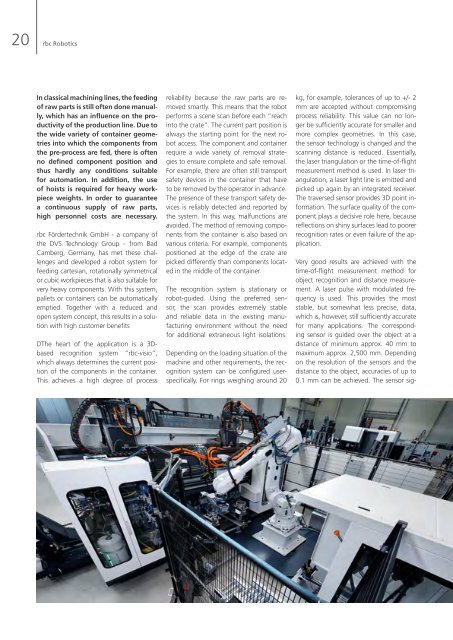
In classical machining lines, the feeding<br />
of raw parts is still often done manually,<br />
which has an influence on the productivity<br />
of the production line. Due to<br />
the wide variety of container geometries<br />
into which the components from<br />
the pre-process are fed, there is often<br />
no defined component position and<br />
thus hardly any conditions suitable<br />
for automation. In addition, the use<br />
of hoists is required for heavy workpiece<br />
weights. In order to guarantee<br />
a continuous supply of raw parts,<br />
high personnel costs are necessary.<br />
rbc Fördertechnik GmbH - a company of<br />
the DVS Technology Group - from Bad<br />
Camberg, Germany, has met these challenges<br />
and developed a robot system for<br />
feeding cartesian, rotationally symmetrical<br />
or cubic workpieces that is also suitable for<br />
very heavy components. With this system,<br />
pallets or containers can be automatically<br />
emptied. Together with a reduced and<br />
open system concept, this results in a solution<br />
with high customer benefits<br />
DThe heart of the application is a 3Dbased<br />
recognition system “rbc-visio”,<br />
which always determines the current position<br />
of the components in the container.<br />
This achieves a high degree of process<br />
reliability because the raw parts are removed<br />
smartly. This means that the robot<br />
performs a scene scan before each “reach<br />
into the crate”. The current part position is<br />
always the starting point for the next robot<br />
access. The component and container<br />
require a wide variety of removal strategies<br />
to ensure complete and safe removal.<br />
For example, there are often still transport<br />
safety devices in the container that have<br />
to be removed by the operator in advance.<br />
The presence of these transport safety devices<br />
is reliably detected and reported by<br />
the system. In this way, malfunctions are<br />
avoided. The method of removing components<br />
from the container is also based on<br />
various criteria. For example, components<br />
positioned at the edge of the crate are<br />
picked differently than components located<br />
in the middle of the container.<br />
The recognition system is stationary or<br />
robot-guided. Using the preferred sensor,<br />
the scan provides extremely stable<br />
and reliable data in the existing manufacturing<br />
environment without the need<br />
for additional extraneous light isolations.<br />
Depending on the loading situation of the<br />
machine and other requirements, the recognition<br />
system can be configured userspecifically.<br />
For rings weighing around 20<br />
kg, for example, tolerances of up to +/- 2<br />
mm are accepted without compromising<br />
process reliability. This value can no longer<br />
be sufficiently accurate for smaller and<br />
more complex geometries. In this case,<br />
the sensor technology is changed and the<br />
scanning distance is reduced. Essentially,<br />
the laser triangulation or the time-of-flight<br />
measurement method is used. In laser triangulation,<br />
a laser light line is emitted and<br />
picked up again by an integrated receiver.<br />
The traversed sensor provides 3D point information.<br />
The surface quality of the component<br />
plays a decisive role here, because<br />
reflections on shiny surfaces lead to poorer<br />
recognition rates or even failure of the application.<br />
Very good results are achieved with the<br />
time-of-flight measurement method for<br />
object recognition and distance measurement.<br />
A laser pulse with modulated frequency<br />
is used. This provides the most<br />
stable, but somewhat less precise, data,<br />
which is, however, still sufficiently accurate<br />
for many applications. The corresponding<br />
sensor is guided over the object at a<br />
distance of minimum approx. 40 mm to<br />
maximum approx. 2,500 mm. Depending<br />
on the resolution of the sensors and the<br />
distance to the object, accuracies of up to<br />
0.1 mm can be achieved. The sensor signals<br />
are recorded and combined with the<br />
corresponding direction of movement and<br />
speed. The result of the object scan is a<br />
point cloud. The acquisition of this point<br />
cloud is used for pre-processing in the application.<br />
The sensor used plays a decisive<br />
role here. Due to the continuous further<br />
development of sensors from various manufacturers,<br />
significant progress has been<br />
made in recent years in terms of both performance<br />
and size.<br />
With the system used by rbc, the evaluation<br />
of the data is component-specific. The<br />
evaluation of the scan data after detection<br />
(postprocessing) is carried out by means of<br />
PC-based software. This means that the<br />
point cloud is examined for lines or circles<br />
according to a defined algorithm and then<br />
evaluated, which provides very robust and<br />
reliable results. The overall geometry of<br />
the component plays only a limited role in<br />
this type of evaluation. For example, it is<br />
possible to scan partial characteristics and<br />
only evaluate them. The remaining component<br />
information is not relevant and is<br />
therefore neglected. The application then<br />
only uses the minimal scan data. This has<br />
enormous advantages with regard to rational<br />
data acquisition and processing<br />
with a significant time advantage.<br />
The evaluation times for the usual applications<br />
are approx. one second. A further<br />
advantage of the system is that several<br />
sensors can be evaluated with only one<br />
PC. For example, the component position<br />
in the container can be recorded first and<br />
then partially a geometry area for additional<br />
inspection of a feature. In addition,<br />
the 3D scanner including PC is optimally<br />
integrated into the overall control concept<br />
and offers extensive diagnostic options. A<br />
live image of the current scan, switchable<br />
languages of the operator dialogs and remote<br />
access are obligatory.<br />
system. If the gripping system is designed<br />
for different component geometries, the<br />
changeover to other components can be<br />
carried out without much effort at the<br />
push of a button. For rings, for example,<br />
this is very easy and optimal to implement,<br />
as these have a simple component geometry.<br />
After removing the workpiece from the<br />
pallet or from the container, the robot<br />
loads the first operation of the machining<br />
line and ensures a continuous flow of<br />
parts. The influence of the operators at this<br />
important interface of the system is thus<br />
minimized and limited to the logistics of<br />
container infeed and outfeed.<br />
rbc Fördertechnik is on its way to the<br />
future of “Industry 4.0” with the development<br />
of process-safe, robot-supported<br />
component feeding. As part of the<br />
DVS Technology Group, with the synergies<br />
from design and production, rbc<br />
gives its customers impulses for more<br />
competitiveness and flexibility in industrial<br />
production.<br />
•<br />
Author:<br />
Dirk Hablick<br />
rbc Robotics<br />
The robot system integrated by rbc is usually<br />
equipped with a pneumatic gripper<br />
and is therefore capable of scanning and<br />
emptying several provided pallets. The<br />
components are roughly pre-oriented on<br />
the pallets and in different levels, with or<br />
without intermediate layers. The reliable<br />
detection in the scenario of the component<br />
stack (Z-layer) distinguishes the rbc