Aufbauanleitung TransFlex - SINOtec GmbH
Aufbauanleitung TransFlex - SINOtec GmbH
Aufbauanleitung TransFlex - SINOtec GmbH
Erfolgreiche ePaper selbst erstellen
Machen Sie aus Ihren PDF Publikationen ein blätterbares Flipbook mit unserer einzigartigen Google optimierten e-Paper Software.
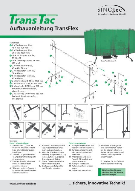
<strong>Aufbauanleitung</strong> <strong>TransFlex</strong><br />
Stückliste<br />
1 2 x Vierkantrohr blau,<br />
45 x 45 x 720 mm<br />
2 2 x Vierkantrohr blau,<br />
30 x 60 x 1830 mm<br />
3 10 x Sechskantschraube,<br />
M 16 x 40<br />
4 10 x Unterlegscheibe, 16 mm<br />
(38 mm)<br />
5 2 x Vierkantrohr blau,<br />
45 x 45 x 94 mm<br />
6 2 x Endstopfen schwarz,<br />
30 x 60 mm<br />
7 6 x Endstopfen schwarz,<br />
45 x 45 mm<br />
8 2 x Rohr silber, Ø 33,5 x 2100 mm<br />
9 2 x Rohr blau, Ø 33,5 x 100 mm<br />
10 2 x Laufrolle, Ø 100 mm, 130 mm<br />
hoch mit Gewindezapfen,<br />
ohne Bremse<br />
11 2 x Laufrolle, Ø 100 mm, 130 mm<br />
hoch mit Gewindezapfen,<br />
mit Bremse<br />
1. 2. 4. 5. 6. 7.<br />
8.<br />
(1)<br />
(2)<br />
Montage<br />
Form 1 ohne Ausleger:<br />
1. Vierkantrohr (1) blau als<br />
Fußprofil mit Vierkantrohr<br />
blau (2) als Ständer zusammenfügen.<br />
2. 2 Rollen (1x gebremst und<br />
1x ungebremst) in Fußprofil<br />
einschrauben.<br />
3. Zweiten Ständer wie unter<br />
Punkt 1-2 beschrieben<br />
zusammenfügen.<br />
4. Silbernes, unteres Querrohr<br />
in ersten Ständer einstecken<br />
und verschrauben.<br />
www.sinotec-gmbh.de<br />
7<br />
9. 10.<br />
1<br />
10<br />
2<br />
5. Silbernes, unteres Querrohr<br />
in zweiten Ständer einste -<br />
cken und verschrauben.<br />
6. Wird die Wand mit einem<br />
Vorhang ausgerüstet 11 (13)<br />
Haken auf obere, silberne<br />
Querstange ein fädeln.<br />
7. Obere Querstange einführen<br />
und verschrauben.<br />
8. Endkappen in Fußprofile<br />
und Ständer einsetzen.<br />
3<br />
4<br />
11<br />
12. 12a.<br />
8<br />
Form 2 mit Ausleger:<br />
9. Ausleger-Vierkantrohr einstecken<br />
und verschrauben.<br />
10. Rundes Ausleger-Gelenkrohr<br />
einstecken und verschrauben.<br />
11. Andere Seite wie unter<br />
Punkt 9 -10 beschrieben<br />
zusammenbauen.<br />
12. Ausleger aufstecken.<br />
13. Auf anderer Seite wieder -<br />
holen.<br />
14. Endkappen einstecken.<br />
4<br />
3<br />
<strong>TransFlex</strong> Stellwand<br />
Bitte beachten Sie auch<br />
die Infos über die TransTac<br />
Schutzvorhänge!<br />
… sichere, innovative Technik!<br />
3<br />
4<br />
14.<br />
2<br />
15. Entweder Vorhänge mit<br />
den vorhandenen Haken<br />
an die oberen, silbernen<br />
Rohre hängen, oder Lamellen<br />
mit Schwing schellen<br />
anschrauben.<br />
2 Lamellen für die Gelenke<br />
haben Sonderlackierung.<br />
6<br />
9<br />
5<br />
7
Assembly Instruction <strong>TransFlex</strong><br />
List of parts<br />
1 2 x rectangular hollow section,<br />
blue, 45 x 45 x 720 mm<br />
2 2 x rectangular hollow section,<br />
blue, 30 x 60 x 1830 mm<br />
3 10 x hexagon screw, M 16 x 40<br />
2<br />
4 10 x washer, 16 mm (38 mm)<br />
5 2 x rectangular hollow sections,<br />
blue, 45 x 45 x 94 (adapter)<br />
<strong>TransFlex</strong> Screen<br />
6 2 x end cap, black, 30 x 60 mm<br />
7 6 x end cap, black, 45 x 45 mm<br />
8<br />
9<br />
2 x pipe, silver, Ø 33,5 x 2100 mm<br />
2 x pipe, blue, Ø 33,5 x 100 mm<br />
1<br />
6<br />
10 2 x castors, Ø 100 mm, 130 mm<br />
high, with threaded rod,<br />
without brake<br />
11 2 x castors, Ø 100 mm, 130 mm<br />
high, with threaded rod,<br />
with brake<br />
7<br />
10<br />
3<br />
11<br />
4<br />
8<br />
4<br />
3<br />
3<br />
4<br />
9<br />
5<br />
2<br />
1. 2. 4. 5. 6. 7.<br />
8.<br />
(1)<br />
(2)<br />
Montage<br />
Option 1 without arms:<br />
1. Insert rectangular hollow<br />
section (2) blue into the<br />
rectangular hollow section<br />
(1) used as feet.<br />
2. Bolt 2 castors (1 x with<br />
brake, 1 x without brake)<br />
to the feet.<br />
3. Repeat steps 1-2 above for<br />
the other stand.<br />
4. Insert the lower cross bar<br />
(silver) into one stand and<br />
bolt it.<br />
www.sinotec-gmbh.de<br />
9. 10.<br />
5. Insert the lower cross bar<br />
(silver) into the second<br />
stand and bolt it.<br />
6. If the partition is equipped<br />
with curtains, then insert<br />
the hooks 11pcs. (13 pcs.)<br />
onto the upper cross bar.<br />
7. Bolt the upper cross-bar<br />
to each of the stands.<br />
8. Put the end caps into the<br />
stands and feet.<br />
12. 12a.<br />
Option 2 with arms:<br />
9. Insert the adapter into the<br />
stand and bolt into place<br />
10. Put the small pipe (9)<br />
into the adapter and bolt<br />
into place<br />
11. Repeat steps 9 - 10 for the<br />
other stand<br />
12. Fit the arm into the adapter<br />
13. Repeat step 12 for the<br />
other stand<br />
14. Put the end caps into<br />
the arms<br />
15. If the partition is equipped<br />
with curtains put the hooks<br />
Please pay attention to the<br />
information about the Trans-<br />
Tac protection curtains!<br />
… sichere, innovative Technik!<br />
14.<br />
into the arms and complete<br />
it by hanging the curtains<br />
into the hooks.<br />
If the partition is equipped<br />
with strips bolt the strips<br />
to the cross-bar using the<br />
swing clamps. 2 strips have<br />
a special punching. They<br />
must be hung at each<br />
stand/adapter.<br />
7


