25. Internationale Holzbau-Forum (IHF 2019) - Band III

Sie wollen auch ein ePaper? Erhöhen Sie die Reichweite Ihrer Titel.
YUMPU macht aus Druck-PDFs automatisch weboptimierte ePaper, die Google liebt.
8<br />
<strong>25.</strong> <strong>Internationale</strong>s <strong>Holzbau</strong>-<strong>Forum</strong> <strong>IHF</strong> <strong>2019</strong><br />
Experimental full-scale testing of a multistory timber frame building concerning dynamic properties | U. Oberbach<br />
2.2. Foundation<br />
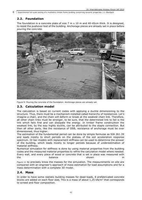
The foundation is a concrete plate of size 7 m x 10 m and 40-45cm thick. It is designed,<br />
to resist the pushover test of the building. Anchorage pieces are already set in place before<br />
pouring the concrete.<br />
Figure 9: Pouring the concrete of the foundation. Anchorage pieces are already set.<br />
2.3. Calculation model<br />
The calculation is based on current codes with applying a ductile dimensioning to the<br />
structure. Thus, there must be a mechanism installed called hierarchy of resistances. Let’s<br />
imagine a chain, and the chain will deform or break at the weakest chain link. Therefore,<br />
all other chain links must be stronger, to be sure, that the determined link to fail is the<br />
link which fails first and can dissipate the energy. In timber frame construction the<br />
weakest link, by the way highly ductile, can be attributed to the staple connection. But<br />
then all other parts, like the resistance of OSB, resistance of anchorage must be over<br />
dimensioned, thus higher.<br />
The estimation of the fundamental period can be done by simple formulas as SIA 261.39<br />
and leads mostly to short periods on the plateau of the soil acceleration response<br />
spectrum. Or bar models with replacement stiffness can be used to determine the answer<br />
of the building, which leads mostly to longer periods because of underestimation of<br />
material stiffness.<br />
Numerical simulation for stiffness is done by using material properties from the building<br />
codes and the measured material properties to refine the calculation model where needed.<br />
Every wall, and every piece of wood or concrete that is set in place was measured with<br />
the balance shown in<br />
Figure 11 to precisely know the masses for the simulation. The measurements on site are<br />
compared with an engineer’s approach of mass estimation for load assumptions and for a<br />
mass determination with a complete 3D model.<br />
2.4. Mass<br />
In order to have some realistic building masses for dead-loads, 8 prefabricated concrete<br />
blocks are added on each floor slab. This is a mass of about 1,25 kN/m 2 that corresponds<br />
to screed and floor composition.<br />
42