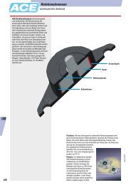
LOCKED-Series PL/SL and P LOCKED-Serie PL/SL und P LOCKED ...
LOCKED-Series PL/SL and P LOCKED-Serie PL/SL und P LOCKED ...
LOCKED-Series PL/SL and P LOCKED-Serie PL/SL und P LOCKED ...

Sie wollen auch ein ePaper? Erhöhen Sie die Reichweite Ihrer Titel.
YUMPU macht aus Druck-PDFs automatisch weboptimierte ePaper, die Google liebt.
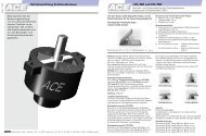
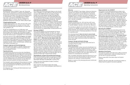
<strong>LOCKED</strong>-<strong>Serie</strong> P<br />
Betriebsanleitung<br />
Gewährleistung<br />
Bauartbedingt ist bei <strong>LOCKED</strong>-P Typen der Toleranzbereich<br />
(Toleranz, Zylinderform) zwischen Achse/Welle <strong>und</strong><br />
Klemmung innerhalb des durch die Anwendung definierten<br />
Bereichs einzuhalten. Eine Abweichung hiervon kann<br />
im Dauerbetrieb zu einer Schädigung der <strong>LOCKED</strong>-P<br />
Type oder zu geringeren Haltekräften führen. Es ist<br />
besonders darauf zu achten, dass der <strong>LOCKED</strong>-P im<br />
geöffneten Zust<strong>and</strong> die Achse bzw. Welle völlig frei gibt.<br />
Umgebungsbedingungen<br />
Umgebungstemperatur min. 10°C <strong>und</strong> max. 45°C, pneumatischer<br />
Betriebsdruck min. 5,5 bar <strong>und</strong> max. 6 bar<br />
(4 bar bei Spezialausführung), Betrieb nur mit getrockneter<br />
gefilterter Luft.<br />
Es gilt eine Gewährleistung von 24 Monaten nach<br />
Lieferung, höchstens aber eine Zyklusanzahl von 1 000 000<br />
Klemmungen (keine Notfall- oder Bremsklemmungen).<br />
Der K<strong>und</strong>e muss im Gewährleistungsfall die tatsächliche<br />
Anzahl der Klemmungen in geeigneter Form nachweisen.<br />
Das Klemmelement dient nicht zum Sichern von Lasten.<br />
Die bestimmungsgemäße Verwendung der Klemmelemente<br />
setzt voraus, dass diese nur im Rahmen der durch<br />
die technische Spezifikation angegebenen Möglichkeiten<br />
eingesetzt werden. Andere Verwendungen schließen jegliche<br />
weitere Leistungen aus.<br />
Transport, Lagerung <strong>und</strong> Zwischenlagerung<br />
Die Klemmelemente sollten im geölten Zust<strong>and</strong> <strong>und</strong> in<br />
der von ACE ausgewählten Verpackung gelagert bzw.<br />
zwischengelagert werden.<br />
Typenbezeichnung<br />
Die eingravierte <strong>Serie</strong>nnummer dient der Identifikation<br />
<strong>und</strong> Rückverfolgbarkeit des jeweiligen Klemmelementes.<br />
Alle Gewährleistungsansprüche erlöschen durch das Entfernen<br />
oder Unkenntlichmachen der Typenbezeichnung<br />
<strong>und</strong> der <strong>Serie</strong>nnummer. Die Typenbezeichnung befindet<br />
sich bei <strong>LOCKED</strong>-P Klemmelementen auf der Zwischenplatte<br />
unter den Druckluft <strong>und</strong> Sensoranschlüssen.<br />
Nur komplett zusammengebaute Klemmelemente werden<br />
durch die Gewährleistung abgedeckt. Eine Demontage<br />
bzw. Ausein<strong>and</strong>erbauen der Klemmung durch den K<strong>und</strong>en<br />
wird untersagt.<br />
Eine Reparatur bzw. Prüfung der Klemmelemente muss<br />
durch ACE erfolgen.<br />
Besonderheiten <strong>LOCKED</strong>-P<br />
Die Funktion der Klemmelemente hängt von der Kombination<br />
<strong>LOCKED</strong>-P zur Klemmfläche ab. Bei Verwendung<br />
an einem ISO VDMA Zylinder sind daher die Eigenschaften<br />
der Kolbenstange wichtige Einflussgrößen.<br />
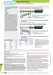
Die Klemmelemente sind in ihrer St<strong>and</strong>artausführung<br />
für die folgenden Bedingungen optimiert: Durchmesser<br />
„Stangendurchmesser mit Toleranzfeld h9“, Werkstoff<br />
Kolbenstange (herstellerabhängig) z.B. CF63 oder<br />
16MnCr5. Im Idealfall sollte die Stange oberflächengehärtet<br />
sein, um die Lebensdauer zu erhöhen. Die optionalen<br />
Endlagenschalter sind nicht geeignet um die Funktion zu<br />
überprüfen <strong>und</strong> dienen ausschließlich zur Kontrolle des<br />
Schaltzust<strong>and</strong>es. Im Falle eines Defektes kann das<br />
Klemmelement trotz gegenteiliger Anzeige geöffnet sein.<br />
Montage <strong>LOCKED</strong>-P<br />
Rote Verschlusskappe <strong>und</strong> Verschlussteile für Sensoranschlüsse<br />
bei Bedarf entfernen. An dem mit „open“<br />
bezeichneten Anschluss entsprechende Pneumatikverbindung<br />
anbringen. Das Klemmelement muss zur Montage,<br />
je nach Ausführung, mit 4 bar bzw. 6 bar beaufschlagt<br />
werden (Bild 1). Ohne Druck ist das System nicht montierbar.<br />
Nun kann das Klemmelement über die Stange<br />
geführt werden. Das Element in seiner vorgesehenen<br />
Position ausrichten <strong>und</strong> mit reduziertem Anzugsmoment<br />
anschrauben (Bild 2). Den Luftdruck auf 0 Bar reduzieren<br />
bis die <strong>LOCKED</strong>-P Type sich auf der Achse bzw. Welle<br />
zentriert, Schrauben eventuell wieder etwas lösen, um<br />
das Ausrichten zu ermöglichen. Nachdem das Klemmelement<br />
in seiner vorgesehenen Position zentriert ist, die<br />
Befestigungsschrauben mit definiertem Anzugsmoment<br />
(Tabelle 1) anziehen. Optional können zur Kontrolle des<br />
Schaltzust<strong>and</strong>es Endschalter mit Gewinde M8 in die vorgesehenen<br />
Bohrungen eingeschraubt werden.<br />
Abschließende zwingend durchzuführende Prüfungen<br />
Prüfen Sie das System zunächst mit geringeren Kräften.<br />
Evtl. Vorkehrungen treffen für den Fall, dass aufgr<strong>und</strong><br />
fehlerhafter Montage die Haltekräfte zu gering sind.<br />
Sollten Sie keine einw<strong>and</strong>freie Funktion erreichen,<br />
kontaktieren Sie ACE.<br />
Nach Anschluss des Systems fahren Sie einige<br />
Probezyklen, um die Funktionsfähigkeit abschließend zu<br />
prüfen.<br />
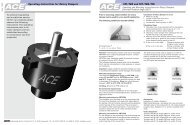
<strong>LOCKED</strong>-<strong><strong>Serie</strong>s</strong> P<br />
Operating Instructions<br />
Warranty<br />
Due to the <strong>LOCKED</strong>-P Type design, tolerances (tolerance,<br />
cylinder form) between the axis/spindle <strong>and</strong> clamping<br />
within the application must be adhered to. Deviations<br />
during continuous operation can lead to damages of the<br />
<strong>LOCKED</strong>-P Type or to lower holding forces. It must be<br />
made sure that when opened, the <strong>LOCKED</strong>-P releases the<br />
axis or spindle completely.<br />
Ambient Condition<br />
Ambient temperature min. 10°C <strong>and</strong> max. 45°C, pneumatic<br />
operating pressure min. 5,5 bar max. 6 bar (4 bar<br />
for special designs), operation only with dry, filtered air.<br />
The warranty is valid for 24 months after delivery, with a<br />
maximum of 1 000 000 clamping cycles (no emergency or<br />
brake clamping). The customer must show suitable proof<br />
for the actual number of clamping operations in the case<br />
of a warranty claim.<br />
The clamping element does not serve to secure loads.<br />
The application of these clamping elements assumes that<br />
they are only used according to their stated specifications.<br />
Other usage is strictly prohibited <strong>and</strong> debars any<br />
further services.<br />
Transport, Storage <strong>and</strong> Interim Storage<br />
The clamping elements should be stored oiled <strong>and</strong> in<br />
packaging chosen by ACE.<br />
Model Identification<br />
The engraved serial number serves the identification traceability<br />
of the individual clamping elements. All warranty<br />
claims expire when these IDs are removed or made<br />
illegible. The model identification for the <strong>LOCKED</strong>-P clamping<br />
element is located on the inner plate <strong>und</strong>er the connections<br />
for compressed air <strong>and</strong> sensors.<br />
Only completely assembled clamping elements are covered<br />
by the warranty. Disassembling or dismounting the<br />
clamps by the customer is strictly prohibited.<br />
Repairs or service of the clamping elements must be performed<br />
by ACE.<br />
Requirements for the <strong>LOCKED</strong>-P<br />
The function of the clamping elements relates to the<br />
<strong>LOCKED</strong>-P combination with the clamping area. When<br />
using on an ISO VDMA cylinder, the characteristics of the<br />
piston rod are therefore important factors. The clamping<br />
elements are optimized in their st<strong>and</strong>ard design for the<br />
following requirements: Diameter ”rod diameter with<br />
tolerance zone h9“, material piston rod (depending on<br />
manufacturer) for example, CF63 or 16MnCr5. Ideally the<br />
rod should be surface-hardened to increase its lifetime.<br />
The optional limit switches are not suited to check the<br />
function <strong>and</strong> serve exclusively to check the condition of<br />
the switch status. In case of a defect, the clamping element<br />
can be released despite a contrary signal.<br />
Mounting the <strong>LOCKED</strong>-P<br />
Remove the red locking cap <strong>and</strong> locking parts for the<br />
sensor connections if required. Mount the appropriate<br />
pneumatic connection to the link labeled “open”. The<br />
clamping element must be filled with 4 bar or 6 bar<br />
depending on the model (picture 1). The system cannot<br />
be mounted without pressure. The clamping element<br />
can now be guided over the rod. Align the element in its<br />
designated position <strong>and</strong> screw on using a reduced tightening<br />
torque (picture 2). Reduce the air pressure to 0 bar<br />
until the <strong>LOCKED</strong>-P type centers on the axis, i.e. spindle;<br />
the screws may require loosening to enable exact<br />
alignment. After the clamping element is centered in its<br />
required position, the fastening screws are to be tightened<br />
with the necessary tightening torque (table 1). Optional<br />
end switches thread size M8 can be screwed into the<br />
intended bores to check the switch condition.<br />
M<strong>and</strong>atory Final Checks<br />
First check the system with light forces; safety procedures<br />
should be implemented in case the holding forces are<br />
too low due to incorrect mounting.<br />
Please contact ACE if the device does not function<br />
correctly.<br />
Operate a few test cycles after mounting the system to<br />
finally check the system’s functional capability.