LOCKED-Series PL/SL and P LOCKED-Serie PL/SL und P LOCKED ...
LOCKED-Series PL/SL and P LOCKED-Serie PL/SL und P LOCKED ...
LOCKED-Series PL/SL and P LOCKED-Serie PL/SL und P LOCKED ...

Sie wollen auch ein ePaper? Erhöhen Sie die Reichweite Ihrer Titel.
YUMPU macht aus Druck-PDFs automatisch weboptimierte ePaper, die Google liebt.
St<strong>and</strong> 7.2008<br />
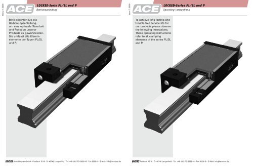
Bitte beachten Sie die<br />
Bedienungsanleitung,<br />
um eine optimale St<strong>and</strong>zeit<br />
<strong>und</strong> Funktion unserer<br />
Produkte zu gewährleisten.<br />
Sie umfasst alle Klemmelemente<br />
der Typen <strong>PL</strong>/<strong>SL</strong><br />
<strong>und</strong> P.<br />
<strong>LOCKED</strong>-<strong>Serie</strong> <strong>PL</strong>/<strong>SL</strong> <strong>und</strong> P<br />
Betriebsanleitung<br />
Stoßdämpfer GmbH · Postfach 15 10 · D- 40740 Langenfeld · Tel. +49-(0)2173-9226-10 · Fax 9226-19 · E-Mail: info@ace-ace.de<br />
Issue 7.2008<br />
To achieve long lasting <strong>and</strong><br />
trouble-free service life for<br />
our products please observe<br />
the following instructions.<br />
These operating instructions<br />
refer to all clamping<br />
elements of the series <strong>PL</strong>/<strong>SL</strong><br />
<strong>and</strong> P.<br />
<strong>LOCKED</strong>-<strong><strong>Serie</strong>s</strong> <strong>PL</strong>/<strong>SL</strong> <strong>and</strong> P<br />
Operating Instructions<br />
Postfach 15 10 · D- 40740 Langenfeld · Tel. +49-(0)2173-9226-10 · Fax 9226-19 · E-Mail: info@ace-ace.de
Wichtige Hinweise<br />
Diese Betriebsanleitung dient zur störungsfreien<br />
Nutzung der ACE <strong>LOCKED</strong> Klemmelemente <strong>und</strong> ist<br />
Vorraussetzung für die Erfüllung eventueller<br />
Gewährleistungsansprüche.<br />
Bitte lesen Sie deshalb vor Gebrauch der Klemmelemente<br />
unbedingt diese Betriebsanleitung.<br />
Die im Katalog angegebenen Grenzwerte, z. B. für Drücke,<br />
Kräfte, Momente <strong>und</strong> Temperaturen, sind einzuhalten.<br />
Sorgen Sie für ordnungsgemäß aufbereitete Druckluft.<br />
Behalten Sie die einmal gewählte Zusammensetzung<br />
des Mediums über die gesamte Betriebsdauer bei.<br />
Berücksichtigen Sie die vorherrschenden Umweltbedingungen.<br />
Einbau <strong>und</strong> Inbetriebnahme darf nur durch qualifiziertes<br />
Fachpersonal gemäß der vorliegenden Betriebs- <strong>und</strong><br />
Einbauanleitung erfolgen.<br />
Sicherheitshinweise<br />
Je nach Verwendungszweck der Klemmelemente kann<br />
Gefahr entstehen durch:<br />
● Quetschung bei Montage durch ungesicherte<br />
Anschlusskonstruktionen<br />
● Verletzungen durch nicht sachgemäße<br />
Pneumatikverbindungen<br />
● Störungen der Pneumatikversorgung, z.B. durch<br />
Druckschwankungen<br />
● lose Befestigungsschrauben, siehe empfohlene<br />
Anzugsmomente Tabelle 1<br />
Die angegebenen minimalen Reaktionszeiten werden in<br />
Abhängigkeit vom Systemaufbau erreicht. Dafür sind<br />
Leitungslängen, Ventile, Querschnitte <strong>und</strong> Steuerung<br />
entsprechend zu optimieren.<br />
Die Haltekräfte werden abhängig von Schienentyp,<br />
Schienengröße, Schienenoberfläche (gefettet, geölt,<br />
trocken) <strong>und</strong> Einsatzdauer erreicht. Entsprechende<br />
Lasten werden analog dazu gehalten bzw. geklemmt<br />
unter der Vorraussetzung, dass alle Systemparameter<br />
entsprechend ausgelegt sind.<br />
Die jeweils angegebenen Haltekräfte wurden auf<br />
trockener Schiene für Rollenschienenführungen (INA,<br />
Rexroth/STAR) ermittelt, bei <strong>and</strong>eren Profilen sind<br />
abweichende Haltekräfte möglich. Kalkulieren Sie bei<br />
gefetteten Schienen, abhängig vom verwendeten Fett<br />
<strong>und</strong> Belag, bei Sintermetallausführung mit 60% <strong>und</strong><br />
bei Stahlbelagausführungen mit 90% der im Katalog<br />
angegebenen Haltekräfte.<br />
<strong>LOCKED</strong>-<strong>Serie</strong> <strong>PL</strong>/<strong>PL</strong>K <strong>und</strong> <strong>SL</strong>/<strong>SL</strong>K<br />
Betriebsanleitung<br />
Bedienteile <strong>und</strong> Anschlüsse<br />
Befestigungsvorrichtung je nach Ausführung:<br />
Zwei Befestigungslöcher mit metrischen St<strong>and</strong>ardgewinden<br />
sind je nach Baugröße im Halteklotz der<br />
<strong>LOCKED</strong> Typen vorh<strong>and</strong>en.<br />
Ab Nenngröße 45 mm empfehlen wir die Verwendung<br />
eines zweiten gegenüberliegenden Halteklotzes mit<br />
zwei zusätzlichen Gewindebohrungen. Empfohlene<br />
Schrauben <strong>und</strong> entsprechende Anzugsmomente für die<br />
jeweiligen Typen entnehmen Sie der Tabelle 1.<br />
Zwei Druckluftanschlüsse befinden sich unten seitlich<br />
im Halteklotz. Anschlüsse je nach Baugröße (Tabelle 1).<br />
Normalbetrieb: Anschluss einseitig, zur schnelleren<br />
Entlüftung auch beidseitig verwendbar.<br />
Wichtig: Auf ausreichende Entlüftung achten. Funktion<br />
nach Installation sorgfältig überprüfen.<br />
Important Notes<br />
This operating manual serves to ensure the troublefree<br />
use of the ACE <strong>LOCKED</strong> clamping elements <strong>and</strong> is<br />
a prerequisite for the compliance to possible warranty<br />
claims.<br />
Please read this operating manual prior to using the<br />
clamping elements.<br />
The limit values, i.e. for pressures, forces, torques <strong>and</strong><br />
temperatures, quoted in this catalogue are to be adhered<br />
to.<br />
Provide for properly prepared compressed air. Keep the<br />
initially chosen composition of the medium for the total<br />
duration of operation. Consider the prevailing environmental<br />
conditions.<br />
Installation <strong>and</strong> initial operation may only be made by<br />
qualified personnel <strong>and</strong> according to available operating<br />
<strong>and</strong> mounting manuals.<br />
Safety Advice<br />
Danger can arise depending on the following factors:<br />
● Unsecured connecting structures can lead to damage<br />
when mounting.<br />
● Incorrect pneumatic connections can lead to injuries.<br />
● Failures of the pneumatic supply can occur, for<br />
example, due to pressure fluctuations.<br />
● Loose mounting screws; for recommended tightening<br />
torques see table 1.<br />
The stated minimum response times are reached<br />
depending on the system structure. Line lengths, valves,<br />
cross sections, <strong>and</strong> controls are to be optimized<br />
accordingly.<br />
The holding forces are reached depending on the rail<br />
type, rail size, rail surface (greased, oiled, dry) <strong>and</strong><br />
length of operation. The corresponding loads are held<br />
or clamped dependant on the total effect of the system<br />
parameters <strong>and</strong> should be designed accordingly.<br />
The individually stated holding forces were determined<br />
on a dry rail for roller rail systems (INA, Rexroth/STAR);<br />
differing holding forces are possible for other profiles.<br />
For sintered metal designs calculate as for greased<br />
rails. With greased rails or coated rails calculate with<br />
60% holding, depending on the grease used <strong>and</strong> for<br />
steel coating with 90% of the holding forces given in<br />
the catalogue.<br />
<strong>LOCKED</strong>-<strong><strong>Serie</strong>s</strong> <strong>PL</strong>/<strong>PL</strong>K <strong>and</strong> <strong>SL</strong>/<strong>SL</strong>K<br />
Operating Instructions<br />
Control Elements <strong>and</strong> Connections<br />
Mounting the device depends on design:<br />
Two fastening holes with metric st<strong>and</strong>ard threads<br />
dependent on size are located in the holding block of<br />
the <strong>LOCKED</strong> types.<br />
Starting at nominal size 45 mm, we recommend the<br />
use of a second opposing holding block with two additional<br />
threaded holes. Recommended screws <strong>and</strong> the<br />
corresponding tightening torques for the individual<br />
types can be taken from table 1.<br />
Two compressed air connections are located on the<br />
lower side of the holding block. Connections depend<br />
on the size (table 1). Normal Operation: Single connection,<br />
for quick venting both connections can be used.<br />
Important: Ensure sufficient ventilation. Check for<br />
correct functionality after mounting.
<strong>LOCKED</strong>-<strong>Serie</strong> <strong>PL</strong>/<strong>PL</strong>K <strong>und</strong> <strong>SL</strong>/<strong>SL</strong>K<br />
Betriebsanleitung<br />
Gewährleistung<br />
Umgebungsbedingungen<br />
Umgebungstemperatur 10°C bis 45°C; pneumatischer<br />
Betriebsdruck min. 5,5 bar <strong>und</strong> max. 6 bar (4 bar Spezialausführung).<br />
Entsprechende Kennzeichnung auf dem<br />
Klemmelement beachten! Betrieb nur mit getrockneter<br />
gefilterter Luft.<br />
Für die Sicherheitsklemmsysteme gilt eine Gewährleistung<br />
von 24 Monaten nach Auslieferung, längstens<br />
aber eine Klemmzyklusanzahl von maximal 1 000 000<br />
Klemmungen bzw. 500 Notfallbremsungen. Der K<strong>und</strong>e<br />
muss im Gewährleistungsfall die tatsächliche Anzahl<br />
der Klemmungen in geeigneter Form nachweisen.<br />
Wichtig! Die Klemmelemente dienen nicht zum Sichern<br />
von schwebenden Lasten!<br />
Transport, Lagerung <strong>und</strong> Zwischenlagerung<br />
Die Klemmelemente sollten im geölten Zust<strong>and</strong> <strong>und</strong> in<br />
der von ACE ausgewählten Verpackung gelagert bzw.<br />
zwischengelagert werden.<br />
Typenbezeichnung<br />
Die eingravierte <strong>Serie</strong>nnummer dient der Identifikation<br />
<strong>und</strong> Rückverfolgbarkeit des jeweiligen Klemmelementes.<br />
Alle Gewährleistungsansprüche erlöschen durch<br />
das Entfernen oder Unkenntlichmachen der Typenbezeichnung<br />
<strong>und</strong> der <strong>Serie</strong>nnummer. Die Typenbezeichnung<br />
befindet sich bei <strong>LOCKED</strong> Klemmelementen auf<br />
der äußeren Seite des Haltekörpers.<br />
Nur komplett zusammengebaute Klemmelemente werden<br />
durch die Gewährleistung abgedeckt. Eine Demontage<br />
bzw. ein Ausein<strong>and</strong>erbauen der Klemmung durch<br />
den K<strong>und</strong>en wird untersagt.<br />
Eine Reparatur bzw. Prüfung der Klemmelemente muss<br />
durch ACE erfolgen.<br />
Inbetriebnahme<br />
Achten Sie auf einen verzugfreien Einbau <strong>und</strong> auf die<br />
Einhaltung der maximalen Klemmleistung laut Katalogangabe.<br />
Einbau <strong>und</strong> Montage siehe letzte Seite.<br />
Prüfen Sie, ob die eingravierte Typenbezeichnung des<br />
einzubauenden Klemmelementes mit dem gewünschten<br />
Klemmelement übereinstimmt.<br />
Das Pneumatikventil (5/3 bzw. 3/2 Wegeventil, Nenngröße<br />
siehe Tabelle 1) in der Nähe des Klemmelementes<br />
montieren <strong>und</strong> mit Ø 6 bzw. Ø 8 mm Schlauch verbinden.<br />
Je länger der Leitungsweg, desto länger die<br />
Reaktionszeiten.<br />
Empfehlung für kurze Reaktionszeiten: Je Bremse<br />
ein Schnellschaltventil mit zwei Schnellentlüftern verwenden.<br />
Nach sachgemäßer Installation des Klemmelementes<br />
ist die Betriebssicherheit zu prüfen:<br />
● Die Beweglichkeit ist durch manuelles Verschieben<br />
der Lineareinheit zu prüfen.<br />
● Der Klemmvorgang ist durch Verschieben der<br />
Lineareinheit zu prüfen.<br />
● Beim mit Druck beaufschlagten Element sind alle<br />
Pneumatikverbindungen auf Dichtheit zu prüfen.<br />
● Alle Befestigungsschrauben sind auf ihr vorgeschriebenes<br />
Anzugsmoment zu prüfen.<br />
Eine Nachjustierung ist aufgr<strong>und</strong> der werkseitig eingestellten<br />
Passungspaarung nach sachgerechter Montage<br />
nicht erforderlich.<br />
Starten Sie einen Probelauf.<br />
Type Gewinde Anzugs- Druckluft-<br />
Halteklotz moment anschluss<br />
<strong>PL</strong>K/<strong>SL</strong>K 15 M5 10,7 M5<br />
<strong>PL</strong>/<strong>SL</strong> 20 M5 10,7 M5<br />
<strong>PL</strong>/<strong>SL</strong> 25;<br />
<strong>PL</strong>K/<strong>SL</strong>K 20, 25<br />
M6 18,3 M5<br />
<strong>PL</strong>/<strong>SL</strong> 30 M8 44,1 M5<br />
<strong>PL</strong>K/<strong>SL</strong>K 30 M8 44,1 G 1/8<br />
<strong>PL</strong>/<strong>SL</strong> 35, 45, 55;<br />
<strong>PL</strong>K/<strong>SL</strong>K 35, 45, 55<br />
M10 86,9 G 1/8<br />
<strong>PL</strong>/<strong>SL</strong> 65 M12 151 G 1/8<br />
Tabelle 1 Anziehmomente für Schrauben<br />
Warranty<br />
Ambient Condition<br />
Ambient temperature 10°C to 45°C; pneumatic operating<br />
pressure min. 5.5 bar <strong>and</strong> max. 6 bar (4 bar for<br />
special designs). Pay attention to the corresponding<br />
identification on the clamping element! Operation only<br />
with dry, filtered air.<br />
The warranty is valid for 24 months after delivery, with<br />
a maximum number of clamping cycles of 1 000 000<br />
clamping actions or 500 emergency braking actions.<br />
The customer must show suitable proof for the actual<br />
number of clamping cycles in case of a warranty claim.<br />
Important! The clamping element may not be used to<br />
secure floating loads!<br />
Transport, Storage <strong>and</strong> Interim Storage<br />
The clamping elements should be stored oiled <strong>and</strong> in<br />
packaging chosen by ACE.<br />
Model Identification<br />
The engraved serial number serves the identification<br />
traceability of the individual clamping elements. All<br />
warranty claims expire when these IDs are removed or<br />
made illegible. The model identification for the<br />
<strong>LOCKED</strong> clamping element is located on the outside<br />
of the body.<br />
Only completely assembled clamping elements are<br />
covered by the warranty. Disassembling or dismounting<br />
the clamping by the customer is strictly prohibited.<br />
Repairs or service of the clamping elements must be<br />
performed by ACE.<br />
<strong>LOCKED</strong>-<strong><strong>Serie</strong>s</strong> <strong>PL</strong>/<strong>PL</strong>K <strong>and</strong> <strong>SL</strong>/<strong>SL</strong>K<br />
Operating Instructions<br />
Start-Up<br />
To ensure a quick set-up <strong>and</strong> adherence to the maximum<br />
clamping capacity according to the catalogue.<br />
See installation <strong>and</strong> mounting instructions on the last<br />
page.<br />
Check if the engraved identification of the clamping<br />
element corresponds to the desired clamping element.<br />
Mount the pneumatic valve (5/3 or 3/2 directional control<br />
valve, nominal size see table 1) near the clamping<br />
element <strong>and</strong> connect to Ø 6 or Ø 8 mm hose. The longer<br />
the path of the hose, the longer the response times.<br />
Recommendation for short response times: Use a quick<br />
air-vent valve with two quick air bleeds per brake.<br />
After having installed the clamping element properly,<br />
the system’s operational safety should be checked:<br />
● Check the movability by manually traversing the<br />
linear unit.<br />
● The clamping process must be checked by traversing<br />
the linear unit.<br />
● When the element is filled with compressed air, all<br />
pneumatic connections must be checked for impermeability.<br />
● All fastening screws must be checked for their<br />
required tightening torque.<br />
Readjustment following correct installation is not<br />
required due to factory testing <strong>and</strong> compliance.<br />
Start a test run.<br />
Model Mounting<br />
Thread<br />
Tightening Compressed Air<br />
Torque Connection<br />
<strong>PL</strong>K/<strong>SL</strong>K 15 M5 10,7 M5<br />
<strong>PL</strong>/<strong>SL</strong> 20 M5 10,7 M5<br />
<strong>PL</strong>/<strong>SL</strong> 25;<br />
<strong>PL</strong>K/<strong>SL</strong>K 20, 25<br />
M6 18,3 M5<br />
<strong>PL</strong>/<strong>SL</strong> 30 M8 44,1 M5<br />
<strong>PL</strong>K/<strong>SL</strong>K 30 M8 44,1 G 1/8<br />
<strong>PL</strong>/<strong>SL</strong> 35, 45, 55;<br />
<strong>PL</strong>K/<strong>SL</strong>K 35, 45, 55<br />
M10 86,9 G 1/8<br />
<strong>PL</strong>/<strong>SL</strong> 65 M12 151 G 1/8<br />
Table 1 Tightening torques for screws
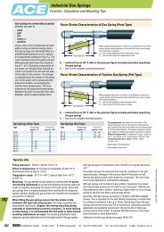
Darstellung Montagesituation <strong>LOCKED</strong><br />
1. Druckluft anschließen.<br />
2. Richtigen Druckwert beachten.<br />
3. Richtigen Druckluftwert<br />
einstellen.<br />
<strong>LOCKED</strong>-<strong>Serie</strong> <strong>PL</strong>/<strong>PL</strong>K <strong>und</strong> <strong>SL</strong>/<strong>SL</strong>K<br />
Betriebsanleitung<br />
4. System ist ohne<br />
Druck nicht montierbar.<br />
5. System ist nur mit<br />
Luftdruck > 4 bar<br />
montierbar.<br />
6. Verwenden Sie 12.9<br />
Schrauben. Schrauben<br />
ausrichten, eindrehen,<br />
anziehen, jedoch<br />
noch nicht festziehen.<br />
7. Druckluft wegnehmen, das System richtet sich aus,<br />
Schrauben jetzt mit definierten Momenten (Tabelle 1)<br />
festziehen, Vorgang evtl. in mehreren Schritten<br />
durchführen.<br />
8. Überprüfen Sie, ob das System frei beweglich ist,<br />
evtl. Schritt 6 <strong>und</strong> 7 wiederholen.<br />
<strong>LOCKED</strong>-<strong><strong>Serie</strong>s</strong> <strong>PL</strong>/<strong>PL</strong>K <strong>and</strong> <strong>SL</strong>/<strong>SL</strong>K<br />
Operating Instructions<br />
Illustration of Mounting Procedure <strong>LOCKED</strong><br />
1. Connect compressed air.<br />
2. Check that correct air pressure is present.<br />
3. Set the correct compressed<br />
air values.<br />
4. System cannot be<br />
mounted without<br />
pressure.<br />
5. To mount the<br />
system requires an<br />
air pressure > 4 bar.<br />
6. Use 12.9 screws; align<br />
system, screw down<br />
screws finger tight<br />
but do not tighten.<br />
7. Vent compressed air, the system will align itself,<br />
tighten screws to the required torque setting (table 1),<br />
process should be conducted gradually.<br />
8. Check if the system moves freely, steps 6 <strong>and</strong> 7 may<br />
have to be repeated.
<strong>LOCKED</strong>-<strong>Serie</strong> P<br />
Betriebsanleitung<br />
Modellvarianten <strong>LOCKED</strong>-<strong>Serie</strong> P<br />
<strong>LOCKED</strong>-P Klemmelemente werden in verschiedenen<br />
Größen für unterschiedliche Pneumatikzylinder geliefert<br />
<strong>und</strong> sind modular aufgebaut.<br />
Die einzelnen Versionen unterscheiden sich wie folgt:<br />
● Anzahl der Klemmmodule zwischen eins (St<strong>and</strong>ard)<br />
<strong>und</strong> drei<br />
● unterschiedliche Ausführung der Klemmhülse in<br />
Abhängigkeit vom Stangendurchmesser<br />
● unterschiedliche Membrantechnik abhängig vom<br />
spezifizierten Betriebsdruck<br />
● unterschiedliche Ober- <strong>und</strong> Untermontageplatten<br />
Wichtige Hinweise<br />
Diese Betriebsanleitung dient zur störungsfreien Nutzung<br />
der ACE <strong>LOCKED</strong>-P Klemmelemente <strong>und</strong> ist Vorraussetzung<br />
für die Erfüllung eventueller Gewährleistungsansprüche.<br />
Bitte lesen Sie deshalb vor Gebrauch der Klemmelemente<br />
unbedingt diese Betriebsanleitung.<br />
Die im Katalog angegebenen Grenzwerte, z. B. für Drücke,<br />
Kräfte, Momente <strong>und</strong> Temperaturen, sind einzuhalten.<br />
Sorgen Sie für ordnungsgemäß aufbereitete Druckluft.<br />
Behalten Sie die einmal gewählte Zusammensetzung des<br />
Mediums über die gesamte Betriebsdauer bei.<br />
Berücksichtigen Sie die vorherrschenden Umweltbedingungen.<br />
Einbau <strong>und</strong> Inbetriebnahme darf nur durch qualifiziertes<br />
Fachpersonal gemäß der vorliegenden Betriebs- <strong>und</strong><br />
Einbauanleitung erfolgen.<br />
Verwendung<br />
Die Klemmelemente der <strong>LOCKED</strong>-P <strong>Serie</strong> dienen vorwiegend<br />
zur Klemmung von Kolbenstangen an Druckluftzylindern<br />
gemäß ISO 6431<br />
<strong>LOCKED</strong>-P Klemmelemente können auch zur Klemmung<br />
<strong>and</strong>erer Maschinenelemente verwendet werden. Dies ist<br />
in jedem Fall nur nach Freigabe von ACE möglich.<br />
Die Klemmelemente erzeugen ihre Klemmkraft über einen<br />
Federspeicher <strong>und</strong> die Lösung der Klemmung erfolgt<br />
pneumatisch. Sonderlösungen, bei denen mit Luft geklemmt<br />
wird, sind möglich.<br />
Es sind sowohl die Schaltzeiten der elektronischen <strong>und</strong><br />
pneumatischen Steuerungen als auch die Reaktionszeit<br />
der <strong>LOCKED</strong>-P Type zu beachten.<br />
Sicherheitshinweise<br />
Je nach Verwendungszweck der Klemmelemente kann<br />
Gefahr entstehen durch:<br />
● falsch eingestellten Betriebsdruck<br />
Die meisten Pneumatikzylinder können mit Luftdrücken<br />
bis 10 bar betrieben werden. Die <strong>LOCKED</strong>-P Typen sind<br />
je nach Ausführungsart jedoch nur für 4 bzw. 6 bar ausgelegt.<br />
Stellen Sie durch geeignete Versiegelungen,<br />
Sicherheitshinweise <strong>und</strong>/oder Verriegelungsmechanismen<br />
sicher, dass der Benutzer Pneumatikzylinder <strong>und</strong><br />
<strong>LOCKED</strong>-P ausschließlich gemäß der Spezifikation <strong>und</strong><br />
definierten Haltekraft der Klemmung betreibt. Bei Überschreiten<br />
der zulässigen Betriebsdrücke erlischt die<br />
Gewährlistung seitens ACE.<br />
● Quetschung bei Montage durch ungesicherte<br />
Anschlusskonstruktionen<br />
● Verletzungen durch nicht sachgemäße Pneumatikverbindungen<br />
● Störungen der Pneumatikversorgung, z. B. durch<br />
Druckschwankungen<br />
● falsch eingestellten Betriebsdruck, siehe Kapitel<br />
Gewährleistung<br />
● lose Befestigungsschrauben<br />
● Nichtbeachten der Informations- <strong>und</strong> Warneinrichtungen<br />
bei der Montage bzw. Inbetriebnahme<br />
Model Designs <strong>LOCKED</strong>-<strong><strong>Serie</strong>s</strong> P<br />
<strong>LOCKED</strong>-P clamping elements in modular concept are<br />
available in different sizes for various pneumatic cylinders.<br />
The individual designs differ as follows:<br />
● Number of clamping modules vary between one<br />
(st<strong>and</strong>ard) <strong>and</strong> three<br />
● Different construction of clamping sleeve depending on<br />
rod diameter<br />
● Different membrane technology depending on specified<br />
operating pressure<br />
● Different upper <strong>and</strong> lower mounting plates<br />
<strong>LOCKED</strong>-<strong><strong>Serie</strong>s</strong> P<br />
Operating Instructions<br />
Important Notes<br />
This operating manual serves to ensure the trouble-free<br />
use of the ACE <strong>LOCKED</strong>-P clamping elements <strong>and</strong> is a prerequisite<br />
for the compliance to possible warranty claims.<br />
Please read this operating manual prior to using the<br />
clamping elements.<br />
The limit values, i.e. for pressures, forces, torques<br />
<strong>and</strong> temperatures, quoted in this catalogue should be<br />
adhered to.<br />
Provide for properly prepared compressed air. Keep the<br />
initially chosen composition of the medium for the total<br />
duration of operation. Consider the prevailing environmental<br />
conditions.<br />
Installation <strong>and</strong> initial operation may only be made by<br />
qualified personnel <strong>and</strong> according to available operating<br />
<strong>and</strong> mounting manuals.<br />
Usage<br />
The clamping elements of the <strong>LOCKED</strong>-P <strong><strong>Serie</strong>s</strong> are predominantly<br />
used for the clamping of piston rods on air<br />
cylinders according to ISO 6431.<br />
<strong>LOCKED</strong>-P clamping elements can also be used to clamp<br />
other machine elements. Suitability should be verified<br />
with ACE before proceeding. Clamping elements generate<br />
their clamping force via a spring-brake actuator <strong>and</strong><br />
the release occurs by venting the air. Special solutions<br />
where the clamping occurs due to air pressure are<br />
available on request.<br />
The response times of electronic <strong>and</strong> pneumatic controls,<br />
as well as the reaction time of the <strong>LOCKED</strong>-P Type, are to<br />
be observed.<br />
Safety Advice<br />
Dangers can arise depending on the following factors:<br />
● Incorrectly set operating pressure.<br />
Most pneumatic cylinders can be operated with compressed<br />
air up to 10 bar. The <strong>LOCKED</strong>-P types can,<br />
depending on the model, be operated with only 4 or 6 bar.<br />
Appropriate sealing, safety advice <strong>and</strong>/or locking mechanisms<br />
must ensure that the user operates pneumatic<br />
cylinders <strong>and</strong> <strong>LOCKED</strong>-P devices exclusively according<br />
to the specifications <strong>and</strong> the clamping’s defined holding<br />
forces. ACE does not warranty the products if the permissible<br />
operating pressure is exceeded.<br />
● Unsecured connecting structures can lead to damage<br />
when mounting.<br />
● Incorrect pneumatic connections can lead to injuries.<br />
● Failures of the pneumatic supply can occur, for example,<br />
due to pressure fluctuation.<br />
● For wrongly set operating pressure see chapter<br />
“Warranty”.<br />
● Lose mounting screws.<br />
● Disregarding the information <strong>and</strong> warnings when<br />
setting up or starting up the machine.
<strong>LOCKED</strong>-<strong>Serie</strong> P<br />
Betriebsanleitung<br />
Gewährleistung<br />
Bauartbedingt ist bei <strong>LOCKED</strong>-P Typen der Toleranzbereich<br />
(Toleranz, Zylinderform) zwischen Achse/Welle <strong>und</strong><br />
Klemmung innerhalb des durch die Anwendung definierten<br />
Bereichs einzuhalten. Eine Abweichung hiervon kann<br />
im Dauerbetrieb zu einer Schädigung der <strong>LOCKED</strong>-P<br />
Type oder zu geringeren Haltekräften führen. Es ist<br />
besonders darauf zu achten, dass der <strong>LOCKED</strong>-P im<br />
geöffneten Zust<strong>and</strong> die Achse bzw. Welle völlig frei gibt.<br />
Umgebungsbedingungen<br />
Umgebungstemperatur min. 10°C <strong>und</strong> max. 45°C, pneumatischer<br />
Betriebsdruck min. 5,5 bar <strong>und</strong> max. 6 bar<br />
(4 bar bei Spezialausführung), Betrieb nur mit getrockneter<br />
gefilterter Luft.<br />
Es gilt eine Gewährleistung von 24 Monaten nach<br />
Lieferung, höchstens aber eine Zyklusanzahl von 1 000 000<br />
Klemmungen (keine Notfall- oder Bremsklemmungen).<br />
Der K<strong>und</strong>e muss im Gewährleistungsfall die tatsächliche<br />
Anzahl der Klemmungen in geeigneter Form nachweisen.<br />
Das Klemmelement dient nicht zum Sichern von Lasten.<br />
Die bestimmungsgemäße Verwendung der Klemmelemente<br />
setzt voraus, dass diese nur im Rahmen der durch<br />
die technische Spezifikation angegebenen Möglichkeiten<br />
eingesetzt werden. Andere Verwendungen schließen jegliche<br />
weitere Leistungen aus.<br />
Transport, Lagerung <strong>und</strong> Zwischenlagerung<br />
Die Klemmelemente sollten im geölten Zust<strong>and</strong> <strong>und</strong> in<br />
der von ACE ausgewählten Verpackung gelagert bzw.<br />
zwischengelagert werden.<br />
Typenbezeichnung<br />
Die eingravierte <strong>Serie</strong>nnummer dient der Identifikation<br />
<strong>und</strong> Rückverfolgbarkeit des jeweiligen Klemmelementes.<br />
Alle Gewährleistungsansprüche erlöschen durch das Entfernen<br />
oder Unkenntlichmachen der Typenbezeichnung<br />
<strong>und</strong> der <strong>Serie</strong>nnummer. Die Typenbezeichnung befindet<br />
sich bei <strong>LOCKED</strong>-P Klemmelementen auf der Zwischenplatte<br />
unter den Druckluft <strong>und</strong> Sensoranschlüssen.<br />
Nur komplett zusammengebaute Klemmelemente werden<br />
durch die Gewährleistung abgedeckt. Eine Demontage<br />
bzw. Ausein<strong>and</strong>erbauen der Klemmung durch den K<strong>und</strong>en<br />
wird untersagt.<br />
Eine Reparatur bzw. Prüfung der Klemmelemente muss<br />
durch ACE erfolgen.<br />
Besonderheiten <strong>LOCKED</strong>-P<br />
Die Funktion der Klemmelemente hängt von der Kombination<br />
<strong>LOCKED</strong>-P zur Klemmfläche ab. Bei Verwendung<br />
an einem ISO VDMA Zylinder sind daher die Eigenschaften<br />
der Kolbenstange wichtige Einflussgrößen.<br />
Die Klemmelemente sind in ihrer St<strong>and</strong>artausführung<br />
für die folgenden Bedingungen optimiert: Durchmesser<br />
„Stangendurchmesser mit Toleranzfeld h9“, Werkstoff<br />
Kolbenstange (herstellerabhängig) z.B. CF63 oder<br />
16MnCr5. Im Idealfall sollte die Stange oberflächengehärtet<br />
sein, um die Lebensdauer zu erhöhen. Die optionalen<br />
Endlagenschalter sind nicht geeignet um die Funktion zu<br />
überprüfen <strong>und</strong> dienen ausschließlich zur Kontrolle des<br />
Schaltzust<strong>and</strong>es. Im Falle eines Defektes kann das<br />
Klemmelement trotz gegenteiliger Anzeige geöffnet sein.<br />
Montage <strong>LOCKED</strong>-P<br />
Rote Verschlusskappe <strong>und</strong> Verschlussteile für Sensoranschlüsse<br />
bei Bedarf entfernen. An dem mit „open“<br />
bezeichneten Anschluss entsprechende Pneumatikverbindung<br />
anbringen. Das Klemmelement muss zur Montage,<br />
je nach Ausführung, mit 4 bar bzw. 6 bar beaufschlagt<br />
werden (Bild 1). Ohne Druck ist das System nicht montierbar.<br />
Nun kann das Klemmelement über die Stange<br />
geführt werden. Das Element in seiner vorgesehenen<br />
Position ausrichten <strong>und</strong> mit reduziertem Anzugsmoment<br />
anschrauben (Bild 2). Den Luftdruck auf 0 Bar reduzieren<br />
bis die <strong>LOCKED</strong>-P Type sich auf der Achse bzw. Welle<br />
zentriert, Schrauben eventuell wieder etwas lösen, um<br />
das Ausrichten zu ermöglichen. Nachdem das Klemmelement<br />
in seiner vorgesehenen Position zentriert ist, die<br />
Befestigungsschrauben mit definiertem Anzugsmoment<br />
(Tabelle 1) anziehen. Optional können zur Kontrolle des<br />
Schaltzust<strong>and</strong>es Endschalter mit Gewinde M8 in die vorgesehenen<br />
Bohrungen eingeschraubt werden.<br />
Abschließende zwingend durchzuführende Prüfungen<br />
Prüfen Sie das System zunächst mit geringeren Kräften.<br />
Evtl. Vorkehrungen treffen für den Fall, dass aufgr<strong>und</strong><br />
fehlerhafter Montage die Haltekräfte zu gering sind.<br />
Sollten Sie keine einw<strong>and</strong>freie Funktion erreichen,<br />
kontaktieren Sie ACE.<br />
Nach Anschluss des Systems fahren Sie einige<br />
Probezyklen, um die Funktionsfähigkeit abschließend zu<br />
prüfen.<br />
<strong>LOCKED</strong>-<strong><strong>Serie</strong>s</strong> P<br />
Operating Instructions<br />
Warranty<br />
Due to the <strong>LOCKED</strong>-P Type design, tolerances (tolerance,<br />
cylinder form) between the axis/spindle <strong>and</strong> clamping<br />
within the application must be adhered to. Deviations<br />
during continuous operation can lead to damages of the<br />
<strong>LOCKED</strong>-P Type or to lower holding forces. It must be<br />
made sure that when opened, the <strong>LOCKED</strong>-P releases the<br />
axis or spindle completely.<br />
Ambient Condition<br />
Ambient temperature min. 10°C <strong>and</strong> max. 45°C, pneumatic<br />
operating pressure min. 5,5 bar max. 6 bar (4 bar<br />
for special designs), operation only with dry, filtered air.<br />
The warranty is valid for 24 months after delivery, with a<br />
maximum of 1 000 000 clamping cycles (no emergency or<br />
brake clamping). The customer must show suitable proof<br />
for the actual number of clamping operations in the case<br />
of a warranty claim.<br />
The clamping element does not serve to secure loads.<br />
The application of these clamping elements assumes that<br />
they are only used according to their stated specifications.<br />
Other usage is strictly prohibited <strong>and</strong> debars any<br />
further services.<br />
Transport, Storage <strong>and</strong> Interim Storage<br />
The clamping elements should be stored oiled <strong>and</strong> in<br />
packaging chosen by ACE.<br />
Model Identification<br />
The engraved serial number serves the identification traceability<br />
of the individual clamping elements. All warranty<br />
claims expire when these IDs are removed or made<br />
illegible. The model identification for the <strong>LOCKED</strong>-P clamping<br />
element is located on the inner plate <strong>und</strong>er the connections<br />
for compressed air <strong>and</strong> sensors.<br />
Only completely assembled clamping elements are covered<br />
by the warranty. Disassembling or dismounting the<br />
clamps by the customer is strictly prohibited.<br />
Repairs or service of the clamping elements must be performed<br />
by ACE.<br />
Requirements for the <strong>LOCKED</strong>-P<br />
The function of the clamping elements relates to the<br />
<strong>LOCKED</strong>-P combination with the clamping area. When<br />
using on an ISO VDMA cylinder, the characteristics of the<br />
piston rod are therefore important factors. The clamping<br />
elements are optimized in their st<strong>and</strong>ard design for the<br />
following requirements: Diameter ”rod diameter with<br />
tolerance zone h9“, material piston rod (depending on<br />
manufacturer) for example, CF63 or 16MnCr5. Ideally the<br />
rod should be surface-hardened to increase its lifetime.<br />
The optional limit switches are not suited to check the<br />
function <strong>and</strong> serve exclusively to check the condition of<br />
the switch status. In case of a defect, the clamping element<br />
can be released despite a contrary signal.<br />
Mounting the <strong>LOCKED</strong>-P<br />
Remove the red locking cap <strong>and</strong> locking parts for the<br />
sensor connections if required. Mount the appropriate<br />
pneumatic connection to the link labeled “open”. The<br />
clamping element must be filled with 4 bar or 6 bar<br />
depending on the model (picture 1). The system cannot<br />
be mounted without pressure. The clamping element<br />
can now be guided over the rod. Align the element in its<br />
designated position <strong>and</strong> screw on using a reduced tightening<br />
torque (picture 2). Reduce the air pressure to 0 bar<br />
until the <strong>LOCKED</strong>-P type centers on the axis, i.e. spindle;<br />
the screws may require loosening to enable exact<br />
alignment. After the clamping element is centered in its<br />
required position, the fastening screws are to be tightened<br />
with the necessary tightening torque (table 1). Optional<br />
end switches thread size M8 can be screwed into the<br />
intended bores to check the switch condition.<br />
M<strong>and</strong>atory Final Checks<br />
First check the system with light forces; safety procedures<br />
should be implemented in case the holding forces are<br />
too low due to incorrect mounting.<br />
Please contact ACE if the device does not function<br />
correctly.<br />
Operate a few test cycles after mounting the system to<br />
finally check the system’s functional capability.
<strong>LOCKED</strong>-<strong>Serie</strong> P<br />
Betriebsanleitung<br />
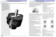
<strong>LOCKED</strong>-P ist nur mit Druckluft montierbar<br />
Schrauben per H<strong>and</strong> eindrehen.<br />
Druck wegnehmen <strong>und</strong> mit<br />
definiertem Anzugsmoment<br />
über Kreuz anziehen.<br />
Überprüfen, ob die Stange<br />
frei ist. Eventuell die oben<br />
aufgeführten Schritte<br />
wiederholen.<br />
Abschließend die Endlagenschalter<br />
zur Zust<strong>and</strong>süberwachung<br />
durch erforderliche<br />
Einschraubtiefe einstellen.<br />
Hinweise <strong>und</strong> Empfehlungen<br />
Das Pneumatikventil (3/2 Wegeventil, Nenngröße mindestens<br />
G 1/8) in der Nähe des Klemmelementes montieren<br />
mit Ø 6 bzw. Ø 8 mm Schlauch verbinden. Zur Verkürzung<br />
der Reaktionszeit empfiehlt sich die Verwendung<br />
eines Schnellentlüftungsventils.<br />
Wichtig: Je länger die Leitungswege desto länger die entsprechenden<br />
Reaktionszeiten<br />
Empfohlene Anzugsmomente <strong>LOCKED</strong>-P<br />
Achten Sie auf einem verzugsfreien Einbau <strong>und</strong> der Einhaltung<br />
der zulässigen Belastungen laut Katalog.<br />
Zur Befestigung sind Schrauben der Festigkeitsklasse 8.8<br />
zu verwenden. Schrauben mit den unten vorgeschriebenen<br />
Anzugsmomenten anziehen. Die Werte gelten für alle<br />
Versionen, unabhängig von der Modulzahl.<br />
Type Anzugsmoment<br />
PN 63 5 Nm<br />
PN 80 10 Nm<br />
PN125 35 Nm<br />
Wartung <strong>und</strong> Pflege<br />
Reinigen Sie Verschmutzungen auf <strong>und</strong> neben den<br />
Klemmflächen regelmäßig mit einem weichen Lappen<br />
bzw. mit Druckluft. Verwenden Sie niemals fetthaltige<br />
oder schmierende Hilfsmittel, diese können die jeweiligen<br />
Klemmmomente reduzieren.<br />
Zulässige Reinigungsmittel sind alle Werkstoffschonenden<br />
Medien.<br />
Prüfen Sie die Klemmflächen auf Verschleiß bzw.<br />
Materialabrieb.<br />
<strong>LOCKED</strong>-<strong><strong>Serie</strong>s</strong> P<br />
Operating Instructions<br />
<strong>LOCKED</strong>-P is only mountable with compressed air<br />
Screws must be fitted h<strong>and</strong><br />
tight.<br />
Vent air pressure <strong>and</strong><br />
tighten screws, diametrically<br />
opposed, to the required<br />
torque.<br />
Check if the rod is free.<br />
Repeat the above steps if<br />
necessary.<br />
Finally adjust the end position<br />
switch via the required<br />
thread reach.<br />
Notes <strong>and</strong> Recommendations<br />
Mount the pneumatic valve (3/2 direction control valve,<br />
nominal size at least G 1/8) near the clamping elements<br />
<strong>and</strong> connect with a Ø 6 or Ø 8 mm hose. To shorten the<br />
response time, it is recommended to use a quick air-vent<br />
valve.<br />
Important: The longer the lines, the longer are the corresponding<br />
response times.<br />
Recommended Tightening Torque <strong>LOCKED</strong>-P<br />
To ensure a quick set-up <strong>and</strong> adherence to the permissible<br />
loads according to catalogue.<br />
Screws of the strength category 8.8 are to be used for<br />
mounting. Fasten screws with the tightening torques<br />
listed below. The values are for all models, independent<br />
of the number of modules.<br />
Model Max. Torque<br />
PN 63 5 Nm<br />
PN 80 10 Nm<br />
PN125 35 Nm<br />
Maintenance <strong>and</strong> Care<br />
Clean surfaces on <strong>and</strong> next to the clamping areas regularly<br />
with a soft cloth or with compressed air. Never use<br />
fatty or greasy solvents; these can reduce the individual<br />
clamping torques.<br />
Permissible cleanings agents are all materials with a<br />
gentle media.<br />
Check the clamping areas for wear <strong>and</strong> tear or material<br />
abrasion.
Industrie-Stoßdämpfer<br />
Verkaufs- <strong>und</strong> Lieferbedingungen<br />
St<strong>and</strong>: Mai 2006<br />
1. Allgemeines<br />
Allen Kauf- <strong>und</strong> Lieferverträgen des Verkäufers liegen die nachfolgenden Bedingungen<br />
zugr<strong>und</strong>e, die durch Auftragserteilung <strong>und</strong> Annahme der Lieferung als anerkannt<br />
gelten. Abweichende Bedingungen des Bestellers gelten nur bei ausdrücklicher<br />
schriftlicher Anerkennung durch den Verkäufer. Die Einkaufsbedingungen des<br />
Auftraggebers haben für den Verkäufer keine Gültigkeit. Für Werkstoffe gelten die<br />
DIN-Normen oder h<strong>and</strong>elsübliche Begriffe <strong>und</strong> die anerkannten Richtlinien der<br />
Industriefachverbände.<br />
Der Verkäufer behält sich an Mustern, Kostenvoranschlägen, Zeichnungen <strong>und</strong> ähnlichen<br />
Informationen körperlicher <strong>und</strong> unkörperlicher Art, auch in elektronischer Form,<br />
Eigentums- <strong>und</strong> Urheberrechte vor. Sie dürfen Dritten nicht zugänglich gemacht werden.<br />
Der Verkäufer verpflichtet sich, vom Käufer als vertraulich bezeichnete<br />
Informationen <strong>und</strong> Unterlagen nur mit Zustimmung Dritten zugänglich zu machen.<br />
2. Vertragsabschluss<br />
Angebote sind freibleibend. Die Annahme einer Bestellung kann nur durch schriftliche<br />
Bestätigung seitens des Verkäufers erfolgen. Von diesen Bedingungen abweichende<br />
Vereinbarungen bedürfen der Schriftform. Die Änderung dieser Schriftformvereinbarung<br />
kann ebenfalls nur schriftlich erfolgen.<br />
3. Preise<br />
Preise gelten gr<strong>und</strong>sätzlich ab Werk, ausschließlich der Kosten der Verpackung, des<br />
Transports <strong>und</strong> Transportrisikos. Sind Festpreise nicht ausdrücklich vereinbart, so gelten<br />
die jeweils am Tage der Lieferung gültigen Listenpreise. Berechnung <strong>und</strong><br />
Bezahlung erfolgen in € zzgl. der gesetzlichen Mehrwertsteuer.<br />
4. Lieferung<br />
Liefertermine <strong>und</strong> Lieferfristen, die verbindlich oder unverbindlich vereinbart werden<br />
können, sind schriftlich anzugeben. Lieferfristen gelten vom Tage der kaufmännischen<br />
<strong>und</strong> technischen Klarstellung des Auftrages an. Die Einhaltung der Lieferfrist setzt den<br />
rechtzeitigen Eingang sämtlicher vom Auftraggeber zu liefernden Unterlagen, eine<br />
rechtzeitige Klarstellung durch den Auftraggeber <strong>und</strong> die Einhaltung der vereinbarten<br />
Zahlungsbedingungen voraus.<br />
Der Käufer kann drei Wochen nach Überschreiten eines unverbindlichen Liefertermins<br />
oder einer unverbindlichen Lieferfrist den Verkäufer auffordern zu liefern. Mit<br />
dem Zugang der Aufforderung kommt der Verkäufer in Verzug.<br />
Hat der Käufer Anspruch auf Ersatz eines Verzugschadens, beschränkt sich dieser bei<br />
leichter Fahrlässigkeit des Verkäufers auf höchstens 5 % des vereinbarten<br />
Kaufpreises. Will der Käufer darüber hinaus vom Vertrag zurücktreten <strong>und</strong>/oder<br />
Schadensersatz statt der Leistung verlangen, muss er dem Verkäufer nach Ablauf der<br />
Dreiwochenfrist eine angemessene Frist zur Lieferung setzen. Hat der Käufer Anspruch<br />
auf Schadensersatz statt der Leistung, beschränkt sich der Anspruch bei leichter<br />
Fahrlässigkeit auf höchstens 25 % des vereinbarten Kaufpreises.<br />
Wird ein verbindlicher Liefertermin oder eine verbindliche Lieferfrist überschritten,<br />
kommt der Verkäufer bereits mit Überschreiten des Liefertermins oder der Lieferfrist<br />
in Verzug. Die vorstehenden Haftungsbeschränkungen gelten in diesem Fall entsprechend.<br />
Höhere Gewalt oder beim Verkäufer oder dessen Lieferanten eintretende Betriebsstörungen,<br />
die den Verkäufer ohne eigenes Verschulden vorübergehend daran hindern,<br />
den Kaufgegenst<strong>and</strong> zum vereinbarten Termin oder innerhalb der vereinbarten<br />
Frist zu liefern, verändern die in dieser Vorschrift genannten Termine <strong>und</strong> Fristen um<br />
die Dauer der durch diese Umstände bedingten Leistungsstörungen. Führen entsprechende<br />
Störungen zu einem Leistungsaufschub von mehr als zwei Monaten,<br />
kann der Käufer vom Kaufvertrag zurücktreten. Andere Rücktrittsrechte bleiben<br />
davon unberührt.<br />
5. Erfüllungsort für alle sich unmittelbar oder mittelbar aus diesem Vertragsverhältnis<br />
ergebenen Verpflichtungen, einschließlich der Zahlungspflicht ist der Sitz des Verkäufers.<br />
6. Zahlungen<br />
Die Zahlungsbedingungen ergeben sich aus der Auftragsbestätigung bzw. der Rechnung.<br />
Eine Verrechnung durch Gegenforderungen jeglicher Art ist ausgeschlossen,<br />
soweit es sich dabei nicht um rechtskräftige oder unbestrittene Forderungen h<strong>and</strong>elt.<br />
Zahlungen dürfen durch evtl. Gegenforderungen nicht zurückgehalten werden. Bei<br />
Nichteinhaltung der Zahlungsfrist kommt der Käufer ohne Mahnung in Verzug. Die<br />
Annahme von Wechseln erfolgt nur nach vorheriger Vereinbarung.<br />
Zahlungen durch Schecks oder Wechsel gelten erst nach Einlösung <strong>und</strong> Gutschrift<br />
bei den Geldinstituten des Verkäufers als vollzogen. Diskontspesen trägt der Auftraggeber.<br />
Bei Zielüberschreitungen ist der Verkäufer berechtigt Verzugszinsen in<br />
Höhe von 8 % über dem Basiszinssatz zu verlangen. Bei Zahlungseinstellung, Stellung<br />
eines Antrages auf Eröffnung des Insolvenzverfahrens des Auftraggebers sind alle<br />
Rechnungen des Verkäufers fällig, zugleich verfallen alle Rabatte.<br />
7. Eigentumsvorbehalt<br />
Der Verkäufer behält sich das Eigentum an den Liefergegenständen einschließlich<br />
sämtlicher Nebenforderungen bis zum Eingang aller Zahlungen aus dem Liefervertrag<br />
vor. Werden durch den Auftraggeber Waren an Dritte veräußert, so tritt der<br />
Auftraggeber schon bei Abschluss des Liefervertrages seine Ansprüche aus dem<br />
Verkaufsvertrag an den Dritten bis zur vollständigen Erfüllung seiner Zahlungsverpflichtungen<br />
aus dem Liefervertrag an den Verkäufer ab (verlängerter Eigentumsvorbehalt).<br />
Solange die Liefergegenstände unter Eigentumsvorbehalt des Verkäufers<br />
stehen, dürfen diese vom Auftraggeber nur mit schriftlicher Zustimmung des Verkäufers<br />
verpfändet oder zur Sicherheit übereignet werden. Der Auftraggeber hat<br />
bei Pfändung <strong>und</strong> Beschlagnahme der Liefergegenstände den Verkäufer per eingeschriebenen<br />
Brief darüber zu unterrichten. Die Geltendmachung des Eigentumsvorbehaltes<br />
durch den Verkäufer gilt nicht als Rücktritt vom Vertrag. Der Auftraggeber<br />
ist nicht berechtigt, seine Ansprüche aus dem Liefervertrag ohne schriftliche<br />
Zustimmung des Verkäufers an einen Dritten abzutreten. Sollte durch den vorbezeichneten<br />
verlängerten Eigentumsvorbehalt eine Übersicherung des Verkäufers von mehr<br />
als 20 % über der zu sichernden Forderung eintreten, so ist der Auftraggeber berechtigt,<br />
die Rückabtretung der darüber hinausgehenden Forderung zu verlangen.<br />
8. Gewährleistung, Mängelrügen<br />
Offensichtliche Mängel müssen dem Verkäufer unverzüglich nach Lieferung, spätestens<br />
innerhalb von einer Woche, in jedem Falle aber vor der Verarbeitung oder dem<br />
Einbau schriftlich gemeldet werden, <strong>and</strong>ernfalls ist die Geltendmachung eines<br />
Gewährleistungsanspruchs ausgeschlossen. Zur Fristwahrung genügt die rechtzeitige<br />
Absendung.<br />
Dem Verkäufer ist Gelegenheit zur Nachprüfung an Ort <strong>und</strong> Stelle zu geben. Bei<br />
berechtigter Mängelrüge leistet der Verkäufer nach seiner Wahl Gewähr durch<br />
Nachbesserung oder Ersatzlieferung.<br />
Schlägt die Nacherfüllung fehl, kann der Käufer nach seiner Wahl Herabsetzung der<br />
Vergütung (Minderung) oder Rückgängigmachung des Vertrages (Rücktritt) verlangen.<br />
Bei einer nur geringfügigen Vertragswidrigkeit, insbesondere bei nur geringfügigen<br />
Mängeln, steht dem Käufer jedoch kein Rücktrittsrecht zu.<br />
Wählt der Käufer wegen eines Rechts- oder Sachmangels nach gescheiterter Nacherfüllung<br />
den Rücktritt vom Vertrag, steht ihm daneben kein Schadensersatzanspruch<br />
wegen des Mangels zu.<br />
Wählt der Käufer nach gescheiterer Erfüllung Schadensersatz, verbleibt die Ware<br />
beim Käufer, wenn ihm dies zumutbar ist. Der Schadensersatz beschränkt sich auf die<br />
Differenz zwischen dem Kaufpreis <strong>und</strong> dem Wert der mangelhaften Sache. Dies gilt<br />
nicht, wenn der Verkäufer die Vertragsverletzung arglistig verursacht hat.<br />
Als Beschaffenheit der Ware gilt gr<strong>und</strong>sätzlich nur die Produktbeschreibung des<br />
Verkäufers als vereinbart. Öffentliche Äußerungen, Anpreisungen oder Werbung<br />
des Herstellers stellen daneben keine vertragsgemäße Beschaffenheitsangabe der<br />
Ware dar.<br />
Erhält der Käufer eine mangelhafte Montageanleitung, ist der Verkäufer lediglich zur<br />
Lieferung einer mangelfreien Montageanleitung verpflichtet <strong>und</strong> dies auch nur dann,<br />
wenn der Mangel der Montageanleitung der ordnungsgemäßen Montage entgegensteht.<br />
Die Gewährleistungsfrist beträgt zwei Jahre <strong>und</strong> beginnt mit Fertigstellung. Umtausch<br />
<strong>und</strong> Rücknahme von Sonderanfertigungen sind gr<strong>und</strong>sätzlich ausgeschlossen. Für<br />
nicht von dem Verkäufer hergestellte <strong>und</strong> bearbeitete Teile gelten die Werksbedingungen<br />
des Herstellerwerkes, die vom Besteller bei dem Verkäufer jederzeit eingesehen<br />
werden können. Konstruktions- <strong>und</strong> Einbauteile werden nach dem<br />
jeweils neuesten St<strong>and</strong> geliefert. Gewährleistungen auf Verschleißteile sind den<br />
jeweiligen Montage- <strong>und</strong> Bedienungsanleitungen zu entnehmen.<br />
9. Haftung<br />
Hat der Verkäufer aufgr<strong>und</strong> der gesetzlichen Bestimmungen nach Maßgabe dieser<br />
Bedingungen für einen Schaden aufzukommen, der leicht fahrlässig verursacht<br />
wurde, so haftet der Verkäufer beschränkt.<br />
Die Haftung besteht nur bei Verletzung vertragswesentlicher Pflichten <strong>und</strong> ist auf den<br />
bei Vertragabschluss vorhersehbaren typischen, unmittelbaren Schaden beschränkt,<br />
höchstens jedoch auf 25 % des vereinbarten Kaufpreises. Diese Beschränkung gilt<br />
nicht bei Verletzung von Leben, Körper <strong>und</strong> Ges<strong>und</strong>heit, ferner bleibt eine etwaige<br />
Haftung des Verkäufers bei arglistigem Verschweigen des Mangels oder aus der<br />
Übernahme einer Garantie oder eines Beschaffungsrisikos <strong>und</strong> nach dem Produkthaftungsgesetz<br />
unberührt.<br />
Soweit der Schaden durch eine vom Käufer für den betreffenden Schadenfall abgeschlossene<br />
Versicherung (ausgenommen Summenversicherung) gedeckt ist, haftet<br />
der Verkäufer für die damit verb<strong>und</strong>enen Nachteile des Käufers, z. B. höhere Versicherungsprämien<br />
oder Zinsnachteile bis zur Schadensregulierung durch die<br />
Versicherung.<br />
Die Haftung wegen Lieferverzuges ist abschließend in Ziff. 4 geregelt.<br />
10. Anwendbares Recht, Gerichtsst<strong>and</strong><br />
Für alle Rechtsbeziehungen zwischen dem Lieferer <strong>und</strong> Besteller gilt ausschließlich<br />
das Recht der B<strong>und</strong>esrepublik Deutschl<strong>and</strong>. Gerichtsst<strong>and</strong> ist das für den Sitz des<br />
Lieferers zuständige Gericht. Der Lieferer ist jedoch berechtigt, am Hauptsitz des<br />
Bestellers Klage zu erheben.<br />
ACE Industrie-Stoßdämpfer<br />
Sales Terms <strong>and</strong> Delivery Conditions<br />
As of: May 2006<br />
1. General<br />
All sales <strong>and</strong> delivery contracts of the seller are based on the following conditions,<br />
which are considered accepted to be valid by placing the order <strong>and</strong> accepting the<br />
delivery. Deviating conditions of the purchaser are only valid upon explicit written<br />
acceptance by the seller. The purchasers’ purchasing terms do not apply for the<br />
seller. For materials, DIN st<strong>and</strong>ards or commercial terms <strong>and</strong> accepted guidelines of<br />
industrial trade associations apply.<br />
The seller reserves property rights <strong>and</strong> copyrights for samples, cost estimates,<br />
drawings <strong>and</strong> similar information of material or immaterial nature, this also includes in<br />
electronic form. They must not be made accessible to third parties. The seller obligates<br />
itself to only make information <strong>and</strong> documentation marked by the purchaser as<br />
confidential accessible to third parties with its consent.<br />
2. Contract Conclusion<br />
Offers are subject to confirmation. Acceptance of an offer can only be facilitated by<br />
written confirmation by the seller. Agreements that deviate from these conditions must<br />
be in written form. Change of the agreement for the written form may also only be in<br />
writing.<br />
3. Prices<br />
Prices generally apply ex works, excluding the costs for packing, transport <strong>and</strong> transport<br />
risk. If fixed prices were not arranged explicitly, the list prices that were valid<br />
on the day of delivery apply. Calculation <strong>and</strong> payment will be in € plus statutory value<br />
added tax.<br />
4. Delivery<br />
Delivery dates <strong>and</strong> delivery periods that were arranged with or without obligation are<br />
to be specified in writing. Delivery periods become effective on the day of business<br />
<strong>and</strong> technical clarification of the order. Compliance with delivery periods requires<br />
timely receipt of all documents to be delivered by party ordering, timely clarification by<br />
party ordering <strong>and</strong> compliance with the arranged terms of payment.<br />
If a delivery date without obligation or a delivery period without obligation is exceeded<br />
by three weeks, the purchaser can request delivery from the seller. Effective with<br />
receipt of this request, the seller is considered in delay.<br />
If the purchaser is entitled to delay compensation, in cases of slight the seller’s<br />
negligence, it is limited to a maximum of 5 % of the arranged purchase price. If in<br />
addition, the seller desires to withdraw from the contract <strong>and</strong>/or to request compensation<br />
instead of delivery, it must provide the seller with a reasonable delivery deadline<br />
after expiration of the three-week-period. If the purchaser is entitled to compensation<br />
instead of delivery, in the case of slight negligence the entitlement is limited to a<br />
maximum of 25 % of the arranged purchase price.<br />
If a delivery date with obligation or delivery period with obligation is exceeded, the seller<br />
is already in delay with exceeding the delivery date of delivery period. In this case,<br />
the aforementioned liability restrictions apply accordingly.<br />
Force majeure or operational interruptions occurring with the seller or its suppliers<br />
that temporarily hinder the seller without its fault to deliver the object of purchase<br />
at the arranged date or within the arranged period change the dates <strong>and</strong> periods mentioned<br />
in this provision by the time period of the performance interruptions<br />
caused by these conditions. The purchaser can withdraw from the contract of sale if<br />
corresponding interruptions result in a performance delay of more than two months.<br />
Other withdrawal rights remain unchanged.<br />
5. Place of Fulfilment<br />
Place of fulfilment for all obligations that are a direct or indirect result of this contractual<br />
relationship, including the payment obligation, is the seller’s place of business.<br />
6. Payments<br />
The payment conditions are specified in the confirmation of order or the invoice.<br />
Offsetting against counterclaims of any type is excluded, unless the claims have been<br />
confirmed by a court of law or are <strong>und</strong>isputed. Payments must not be withheld against<br />
possible counterclaims. In the case of non-compliance with payment terms, the<br />
seller is in arrears without notification. Bills of exchange will only be accepted upon<br />
prior agreement.<br />
Payments via cheque or bill of exchange are only considered fulfilled after encashment<br />
<strong>and</strong> credit by the seller’s financial institute. Discount charges are borne by the party<br />
ordering. In case the payment target is exceeded, the seller is entitled to request<br />
default interest in the amount of 8 % above the base rate. In the event of suspension<br />
of payments, the party ordering filing a request to initiate insolvency proceedings, all<br />
the seller’s invoices are due <strong>and</strong> at the same time, all discounts become invalid.<br />
7. Retention of Title<br />
The seller reserves the right of ownership of the delivery items including all accessory<br />
claims until receipt of all payments from the delivery contract. If the party ordering<br />
sells goods to third parties, already with conclusion of the delivery contract, the<br />
ordering party assigns its claims against the third party from the sales contract until<br />
complete fulfilment of its payment obligations from the delivery contract to the seller<br />
(extended retention of title). As long as delivery items are subject to the seller’s<br />
retention of title, they must only be pledged or transferred as security by the party<br />
ordering with the seller’s written consent. In the event of seizure or confiscation of<br />
delivery items, the party ordering must notify the seller via registered letter. Assertion<br />
of the retention of title by the seller shall not be deemed as contract withdrawal. The<br />
party ordering is not entitled to assign claims from the delivery contract to third<br />
parties without written consent by the seller. If, as a result of the above described<br />
extended retention of title, excess security by the seller of more than 20 % above the<br />
claim to be secured occurs, the ordering party is entitled to request reassignment of<br />
the exceeding claim.<br />
8. Warranty, Notice of Defects<br />
Obvious defects must be notified in writing to the seller immediately upon delivery,<br />
no later than within one week, but in any case, prior to processing or installation,<br />
otherwise assertion of a warranty claim is excluded. Timely sending is considered sufficient<br />
for adherence to the time limit.<br />
The seller must be granted the opportunity for an on-site check-over. In case of a justified<br />
notice of defects, the seller shall provide at its own choice warranty through<br />
correction or compensation delivery.<br />
If the re-fulfilment fails, the purchaser can request at its own choice a reduction of<br />
payment (decrease) or rescission of the contract (withdrawal). However, in the event<br />
of only a slight lack of conformity with the contract, in particular only slight deficiencies,<br />
the purchaser is not entitled to a right of withdrawal.<br />
If the purchaser chooses, due to a legal or material deficiency after failed re-fulfilment<br />
to withdraw from the contract, it is not entitled to any additional claim for compensation<br />
due to the deficiency.<br />
If the purchaser chooses compensation after failed re-fulfilment, the goods remain<br />
with the purchaser if this is reasonable. Compensation is limited to the difference<br />
between the purchase price <strong>and</strong> the value of the deficient item. This does not apply if<br />
the seller caused the contract breach maliciously.<br />
Generally, only the seller’s product description is agreed to for the condition of the<br />
goods. Public statements, advertising or sales promotions by the manufacturer do not<br />
represent an additional contractual condition statement of the goods.<br />
If the purchaser receives deficient installation instructions the seller is only obligated<br />
to delivery of correct installation instructions <strong>and</strong> this only then if the deficiency in the<br />
installation instructions hinders proper installation.<br />
The warranty period is two years <strong>and</strong> commences with completion. Exchange <strong>and</strong><br />
return of custom-made products are always excluded. For parts that were not<br />
produced or processed by the seller, manufacturer’s conditions apply which can be<br />
viewed by the purchaser at any time at the seller’s. Construction <strong>and</strong> built-in parts are<br />
delivered according to the respective state-of-the-art. Note that potential damage<br />
caused by wearing parts is referred to in the respective assembly <strong>and</strong> operating<br />
instructions.<br />
9. Liability<br />
If, based on legal provisions according to these conditions, the seller is liable to compensate<br />
for a damage that was caused slightly negligently, the seller is limitedly liable.<br />
The liability only applies for violation of important contractual liabilities <strong>and</strong> is limited<br />
to typical, direct damages that were predictable at contract conclusion <strong>and</strong> in any case<br />
to not more than 25% of the agreed purchase price. This restriction does not apply in the<br />
event of injuries to life, body <strong>and</strong> health <strong>and</strong> also possible seller’s liability due to malicious<br />
non-disclosure of a deficiency or due to granting warranty or exercise risk <strong>and</strong><br />
according to the product liability law remain unchanged.<br />
As far as the damage is covered by an insurance policy that was concluded for the<br />
respective damage case (excluding capital-sum insurance), the seller is liable for the<br />
relating disadvantages to the purchaser, e.g. higher insurance amount or interest<br />
disadvantages, until damage settlement through the insurance company.<br />
Liability resulting from delivery delay is regulated conclusively <strong>und</strong>er clause 4.<br />
10. Applicable Law, Place of Jurisdiction<br />
For all legal relationships between supplier <strong>and</strong> orderer, solely the law of the Federal<br />
Republic of Germany applies. Place of jurisdiction is the court that is responsible<br />
at supplier’s place of business. However, the supplier is entitled to file a claim at the<br />
orderer’s place of business.