POT 10 Theodolit
POT 10 Theodolit
POT 10 Theodolit

Sie wollen auch ein ePaper? Erhöhen Sie die Reichweite Ihrer Titel.
YUMPU macht aus Druck-PDFs automatisch weboptimierte ePaper, die Google liebt.
00_Cover_<strong>POT</strong><strong>10</strong>_P1.qxd:00_Cover_SFH22_A_P1.qxd 16.8.20<strong>10</strong> 8:27 Uhr Seite 1<br />
Hilti Corporation<br />
LI-9494 Schaan<br />
Tel.: +423 / 234 21 11<br />
Fax: +423 / 234 29 65<br />
www.hilti.com<br />
Hilti = registered trademark of Hilti Corp., Schaan W 3882 08<strong>10</strong> 00-Pos. 1 1 Printed in Germany © 20<strong>10</strong><br />
Right of technical and programme changes reserved S. E. & O.<br />
429201 / A<br />
*429201*<br />
429201<br />
<strong>POT</strong> <strong>10</strong><br />
Bedienungsanleitung de<br />
Operating instructions en<br />
Mode d’emploi fr<br />
Manual de instrucciones es<br />
Istruzioni d’uso it<br />
Bruksanvisning sv<br />
Gebruiksaanwijzing nl<br />
Инструкция по зксплуатации ru<br />
Instrukcja obsługi pl<br />
Manual de instruções pt<br />
Brugsanvisning da<br />
Návod na obsluhu sk<br />
Návod k obsluze cs
00_Cover_<strong>POT</strong><strong>10</strong>_P1.qxd:00_Cover_SFH22_A_P1.qxd 16.8.20<strong>10</strong> 8:27 Uhr Seite 3<br />
1 2<br />
�<br />
�<br />
3 4<br />
�<br />
�<br />
�<br />
�<br />
�<br />
��<br />
�<br />
��<br />
��<br />
��<br />
��<br />
��<br />
�<br />
��
ORIGINAL BEDIENUNGSANLEITUNG<br />
<strong>POT</strong> <strong>10</strong> <strong>Theodolit</strong><br />
Lesen Sie die Bedienungsanleitung vor<br />
Inbetriebnahme unbedingt durch.<br />
Bewahren Sie diese Bedienungsanleitung<br />
immer beim Gerät auf.<br />
Geben Sie das Gerät nur mit Bedienungsanleitung<br />
an andere Personen weiter.<br />
1Die Zahlen verweisen jeweils auf Abbildungen. Die<br />
Abbildungen zum Text finden Sie auf den ausklappbaren<br />
Umschlagseiten. Halten Sie diese beim Studium<br />
der Anleitung geöffnet.<br />
Im Text dieser Bedienungsanleitung bezeichnet immer den <strong>Theodolit</strong>en <strong>POT</strong> <strong>10</strong>.<br />
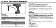
Gehäuse vorne 1<br />
@ Batteriefach mit Verschlussschraube<br />
Inhaltsverzeichnis<br />
= Dreifussverriegelung<br />
/ Kippachsmarkierung<br />
: Antrieb Horizontalkreis Klemmschraube und<br />
Feintrieb<br />
· Fussschraube des Dreifusses<br />
$ Dreifuss<br />
£ Laserlotgehäuse<br />
| Objektiv<br />
¡ Traggriff<br />
Gehäuse hinten 2<br />
; Fussschraube des Dreifusses<br />
% Bedienfeld mit Anzeige<br />
& Fokussierring<br />
( Okular<br />
) Röhrenlibelle<br />
+ Diopter<br />
§ Antrieb Vertikalkreis Klemmschraube und Feintrieb<br />
1 Allgemeine Hinweise .......................................................... 3<br />
1.1 Signalworte und Ihre Bedeutung ................................................. 3<br />
1.2 Erläuterung der Piktogramme und weitere Hinweise.................................. 3<br />
2 Beschreibung . . .............................................................. 3<br />
2.1 Gerätebeschreibung ........................................................... 3<br />
2.2 Lieferumfang der Standardausrüstung ............................................. 3<br />
3 Gerätebeschreibung .......................................................... 4<br />
3.1 Allgemeine Begriffe ........................................................... 4<br />
3.1.1 Bauachsen .................................................................. 4<br />
3.1.2 Fachspezifische Begriffe . ...................................................... 4<br />
3.2 Fernrohrlagen 34........................................................... 5<br />
3.3 Begriffe und deren Beschreibungen . . ............................................. 6<br />
3.4 Winkelmesssystem ............................................................ 6<br />
3.4.1 Messprinzip ................................................................. 6<br />
3.4.2 Einachskompensator .......................................................... 7<br />
3.5 Bedienfeld ................................................................... 8<br />
4 Werkzeuge, Zubehör ......................................................... <strong>10</strong><br />
5 Technische Daten ............................................................ <strong>10</strong><br />
1<br />
de
de<br />
6 Sicherheitshinweise ......................................................... 11<br />
6.1 Grundlegende Sicherheitsvermerke . . ............................................ 11<br />
6.2 Sachwidrige Anwendung. . . .................................................... 11<br />
6.3 Sachgemässe Einrichtung der Arbeitsplätze . . ..................................... 12<br />
6.4 Elektromagnetische Verträglichkeit . . ............................................ 12<br />
6.4.1 Laserklassifizierung .......................................................... 12<br />
6.5 Allgemeine Sicherheitsmassnahmen . ............................................ 12<br />
6.6 Transport ................................................................... 13<br />
7 Inbetriebnahme. ............................................................. 13<br />
7.1 Batterie laden ............................................................... 13<br />
7.2 Batterie einsetzen . ........................................................... 13<br />
7.3 Initialisierung Vertikalkreis .................................................... 14<br />
7.4 Funktionsüberprüfung ......................................................... 14<br />
7.5 Geräteaufstellung . ........................................................... 15<br />
7.5.1 Aufstellung über Bodenpunkt .................................................. 15<br />
7.5.2 Gerät aufstellen . ............................................................ 15<br />
7.5.3 Aufstellung auf Rohre mit Laserlot . ............................................. 16<br />
8 Bedienung .................................................................. 17<br />
8.1 Horizontalkreismessungen . .................................................... 17<br />
8.1.1 Horizontalkreisablesung Null setzen ............................................. 17<br />
8.1.2 Richtungsänderung Winkelmessung Horizontalkreis . . . .............................. 17<br />
8.1.3 Horizontalkreisanzeige setzen .................................................. 17<br />
8.2 Vertikalkreismessungen . . . .................................................... 18<br />
8.2.1 Vertikale Neigungsanzeige ..................................................... 18<br />
9 Einstellungen . . . ............................................................. 18<br />
9.1 Einstellungsmenü aufrufen . .................................................... 18<br />
9.2 Einstellung akustischer Winkelindikator pro Quadrant . . ............................. 19<br />
9.3 Winkeleinheiten . . ........................................................... 19<br />
9.4 Einstellung Zenit . . ........................................................... 19<br />
9.5 Ein- / Ausschalten automatische Abschaltung . ..................................... 20<br />
9.6 Einstellung Auflösung Anzeige Winkelmesssystem .................................. 20<br />
9.7 Ein-/Ausschalten Kompensator .................................................. 21<br />
9.8 Kalibrierung / Justierung für Vertikalkreis ......................................... 21<br />
9.8.1 Kalibriervorgang starten . ..................................................... 21<br />
<strong>10</strong> Kalibrieren und Justieren ..................................................... 22<br />
<strong>10</strong>.1 Hilti Kalibrierservice .......................................................... 22<br />
11 Pflege und Instandhaltung .................................................... 23<br />
11.1 Reinigen und trocknen ........................................................ 23<br />
11.2 Lagern . . ................................................................... 23<br />
11.3 Transportieren............................................................... 23<br />
12 Fehlersuche ................................................................. 24<br />
13 Entsorgung.................................................................. 24<br />
14 Herstellergewährleistung Geräte .............................................. 25<br />
2
15 FCC‑Hinweis (gültig in USA) / IC-Hinweis (gültig in Kanada) ..................... 25<br />
16 EG-Konformitätserklärung .................................................... 26<br />
1. Allgemeine Hinweise<br />
1.1 Signalworte und Ihre Bedeutung<br />
GEFAHR<br />
Für eine unmittelbar drohende Gefahr, die zu schweren<br />
Körperverletzungen oder zum Tod führt.<br />
WARNUNG<br />
Für eine möglicherweise gefährliche Situation, die zu<br />
schweren Körperverletzungen oder zum Tod führen<br />
kann.<br />
VORSICHT<br />
Für eine möglicherweise gefährliche Situation, die<br />
zu leichten Körperverletzungen oder zu Sachschaden<br />
führen könnte.<br />
HINWEIS<br />
Für Anwendungshinweise und andere nützliche Informationen.<br />
2. Beschreibung<br />
2.1 Gerätebeschreibung<br />
Der Hilti <strong>Theodolit</strong> <strong>POT</strong> <strong>10</strong> ist ausgelegt für horizontale<br />
und vertikale Winkelmessungen, für das Messen von<br />
90° Winkeln, für Messen von Neigungen in %, für das<br />
Fluchten von Bauachsen auf längere Distanzen (bis<br />
200 m) und für Bauachsübertragungen auf mehrere<br />
Stockwerke.<br />
Das Gerät besitzt einen Horizontal- und Vertikalkreis<br />
mit digitaler Kreiseinteilung und eine elektronische Li-<br />
1.2 Erläuterung der Piktogramme und weitere<br />
Hinweise<br />
Symbole<br />
Vor Benutzung<br />
Bedienungsanleitung<br />
lesen<br />
Warnung vor<br />
allgemeiner<br />
Gefahr<br />
Symbole Laserklasse II / class 2<br />
Laser Klasse 2<br />
gemäss<br />
EN 60825‑1:2003<br />
Laser Class II<br />
belle (1 Achs-Kompensator) für genaue Vertikalwinkel<br />
und Neigungsmessungen.<br />
2.2 Lieferumfang der Standardausrüstung<br />
1 <strong>Theodolit</strong><br />
1 Netzteil inkl. Ladekabel für Ladegerät<br />
1 Ladegerät<br />
1<br />
Batterie Typ Li-Ion 3.8 V 5200 mAh<br />
1 Justierset<br />
1 Bedienungsanleitung<br />
1 Hilti Koffer<br />
3<br />
de
de<br />
3. Gerätebeschreibung<br />
3.1 Allgemeine Begriffe<br />
3.1.1 Bauachsen<br />
Im Allgemeinen werden vor Baubeginn zuerst in und um das Baugebiet Höhenmarken und Bauachsen durch<br />
ein Vermessungsunternehmen markiert.<br />
Für jede Bauachse werden zwei Enden am Boden markiert.<br />
Von diesen Markierungen aus werden die einzelnen Bauelemente platziert. Bei grösseren Gebäuden ist eine<br />
Vielzahl von Bauachsen vorhanden.<br />
3.1.2 Fachspezifische Begriffe<br />
Geräteachsen<br />
4<br />
a Zielachse<br />
b Stehachse<br />
c Kippachse
Horizontalkreis / Horizontalwinkel<br />
Von den gemessenen horizontalen Kreisablesungen mit 70° zum einen Ziel und 40° zum anderen Ziel kann der<br />
eingeschlossene Winkel 70° - 40° = 30° berechnet werden.<br />
Vertikalkreis / Vertikalwinkel<br />
Dadurch, dass der Vertikalkreis mit 0° zur Gravitätsrichtung oder mit 0° zur Horizontalrichtung ausgerichtet<br />
werden kann, sind hier quasi Winkel von der Gravitätsrichtung bestimmt.<br />
3.2 Fernrohrlagen 34<br />
Damit sich die horizontalen Kreisablesungen richtig zum Vertikalwinkel zuordnen lassen, spricht man von<br />
Fernrohrlagen, d.h. je nach Richtung des Fernrohres zum Bedienfeld kann zugeordnet werden, in welcher<br />
"Lage" gemessen wurde.<br />
Wenn das Gerät in dieser Ansicht zu sehen ist, wird diese Lage als Fernrohrlage 1 bezeichnet. 3<br />
Wenn das Gerät in dieser Ansicht zu sehen ist, wird diese Lage als Fernrohrlage 2.bezeichnet. 4<br />
5<br />
de
de<br />
3.3 Begriffe und deren Beschreibungen<br />
Zielachse Linie durch Fadenkreuz und Objektivmitte (Fernrohrachse).<br />
Kippachse Drehachse des Fernrohrs.<br />
Stehachse Drehachse des gesamten Gerätes.<br />
Zenith Zenith ist die Richtung der Schwerkraft nach oben.<br />
Horizont Horizont ist die Richtung senkrecht zur Schwerkraft – allgemein<br />
horizontal bezeichnet.<br />
Nadir Nadir ist die Richtung der Schwerkraft nach unten.<br />
Vertikalkreis Als Vertikalkreis wird der Winkelkreis bezeichnet dessen Werte sich<br />
ändern, wenn das Fernrohr nach oben oder unten bewegt wird.<br />
Vertikalrichtung Als Vertikalrichtung wird eine Ablesung am Vertikalkreis bezeichnet.<br />
Vertikalwinkel Ein Vertikalwinkel besteht aus der Ablesung am Vertikalkreis.<br />
Der Vertikalkreis ist meistens mit Hilfe des Kompensators in Richtung<br />
der Schwerkraft ausgerichtet, mit der "Nullablesung" im Zenit.<br />
Höhenwinkel Höhenwinkel beziehen sich mit ’Null’ auf den Horizont und zählen<br />
positiv nach oben und negativ nach unten.<br />
Horizontalkreis Als Horizontalkreis wird der Winkelkreis bezeichnet dessen Werte<br />
sich ändern, wenn das Gerät gedreht wird.<br />
Horizontalrichtung Als Horizontalrichtung wird eine Ablesung am Horizontalkreis bezeichnet.<br />
Horizontalwinkel Ein Horizontalwinkel besteht aus der Differenz zweier Ablesungen<br />
am Horizontalkreis, aber oftmals wird eine Kreisablesung auch als<br />
Winkel bezeichnet.<br />
Alhidade Eine Alhidade ist der drehbare Mittelteil des <strong>Theodolit</strong>en.<br />
Dieser Teil trägt normalerweise das Bedienfeld, Libellen zum Horizontieren<br />
und im Innern den Horizontalkreis.<br />
Dreifuss Das Gerät steht im Dreifuss der z.B. auf einem Stativ befestigt ist.<br />
Der Dreifuss hat drei Auflagepunkte vertikal justierbar mit Stellschrauben.<br />
Gerätestation Die Stelle an der das Gerät aufgestellt ist - meistens über einem<br />
markierten Bodenpunkt.<br />
3.4 Winkelmesssystem<br />
Die Kreisablesungen für vertikal und horizontal erfolgt mit elektronischen Kreisablesungen.<br />
3.4.1 Messprinzip<br />
Das Gerät bestimmt eine Kreisablesung.<br />
Der eingeschlossene Winkel ergibt sich aus der Differenz zweier Kreisablesungen.<br />
6
3.4.2 Einachskompensator<br />
Mit Hilfe der elektronischen Libelle (Kompensator) wird die Geräteneigung in Fernrohrrichtung korrigiert.<br />
Damit wird sicher gestellt, dass Vertikalwinkel und Neigungen sich immer auf die Vertikale bzw. Horizontale<br />
beziehen.<br />
Der Einachskompensator misst mit hoher Genauigkeit die Geräteneigung in Richtung des Fernrohres, d.h. in<br />
Zielrichtung.<br />
Damit wird gewährleistet, dass der Einfluss der Restneigung keinen Einfluss auf die Vertikalwinkelmessung<br />
bzw. Neigung hat.<br />
7<br />
de
de<br />
3.5 Bedienfeld<br />
Das Bedienfeld besitzt insgesamt 6 mit Symbolen bedruckte Knöpfe und eine Anzeige.<br />
8
Gerät EIN / AUS.<br />
Hintergrundbeleuchtung Ein / Aus.<br />
Änderung der Richtung für die Winkelmessung des Horizontalkreises.<br />
Anhalten der aktuellen Horizontalkreisanzeige.<br />
Aktuellen Horizontalwinkel auf „0“ setzen.<br />
Wechseln der Vertikalkreisanzeige zwischen Grad und %.<br />
Batteriesymbol zur Anzeige des Ladezustands.<br />
Je voller das Batteriesymbol desto besser ist der Ladezustand.<br />
Wenn die Batterie nahezu komplett leer ist, verschwindet mit dem<br />
letzten Balken das ganze Batteriesymbol. Dann ist keine Energie für<br />
Messungen mehr vorhanden.<br />
V Aktuelle Vertikalkreisanzeige<br />
H Aktuelle Horizontalkreisanzeige.<br />
R oder L Anzeige aktuelle Messrichtung Horizontalkreis Rechts bzw. im Uhrzeigersinn<br />
oder Links bzw. im Gegenuhrzeigersinn.<br />
9<br />
de
de<br />
4. Werkzeuge, Zubehör<br />
Stromversorgung<br />
Stativ<br />
5. Technische Daten<br />
Technische Änderungen vorbehalten!<br />
Batterie POA 80<br />
Netzteil POA 81<br />
Ladegerät POA 82<br />
Stativ PUA 35<br />
Fernrohr<br />
Fernrohr Vergrösserung 30x<br />
Kürzeste Zielweite 1.5 m (4.9 ft)<br />
Fernrohrgesichtsfeld 1° 30': 2.6 m / <strong>10</strong>0 m (7.9 ft / 300 ft)<br />
Objektiv Öffnung<br />
Kompensator<br />
45 mm<br />
Typ 1 Achse, Flüssigkeit<br />
Arbeitsbereich ±3’<br />
Genauigkeit<br />
Winkelmessung<br />
5"<br />
<strong>POT</strong> <strong>10</strong> Genauigkeit (DIN 18723) 5"<br />
Winkelabgriffsystem V (incremental)<br />
Winkelabgriffsystem Hz (absolut)<br />
<strong>10</strong>
Laserlot<br />
Genauigkeit 1.5 mm auf 1.5 m (1/16 auf 3 ft)<br />
Leistung < 1 mW<br />
Laserklasse<br />
Anzeige<br />
Class 2<br />
Typ Segmentanzeige<br />
Beleuchtung<br />
Röhrenlibelle<br />
1-stufig<br />
Röhrenlibelle 30″ / 2mm<br />
IP Schutzklasse<br />
Klasse IP 55<br />
Stativgewinde<br />
Dreifussgewinde<br />
Batterie POA 80<br />
5/8''<br />
Typ Li-Ion<br />
Nennspannung 3,8 V<br />
Ladezeit 4 h<br />
Temperatur<br />
Betriebstemperatur -20…+50 °C (-4°F …+122°F)<br />
Lagertemperatur<br />
Masse und Gewichte<br />
-30…+70 °C (-22°F … +158°F)<br />
Abmessungen 164 mm x 154 mm x 340 mm<br />
Gewicht 4,6 kg<br />
Winkeleinheiten DMS, GON<br />
6. Sicherheitshinweise<br />
6.1 Grundlegende Sicherheitsvermerke<br />
Neben den sicherheitstechnischen Hinweisen in<br />
den einzelnen Kapiteln dieser Bedienungsanleitung<br />
sind folgende Bestimmungen jederzeit strikt zu beachten.<br />
6.2 Sachwidrige Anwendung<br />
Vom Gerät und seinen Hilfsmitteln können Gefahren<br />
ausgehen, wenn sie von unausgebildetem Personal<br />
unsachgemäss behandelt oder nicht bestimmungsgemäss<br />
verwendet werden.<br />
a) Verwenden Sie das Gerät nie ohne entsprechende<br />
Instruktionen erhalten zu haben oder<br />
diese Anleitung gelesen zu haben.<br />
b) Machen Sie keine Sicherheitseinrichtungen unwirksam<br />
und entfernen Sie keine Hinweis- und<br />
Warnschilder.<br />
11<br />
de
de<br />
c) Lassen Sie das Gerät nur durch Hilti-<br />
Servicestellen reparieren. Bei unsachgemässem<br />
Öffnen des Gerätes kann eine Laserstrahlung<br />
entstehen, die die Klasse 2 übersteigt.<br />
d) Manipulationen oder Veränderungen am Gerät<br />
sind nicht erlaubt.<br />
e) Benutzen Sie, um Verletzungsgefahren zu vermeiden,<br />
nur original Hilti Zubehör und Zusatzgeräte.<br />
f) Setzen Sie das Gerät nicht in explosionsgefährdeter<br />
Umgebung ein.<br />
g) Verwenden Sie zum Reinigen nur saubere und<br />
weiche Tücher. Falls nötig, können Sie diese mit<br />
reinem Alkohol etwas befeuchten.<br />
h) Halten Sie Kinder von Lasergeräten fern.<br />
i) Richten Sie das Gerät nicht gegen die Sonne oder<br />
andere starke Lichtquellen.<br />
j) Verwenden Sie das Gerät nicht als Nivellier.<br />
k) Überprüfen Sie das Gerät vor wichtigen Messungen,<br />
nach einem Sturz oder bei anderen mechanischen<br />
Einwirkungen.<br />
6.3 Sachgemässe Einrichtung der Arbeitsplätze<br />
a) Beachten Sie die landesspezifischen Unfallverhütungsvorschriften.<br />
b) Harte Stösse und starke Erschütterungen sind zu<br />
vermeiden<br />
c) Starke Temperaturschwankungen führen zum Beschlagen<br />
des Objektivs. Daher sollte das Gerät vor<br />
Gebrauch unbedingt akklimatisiert werden.<br />
d) Das Gerät sollte nicht für längere Zeit der prallen<br />
Sonne ausgesetzt werden.<br />
e) Entnehmen Sie die Batterie, wenn das Gerät längere<br />
Zeit nicht benutzt wird. Durch auslaufende<br />
Batterien/Akkus kann das Gerät beschädigt werden.<br />
f) Nach dem Gebrauch sollte das Geräte in trockenem<br />
Zustand im Koffer aufbewahrt werden.<br />
g) Die Libellen sollten in regelmässigen Abständen<br />
mit Umschlag geprüft und gegebenenfalls nachjustiert<br />
werden.<br />
6.4 Elektromagnetische Verträglichkeit<br />
Obwohl das Gerät die strengen Anforderungen der<br />
einschlägigen Richtlinien erfüllt, kann Hilti die Möglichkeit<br />
nicht ausschliessen, dass das Gerät<br />
- andere Geräte (z.B. Navigationseinrichtungen von<br />
Flugzeugen) stört oder<br />
- durch starke Strahlung gestört wird, was zu einer<br />
Fehloperation führen kann.<br />
12<br />
In diesen Fällen oder anderen Unsicherheiten sollten<br />
Kontrollmessungen durchgeführt werden.<br />
6.4.1 Laserklassifizierung<br />
Der Laserlot des Gerätes entspricht der Laserklasse<br />
2, basierend auf der Norm IEC825-1 / EN60825-<br />
01:2008 und der Klasse II basierend auf CFR 21 §<br />
<strong>10</strong>40 (FDA). Das Auge ist bei zufälligem, kurzzeitigem<br />
Hineinsehen in die Laserstrahlung durch den<br />
Lidschlussreflex geschützt. Dieser Lidschlussreflex<br />
kann jedoch durch Medikamente, Alkohol oder Drogen<br />
beeinträchtigt werden. Diese Geräte dürfen ohne<br />
weitere Schutzmassnahme eingesetzt werden. Trotzdem<br />
sollte man, wie auch bei der Sonne, nicht direkt<br />
in die Lichtquelle hineinsehen. Der Laserstrahl sollte<br />
nicht gegen Personen gerichtet werden.<br />
6.5 Allgemeine Sicherheitsmassnahmen<br />
a) Überprüfen Sie das Gerät vor dem Gebrauch<br />
auf eventuelle Beschädigungen. Falls das Gerät<br />
beschädigt ist, lassen Sie es durch eine Hilti-<br />
Servicestelle reparieren.<br />
b) Überprüfen Sie nach einem Sturz oder anderen<br />
mechanischen Einwirkungen die Genauigkeit<br />
des Geräts.<br />
c) Wenn das Gerät aus grosser Kälte in eine wärmere<br />
Umgebung gebracht wird oder umgekehrt,<br />
lassen Sie das Gerät vor dem Gebrauch akklimatisieren.<br />
d) Stellen Sie bei der Verwendung mit Stativen<br />
sicher, dass das Gerät fest aufgeschraubt ist<br />
und das Stativ sicher und fest am Boden steht.<br />
e) Halten Sie die Laseraustrittsfenster sauber, um<br />
Fehlmessungen zu vermeiden.<br />
f) Obwohl das Gerät für den harten Baustelleneinsatz<br />
konzipiert ist, sollten Sie es, wie andere<br />
optische und elektrische Geräte (Feldstecher,<br />
Brille, Fotoapparat) sorgfältig behandeln.<br />
g) Obwohl das Gerät gegen den Eintritt von Feuchtigkeit<br />
geschützt ist, sollten Sie das Gerät vor<br />
dem Verstauen in dem Transportbehälter trockenwischen.<br />
h) Prüfen Sie sicherheitshalber von Ihnen vorher<br />
eingestellte Werte bzw. vorherige Einstellungen.<br />
i) Beim Ausrichten des Gerätes mit der Dosenlibelle<br />
nur schräg auf das Gerät schauen.<br />
j) Verriegeln Sie die Batterietür sorgfältig, damit<br />
die Batterie nicht herausfallen kann oder
kein Kontakt entsteht, wodurch sich das Gerät<br />
unbeabsichtigt ausschalten kann und dies zu<br />
Datenverlust führen kann.<br />
7. Inbetriebnahme<br />
6.6 Transport<br />
Für den Versand des Geräts müssen Sie die Batterie<br />
isolieren oder aus dem Gerät entfernen. Durch auslaufende<br />
Batterien/Akkus kann das Gerät beschädigt<br />
werden.<br />
Um Umweltschäden zu vermeiden, müssen Sie das<br />
Gerät und die Batterie gemäss den jeweilig gültigen<br />
landesspezifischen Richtlinien entsorgen.<br />
Sprechen Sie im Zweifelsfall den Hersteller an.<br />
7.1 Batterie laden<br />
Nachdem Sie das Gerät ausgepackt haben, nehmen Sie zuerst das Netzgerät, Ladestation und Batterie aus dem<br />
Behälter.<br />
Laden Sie die Batterie für ca. 4 Stunden.<br />
7.2 Batterie einsetzen<br />
Batterie POA 80<br />
Netzteil POA 81<br />
Ladegerät POA 82<br />
Setzen Sie die geladene Batterie in das Gerät mit dem Batteriestecker zum Gerät hin und nach unten ein.<br />
Verriegeln Sie die Batterietür sorgfältig.<br />
13<br />
de
de<br />
7.3 Initialisierung Vertikalkreis<br />
Nach der Geräteaufstellung gemäss vorher beschriebenem Ablauf muss der Vertikalkreis des Gerätes initialisiert<br />
werden.<br />
Drehen Sie das Teleskop langsam um die Kippachse (c), bis eine Winkelanzeige für die Vertikalmessung<br />
erscheint.<br />
7.4 Funktionsüberprüfung<br />
HINWEIS<br />
Bitte beachten Sie, dass die Klemmschrauben gelöst werden, bevor das Gerät um die Alhidade gedreht wird.<br />
Die Seitentriebe für Horizontal und Vertikal arbeiten als Feintriebe die vorher geklemmt werden müssen.<br />
Überprüfen Sie zuerst die Gerätefunktionalität zu Beginn und in regelmässigen Abständen anhand folgender<br />
Kriterien:<br />
1. Lösen Sie die Klemmschrauben.<br />
2. Drehen Sie das Gerät mit der Hand vorsichtig nach links und rechts und das Fernrohr hoch und runter zur<br />
Kontrolle des Feinlaufes.<br />
3. Klemmen Sie Seitentrieb und Vertikaltrieb und drehen Sie die Seitentriebe für Horizontal und Vertikal<br />
vorsichtig in beide Richtungen.<br />
4. Drehen Sie den Fokussierring ganz nach links.<br />
5. Schauen Sie durch das Fernrohr und stellen Sie mit dem Okularring das Fadenkreuz scharf.<br />
6. Mit etwas Übung überprüfen Sie die Richtung der beiden Diopter auf dem Fernrohr mit der Übereinstimmung<br />
der Richtung des Fadenkreuzes.<br />
7. Überprüfen Sie den festen Sitz der Schrauben vom Handgriff.<br />
14
8. Siehe Kapitel: 7.3 Initialisierung Vertikalkreis<br />
7.5 Geräteaufstellung<br />
7.5.1 Aufstellung über Bodenpunkt<br />
Das Gerät besitzt ein Laserlot, das bei eingeschaltetem Gerät mit der Taste für die Hintergrundbeleuchtung einund<br />
ausgeschaltet wird.<br />
7.5.2 Gerät aufstellen<br />
1. Das Stativ mit Mitte Stativkopf grob über den Bodenpunkt aufstellen.<br />
2. Gerät auf das Stativ aufschrauben.<br />
3. Zwei Stativbeine mit der Hand so bewegen, dass sich der Laserstrahl auf der Bodenmarkierung befindet.<br />
HINWEIS Dabei ist zu beachten, dass der Stativkopf grob waagerecht steht.<br />
4. Danach die Stativbeine in den Boden treten.<br />
15<br />
de
de<br />
5. Restliche Abweichung vom Laserpunkt zur Bodenmarkierung mit den Fussschrauben wegstellen – der<br />
Laserpunkt muss sich jetzt exakt auf der Bodenmarkierung befinden.<br />
6. Durch Verlängerung der Stativbeine die Dosenlibelle am Dreifuss in die Mitte bewegen.<br />
HINWEIS Das geschieht indem man das der Blase gegenüberliegende Stativbein verlängert oder verkürzt,<br />
je nachdem in welche Richtung sich die Blase bewegen soll. Dies ist ein iterativer Prozess und muss<br />
eventuell mehrmals wiederholt werden.<br />
7. Nachdem die Blase der Dosenlibelle mittig steht, wird durch Verschieben des Gerätes auf dem Stativteller<br />
das Laserlot genau zentrisch auf den Bodenpunkt gesetzt.<br />
8. Danach die Röhrenlibelle parallel zu zwei Fussschrauben stellen und die Blase in die Mitte bringen<br />
9. Gerät um 90° drehen und mit Hilfe der dritten Fussschraube in die Mitte bringen – danach nochmals Gerät<br />
um 90° drehen und evtl. Röhrenlibelle mit den Fussschrauben nachjustieren.<br />
7.5.3 Aufstellung auf Rohre mit Laserlot<br />
Oftmals sind Bodenpunkte mit Rohren vermarkt.<br />
In diesem Fall zielt das Laserlot in das Rohr hinein, ohne Sichtkontakt.<br />
Legen Sie ein Papier, Folie oder anderes schwach durchsichtiges Material auf das Rohr,um den Laserpunkt<br />
sichtbar zu machen.<br />
16
8. Bedienung<br />
8.1 Horizontalkreismessungen<br />
8.1.1 Horizontalkreisablesung Null setzen<br />
Die Horizontalkreisablesung kann jederzeit durch Drücken der Taste 0- SET auf Null gesetzt werden und somit<br />
der Bezugs- oder Nullpunkt für den Horizontalkreis gesetzt werden.<br />
8.1.2 Richtungsänderung Winkelmessung Horizontalkreis<br />
Die Messrichtung für die horizontale Winkelmessung kann durch Drücken der Taste R/L zwischen Rechts –<br />
im Uhrzeigersinn und Links – im Gegenuhrzeigersinn geändert werden.<br />
In der Anzeige wird dies durch das R für Rechts oder L für Links unterhalb des H angezeigt.<br />
Beim Einschalten des Gerätes wird die Messrichtung Rechts bzw. im Uhrzeigersinn als Standard gesetzt.<br />
8.1.3 Horizontalkreisanzeige setzen<br />
Die Horizontalkreisablesung kann durch Drücken der Taste HOLD festgehalten werden, dann das neue Ziel<br />
anvisiert und durch erneutes Drücken die Kreisablesung wieder gelöst werden.<br />
HINWEIS<br />
Während die Kreisablesung festgehalten ist, blinken in der Anzeige die Buchstaben H sowie RL darunter.<br />
17<br />
de
de<br />
8.2 Vertikalkreismessungen<br />
8.2.1 Vertikale Neigungsanzeige<br />
Die Vertikalkreisablesung lässt sich zwischen Grad- und Prozent(%)-Anzeige umstellen.<br />
HINWEIS<br />
Die %-Anzeige ist nur für diese Anzeige aktiv.<br />
Damit lassen sich Neigungen in % messen bzw. ausrichten.<br />
Die Messungen von Neigungen in % funktioniert nur im Bereich von ± <strong>10</strong>0%, das sind ± 45°.<br />
Darüber bzw. darunter ist keine Messung möglich und daher verschwindet dann auch die Anzeige.<br />
Zum Wechseln der Vertikalkreisanzeige zwischen Grad und % ist die Taste V% zu drücken.<br />
9. Einstellungen<br />
9.1 Einstellungsmenü aufrufen<br />
Um in das Einstellungsmenü zu gelangen muss das Gerät ausgeschalten sein.<br />
Drücken Sie die Taste Hold und die Taste 0-Set gleichzeitig und halten Sie diese gedrückt.<br />
Drücken Sie zusätzlich die Einschalttaste und lassen Sie diese erst los bis auf der Anzeige alle Segmente zu<br />
sehen sind.<br />
Lassen Sie die beiden Tasten Hold und 0-Set los nachdem vier Pieptöne zu hören waren.<br />
Das Gerät befindet sich danach im Modus um Einstellungen vornehmen zu können.<br />
Drücken Sie die Taste Hold um zwischen den verschiedenen Einstellungen zu wechseln<br />
Drücken Sie die Taste 0-Set um zwischen den einzelnen Parameter einer Einstellung zu wechseln<br />
Drücken Sie die Taste V% um die vorgenommenen Einstellungen zu bestätigen und speichern sowie den<br />
Einstellmodus zu verlassen.<br />
Das Gerät befindet sich danach im normalen Betriebsmodus um Messungen durchzuführen.<br />
18
9.2 Einstellung akustischer Winkelindikator pro Quadrant<br />
Akustischer Indikator pro Quadrant bzw. alle 90°/<strong>10</strong>0Gon<br />
Indikator EIN<br />
Anzeige 90 bEEP<br />
AUS<br />
Anzeige NO bEEP<br />
9.3 Winkeleinheiten<br />
Änderung der Winkeleinheiten für die Kreisablesungen<br />
Grad (dms) Anzeige 360° ´ “<br />
Gon Anzeige 400 G<br />
9.4 Einstellung Zenit<br />
Einstellung des Zenits bzw. der Bezugsposition für Vertikalkreisablesungen<br />
19<br />
de
de<br />
Zenith bei 0° (oben)<br />
Anzeige ZEN==0<br />
bei 90° (hinten)<br />
Anzeige ZEN==90<br />
9.5 Ein- / Ausschalten automatische Abschaltung<br />
Ein- bzw. Ausschalten der automatischen Abschaltung des Gerätes<br />
Mögliche Einstellungen Aus<br />
Anzeige NO OFF<br />
Automatische Abschaltung nach 30min<br />
Anzeige 30 OFF<br />
9.6 Einstellung Auflösung Anzeige Winkelmesssystem<br />
Einstellen der Anzeigegenauigkeit<br />
20<br />
Mögliche Einstellungen 1″<br />
Anzeige dSP 1<br />
5″<br />
Anzeige dSP 5<br />
<strong>10</strong>″<br />
Anzeige dSP <strong>10</strong>
9.7 Ein-/Ausschalten Kompensator<br />
Ein- bzw. Ausschalten des Kompensators<br />
Mögliche Einstellungen Ein<br />
Anzeige TILT ON<br />
Aus<br />
Anzeige TILT OFF<br />
9.8 Kalibrierung / Justierung für Vertikalkreis<br />
Das Gerät ist bei Auslieferung richtig eingestellt.<br />
Auf Grund von Temperaturschwankungen, Transportbewegungen und Alterung besteht die Möglichkeit, dass<br />
sich die Einstellwerte des Gerätes über die Zeit verändern.<br />
Daher bietet das Gerät die Möglichkeit mit einer Funktion die Einstellwerte zu überprüfen und gegebenenfalls<br />
mit einer Feldkalibrierung zu korrigieren.<br />
Hierzu wird das Gerät mit einem qualitativ guten Stativ sicher aufgestellt und ein gut sichtbares, genau<br />
erkennbares Ziel innerhalb von ±3 Grad zur Horizontalen in ca. 70 – 120 m Entfernung verwendet.<br />
9.8.1 Kalibriervorgang starten<br />
1. Halten Sie die R/L-Taste und die Hold-Taste gedrückt und drücken Sie dann die EIN/AUS-Taste.<br />
2. Warten Sie bis alle Anzeigecharakter erscheinen und lassen Sie zuerst die Tasten R/L und Hold los.<br />
21<br />
de
de<br />
3. Zielen Sie das ausgewählte Ziel genau an.<br />
4. Warten Sie bis sich die Anzeige vom V – Winkel nicht mehr bewegt.<br />
5. Danach drücken Sie die Taste 0SET um die Winkelmessung in Lage 1 durchzuführen.<br />
Gleichzeitig springt die Anzeige zur Messungsaufforderung in Lage 2.<br />
6. Wechseln Sie jetzt in die Lage 2 und zielen Sie das gewählte Ziel in Lage 2 an.<br />
7. Drücken Sie die Taste 0SET um eine Winkelmessung in Lage 2 auszuführen.<br />
Nach der zweiten Messung wird die Korrektur für den Vertikalkreis berechnet und intern gespeichert und<br />
die aktuellen Winkel angezeigt.<br />
8. Zur Sicherheit messen Sie zum Ziel nochmals in beiden Lagen.<br />
HINWEIS Der Vertikalkreis ist richtig korrigiert, wenn die Summe beider V – Winkel (Lage 1 + Lage 2)<br />
gleich 360° ergibt.<br />
<strong>10</strong>. Kalibrieren und Justieren<br />
<strong>10</strong>.1 Hilti Kalibrierservice<br />
Wir empfehlen die regelmässige Überprüfung der Geräte durch den Hilti Kalibrierservice zu nutzen, um die<br />
Zuverlässigkeit gemäss Normen und rechtlichen Anforderungen gewährleisten zu können.<br />
Der Hilti Kalibrierservice steht Ihnen jederzeit zur Verfügung; empfiehlt sich aber mindestens einmal jährlich<br />
durchzuführen.<br />
22
Im Rahmen des Hilti Kalibrierservice wird bestätigt, dass die Spezifikationen des geprüften Geräts am Tag der<br />
Prüfung den technischen Angaben der Bedienungsanleitung entsprechen.<br />
Bei Abweichungen von den Herstellerangaben werden die gebrauchten Messgeräte wieder neu eingestellt.<br />
Nach der Justierung und Prüfung wird eine Kalibrierplakette am Gerät angebracht und mit einem Kalibrierzertifikat<br />
schriftlich bestätigt, dass das Gerät innerhalb der Herstellerangaben arbeitet.<br />
Kalibrierzertifikate werden immer benötigt für Unternehmen, die nach ISO 900X zertifiziert sind. Ihr nächstliegender<br />
Hilti Kontakt gibt Ihnen gerne weitere Auskunft.<br />
11. Pflege und Instandhaltung<br />
HINWEIS<br />
Lassen Sie beschädigte Teile vom Hilti Service auswechseln.<br />
11.1 Reinigen und trocknen<br />
Blasen Sie den Staub vom Glas.<br />
VORSICHT<br />
Berühren Sie das Glas nicht mit Ihren Fingern.<br />
Reinigen Sie das Gerät nur mit einem sauberen,<br />
weichen Lappen. Befeuchten Sie es, wenn nötig, mit<br />
reinem Alkohol oder Wasser.<br />
VORSICHT<br />
Verwenden Sie keine anderen Flüssigkeiten ausser Alkohol<br />
oder Wasser. Diese könnten die Kunststoffteile<br />
angreifen.<br />
HINWEIS<br />
Lassen Sie beschädigte Teile auswechseln<br />
11.2 Lagern<br />
HINWEIS<br />
Lagern Sie das Gerät nicht in nassem Zustand. Lassen<br />
Sie es trocknen bevor Sie es verstauen und lagern.<br />
HINWEIS<br />
Reinigen Sie vor dem Lagern immer das Gerät, den<br />
Transportbehälter und das Zubehör.<br />
HINWEIS<br />
Führen Sie nach längerer Lagerung oder längerem<br />
Transport Ihrer Ausrüstung vor Gebrauch eine Kontrollmessung<br />
durch.<br />
VORSICHT<br />
Entnehmen Sie die Batterie, wenn das Gerät längere<br />
Zeit nicht benutzt wird. Durch auslaufende Batterien/Akkus<br />
kann das Gerät beschädigt werden.<br />
HINWEIS<br />
Beachten Sie die Temperaturgrenzwerte bei der Lagerung<br />
Ihrer Ausrüstung, speziell im Winter oder<br />
Sommer, insbesondere wenn Sie Ihre Ausrüstung im<br />
Fahrzeug-Innenraum aufbewahren. (-30°C bis +70°C<br />
(-22°F bis +158°F)).<br />
11.3 Transportieren<br />
VORSICHT<br />
Für den Versand des Geräts müssen Sie die Batterie<br />
isolieren oder aus dem Gerät entfernen. Durch auslaufende<br />
Batterien/Akkus kann das Gerät beschädigt<br />
werden.<br />
Verwenden Sie für den Transport oder Versand Ihrer<br />
Ausrüstung entweder den Hilti-Versandkarton oder<br />
eine gleichwertige Verpackung.<br />
23<br />
de
de<br />
12. Fehlersuche<br />
Fehler Mögliche Ursache Behebung<br />
Das Gerät lässt sich nicht<br />
einschalten.<br />
Keine Stromversorgung Batterie nach Vorgabe laden.<br />
E01 Zählfehler, wenn bei der Peilung<br />
sich die Messwertanzeige ständig<br />
ändert.<br />
Reparatur erforderlich.<br />
TOO FAST Das Teleskop wird zu schnell für<br />
den Vertikalsensor gedreht.<br />
Langsamer drehen.<br />
HINWEIS<br />
Lassen sich die Fehler mit den aufgeführten Abhilfemassnahmen nicht beheben, muss das Gerät in ein Hilti<br />
Service Center gesandt werden.<br />
13. Entsorgung<br />
WARNUNG<br />
Bei unsachgemässem Entsorgen der Ausrüstung können folgende Ereignisse eintreten:<br />
Beim Verbrennen von Kunststoffteilen entstehen giftige Abgase, an denen Personen erkranken können.<br />
Batterien können explodieren und dabei Vergiftungen, Verbrennungen, Verätzungen oder Umweltverschmutzung<br />
verursachen, wenn sie beschädigt oder stark erwärmt werden.<br />
Bei leichtfertigem Entsorgen ermöglichen Sie unberechtigten Personen, die Ausrüstung sachwidrig zu verwenden.<br />
Dabei können Sie sich und Dritte schwer verletzen sowie die Umwelt verschmutzen.<br />
Falls Sie das Gerät selbst einer Stofftrennung zuführen wollen: Zerlegen Sie das Gerät, soweit dies ohne<br />
Spezialwerkzeug möglich ist.<br />
Hilti-Geräte sind zu einem hohen Anteil aus wiederverwertbaren Materialien hergestellt. Voraussetzung für<br />
eine Wiederverwertung ist eine sachgemässe Stofftrennung. In vielen Ländern ist Hilti bereits eingerichtet, Ihr<br />
Altgerät zur Verwertung zurückzunehmen. Fragen Sie den Hilti Kundenservice oder Ihren Verkaufsberater.<br />
Trennen Sie die Einzelteile wie folgt:<br />
Bauteil/ Baugruppe Hauptwerkstoff Verwertung<br />
Gehäuse Kunststoff Kunststoffrecycling, Altmetall<br />
Schalter Kunststoff Kunststoffrecycling<br />
Schrauben, Kleinteile Stahl, Aluminium, Magnete Altmetall<br />
Elektronik Verschiedene Elektronikschrott<br />
Batterien / Akkus Alkalimangan Nationale Vorschriften<br />
Gerätetasche Gewobenes Synthetik-Material Kunststoffrecycling<br />
24
Nur für EU Länder<br />
Werfen Sie elektronische Messgeräte nicht in den Hausmüll!<br />
Gemäss Europäischer Richtlinie 2002/96/EG und 2006/66/EG über Elektro- und Elektronik-<br />
Altgeräte und Umsetzung in nationales Recht müssen verbrauchte Elektrowerkzeuge und<br />
Akku‑Packs getrennt gesammelt und einer umweltgerechten Wiederverwertung zugeführt werden.<br />
Entsorgen Sie die Batterien nach den nationalen Vorschriften. Bitte helfen Sie die Umwelt zu<br />
schützen.<br />
14. Herstellergewährleistung Geräte<br />
Hilti gewährleistet, dass das gelieferte Gerät frei von<br />
Material- und Fertigungsfehler ist. Diese Gewährleistung<br />
gilt unter der Voraussetzung, dass das Gerät in<br />
Übereinstimmung mit der Hilti Bedienungsanleitung<br />
richtig eingesetzt und gehandhabt, gepflegt und gereinigt<br />
wird, und dass die technische Einheit gewahrt<br />
wird, d.h. dass nur Original Hilti Verbrauchsmaterial,<br />
Zubehör und Ersatzteile mit dem Gerät verwendet<br />
werden.<br />
Diese Gewährleistung umfasst die kostenlose Reparatur<br />
oder den kostenlosen Ersatz der defekten<br />
Teile während der gesamten Lebensdauer des Gerätes.<br />
Teile, die dem normalen Verschleiss unterliegen,<br />
fallen nicht unter diese Gewährleistung.<br />
Weitergehende Ansprüche sind ausgeschlossen,<br />
soweit nicht zwingende nationale Vorschriften ent-<br />
gegenstehen. Insbesondere haftet Hilti nicht für<br />
unmittelbare oder mittelbare Mangel- oder Mangelfolgeschäden,<br />
Verluste oder Kosten im Zusammenhang<br />
mit der Verwendung oder wegen der Unmöglichkeit<br />
der Verwendung des Gerätes für irgendeinen<br />
Zweck. Stillschweigende Zusicherungen<br />
für Verwendung oder Eignung für einen bestimmten<br />
Zweck werden ausdrücklich ausgeschlossen.<br />
Für Reparatur oder Ersatz sind Gerät oder betroffene<br />
Teile unverzüglich nach Feststellung des Mangels an<br />
die zuständige Hilti Marktorganisation zu senden.<br />
Die vorliegende Gewährleistung umfasst sämtliche<br />
Gewährleistungsverpflichtungen seitens Hilti und ersetzt<br />
alle früheren oder gleichzeitigen Erklärungen,<br />
schriftlichen oder mündlichen Verabredungen betreffend<br />
Gewährleistung.<br />
15. FCC‑Hinweis (gültig in USA) / IC-Hinweis (gültig in Kanada)<br />
VORSICHT<br />
Dieses Gerät hat in Tests die Grenzwerte eingehalten,<br />
die in Abschnitt 15 der FCC-Bestimmungen für<br />
digitale Geräte der Klasse B festgeschrieben sind.<br />
Diese Grenzwerte sehen für die Installation in Wohngebieten<br />
einen ausreichenden Schutz vor störenden<br />
Abstrahlungen vor. Geräte dieser Art erzeugen und<br />
verwenden Hochfrequenzen und können diese auch<br />
ausstrahlen. Sie können daher, wenn sie nicht den<br />
Anweisungen entsprechend installiert und betrieben<br />
werden, Störungen des Rundfunkempfangs verursachen.<br />
Es kann aber nicht garantiert werden, dass bei bestimmten<br />
Installationen nicht doch Störungen auftreten<br />
können. Falls dieses Gerät Störungen des Radio-<br />
oder Fernsehempfangs verursacht, was durch Ausund<br />
Wiedereinschalten des Geräts festgestellt werden<br />
kann, ist der Benutzer angehalten, die Störungen mit<br />
Hilfe folgender Massnahmen zu beheben:<br />
Die Empfangsantenne neu ausrichten oder versetzen.<br />
Den Abstand zwischen Gerät und Empfänger vergrössern.<br />
Lassen Sie sich von Ihrem Händler oder einem erfahrenen<br />
Radio- und Fernsehtechniker helfen.<br />
HINWEIS<br />
Änderungen oder Modifikationen, die nicht ausdrücklich<br />
von Hilti erlaubt wurden, kann das Recht des<br />
25<br />
de
de<br />
Anwenders einschränken, das Gerät in Betrieb zu<br />
nehmen.<br />
16. EG-Konformitätserklärung<br />
Bezeichnung: <strong>Theodolit</strong><br />
Typenbezeichnung: <strong>POT</strong> <strong>10</strong><br />
Konstruktionsjahr: 20<strong>10</strong><br />
Wir erklären in alleiniger Verantwortung, dass dieses<br />
Produkt mit den folgenden Richtlinien und Normen<br />
übereinstimmt: EN 6<strong>10</strong>00‑6‑1, EN 6<strong>10</strong>00‑6‑3,<br />
2006/95/EG, 2004/<strong>10</strong>8/EG.<br />
Index<br />
A<br />
Automatische Abschaltung<br />
ein- ausschalten . . . . . . . . . . . . . . . . 2, 20<br />
B<br />
Batterie<br />
einsetzen . . . . . . . . . . . . . . . . . . . . 2, 13<br />
Batterie POA 80 . . . . . . . . . . . . . . . 3, <strong>10</strong>, 13<br />
Bauachsen . . . . . . . . . . . . . . . . . . . . . 1, 4<br />
Bedienfeld . . . . . . . . . . . . . . . . . . . . . 1, 8<br />
E<br />
E01 .......................... 24<br />
Einachskompensator . . . . . . . . . . . . . . . 1, 7<br />
Einstellungsmenü . . . . . . . . . . . . . . . . 2, 18<br />
F<br />
Fernrohrlagen . . . . . . . . . . . . . . . . . . . 1, 5<br />
Funktionsüberprüfung . . . . . . . . . . . . . 2, 14<br />
G<br />
Gerät<br />
aufstellen . . . . . . . . . . . . . . . . . . . . 2, 15<br />
Gerät aufstellen<br />
auf Rohre mit Laserlot . . . . . . . . . . . . 2, 16<br />
Geräteaufstellung . . . . . . . . . . . . . . . . 2, 15<br />
26<br />
Hilti Aktiengesellschaft<br />
Dietmar Sartor Tassilo Deinzer<br />
Head of BA Quality and Process Management<br />
Head BU Measuring Systems<br />
Business Area Electric Tools & Accessories<br />
BU Measuring Systems<br />
08 20<strong>10</strong> 08 20<strong>10</strong><br />
H<br />
Horizontalkreis<br />
Winkelmessung . . . . . . . . . . . . . . . . 2, 17<br />
Horizontalkreisablesung . . . . . . . . . . . . 2, 17<br />
Horizontalkreisanzeige . . . . . . . . . . . . . 2, 17<br />
J<br />
Justierset . . . . . . . . . . . . . . . . . . . . . . . . 3<br />
Justierung<br />
Kalibrierung . . . . . . . . . . . . . . . . . . 2, 21<br />
K<br />
Kalibrieren . . . . . . . . . . . . . . . . . . . . 2, 21<br />
Kalibrierservice<br />
Kalibrierung<br />
. . . . . . . . . . . . . . . . . 2, 22<br />
Justierung . . . . . . . . . . . . . . . . . . .<br />
Kompensator<br />
2, 21<br />
ein- ausschalten . . . . . . . . . . . . . . . . 2, 21<br />
L<br />
Ladegerät POA 82 . . . . . . . . . . . . . . 3, <strong>10</strong>, 13<br />
M<br />
Messprinzip . . . . . . . . . . . . . . . . . . . . 1, 6
N<br />
Neigungsanzeige<br />
vertikal . . . . . . . . . . . . . . . . . . . . . 2, 18<br />
Netzteil POA 81 . . . . . . . . . . . . . . . 3, <strong>10</strong>, 13<br />
S<br />
Stativ PUA 35 . . . . . . . . . . . . . . . . . . . . <strong>10</strong><br />
T<br />
TOO FAST . . . . . . . . . . . . . . . . . . . . . . 24<br />
W<br />
Winkeleinheiten . . . . . . . . . . . . . . . . . 2, 19<br />
Winkelindikator . . . . . . . . . . . . . . . . . 2, 19<br />
Winkelmesssystem . . . . . . . . . . . . . 1-2, 6, 20<br />
Winkelmessung<br />
Horizontalkreis . . . . . . . . . . . . . . . . 2, 17<br />
Z<br />
Zenith . . . . . . . . . . . . . . . . . . . . . . . 2, 19<br />
27<br />
de
de<br />
28
ORIGINAL OPERATING INSTRUCTIONS<br />
<strong>POT</strong> <strong>10</strong> theodolite<br />
It is essential that the operating instructions<br />
are read before the tool is operated<br />
for the first time.<br />
Always keep these operating instructions<br />
together with the tool.<br />
Ensure that the operating instructions are<br />
with the tool when it is given to other persons.<br />
1These numbers refer to the corresponding illustrations.<br />
The illustrations can be found on the fold-out<br />
cover pages. Keep these pages open while studying<br />
the operating instructions.<br />
In these operating instructions, the designation “the<br />
tool” always refers to the <strong>POT</strong> <strong>10</strong> theodolite.<br />
Contents<br />
Housing, front 1<br />
@ Battery compartment with securing screw<br />
= Tribrach lock<br />
/ Trunnion (tilt axis) scale<br />
: Horizontal circle drive locking knob and fine<br />
adjustment<br />
· Tribrach footscrew<br />
$ Tribrach<br />
£ Laser plummet housing<br />
| Objective lens<br />
¡ Carrying handle<br />
Housing, rear 2<br />
; Tribrach footscrew<br />
% Control panel with display<br />
& Focusing ring<br />
( Eyepiece<br />
) Tubular level<br />
+ Sight<br />
§ Vertical circle drive locking knob and fine adjustment<br />
1 General information .......................................................... 31<br />
1.1 Safety notices and their meaning ................................................ 31<br />
1.2 Explanation of the pictograms and other information . . . ............................. 31<br />
2 Description.................................................................. 31<br />
2.1 Description of the tool......................................................... 31<br />
2.2 Items supplied with the standard version.......................................... 31<br />
3 Description of the tool . . . ..................................................... 32<br />
3.1 General terms ............................................................... 32<br />
3.1.1 Control lines . . . ............................................................ 32<br />
3.1.2 Technical terms . ............................................................ 32<br />
3.2 Telescope positions 34 ..................................................... 33<br />
3.3 Terms and their description .................................................... 34<br />
3.4 Angle measurement system .................................................... 34<br />
3.4.1 Measuring principle .......................................................... 34<br />
3.4.2 Single-axis compensator . ..................................................... 35<br />
3.5 Control panel ................................................................ 36<br />
4 Insert tools, accessories. ..................................................... 37<br />
29<br />
en
en<br />
5 Technical data. . ............................................................. 37<br />
6 Safety instructions ........................................................... 38<br />
6.1 Basic information concerning safety . ............................................ 38<br />
6.2 Misuse . . ................................................................... 38<br />
6.3 Proper organization of the work area . ............................................ 39<br />
6.4 Electromagnetic compatibility .................................................. 39<br />
6.4.1 Laser classification .......................................................... 39<br />
6.5 General safety rules .......................................................... 39<br />
6.6 Transport ................................................................... 39<br />
7 Before use .................................................................. 40<br />
7.1 Charging the battery .......................................................... 40<br />
7.2 Inserting the battery .......................................................... 40<br />
7.3 Initializing the vertical circle ................................................... 40<br />
7.4 Checking functions ........................................................... 41<br />
7.5 Setting up the tool . ........................................................... 42<br />
7.5.1 Setting up over a point on the ground ............................................ 42<br />
7.5.2 Setting up the tool ........................................................... 42<br />
7.5.3 Setting up over a pipe using the laser plummet ..................................... 43<br />
8 Operation ................................................................... 43<br />
8.1 Measuring using the horizontal circle ............................................ 43<br />
8.1.1 Zeroing before reading from the horizontal circle ................................... 43<br />
8.1.2 Changing the direction of angle measurement with the horizontal circle . . . ............... 44<br />
8.1.3 Setting the horizontal circle display . ............................................. 44<br />
8.2 Measuring using the vertical circle . . ............................................ 44<br />
8.2.1 Indication of inclination . . ..................................................... 44<br />
9 Settings. .................................................................... 45<br />
9.1 Displaying the settings menu ................................................... 45<br />
9.2 Setting the audible angle indicator for each quadrant . . . ............................. 45<br />
9.3 Angle units ................................................................. 46<br />
9.4 Setting the zenith . ........................................................... 46<br />
9.5 Activating / deactivating automatic power-off . ..................................... 46<br />
9.6 Setting display resolution for the angle measurement system . . . ...................... 47<br />
9.7 Switching the compensator on / off . . ............................................ 47<br />
9.8 Calibration / adjustment of the vertical circle . ..................................... 47<br />
9.8.1 Starting the calibration procedure . . ............................................. 48<br />
<strong>10</strong> Calibration and adjustment ................................................... 49<br />
<strong>10</strong>.1 Hilti Calibration Service . . . .................................................... 49<br />
11 Care and maintenance . . ..................................................... 49<br />
11.1 Cleaning and drying .......................................................... 49<br />
11.2 Storage . ................................................................... 49<br />
11.3 Transport ................................................................... 50<br />
12 Troubleshooting ............................................................. 50<br />
13 Disposal .................................................................... 50<br />
30
14 Manufacturer’s warranty ..................................................... 51<br />
15 FCC statement (applicable in US) / IC statement (applicable in Canada) . . . ........ 52<br />
16 EC declaration of conformity .................................................. 52<br />
1. General information<br />
1.1 Safety notices and their meaning<br />
DANGER<br />
Draws attention to imminent danger that could lead<br />
to serious bodily injury or fatality.<br />
WARNING<br />
Draws attention to a potentially dangerous situation<br />
that could lead to serious personal injury or fatality.<br />
CAUTION<br />
Draws attention to a potentially dangerous situation<br />
that could lead to slight personal injury or damage to<br />
the equipment or other property.<br />
NOTE<br />
Draws attention to an instruction or other useful<br />
information.<br />
2. Description<br />
2.1 Description of the tool<br />
The Hilti <strong>POT</strong> <strong>10</strong> theodolite is designed for measuring<br />
horizontal and vertical angles, 90° angles, inclinations<br />
in %, the alignment of control lines over great<br />
distances (up to 200 m) and for transferring control<br />
lines over several building floor levels.<br />
The tool is equipped with horizontal and vertical<br />
circles with digital graduation and an electronic level<br />
(single-axis compensator) for precise measurement<br />
of vertical angles and inclinations.<br />
1.2 Explanation of the pictograms and other<br />
information<br />
Symbols<br />
Read the<br />
operating<br />
instructions<br />
before use.<br />
General<br />
warning<br />
Symbol for Laser Class II / Class 2<br />
Laser class 2<br />
in accordance<br />
with<br />
EN 60825-<br />
1:2003<br />
Laser Class II<br />
2.2 Items supplied with the standard version<br />
1 <strong>Theodolit</strong>e<br />
1 AC adapter incl. charging cable for chargers<br />
1 Charger<br />
1<br />
3.8 V 5200 mAh Li-ion battery<br />
1 Adjusting set<br />
1 Operating instructions<br />
1 Hilti toolbox<br />
31<br />
en
en<br />
3. Description of the tool<br />
3.1 General terms<br />
3.1.1 Control lines<br />
Height marks and control lines are generally marked out on and around the building plot by a surveyor before<br />
construction begins.<br />
Two ends are marked on the ground for each control line.<br />
These marks are used to position the individual components of the building or structure. Large buildings<br />
require a number of control lines.<br />
3.1.2 Technical terms<br />
Tool axes<br />
32<br />
a Target axis<br />
b Vertical axis<br />
c Trunnion (tilt axis)
Horizontal circle / horizontal angle<br />
The included angle of 70°- 40° = 30° can be calculated from the horizontal circle readings of 70° to one target<br />
and 40° to the other target.<br />
Vertical circle / vertical angle<br />
As the vertical circle can be aligned at 0° to the direction of gravity or at 0° to horizontal, angles can be<br />
determined relative to the direction of gravity, so to speak.<br />
3.2 Telescope positions 34<br />
The term “telescope position” is used to ensure that readings from the horizontal circle can be correctly<br />
assigned to the vertical angle, i.e. the position of the telescope relative to the control panel determines in which<br />
“position” the measurements have been taken.<br />
When the tool appears as shown in this view, this is described as “telescope position 1”. 3<br />
When the tool appears as shown in this view, this is described as “telescope position 2”. 4<br />
33<br />
en
en<br />
3.3 Terms and their description<br />
Target axis A line through the cross hairs and center of the objective lens (telescope<br />
axis).<br />
Trunnion The telescope pivot (tilt) axis.<br />
Vertical axis The pivot axis of the entire tool.<br />
Zenith The zenith is the point that lies in the direction of gravity, but in the<br />
opposite, upward direction.<br />
Horizon The horizon is the direction perpendicular to the direction of gravity<br />
– generally known as horizontal.<br />
Nadir Nadir is the name given to the downward direction in which gravity<br />
acts.<br />
Vertical circle The vertical circle is the circle of angles described by the telescope<br />
when it is tilted upwards or downwards.<br />
Vertical direction A reading taken from the vertical circle is known as the vertical direction.<br />
Vertical angle A vertical angle is a reading from the vertical circle.<br />
The vertical circle is usually aligned with the direction of gravity with<br />
the aid of the compensator, with the zero point at the zenith.<br />
Elevation angle An elevation angle of zero refers to the horizon (horizontal plane).<br />
Positive angles are above horizontal (upwards) and negative angles<br />
are below horizontal (downwards).<br />
Horizontal circle The horizontal circle is the complete circle of angles described by<br />
the tool when it is rotated.<br />
Horizontal direction A reading taken from the horizontal circle is known as the horizontal<br />
direction.<br />
Horizontal angle A horizontal angle is the difference between two readings from the<br />
horizontal circle. However, a reading from one of the circles is also<br />
often described as an angle.<br />
Alidade The rotatable center part of the theodolite is known as the alidade.<br />
This part usually carries the control panel, bubble levels for leveling<br />
and, inside, the horizontal circle.<br />
Tribrach The tool stands on the tribrach which, for example, can be mounted<br />
on a tripod.<br />
The tribrach has three points of contact which can be adjusted vertically<br />
by adjusting screws.<br />
Tool standpoint This is the point at which the tool is set up - usually over a point<br />
marked on the ground.<br />
3.4 Angle measurement system<br />
An electronic reading system is used for vertical and horizontal circle readings.<br />
3.4.1 Measuring principle<br />
The tool provides a reading from one of the circles.<br />
The included angle is the difference between two readings from a circle.<br />
34
3.4.2 Single-axis compensator<br />
Tool tilt in the direction of the telescope is corrected with the aid of the electronic level (compensator).<br />
This ensures that vertical angle and inclination are always relative to the vertical or horizontal plane.<br />
The single-axis compensator measures tool tilt in the direction of the telescope, i.e. in the target direction.<br />
This ensures that residual inclination has no influence on vertical angle measurement.<br />
35<br />
en
en<br />
3.5 Control panel<br />
The control panel features a display and a total of 6 buttons each marked with a symbol.<br />
Tool ON / OFF.<br />
Back light on / off.<br />
Change the direction for horizontal circle angle measurement.<br />
Hold the horizontal circle reading currently displayed.<br />
Set the current horizontal angle to “0”.<br />
Switch between degrees and % when displaying the vertical circle<br />
value.<br />
Battery symbol for indication of charge status.<br />
The extent to which the battery symbol is “filled” indicates the<br />
state of battery charge. When the battery is virtually completely<br />
discharged, the last segment of the battery symbol and the symbol<br />
itself disappear. There is then no further power available for taking<br />
measurements.<br />
V The current reading from the vertical circle<br />
H The current reading from the horizontal circle.<br />
R or L Indication of the current measuring direction with the horizontal<br />
circle to the right (clockwise) or left (counterclockwise).<br />
36
4. Insert tools, accessories<br />
Power source<br />
Tripod<br />
5. Technical data<br />
Right of technical changes reserved.<br />
POA 80 battery<br />
POA 81 AC adapter<br />
POA 82 charger<br />
PUA 35 tripod<br />
Telescope<br />
Telescope magnification 30x<br />
Shortest target distance 1.5 m (4.9 ft)<br />
Telescope angle of view 1° 30': 2.6 m / <strong>10</strong>0 m (7.9 ft / 300 ft)<br />
Objective aperture<br />
Compensator<br />
45 mm<br />
Type Single-axis, liquid<br />
Working range ±3’<br />
Accuracy 5"<br />
Angle measurement<br />
<strong>POT</strong> <strong>10</strong> accuracy (DIN 18723) 5"<br />
Angle reading system V (incremental)<br />
Angle reading system Hz (absolute)<br />
37<br />
en
en<br />
Laser plummet<br />
Accuracy 1.5 mm at 1.5 m (1/16 at 3 ft)<br />
Power < 1 mW<br />
Laser class<br />
Display<br />
Class 2<br />
Type Segment display<br />
Light<br />
Tubular bubble level<br />
Single-stage<br />
Tubular bubble level 30″ / 2mm<br />
IP protection class<br />
Class IP 55<br />
Tripod thread<br />
Tribrach thread 5/8''<br />
POA 80 battery<br />
Type Li-ion<br />
Rated voltage 3.8 V<br />
Charging time<br />
Temperature<br />
4h<br />
Operating temperature range -20…+50°C (-4°F …+122°F)<br />
Storage temperature range<br />
Dimensions and weights<br />
-30…+70°C (-22°F … +158°F)<br />
Dimensions 164 mm x 154 mm x 340 mm<br />
Weight 4.6 kg<br />
Angle units DMS, GON<br />
6. Safety instructions<br />
6.1 Basic information concerning safety<br />
In addition to the information relevant to safety<br />
given in each of the sections of these operating<br />
instructions, the following points must be strictly<br />
observed at all times.<br />
6.2 Misuse<br />
The tool and its ancillary equipment may present<br />
hazards when used incorrectly by untrained personnel<br />
or when used not as directed.<br />
38<br />
a) Never use the tool without having received the<br />
appropriate instruction on its use or without<br />
having read these operating instructions.<br />
b) Do not render safety devices ineffective and do<br />
not remove information and warning notices.
c) Have the tool repaired only at a Hilti Service<br />
Center. Failure to follow the correct procedures<br />
when opening the tool may cause emission of<br />
laser radiation in excess of class 2.<br />
d) Modification of the power tool or tampering with<br />
its parts is not permissible.<br />
e) To avoid the risk of injury, use only genuine Hilti<br />
accessories and additional equipment.<br />
f) Do not use the tool in areas where there is a<br />
danger of explosion.<br />
g) Use only clean, soft cloths for cleaning. If necessary,<br />
they may be moistened with a little alcohol.<br />
h) Keep laser tools out of reach of children.<br />
i) Do not point the tool toward the sun or other<br />
powerful light sources.<br />
j) Do not use the tool as a level.<br />
k) Check the tool before taking important measurements<br />
or after it has been dropped or subjected<br />
to mechanical effects such as impact or vibration.<br />
6.3 Proper organization of the work area<br />
a) Observe the accident prevention regulations applicable<br />
in your country.<br />
b) Avoid hard impacts or strong vibration.<br />
c) High temperature fluctuations will cause condensation<br />
to form on the objective lens. The tool<br />
should thus be allowed to acclimatize before use.<br />
d) The tool should not be exposed to the heat of the<br />
sun for long periods.<br />
e) Remove the battery if the tool is to remain unused<br />
for a long period of time. Leaking batteries may<br />
damage the tool.<br />
f) After use, the tool should be stored in its toolbox<br />
in a dry state.<br />
g) The bubble levels should be checked at regular intervals<br />
by reversing their position and readjusted<br />
if necessary.<br />
6.4 Electromagnetic compatibility<br />
Although the tool complies with the strict requirements<br />
of the applicable directives, Hilti cannot entirely<br />
rule out the possibility of the tool<br />
- causing interference to other devices (e.g. aircraft<br />
navigation equipment) or being subject to<br />
- interference caused by powerful electromagnetic<br />
radiation, leading to incorrect operation.<br />
Check the accuracy of the tool by taking measurements<br />
by other means when working under such<br />
conditions or if you are unsure.<br />
6.4.1 Laser classification<br />
The laser plummet incorporated in the tool conforms<br />
to laser class 2 based on the IEC825-1 / EN60825-<br />
01:2008 standard and class II based on CFR 21 § <strong>10</strong>40<br />
(FDA). The eyelid closure reflex protects the eyes<br />
when a person looks into the beam unintentionally for<br />
a brief moment. This eyelid closure reflex, however,<br />
may be negatively affected by medicines, alcohol or<br />
drugs. This tool may be used without need for further<br />
protective measures. Nevertheless, as with the sun,<br />
one should not look directly into sources of bright<br />
light. Do not direct the laser beam toward persons.<br />
6.5 General safety rules<br />
a) Check the tool for damage before use. If the tool<br />
is found to be damaged, have it repaired at a Hilti<br />
service center.<br />
b) Check the accuracy of the tool after it has<br />
been dropped or subjected to other mechanical<br />
stresses.<br />
c) When the tool is brought into a warm environment<br />
from very cold conditions, or vice-versa,<br />
allow it to become acclimatized before use.<br />
d) When a tripod is used, check that the tool is<br />
securely mounted (screwed on) and that the<br />
tripod stands securely on solid ground.<br />
e) Keep the laser exit aperture clean to avoid<br />
measurement errors.<br />
f) Although the tool is designed for the tough conditions<br />
of jobsite use, as with other optical and<br />
electronic instruments (e.g. binoculars, spectacles,<br />
cameras) it should be treated with care.<br />
g) Although the tool is protected to prevent entry<br />
of dampness, it should be wiped dry each time<br />
before being put away in its transport container.<br />
h) As a precaution, check the previous settings or<br />
any adjustments you may have made.<br />
i) View the tool at an angle when setting it up with<br />
the aid of the circular bubble level.<br />
j) Secure the battery compartment cover carefully<br />
in order to ensure that the battery cannot fall out<br />
and that no contact can occur which would result<br />
in the tool being switched off inadvertently,<br />
possibly resulting in loss of data.<br />
6.6 Transport<br />
The battery must be insulated or removed from the<br />
tool before the tool is shipped or sent by mail. Leaking<br />
batteries may damage the tool.<br />
39<br />
en
en<br />
To avoid pollution of the environment, the tool and<br />
the battery must be disposed of in accordance with<br />
the currently applicable national regulations.<br />
Consult the manufacturer if you are unsure of how to<br />
proceed.<br />
7. Before use<br />
7.1 Charging the battery<br />
After unpacking the tool, remove the AC adapter, charger and battery from their holders.<br />
Charge the battery for approx. 4 hours.<br />
7.2 Inserting the battery<br />
POA 80 battery<br />
POA 81 AC adapter<br />
POA 82 charger<br />
Insert the charged battery into the tool with the battery connector underneath and facing the tool.<br />
Secure the battery compartment cover carefully.<br />
7.3 Initializing the vertical circle<br />
After setting up the tool in accordance with the described procedure, the vertical circle of the tool must be<br />
initialized.<br />
40
Tilt the telescope slowly about the trunnion (c) until an angle reading for vertical measurement is displayed.<br />
7.4 Checking functions<br />
NOTE<br />
Please note that the locking knobs must be released before the tool can be pivoted about the alidade.<br />
The horizontal and vertical drives also allow fine adjustment but must first be locked.<br />
Check the functions of the tool before initial use and at regular intervals in accordance with the following<br />
criteria:<br />
1. Release the locking knobs.<br />
2. Rotate the tool carefully by hand to the left and right and tilt the telescope up and down to check that the<br />
parts move smoothly.<br />
3. Lock the horizontal and vertical drives and then turn the horizontal and vertical motion knobs carefully in<br />
both directions.<br />
4. Turn the focussing ring fully to the left.<br />
5. Look through the telescope and turn the eyepiece ring to bring the cross hairs into focus.<br />
6. With a little practice you can check the two optical sights on the telescope to ensure that they are in<br />
alignment with the object targeted by the cross hairs.<br />
7. Check that the screws on the carrying handle are tight.<br />
41<br />
en
en<br />
8. See section: 7.3 Initializing the vertical circle<br />
7.5 Setting up the tool<br />
7.5.1 Setting up over a point on the ground<br />
The tool is equipped with a laser plummet that is switched on and off together with the background light (if the<br />
tool is already switched on).<br />
7.5.2 Setting up the tool<br />
1. Set up the tripod with the center of the tripod head approximately over the point marked on the ground.<br />
2. Mount the tool on the tripod (tighten the screw).<br />
3. Move two of the tripod legs with your hands until the laser beam strikes the mark on the ground.<br />
NOTE Take care to ensure that the tripod head remains approximately horizontal.<br />
4. Then press the points of the tripod legs into the ground by applying pressure with your foot.<br />
5. Adjust the footscrews to eliminate any deviation of the laser point from the mark on the ground. The laser<br />
point must then be exactly in the center of the mark on the ground.<br />
42
6. The circular bubble level can be centered by adjusting the tripod legs.<br />
NOTE This is done by extending or retracting the leg at the opposite side of the tripod, depending on the<br />
direction in which the bubbles is to be moved. This process may have to be repeated several times until<br />
the desired result is achieved.<br />
7. Once the circular bubble level has been centered, align the laser plummet exactly with the mark on the<br />
ground by shifting the position of the tool laterally on the tripod plate.<br />
8. Following this, position the tubular bubble level parallel to two footscrews and center the bubble.<br />
9. Rotate the tool through 90° and, with the aid of the third footscrew, center the bubble. Then rotate the<br />
tool again through 90° and readjust with the footscrews if necessary until the bubble is centered.<br />
7.5.3 Setting up over a pipe using the laser plummet<br />
Pipes are often used to mark points on the ground.<br />
In this case, the laser beam is projected into the pipe and the point cannot be seen.<br />
Lay a piece of paper, plastic foil or other semi-translucent material on the pipe in order to make the laser point<br />
visible.<br />
8. Operation<br />
8.1 Measuring using the horizontal circle<br />
8.1.1 Zeroing before reading from the horizontal circle<br />
The horizontal circle can be zeroed at any time by pressing the 0- SET button, thereby setting the reference<br />
point for the horizontal circle.<br />
43<br />
en
en<br />
8.1.2 Changing the direction of angle measurement with the horizontal circle<br />
The direction of measurement for horizontal angles can be switched between right (clockwise) and left<br />
(counterclockwise) by pressing the R/L button.<br />
On the display, this is indicated by the letter R (for right) or the letter L (for left) which appears below the letter<br />
H.<br />
When the tool is switched on, the direction of measurement is set as standard to right (clockwise).<br />
8.1.3 Setting the horizontal circle display<br />
The reading from the horizontal circle can be held by pressing the HOLD button, the tool then aimed at the<br />
new target and the reading from the horizontal circle released by pressing the button again.<br />
NOTE<br />
On the display, the letter H and, below this, the letters RL blink while the circle reading is held.<br />
8.2 Measuring using the vertical circle<br />
8.2.1 Indication of inclination<br />
Readings from the vertical circle can be shown in the display in degrees or in percent (%).<br />
NOTE<br />
Readings can be shown in % only for this function.<br />
44
This allows inclinations to be measured in % or objects aligned accordingly.<br />
Measurement of inclinations in % is possible only within the ± <strong>10</strong>0% range, i.e. ± 45°.<br />
No measurements are possible above or below this range - no value will be displayed.<br />
Press the V% button to switch between degrees and percent % for readings from the vertical circle.<br />
9. Settings<br />
9.1 Displaying the settings menu<br />
To access the settings menu, the tool must be switched off.<br />
Press and hold the Hold button and the 0-Set button simultaneously.<br />
Then also press the “on” button and keep it pressed until all segments are visible in the display.<br />
Release the Hold and 0-Set buttons after four beeps are heard.<br />
The tool is then in the mode in which settings can be made.<br />
Press the Hold button to switch between various settings.<br />
Press the 0-Set button to switch between the various settings parameters.<br />
Press the V% to confirm and save the settings and to leave the settings mode.<br />
The tool is then in normal operating (measuring) mode.<br />
9.2 Setting the audible angle indicator for each quadrant<br />
There is an audible indicator for each quadrant or, respectively, every 90°/<strong>10</strong>0Gon<br />
Indicator ON<br />
Display: 90 bEEP<br />
OFF<br />
Display: NO bEEP<br />
45<br />
en
en<br />
9.3 Angle units<br />
Changing the angle units for circle readings<br />
Degrees (dms) Display: 360° ´ “<br />
Gon Display: 400 G<br />
9.4 Setting the zenith<br />
Setting the zenith (reference position) for readings from the vertical circle<br />
Zenith at 0° (upwards)<br />
Display: ZEN==0<br />
at 90° (rear)<br />
Display: ZEN==90<br />
9.5 Activating / deactivating automatic power-off<br />
Activating / deactivating the tool’s automatic power-off feature<br />
46
Possible settings OFF<br />
Display: NO OFF<br />
Automatic power-off after 30min<br />
Display: 30 OFF<br />
9.6 Setting display resolution for the angle measurement system<br />
Setting display accuracy<br />
Possible settings 1″<br />
Display: dSP 1<br />
5″<br />
Display: dSP 5<br />
<strong>10</strong>″<br />
Display: dSP <strong>10</strong><br />
9.7 Switching the compensator on / off<br />
Switching the compensator on / off<br />
Possible settings ON<br />
Display: TILT ON<br />
OFF<br />
Display: TILT OFF<br />
9.8 Calibration / adjustment of the vertical circle<br />
The tool is correctly adjusted when supplied.<br />
The values to which the tool is set may change over time or due to temperature fluctuations, transport or aging.<br />
The tool therefore incorporates a feature that allows the settings to be checked and, if necessary, corrected by<br />
carrying out an in-the-field re-calibration.<br />
47<br />
en
en<br />
This is done by setting up the tool securely on a tripod of good quality and targeting an easily visible, clearly<br />
discernible object within ±3 degrees of horizontal at a distance of approx. 70 – 120 m.<br />
9.8.1 Starting the calibration procedure<br />
1. Press and hold the R/L button and the Hold buttons simultaneously and then press the ON/OFF button.<br />
2. Wait until all characters appear in the display and then release the R/L and Hold buttons first.<br />
3. Target the selected object exactly.<br />
4. Wait until the V-angle display is steady.<br />
5. Then press the 0SET button to take the angle measurement at position 1.<br />
The display then changes, requesting that the measurement is taken at position 2.<br />
6. Now go to position 2 and target the selected object at this position.<br />
48
7. Press the 0SET button to take the angle measurement at position 2.<br />
After the second measurement, the correction for the vertical circle is calculated, saved in the tool, and<br />
the current angle then displayed.<br />
8. Confirm this result by taking the measurements to the target object again in both positions.<br />
NOTE The vertical circle is correctly calibrated when the sum of the two V-angles (position 1 and position<br />
2) is 360°.<br />
<strong>10</strong>. Calibration and adjustment<br />
<strong>10</strong>.1 Hilti Calibration Service<br />
We recommend that the tool is checked by the Hilti Calibration Service at regular intervals in order to verify its<br />
reliability in accordance with standards and legal requirements.<br />
Use can be made of the Hilti Calibration Service at any time, but checking at least once a year is recommended.<br />
The Calibration Service provides confirmation that the tool is in conformance, on the day it is tested, with the<br />
specifications given in the operating instructions.<br />
The tool will be readjusted if deviations from the manufacturer’s specification are found.<br />
After checking and adjustment, a calibration sticker applied to the tool and a calibration certificate provide<br />
written verification that the tool operates in accordance with the manufacturer’s specification.<br />
Calibration certificates are always required by companies certified according to ISO 900x. Your local Hilti<br />
Center or representative will be pleased to provide further information.<br />
11. Care and maintenance<br />
NOTE<br />
Have damaged parts replaced by Hilti Service.<br />
11.1 Cleaning and drying<br />
Blow any dust off the glass.<br />
CAUTION<br />
Do not touch the glass surfaces with your fingers.<br />
Use only a soft, clean cloth to clean the tool. If<br />
necessary, the cloth may be moistened with a little<br />
pure alcohol or water.<br />
CAUTION<br />
Do not use liquids other than alcohol or water. Other<br />
liquids may damage plastic parts.<br />
NOTE<br />
Have damaged parts replaced.<br />
11.2 Storage<br />
NOTE<br />
Do not put the tool into storage when wet. Allow it to<br />
dry before putting it away.<br />
NOTE<br />
Always clean the tool, its transport container and<br />
accessories before putting them into storage.<br />
49<br />
en
en<br />
NOTE<br />
Check the accuracy of the equipment before it is used<br />
after a long period of storage or transportation.<br />
CAUTION<br />
Remove the battery if the tool is to remain unused for<br />
a long period of time. Leaking batteries may damage<br />
the tool.<br />
12. Troubleshooting<br />
NOTE<br />
Observe the specified temperature limits when storing<br />
your equipment, above all in winter and summer,<br />
especially if the equipment is stored in a motor<br />
vehicle (-30°C to +70°C (-22°F to +158°F)).<br />
11.3 Transport<br />
CAUTION<br />
The battery must be insulated or removed from the<br />
tool before the tool is shipped or sent by mail.<br />
Leaking batteries may damage the tool.<br />
Use the Hilti shipping box or packaging of equivalent<br />
quality for transporting or shipping your equipment.<br />
Fault Possible cause Remedy<br />
The tool can’t be switched on. No electric power. Charge the battery according to<br />
instructions.<br />
E01 Counting error, when the measured<br />
value displayed changes constantly<br />
when an object is targeted.<br />
The tool needs to be repaired.<br />
TOO FAST The telescope was pivoted too<br />
quickly for the vertical sensor.<br />
Pivot more slowly.<br />
NOTE<br />
If faults cannot be corrected by the troubleshooting procedures listed, the tool must be returned to a Hilti<br />
Service Center.<br />
13. Disposal<br />
WARNING<br />
Improper disposal of the equipment may have serious consequences:<br />
The burning of plastic components generates toxic fumes which may present a health hazard.<br />
Batteries may explode if damaged or exposed to very high temperatures, causing poisoning, burns, acid burns<br />
or environmental pollution.<br />
Careless disposal may permit unauthorized and improper use of the equipment. This may result in serious<br />
personal injury, injury to third parties and pollution of the environment.<br />
If you wish to bring the tool to a recycling facility yourself: Dismantle the tool as far as is possible without need<br />
for special tools.<br />
50
Most of the materials from which Hilti tools or appliances are manufactured can be recycled. The materials must<br />
be correctly separated before they can be recycled. In many countries, Hilti has already made arrangements<br />
for taking back old tools or appliances for recycling. Ask Hilti Customer Service or your Hilti representative for<br />
further information.<br />
Separate the individual parts as follows:<br />
Part / assembly Main material Recycling<br />
Casing Plastic Plastics recycling, scrap metal<br />
Switch Plastic Plastics recycling<br />
Screws, small parts Steel, aluminium, magnets Scrap metal<br />
Electronics Various Electronics scrap<br />
Batteries Alkaline National regulations<br />
Soft pouch<br />
For EC countries only<br />
Woven synthetic material Plastics recycling<br />
Disposal of electric appliances together with household waste is not permissible.<br />
In observance of European Directives 2002/96/EC and 2006/66/EC on waste electrical and<br />
electronic equipment and its implementation in accordance with national law, electric tools and<br />
batteries that have reached the end of their life must be collected separately and returned to an<br />
environmentally compatible recycling facility.<br />
Dispose of the batteries in accordance with national regulations. Please help us to protect the<br />
environment.<br />
14. Manufacturer’s warranty<br />
Hilti warrants that the tool supplied is free of defects<br />
in material and workmanship. This warranty is valid<br />
so long as the tool is operated and handled correctly,<br />
cleaned and serviced properly and in accordance with<br />
the Hilti Operating Instructions, and the technical<br />
system is maintained. This means that only original<br />
Hilti consumables, components and spare parts may<br />
be used in the tool.<br />
This warranty provides the free-of-charge repair or<br />
replacement of defective parts only over the entire<br />
lifespan of the tool. Parts requiring repair or replacement<br />
as a result of normal wear and tear are not<br />
covered by this warranty.<br />
Additional claims are excluded, unless stringent national<br />
rules prohibit such exclusion. In particular,<br />
Hilti is not obligated for direct, indirect, incidental<br />
or consequential damages, losses or expenses in<br />
connection with, or by reason of, the use of, or<br />
inability to use the tool for any purpose. Implied<br />
warranties of merchantability or fitness for a particular<br />
purpose are specifically excluded.<br />
For repair or replacement, send the tool or related<br />
parts immediately upon discovery of the defect to<br />
the address of the local Hilti marketing organization<br />
provided.<br />
This constitutes Hilti’s entire obligation with regard<br />
to warranty and supersedes all prior or contemporaneous<br />
comments and oral or written agreements<br />
concerning warranties.<br />
51<br />
en
en<br />
15. FCC statement (applicable in US) / IC statement (applicable in<br />
Canada)<br />
CAUTION<br />
This equipment has been tested and found to comply<br />
with the limits for a class B digital device, pursuant<br />
to part 15 of the FCC rules. These limits are designed<br />
to provide reasonable protection against harmful interference<br />
in a residential installation. This equipment<br />
generates, uses and may radiate radio frequency<br />
energy. Accordingly, if not installed and used in accordance<br />
with the instructions, it may cause harmful<br />
interference to radio communications.<br />
However, there is no guarantee that interference will<br />
not occur in a particular installation. If this equipment<br />
does cause harmful interference to radio or television<br />
reception, which can be determined by turning the<br />
16. EC declaration of conformity<br />
Designation: <strong>Theodolit</strong>e<br />
Type: <strong>POT</strong> <strong>10</strong><br />
Year of design: 20<strong>10</strong><br />
We declare, on our sole responsibility, that this<br />
product complies with the following directives<br />
and standards: EN 6<strong>10</strong>00‑6‑1, EN 6<strong>10</strong>00‑6‑3,<br />
2006/95/EC, 2004/<strong>10</strong>8/EC.<br />
Index<br />
A<br />
Adjusting set . . . . . . . . . . . . . . . . . . . . . 31<br />
Adjustment<br />
Calibration . . . . . . . . . . . . . . . . . . . 30, 47<br />
Angle indicator . . . . . . . . . . . . . . . . . . 30, 45<br />
Angle measurement<br />
Horizontal circle . . . . . . . . . . . . . . . . 30, 44<br />
Angle measurement system . . . . . 29-30, 34, 47<br />
Angle units . . . . . . . . . . . . . . . . . . . . 30, 46<br />
Automatic power-off<br />
switching on-off . . . . . . . . . . . . . . . . 30, 46<br />
52<br />
equipment on and off, the user is encouraged to try<br />
to correct the interference by one or more of the<br />
following measures:<br />
Re-orient or relocate the receiving antenna.<br />
Increase the distance between the equipment and<br />
receiver.<br />
Consult the dealer or an experienced TV/radio technician<br />
for assistance.<br />
NOTE<br />
Changes or modifications not expressly approved by<br />
Hilti could void the user’s authority to operate the<br />
equipment.<br />
Hilti Corporation<br />
Dietmar Sartor Tassilo Deinzer<br />
Head of BA Quality and Process<br />
Management<br />
Head BU Measuring Systems<br />
Business Area Electric Tools & Accessories<br />
BU Measuring Systems<br />
08 20<strong>10</strong> 08 20<strong>10</strong><br />
B<br />
Battery<br />
insert . . . . . . . . . . . . . . . . . . . . . . 30, 40<br />
C<br />
Calibration . . . . . . . . . . . . . . . . . . . 30, 48<br />
Adjustment . . . . . . . . . . . . . . . . . . . 30, 47<br />
Calibration Service . . . . . . . . . . . . . . . . 30, 49<br />
Checking functions . . . . . . . . . . . . . . . 30, 41<br />
Compensator<br />
switching on-off . . . . . . . . . . . . . . . . 30, 47
Control lines . . . . . . . . . . . . . . . . . . . 29, 32<br />
Control panel . . . . . . . . . . . . . . . . . . . 29, 36<br />
E<br />
E01 .......................... 50<br />
H<br />
Horizontal circle<br />
Angle measurement . . . . . . . . . . . . . . 30, 44<br />
Horizontal circle display . . . . . . . . . . . . 30, 44<br />
I<br />
Inclination indicator<br />
Vertical . . . . . . . . . . . . . . . . . . . . . 30, 44<br />
M<br />
Measuring principle . . . . . . . . . . . . . . . 29, 34<br />
P<br />
POA 80 battery . . . . . . . . . . . . . . . 31, 37, 40<br />
POA 81 AC adapter . . . . . . . . . . . . 31, 37, 40<br />
POA 82 charger . . . . . . . . . . . . . . 31, 37, 40<br />
PUA 35 tripod . . . . . . . . . . . . . . . . . . . . 37<br />
R<br />
Reading from the horizontal circle . . . . . . . 30, 43<br />
S<br />
Setting up the tool . . . . . . . . . . . . . . 30, 42<br />
over a pipe using the laser plummet . . . . 30, 43<br />
Settings menu . . . . . . . . . . . . . . . . . . 30, 45<br />
Single-axis compensator . . . . . . . . . . . . 29, 35<br />
T<br />
Telescope positions . . . . . . . . . . . . . . . 29, 33<br />
The tool<br />
Setting up . . . . . . . . . . . . . . . . . . . 30, 42<br />
TOO FAST . . . . . . . . . . . . . . . . . . . . . . 50<br />
Z<br />
Zenith . . . . . . . . . . . . . . . . . . . . . . . 30, 46<br />
53<br />
en
en<br />
54