Wollaston- und Rochon - Bernhard Halle
Wollaston- und Rochon - Bernhard Halle
Wollaston- und Rochon - Bernhard Halle

Erfolgreiche ePaper selbst erstellen
Machen Sie aus Ihren PDF Publikationen ein blätterbares Flipbook mit unserer einzigartigen Google optimierten e-Paper Software.
<strong>Bernhard</strong> <strong>Halle</strong> Nachfl
Unter dem Firmennamen<br />
<strong>Bernhard</strong> <strong>Halle</strong> Nachfl. GmbH<br />
bietet Ihnen unser Team von wissenschaftlichen<br />
Mitarbeitern <strong>und</strong> hochqualifizierten<br />
Fertigungskräften eine Vielzahl<br />
von optischen Präzisionskomponenten an.<br />
Wir verfügen auch über eine große<br />
Erfahrung in der Fertigung von Polarisationsoptiken.<br />
Der vorliegende Katalog<br />
enthält unser Standardprogramm. Neben<br />
diesem Programm bieten wir Ihnen<br />
Sonderanfertigungen an, die wir entsprechend<br />
Ihren Vorschlägen beratend<br />
ausarbeiten <strong>und</strong> ausführen können.<br />
<strong>Bernhard</strong> <strong>Halle</strong> Nachfl. GmbH<br />
Optische Werkstätten<br />
Hubertusstraße 10<br />
D-12163 Berlin<br />
Tel: 030 / 797 42 96-0<br />
international: +49 / 30 / 797 42 96-0<br />
Fax: 030 / 791 85 27<br />
international: +49 / 30 / 791 85 27<br />
bhn@b-halle.de<br />
http://www.b-halle.de<br />
Katalog S015: Standard-Programm<br />
Known by the company name<br />
<strong>Bernhard</strong> <strong>Halle</strong> Nachfl. GmbH<br />
a team of scientists and high qualified fine<br />
optics engineers offers a large number of<br />
precision optical components. Especially<br />
the manufacturing of polarization optics is<br />
carried out with much experience. The<br />
present catalog contains our standard<br />
program. In addition to this program we<br />
offer special constructions which will be<br />
developed and realized according to your<br />
requirements together with our know-how.<br />
<strong>Bernhard</strong> <strong>Halle</strong> Nachfl. GmbH<br />
Optical Workshop<br />
Hubertusstraße 10<br />
D-12163 Berlin<br />
Phone: +49 / 30 / 797 42 96-0<br />
in Germany: 030 / 797 42 96-0<br />
Fax: +49 / 30 / 791 85 27<br />
in Germany: 030 / 791 85 27<br />
bhn@b-halle.de<br />
http://www.b-halle.de<br />
Catalog S015: Standard Program<br />
<strong>Bernhard</strong> <strong>Halle</strong> Nachfl.<br />
Optische Werkstätten<br />
GmbH
Inhaltsverzeichnis Contents<br />
Neu in diesem Katalog 2<br />
Übersicht über häufigere Sonderanfertigungen 2<br />
Typenübersicht von Polarisationsprismen 3<br />
Glan-Thompson Polarisationsprismen 4<br />
Glan-Polarisationsprismen 7<br />
Glan-Polarisationsprismen für Hochleistungslaser 10<br />
Foster-Polarisationsstrahlenteiler 12<br />
<strong>Wollaston</strong>- <strong>und</strong> <strong>Rochon</strong>-Prismen aus Kalkspat 13<br />
<strong>Wollaston</strong>- <strong>und</strong> <strong>Rochon</strong>-Prismen aus Quarz 14<br />
UV-Polarisatoren nach <strong>Rochon</strong> aus Quarz oder MgF2<br />
Polarisations-Strahlteilerwürfel 17<br />
Depolarisator nach Hanle (Scrambler) 18<br />
Depolarisator nach Lyot 20<br />
Wellenlängenabhängigkeiten der Verzögerungsplatten 21<br />
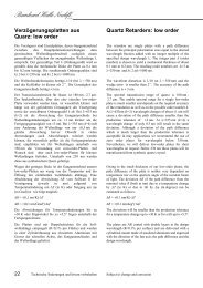
Verzögerungsplatten aus Quarz: low order 22<br />
Verzögerungsplatten aus Quarz: zero order 24<br />
Verzögerungsplatten aus MgF2: low-order 26<br />
Verzögerungsplatten aus MgF2: zero order 27<br />
Verzögerungsplatten aus Glimmer 29<br />
Achromatische Verzögerungsplatten aus Glimmer 30<br />
Achromatische Verzögerungsplatten aus Quarz, MgF2 31<br />
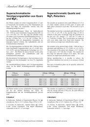
Superachromatische Verzögerungsplatten: Quarz, MgF2 34<br />
Fresnel-Rhomben 36<br />
Soleil-Babinet-Kompensatoren 41<br />
Teilkreisfassungen 44<br />
Kleine Drehfassungen 45<br />
Irisblenden 46<br />
Fassungen für Irisblenden 47<br />
Fabry-Perot-Interferometerplatten 49<br />
Etalons aus Vacodil 36 50<br />
Distanzplättchen aus Quarzglas 50<br />
Fabry-Perot Interferometergehäuse 51<br />
Planparallelplatten 52<br />
Planspiegel-Substrate 53<br />
Sphärische Hohlspiegel-Substrate 54<br />
Spiegelfassung 55<br />
90°-Prismen 56<br />
Tripelprismen 57<br />
Interferenz-Doppelprismen nach Kösters 58<br />
Strahlteilerwürfel 59<br />
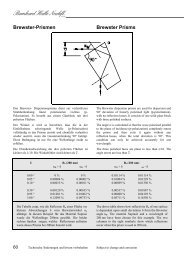
Brewster-Prismen 60<br />
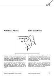
Pellin-Broca-Prismen 61<br />
Amici-Prismen 63<br />
Großes Raumfilter 64<br />
Kompakt-Raumfilter 67<br />
Laser-Raumfilterblenden 71<br />
Kurzbrennweitige sammelnde Objektive 72<br />
Kurzbrennweitige polychromatische Obj. UV, VIS, IR 73<br />
Kurzbrennweitige zerstreuende Objektive 74<br />
Langbrennweitige kollimierende Objektive 75<br />
Bestformlinsen 76<br />
Fassungen für Bestformlinsen 79<br />
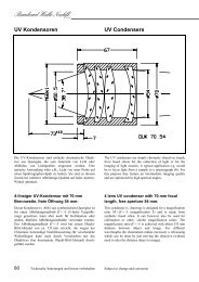
UV Kondensoren 80<br />
Achromate für fs-Pulse 82<br />
UV-VIS-IR-Apochromate 84<br />
UV Objektive für CCD-Kameras 87<br />
Sonderanfertigungen spezieller abbildender Optiken 90<br />
Index (deutsch) 92<br />
15<br />
<strong>Bernhard</strong> <strong>Halle</strong> Nachfl.<br />
GmbH<br />
New within this catalogue 2<br />
Overview of More Common Special Constructions 2<br />
Different Types of Polarizing Prisms 3<br />
Glan-Thompson Polarizing Prisms 4<br />
Glan Polarizing Prisms 7<br />
Glan Polarizing Prisms for High-Power Applications 10<br />
Foster Polarizing Beamsplitters 12<br />
<strong>Wollaston</strong> and <strong>Rochon</strong> Calcite Prisms 13<br />
<strong>Wollaston</strong> and <strong>Rochon</strong> Quartz Prisms 14<br />
UV Quartz or MgF2 <strong>Rochon</strong> Polarizers 15<br />
Polarizing Beamsplitter Cubes 17<br />
Hanle Wedge Depolarizers (Scrambler) 18<br />
Lyot Depolarizer 20<br />
Wavelength Dependencies of Retarders 21<br />
Quartz Retarders: low order 22<br />
Quartz Retarders: zero order 24<br />
MgF2 Retarders: low order 26<br />
MgF2 Retarders: zero order 27<br />
Mica Retarders 29<br />
Achromatic Mica Retarders 30<br />
Achromatic Quartz and MgF2 Retarders 31<br />
Superachromatic Quartz and MgF2 Retarders 34<br />
Fresnel Rhombs 36<br />
Soleil-Babinet Compensators 41<br />
Graduated Rotating Mounts 44<br />
Small Rotating Mounts 45<br />
Iris Diaphragms 46<br />
Holders for Iris Diaphragms 47<br />
Fabry-Perot Interferometer Plates 49<br />
Spacers in Vacodil 36 50<br />
Fused Silica Thin Spacers 50<br />
Fabry-Perot Interferometer Assemblies 51<br />
Plane Parallel Plates 52<br />
Plane Mirror Substrates 53<br />
Spherical Concave Mirror Substrates 54<br />
Mirror Mount 55<br />
Right Angle Prisms 56<br />
Solid Glass Retroreflectors 57<br />
Kösters Interference Double Prisms 58<br />
Beamsplitter Cubes 59<br />
Brewster Prisms 60<br />
Pellin-Broca Prisms 61<br />
Amici Prisms 63<br />
Large Spatial Filter 64<br />
Compact Spatial Filter 67<br />
Laser Pinholes 71<br />
Short Focal Length Focusing Objectives 72<br />
Short Focal Length Polychromatic Obj. for UV, VIS, IR 73<br />
Short Focal Length Negative Lenses 74<br />
Laser Collimating Lenses 75<br />
Best Form Lenses 76<br />
Holders for Best Form Lenses 79<br />
UV Condensers 80<br />
Achromats for fs-Pulses 82<br />
UV-VIS-IR Apochromats 84<br />
UV Objectives for CCD Cameras 87<br />
Special Imaging Optics Built to Customer Specification 90<br />
Index (english) 93<br />
1
<strong>Bernhard</strong> <strong>Halle</strong> Nachfl.<br />
GmbH<br />
Neu in diesem Katalog New within this catalogue<br />
UV Glan-Thompson-Prismen S. 6<br />
Zero-order-Platten mit Luftspalt S. 25<br />
Verzögerungsplatten aus MgF2<br />
S. 26-28<br />
Achromatische Platten mit Luftspalt S. 31-33<br />
Polychromatische Mikro-Objektive S. 73<br />
Achromatische Linsen für fs-Impulse S. 82<br />
UV-Achromate aus isotropen Materialien S. 84<br />
Kurzbrennweitiges UV Kamera-Objektiv S. 88<br />
Übersicht über häufigere<br />
Sonderanfertigungen<br />
UV Glan-Thompson prisms p. 6<br />
zero order retarders with air-space p. 25<br />
retarders made of MgF2<br />
p. 26-28<br />
achromatic retarders with air-space p. 31-33<br />
polychromatic micro objectives p. 73<br />
achromatic lenses for fs-pulses p. 82<br />
UV achromats made of isotropic materials p. 84<br />
UV imaging objective with short focal length p. 88<br />
Overview of More Common<br />
Special Constructions<br />
Polarisations-Optik Polarization optics<br />
Glan-Prismen mit dispersionsfreiem seitlichen Austritt<br />
Glan-Prismen mit Seitenfenster für 90°-Ablenkung<br />
Doppel-Glan-Prismen<br />
Brewster-Laserpolarisatoren<br />
Plattensatzpolarisatoren<br />
Kalkspatstäbe zur parallelen Strahlaufspaltung<br />
Savart-Platten<br />
Polarisationsdrehende Quarzplatten (auch für Polarimeter)<br />
Polarisations-Interferenzfilter nach Lyot-Öhman für Laser<br />
<strong>und</strong> Astronomie<br />
Glas- <strong>und</strong> Kristall-Optik für<br />
VUV, UV, VIS <strong>und</strong> IR<br />
Sphärische <strong>und</strong> zylindrische Linsen<br />
Achromatische, apochromatische <strong>und</strong> chromatische Linsensysteme,<br />
Objektive, Kollimatoren <strong>und</strong> Kondensoren<br />
Entwicklung von Sonderoptiken<br />
Laseraufweitungs-Optiken, auch für hohe Leistungen<br />
Prismen unterschiedlichster Formen <strong>und</strong> Anwendungen<br />
Littrow-Prismen, auch mit sphärischen Flächen<br />
Spiegel Mirrors<br />
Konvexspiegel Convex mirrors<br />
Glan prisms with side window for dispersion-free exit<br />
Glan prisms with side window for 90° deviation<br />
Double Glan prisms<br />
Brewster laser polarizers<br />
Pile-of-plates polarizers<br />
Calcite rods for parallel beamsplitting<br />
Savart plates<br />
Polarization rotating quartz plates (also for polarimeters)<br />
Polarization interference filters based on Lyot-Öhman for<br />
laser applications and astronomy<br />
Glass and crystal optics for<br />
VUV, UV, VIS and IR<br />
Spherical and cylindrical lenses<br />
Achromatic, apochromatic and chromatic lens systems,<br />
objectives, collimators and condensers<br />
Design of special optics<br />
Laser expansion optics, also for high-power applications<br />
Prisms of various shapes and for different applications<br />
Littrow prisms, also with spherical surfaces<br />
Mechanische Bauteile Mechanical components<br />
komplette Laseraufweitungssysteme mit oder ohne<br />
Raumfilter<br />
Soleil-Babinet Kompensator mit Motorantrieb<br />
Ein weiterer wesentlicher Teil unseres Programms sind<br />
Sonderanfertigungen <strong>und</strong> Bearbeitungen, die wir nach Ihren<br />
Wünschen oder Zeichnungen ausführen.<br />
Complete laser beam expansion systems with or without<br />
spatial filters<br />
Soleil-Babinet compensators with motor drive facility<br />
Our company also has the in-house capability to produce<br />
special constructions based on your requirements or<br />
drawings.<br />
2 Technische Änderungen <strong>und</strong> Irrtum vorbehalten Subject to change and correction
Typenübersicht von<br />
Polarisationsprismen<br />
ohne Seitenfenster<br />
without side window<br />
lange Form<br />
long form<br />
GLAN-THOMPSON-PRISMEN<br />
GLAN-PRISMEN<br />
ein Seitenfenster 72°<br />
one side window 72°<br />
Different Types of Polarizing<br />
Prisms<br />
kurze Form<br />
short form<br />
zwei Seiten- fenster 72°<br />
two side windows 72°<br />
ein Seitenfenster 90°<br />
one side window 90° großer Luftabstand<br />
large air space<br />
zwei Seitenfenster 79°/90°<br />
two side windows 79°/90°<br />
FOSTER-PRISMEN<br />
45° 90° 90°<br />
lambda/2 plate<br />
WOLLASTON ROCHON<br />
KALKSPATSTAB<br />
CALCITE ROD<br />
ROCHON UV/IR<br />
BREWSTER-POLARISATOR<br />
Technische Änderungen <strong>und</strong> Irrtum vorbehalten Subject to change and correction 3
<strong>Bernhard</strong> <strong>Halle</strong> Nachfl.<br />
GmbH<br />
Glan-Thompson<br />
Polarisationsprismen<br />
Die Prismen werden aus praktisch schlieren- <strong>und</strong><br />
blasenfreiem Kalkspat in ausgesuchter Qualität hergestellt.<br />
Der nutzbare Spektralbereich ist 300 - 2700 nm, das<br />
Löschungsvermögen ist besser als 10 -6 <strong>und</strong> die Ebenheit der<br />
Stirnflächen besser als λ/4 (λ = 550 nm). Die Deformation<br />
einer durchgehenden ebenen Welle ist kleiner als λ/4, die<br />
prismatische Ablenkung bis etwa 2'. Die Seitenflächen sind<br />
zur Absorption des totalreflektierten ordentlichen<br />
Strahlenbündels mattschwarz lackiert. Von ihnen geht nur<br />
noch ein geringes Streulicht aus, das hauptsächlich vom<br />
„gesperrten“, also an den Innenflächen reflektierten<br />
Lichtanteil stammt. Ein eventuell störender Einfluss dieses<br />
Falschlichtes kann durch einen ausreichenden Abstand<br />
zwischen Polarisator <strong>und</strong> Analysator bzw. zwischen<br />
Analysator <strong>und</strong> Empfänger vermieden werden.<br />
Die Belastbarkeit beträgt im sichtbaren Spektralbereich<br />
etwa 200 W/cm 2 cw für den durchgehenden <strong>und</strong> bis zu<br />
30 W/cm 2 cw (3 W cw) für den an der Prismenseite<br />
absorbierten Strahl.<br />
Die Glan-Thompson-Prismen sind in einer langen <strong>und</strong> einer<br />
kurzen Bauform erhältlich. Die lange Form hat ein<br />
Verhältnis von Querschnitt zu Länge von 1:3. Der Winkel<br />
zwischen Eintritts- <strong>und</strong> Innenfläche beträgt 73° <strong>und</strong> ergibt<br />
ein polarisiertes, symmetrisches Gesichtsfeld von ±15° bei<br />
550 nm. Bei der kurzen Form verhalten sich Querschnitt<br />
<strong>und</strong> Länge wie 1:2. Der Schnittwinkel beträgt 67°30' <strong>und</strong><br />
ergibt ein polarisiertes, symmetrisches Gesichtsfeld von ±6°<br />
bei 550 nm.<br />
Glan-Thompson<br />
Polarizing Prisms<br />
Lange Form: Long version:<br />
The prisms are produced from calcite of selected quality<br />
which is practically striae- and bubble-free. The usable<br />
spectral range is 300 - 2700 nm. The extinction ratio is<br />
better than 10 -6 and flatness of the outer surfaces is better<br />
than λ/4 (λ = 550 nm). The deformation of a transmitted<br />
plane wave is less than λ/4. Prismatic deviation is less than<br />
about 2'. The side faces are lacquered in matt black to<br />
absorb the totally reflected ordinary beam. Only a small<br />
amount of stray light emerges from the side faces mainly<br />
caused by the reflected („rejected“) light from the inner<br />
surface. A possibly disturbing influence of this stray light<br />
can be avoided by a sufficient distance between polarizer<br />
and analyzer or between analyzer and receiver.<br />
In the visible spectral range the maximum laser power is<br />
about 200 W/cm 2 cw for the transmitted beam and up to<br />
30 W/cm 2 cw (3 W cw) for the ray absorbed on the prism<br />
side.<br />
The Glan-Thompson prisms are available in a long and a<br />
short version. For the long version the ratio of cross section<br />
to length is 1:3. The angle between the entrance and inner<br />
faces is 73° and provides a polarized, symmetrical field of<br />
view of ±15° at 550 nm. The short version has a ratio of<br />
cross section to length equal to 1:2. The cutting angle is<br />
67°30' and provides a polarized, symmetrical field of view<br />
of ±6° at 550 nm.<br />
Prisma/Prism Fassung/Mount<br />
Öffnung Länge Aussendurchmesser freie Öffnung Länge ungefasst gefasst<br />
aperture length outer diameter free aperture length unmounted mounted<br />
7.5 x 7.2 mm² 24 mm 16 mm 7.5 mm 30 mm PGT 1.08.0 PGT 1.08<br />
7.5 x 7.2 mm² 24 mm 25 mm 7.5 mm 30 mm PGT 1.08.0 PGT 1.08.05<br />
9.5 x 9.0 mm² 30 mm 25 mm 9.5 mm 38 mm PGT 1.10.0 PGT 1.10<br />
11.5 x 10.8 mm² 36 mm 25 mm 11.5 mm 42 mm PGT 1.12.0 PGT 1.12<br />
14.5 x 13.6 mm² 45 mm 25 mm 14.5 mm 54 mm PGT 1.15.0 PGT 1.15<br />
4 Technische Änderungen <strong>und</strong> Irrtum vorbehalten Subject to change and correction
Kurze Form: Short version:<br />
Prisma/Prism Fassung/Mount<br />
Öffnung Länge Aussendurchmesser freie Öffnung Länge ungefasst gefasst<br />
aperture length outer diameter free aperture length unmounted mounted<br />
7.5 x 6.6 mm² 16 mm 16 mm 7.5 mm 22 mm PGT 2.08.0 PGT 2.08<br />
7.5 x 6.6 mm² 16 mm 25 mm 7.5 mm 22 mm PGT 2.08.0 PGT 2.08.5<br />
9.5 x 8.2 mm² 20 mm 25 mm 9.5 mm 28 mm PGT 2.10.0 PGT 2.10<br />
11.5 x 9.8 mm² 24 mm 25 mm 11.5 mm 30 mm PGT 2.12.0 PGT 2.12<br />
14.5 x 12.6 mm² 30 mm 25 mm 14.5 mm 36 mm PGT 2.15.0 PGT 2.15<br />
19.5 x 16.6 mm² 40 mm 30 mm 19.5 mm 48 mm PGT 2.20.0 PGT 2.20<br />
Kurze Form in einfacher Qualität: Short version in simple quality:<br />
Diese Prismen werden aus Kalkspat in Standardqualität<br />
hergestellt, der leichte Schlieren enthalten kann. Das<br />
Löschungsvermögen ist besser als 10 -5 , die Ebenheit der<br />
Stirnflächen besser als 1 λ; die Deformation einer<br />
durchgehenden ebenen Welle ist kleiner als 2 λ, die<br />
prismatische Ablenkung bis etwa 5'.<br />
Hohe Strahlungsdichten sollten, insbesondere unter<br />
400 nm, vermieden werden.<br />
Diese Prismen können im allgemeinen nicht in<br />
Interferometerqualität geliefert werden.<br />
Diese Prismen können auch in einer kleineren Größe<br />
(5,5 mm) angeboten werden. Die übrigen Spezifikationen<br />
entsprechen der oben beschriebenen Standardqualität.<br />
These prisms are made of standard grade calcite which may<br />
contain slight striae. The extinction ratio is better than 10 -5 .<br />
Flatness of the outer surfaces is better than 1 λ .<br />
Deformation of a transmitted plane wave is less than 2 λ.<br />
The prismatic deviation is less than about 5'.<br />
High power levels should be avoided, especially below<br />
400 nm.<br />
These prisms usually can not be supplied in interferometer<br />
quality.<br />
This quality can also be supplied in a smaller size (5.5 mm).<br />
The other specifications are the same as the ones given for<br />
the standard quality prisms described above.<br />
Prisma/Prism Fassung/Mount<br />
Öffnung Länge Aussendurchmesser freie Öffnung Länge ungefasst gefasst<br />
aperture length outer diameter free aperture length unmounted mounted<br />
5.0 x 4.5 mm² 11 mm 16 mm 5.0 mm 18 mm PGT 3.05.0 PGT 3.05<br />
7.5 x 6.6 mm² 16 mm 16 mm 7.5 mm 22 mm PGT 3.08.0 PGT 3.08<br />
9.5 x 8.2 mm² 20 mm 25 mm 9.5 mm 28 mm PGT 3.10.0 PGT 3.10<br />
Bauform entsprechend der kurzen Form.<br />
Weitere Größen auf Anfrage<br />
Dimensions are the same as for the short version.<br />
Other sizes available on request<br />
Technische Änderungen <strong>und</strong> Irrtum vorbehalten Subject to change and correction 5
<strong>Bernhard</strong> <strong>Halle</strong> Nachfl.<br />
GmbH<br />
Glan-Thompson-Prismen in UV-Qualität Glan-Thompson prisms in UV quality:<br />
Diese Prismen werden aus Kalkspat hergestellt, der auf<br />
besonders hohe UV-Transmission hin ausgesucht wurde.<br />
Die Prismenhälften sind mit UV-transparentem Kitt<br />
zusammengefügt. Der nutzbare Spektralbereich beträgt<br />
250 - 2700 nm. Das Verhältnis von Länge zu Querschnitt<br />
liegt bei 1:1,8. Die Prismen werden mit einem Winkel<br />
zwischen Eintritts- <strong>und</strong> Innenfläche von 64° gefertigt. Das<br />
polarisierte, symmetrische Gesichtsfeld beträgt ±9° bei<br />
550 nm.<br />
Die übrigen Spezifikationen entsprechen denen der oben<br />
beschriebenen Standardqualität.<br />
Für hohe Leistungen im ultravioletten Spektralbereich<br />
empfehlen wir die Verwendung von Glan-Prismen mit<br />
Luftspalt (Seite 7-10)<br />
These prisms are made of specially selected UV-grade<br />
calcite. The prisms are joined with UV transmitting cement.<br />
The usable spectral range is 250 - 2700 nm. The ratio of<br />
cross section to length is about 1:1.8. The prisms are made<br />
with an angle between the entrance and inner faces of 64°.<br />
The polarized, symmetrical field of view of ±9° at 550 nm.<br />
The other specifications are the same as the ones given for<br />
the standard quality prisms described above.<br />
For high powers in the UV we recommend to use Glan<br />
prisms with air gap (page 7-10).<br />
Prisma/Prism Fassung/Mount<br />
Öffnung Länge Aussendurchmesser freie Öffnung Länge ungefasst gefasst<br />
aperture length outer diameter free aperture length unmounted mounted<br />
7.5 x 6.5 mm² 13.5 mm 16 mm 7.5 mm 22 mm PGT 4.08.0 PGT 4.08<br />
7.5 x 6.5 mm² 13.5 mm 25 mm 7.5 mm 22 mm PGT 4.08.0 PGT 4.08.5<br />
9.5 x 8.5 mm² 17.5 mm 25 mm 9.5 mm 28 mm PGT 4.10.0 PGT 4.10<br />
11.5 x 10.4 mm² 21.5 mm 25 mm 11.5 mm 30 mm PGT 4.12.0 PGT 4.12<br />
14.5 x 13.0 mm² 27.0 mm 25 mm 14.5 mm 36 mm PGT 4.15.0 PGT 4.15<br />
19.5 x 17.4 mm² 36.0 mm 30 mm 19.5 mm 48 mm PGT 4.20.0 PGT 4.20<br />
Zusätzliche Angaben: Please note:<br />
Die Prismen können zur Winkelorientierung in Drehfassungen<br />
(Seite 44/45) aufgenommen werden.<br />
For angular orientation these prisms can be mounted in the<br />
Rotating Mounts (page 44/45).<br />
Sonderanfertigungen: Available on special order:<br />
Interferometerqualität: Interferometer quality:<br />
Deformation einer durchgehenden ebenen Welle kleiner als<br />
λ/10, Ebenheit der Stirnflächen λ/10, Ablenkung kleiner<br />
als 5" PGT 0.1<br />
Löschungsvermögen besser als 10 -7 PGT 0.7<br />
Löschungsvermögen besser als 10 -8 PGT 0.8<br />
Entspiegelung der Prismen (Die Prismen in<br />
Interferometerqualität können nur ohne Entspiegelung<br />
geliefert werden) auf Anfrage<br />
Deformation of a transmitted plane wave less than λ/10.<br />
Flatness of outer surfaces λ/10. Deviation less than 5"<br />
PGT 0.1<br />
Extinction ratio better than 10 -7 PGT 0.7<br />
Extinction ratio better than 10 -8 PGT 0.8<br />
Antireflection coating (The prisms in interferometer quality<br />
can only be supplied without antireflection coating)<br />
on request<br />
6 Technische Änderungen <strong>und</strong> Irrtum vorbehalten Subject to change and correction
Glan-Polarisationsprismen Glan Polarizing Prisms<br />
Die Prismen werden aus praktisch schlieren- <strong>und</strong><br />
blasenfreiem Kalkspat hergestellt. Die Prismenhälften sind<br />
in einem Luftabstand von ca. 0,07 mm montiert <strong>und</strong> werden<br />
standardmäßig mit einer Fassung geliefert.<br />
Das Löschungsvermögen ist mindestens 10 -5 für das<br />
geradeaus durchgehende Bündel, die Ebenheit der<br />
Stirnflächen ist besser als λ/2 (λ = 550 nm), die<br />
Deformation einer durchgehenden ebenen Welle ist kleiner<br />
als λ/2 <strong>und</strong> die prismatische Ablenkung beträgt bis zu 2'.<br />
Der nutzbare Spektralbereich der Standardprismen ist etwa<br />
300 bis 2700 nm (oberhalb von 2 µm beginnt Absorption<br />
für den abgelenkten Strahl). Das Gesichtsfeld ist<br />
gleichmäßig polarisiert in einem Bereich von etwa 13°-<br />
7,5°, es ist jedoch nur bei einer Wellenlänge symmetrisch<br />
zum Einfallslot.<br />
Es werden zwei Prismentypen gefertigt, die sich durch die<br />
Wellenlänge unterscheiden, bei der das Gesichtsfeld<br />
symmetrisch ist (s. Diagramm unten).<br />
1) λsym beträgt 700 nm, Gesichtsfeld ± 4°. Bei 350 nm <strong>und</strong><br />
2 µm beträgt das symmetrisch nutzbare Gesichtsfeld ± 3,0°.<br />
2) λsym beträgt 400 nm, Gesichtsfeld ± 4,3°. Bei 290 nm<br />
<strong>und</strong> 560 nm beträgt das symmetrisch nutzbare Gesichtsfeld<br />
± 3,3°.<br />
Bei diesen Prismen tritt an den Innenflächen ein<br />
Lichtverlust durch Fresnel-Reflexion auf, der pro<br />
Innenfläche etwa 5% beträgt (Typ 1, 1064 nm).<br />
Die Glan-Prismen werden auch mit Seitenfenstern gefertigt,<br />
durch die die reflektierten Strahlen unter Winkeln von<br />
ca. 72° austreten. In den Fassungen sind dafür<br />
entsprechende Öffnungen angebracht.<br />
Die Ebenheit der seitlichen Austrittsflächen beträgt etwa<br />
3 λ.<br />
The prisms are made of calcite which is practically striae-<br />
and bubble-free. The prism halves are separated by an air<br />
gap of approx. 0.07 mm and are supplied mounted in a<br />
holder as standard.<br />
The extinction ratio is a minimum of 10 -5 for the <strong>und</strong>eviated<br />
ray. Flatness of the outer surfaces is better than λ/2<br />
(λ = 550 nm). Deformation of a transmitted plane wave is<br />
less than λ/2 and prismatic deviation less than about 2'.<br />
The usable spectral range of the standard prisms is 300 to<br />
2700 nm (absorption of the deflected beam occurs above<br />
2 µm). The polarization effect is maintained in a field of<br />
view of about 13° to 7.5° but is symmetrical to the normal<br />
of the input surface only on one wavelength.<br />
Two types of prisms are manufactured; they differ from one<br />
another by the wavelength which has the symmetrical field<br />
of view (see diagram below).<br />
1) λsym = 700 nm, field of view ± 4°. At 350 nm and 2 µm<br />
the symmetrically usable field of view is ± 3.0°.<br />
2) λsym = 400 nm, field of view ± 4.3°. At 290 nm and<br />
560 nm the symmetrically usable field of view is ± 3.3°.<br />
Due to Fresnel reflection on the inner surfaces there is a<br />
light loss of about 5% per inner surface (Type 1, 1064 nm).<br />
Glan prisms are also produced with side exit windows<br />
through which the reflected beams exit at angles of<br />
approx. 72°. The holders for these prisms have side holes<br />
to allow the reflected beams to escape.<br />
The flatness of the side exit surfaces is aro<strong>und</strong> 3 λ.<br />
Technische Änderungen <strong>und</strong> Irrtum vorbehalten Subject to change and correction 7
<strong>Bernhard</strong> <strong>Halle</strong> Nachfl.<br />
GmbH<br />
Prisma/Prism Fassung/Holder ohne Seitenfenster mit zwei Seitenfenstern<br />
Öffnung Länge Durchmesser without side exit window with two side exit windows<br />
aperture length diameter Länge/length Länge/length<br />
9.5 mm 10 mm 25 mm 22 mm PGL 10 22 mm PGL 10.2<br />
11.5 mm 12 mm 25 mm 30 mm PGL 12 30 mm PGL 12.2<br />
14.5 mm 15 mm 25 mm 30 mm PGL 15 30 mm PGL 15.2<br />
19.5 mm 20 mm 36 mm 30 mm PGL 20 40 mm PGL 20.2<br />
24.5 mm 25 mm 45 mm 32 mm PGL 25 43 mm PGL 25.2<br />
29.5 mm 30 mm 50 mm 42 mm PGL 30 42 mm PGL 30.2<br />
Nutzbare Öffnungswinkel von<br />
Glan Prismen<br />
Einfache Qualität: Simple quality:<br />
Diese Prismen werden aus Kalkspat in Standardqualität<br />
hergestellt. Das Löschungsvermögen ist etwa 10 -5 für das<br />
geradeaus durchgehende Bündel, die Ebenheit der<br />
Stirnflächen ist besser als 1 λ, die Deformation einer<br />
durchgehenden ebenen Welle ist kleiner als 2 λ <strong>und</strong> die<br />
prismatische Ablenkung beträgt bis zu 5'.<br />
Usable aperture angles of Glan prisms<br />
αe <strong>und</strong> αo sind die Grenzwinkel der Totalreflexion. Innerhalb<br />
dieser Grenzwinkel ist das durchgehende Licht polarisiert.<br />
Licht mit Einfallswinkeln |α| > |αe| wird am Luftspalt total<br />
reflektiert. Licht (beide Polarisationsrichtungen) mit |α| > |αo|<br />
wird durchgelassen <strong>und</strong> daher nicht mehr polarisiert, der<br />
nutzbare Öffnungswinkel ist überschritten.<br />
αe and αo are the critical angles for total internal reflection at<br />
the inner surface. The transmitted light is polarized when the<br />
incidence angle lies between these two limits. All rays with<br />
angles of incidence |α| > |αe| are totally reflected at the air gap.<br />
All rays (both polarization directions) with |α| > |αo| will be<br />
transmitted and be superimposed to the polarized light: the<br />
usable acceptance angle of the prism is exceeded.<br />
These prisms are produced from standard grade calcite. The<br />
extinction ratio is about 10 -5 for the <strong>und</strong>eviated ray. Flatness<br />
of the outer surfaces is better than 1 λ. Deformation of a<br />
transmitted plane wave is less than 2 λ and prismatic<br />
deviation is a maximum of 5'.<br />
8 Technische Änderungen <strong>und</strong> Irrtum vorbehalten Subject to change and correction
Der nutzbare Spektralbereich ist etwa 350 bis 2700 nm, <strong>und</strong><br />
es muss mit stärkerer Absorption <strong>und</strong> Fluoreszenz<br />
gerechnet werden. Die Prismen werden nur mit der<br />
Symmetriewellenlänge 700 nm gefertigt.<br />
Die optionalen seitlichen Austrittsfenster besitzen eine<br />
Ebenheit von etwa 10 λ.<br />
Diese Prismen können im allgemeinen nicht in<br />
Interferometerqualität geliefert werden.<br />
In principle the usable spectral range is about 350 to<br />
2700 nm, as for the standard version, and there is the risk of<br />
a higher rate of absorption and fluorescence. The prisms<br />
only are manufactured with λsym = 700 nm.<br />
The optional side windows are polished to flatness of about<br />
10 λ.<br />
These prisms usually are not produced in interferometer<br />
quality.<br />
Prisma/Prism Fassung/Holder ohne Seitenfenster mit zwei Seitenfenstern<br />
Öffnung Länge Durchmesser Länge without side exit window with two side exit windows<br />
aperture length diameter length<br />
9.5 mm 10 mm 25 mm 22 mm PGL 2.10 PGL 2.10.2<br />
Zusätzliche Angaben: Please note:<br />
Die Prismen können zur Winkelorientierung in Drehfassungen<br />
(Seite 44/45) aufgenommen werden.<br />
For angular orientation these prisms can be mounted in the<br />
Rotating Mounts (page 44/45).<br />
Sonderanfertigungen: Available on special order:<br />
Entspiegelungen der Ein- <strong>und</strong> Austrittsflächen<br />
auf Anfrage<br />
Löschungsvermögen besser als 10 -6 PGL 0.6<br />
Interferometerqualität (auf Seite 11 erläutert) PGL 0.1<br />
Für Anwendungen, die weniger Gesichtsfeld benötigen<br />
(z.B. Laser), können die Prismen auch mit an die<br />
Wellenlänge angepasstem Schnittwinkel so modifiziert<br />
werden, dass die Innenflächen nahe dem Brewsterwinkel<br />
durchstrahlt werden <strong>und</strong> so die inneren Fresnel-Verluste<br />
deutlich reduziert werden können. auf Anfrage<br />
Prismen mit nur einem Seitenfenster auf Anfrage<br />
Antireflection coatings for entrance and exit surfaces<br />
on request<br />
Extinction ratio better than 10 -6 PGL 0.6<br />
Interferometer quality (described on page 11) PGL 0.1<br />
The prisms can also be modified by an individual inner<br />
cutting angle (wavelength dependent) so that the inner<br />
surfaces are transmitted close to the Brewster angle. This<br />
helps to reduce the Fresnel reflection on the inner surfaces,<br />
however it is only possible for applications that need less<br />
field of view (e.g. lasers). on request<br />
Prisms with only one side window on request<br />
Technische Änderungen <strong>und</strong> Irrtum vorbehalten Subject to change and correction 9
<strong>Bernhard</strong> <strong>Halle</strong> Nachfl.<br />
GmbH<br />
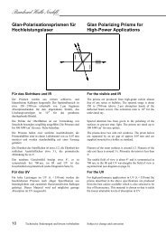
Glan-Polarisationsprismen für<br />
Hochleistungslaser<br />
Glan Polarizing Prisms for<br />
High-Power Applications<br />
Für das Sichtbare <strong>und</strong> IR For the visible and IR<br />
Die Prismen werden aus extrem schlieren- <strong>und</strong><br />
blasenfreiem Kalkspat hergestellt. Der Spektralbereich ist<br />
etwa 350 - 2700 nm (oberhalb von 2 µm beginnen<br />
Absorptionsbanden für den abgelenkten Strahl), das<br />
Löschungsvermögen ist 10 -6 für das geradeaus<br />
durchgehende Bündel.<br />
Die Politur der Oberflächen ist zur Vermeidung von<br />
Streulicht besonders sorgfältig ausgeführt. Die Prismen sind<br />
bis 300 MW/cm 2 für nsec- Pulse belastbar.<br />
Die Prismen haben zwei seitliche Austrittsfenster, die<br />
Prismenhälften sind in einem Luftabstand von ca. 0,07 mm<br />
montiert <strong>und</strong> werden standardmäßig mit einer Fassung<br />
geliefert.<br />
Die Ebenheit der Stirnflächen ist etwa λ/2, die Ebenheit der<br />
seitlichen Austrittsflächen etwa 3 λ, die prismatische<br />
Ablenkung bis zu 2'.<br />
Das nutzbare Gesichtsfeld beträgt etwa 8°, es ist<br />
symmetrisch bei 700 nm, im IR <strong>und</strong> UV ist das<br />
Gesichtsfeld unsymmetrisch (siehe Diagramm Seite 8).<br />
Für das UV For the UV<br />
Für hohe Leistungen im UV (λ < 350 nm) werden die<br />
beschriebenen Prismen nach obiger Spezifikation aus<br />
bestmöglichem <strong>und</strong> zusätzlich fluoreszenzfreiem Kalkspat<br />
gefertigt. Dieses Material wird auf möglichst geringe<br />
Absorption im UV ausgesucht.<br />
The prisms are produced from high-grade calcite almost<br />
free of any striae or bubbles. The spectral range is about<br />
350 to 2700 nm (above 2 µm absorption bands of the<br />
deflected beam occur). The extinction ratio is 10 -6 for the<br />
<strong>und</strong>eviated ray.<br />
Special attention has been given to the polishing of the<br />
surfaces to prevent stray light. The prisms are rated up to<br />
300 MW/cm 2 for nsec-pulses.<br />
The prisms have two side exit windows. The prism halves<br />
are separated by an air gap of approx. 0.07 mm and are<br />
supplied mounted in a holder as standard.<br />
Flatness of the outer surfaces is aro<strong>und</strong> λ/2. Flatness of the<br />
side exit faces is aro<strong>und</strong> 3 λ. Prismatic deviation is less than<br />
2'.<br />
The usable field of view is about 8° and is symmetrical at<br />
700 nm; in the IR and UV wavelengths the field of view is<br />
asymmetrical (see diagram on page 8).<br />
For high-performance applications in UV (λ < 350 nm) the<br />
prisms described in the above specifications are produced<br />
from the best calcite available which is also selected to be<br />
free of fluorescence. This material is chosen so that it yields<br />
the lowest attainable levels of absorption in UV.<br />
10 Technische Änderungen <strong>und</strong> Irrtum vorbehalten Subject to change and correction
Interferometerqualität: Interferometer quality:<br />
Ausführung wie oben, jedoch sind zusätzlich die<br />
Lichteintritts-, Austritts- <strong>und</strong> die Innenflächen mit einer<br />
Ebenheit von λ/10 poliert (Ebenheit der Seitenfenster etwa<br />
3 λ). Die Deformation einer durchgehenden ebenen Welle<br />
ist kleiner als λ/10.<br />
Same specifications as above except that the light entrance,<br />
exit, and inner faces are polished to a flatness of λ/10<br />
(flatness of side exit window aro<strong>und</strong> 3 λ). Deformation of a<br />
transmitted plane wave is less than λ/10.<br />
Prisma/Prism Fassung/Holder VIS-IR UV<br />
Öffnung Länge Durchmesser Länge Normal- Interferometer- Normal- Interferometer-<br />
aperture length diameter length qualität/quality qualität/quality qualität/quality qualität/quality<br />
9.5 mm 10 mm 25 mm 21.5 mm PGH 10 PGH 10.10 PGU 10 PGU 10.10<br />
11.5 mm 12 mm 25 mm 30.0 mm PGH 12 PGH 12.10 PGU 12 PGU 12.10<br />
14.5 mm 15 mm 25 mm 30.0 mm PGH 15 PGH 15.10 PGU 15 PGU 15.10<br />
Sonderanfertigungen: Available on special order:<br />
Die Prismen können in eine Kastenfassung mit großem<br />
Luftspalt eingesetzt werden, um die Reflexe an den<br />
Innenflächen aus dem Strahlengang zu leiten. PGH 0<br />
Entspiegelungen auf Anfrage<br />
These prisms can be set in a box mount with a large air gap<br />
to direct the reflection on the inner surfaces out of the<br />
prism. PGH 0<br />
Antireflection coatings on request<br />
Technische Änderungen <strong>und</strong> Irrtum vorbehalten Subject to change and correction 11
<strong>Bernhard</strong> <strong>Halle</strong> Nachfl.<br />
GmbH<br />
Foster-<br />
Polarisationsstrahlenteiler<br />
Die Prismen erzeugen zwei senkrecht zueinander<br />
polarisierte Strahlenbündel. Sie sind aus schlieren- <strong>und</strong><br />
blasenfreiem Kalkspat hergestellt. Der Winkel zwischen<br />
den austretenden Strahlenbündeln ist 45° oder 90° ± 3', der<br />
nutzbare Spektralbereich ist 300 - 2700 nm (oberhalb von<br />
2 µm beginnt Absorption für den abgelenkten Strahl).<br />
Das Gesichtsfeld beträgt ± 6° bei 550 nm, das<br />
Löschungsvermögen ist 10 -6 für das geradeaus<br />
durchgehende Strahlenbündel, jedoch deutlich geringer für<br />
das abgelenkte Bündel. Die Ebenheit der Stirnflächen ist<br />
besser als λ/2 (λ = 550 nm), die Deformation einer<br />
durchgehenden ebenen Welle kleiner als λ/2 <strong>und</strong> die<br />
prismatische Ablenkung des durchgehenden Strahls beträgt<br />
bis etwa 2'.<br />
Die Prismen werden standardmäßig in Kastenfassungen<br />
geliefert.<br />
Foster Polarizing Beamsplitters<br />
The prisms produce two beams polarized perpendicular to<br />
each other. They are produced from high-grade calcite free<br />
of striae and bubbles. The angle between the emerging<br />
beams is 45° or 90° ± 3'. The usable spectral range is 300 to<br />
2700 nm (absorption of the deflected beam occurs above<br />
2 µm).<br />
The field of view is ± 6° at 550 nm. The extinction ratio is<br />
10 -6 for the <strong>und</strong>eviated beam but not as good for the<br />
reflected beam. Flatness of the outer surfaces is better than<br />
λ/2 (λ = 550 nm). Deformation of a transmitted plane wave<br />
is less than λ/2, and prismatic deviation of the transmitted<br />
beam is less than about 2'.<br />
The prisms are supplied in a box mount as standard.<br />
Prisma/Prism Fassung/Holder Ablenkung/Deviation<br />
Öffnung Länge Querschnitt Länge<br />
aperture length cross-section length 45° 90°<br />
6 mm 16 mm 18,0 x 14 mm 20 mm PFO 45.06<br />
8 mm 20 mm 22,6 x 18 mm 26 mm PFO 45.08 PFO 90.08<br />
10 mm 24 mm 25,0 x 18 mm 30 mm PFO 45.10 PFO 90.10<br />
12 mm 30 mm 29,0 x 20 mm 36 mm PFO 45.12 PFO 90.12<br />
Sonderanfertigungen: Available on special order:<br />
Auf Wunsch kann eine λ/2-Verzögerungsplatte auf das<br />
Seitenfenster gekittet werden. Eine solche Platte dreht (für<br />
eine Wellenlänge) die Schwingungsrichtung um 90°, so<br />
dass beide austretenden Strahlenbündel in der gleichen<br />
Richtung polarisiert sind. auf Anfrage<br />
Entspiegelungen auf Anfrage<br />
If required, a λ/2 retardation plate can be cemented onto the<br />
side window. This plate (for one wavelength) rotates the<br />
polarization direction by 90° so that both emerging beams<br />
are polarized in the same direction. on request<br />
Antireflection coatings on request<br />
12 Technische Änderungen <strong>und</strong> Irrtum vorbehalten Subject to change and correction
<strong>Wollaston</strong>- <strong>und</strong> <strong>Rochon</strong>-<br />
Prismen aus Kalkspat<br />
Die Prismen werden aus schlieren- <strong>und</strong> blasenfreiem<br />
Material hergestellt. Der nutzbare Spektralbereich ist<br />
300 - 2200 nm (oberhalb von 2 µm beginnt Absorption für<br />
den ordentlichen Strahl). Die Prismenhälften sind verkittet,<br />
der Ablenkfehler geht bis etwa 1', die Ebenheit der<br />
Außenflächen ist λ/2 für λ = 550 nm. Die Deformation<br />
einer durchgehenden ebenen Welle ist kleiner als 1 λ, das<br />
Löschungsvermögen für beide Bündel 10 -6 . Die Schwingungsrichtungen<br />
der beiden senkrecht zueinander polarisierten<br />
Bündel laufen parallel <strong>und</strong> senkrecht zur brechenden<br />
Kante. Die Prismen mit 10 mm Querschnitt haben<br />
quadratische Form, ab 15 mm ist der Querschnitt achteckig.<br />
Die mechanisch empfindliche achsensenkrechte Fläche<br />
des <strong>Rochon</strong>-Prismas ist mit einer aufgekitteten Deckplatte<br />
aus Quarzglas Suprasil, Ebenheit λ/10, geschützt.<br />
Zur Anordnung der <strong>Rochon</strong>-Prismen als Polarisator bzw.<br />
Analysator siehe Seite 15.<br />
e<br />
o<br />
<strong>Wollaston</strong> and <strong>Rochon</strong> Calcite<br />
Prisms<br />
The prisms are produced from material free of striae and<br />
bubbles. The usable spectral range is 300 - 2200 nm<br />
(absorption of the ordinary beam occurs above 2µm). The<br />
two prism halves are cemented together. Deviation is less<br />
than about 1'. Flatness of the outer surfaces is λ/2 for<br />
λ = 550 nm. Deformation of a transmitted plane wave is<br />
less than 1 λ. The extinction ratio of both beams is 10 -6 . The<br />
polarization direction of both beams polarized<br />
perpendicular to each other is parallel and vertical to the<br />
refracting edge. The prisms with a 10mm cross-section are<br />
square in shape; above 15mm the cross-section is<br />
octagonal. The axis perpendicular entrance surface of<br />
<strong>Rochon</strong> prisms (which is mechanically very sensitive) is<br />
protected by a cemented covering plate of fused silica<br />
Suprasil with a flatness of λ/10.<br />
See page 15 for a note on orientations of <strong>Rochon</strong> prisms<br />
used as polarizers resp. analyzers.<br />
Prismenquerschnitt Divergenzwinkel (Standardwerte im Sichtbaren)<br />
Cross-section of prism Divergence angles (Standard values in the visible)<br />
<strong>Wollaston</strong> <strong>Rochon</strong><br />
5° 10° 20° 2.5° 5° 10°<br />
10 x 10 mm PWK 5.10 PWK 10.10 PWK 20.10 PRK 2.10 PRK 5.10 PRK 10.10<br />
15 x 15 mm PWK 5.15 PWK 10.15 PWK 20.15 PRK 2.15 PRK 5.15 PRK 10.15<br />
20 x 20 mm PWK 5.20 PWK 10.20 PWK 20.20 PRK 2.20 PRK 5.20 PRK 10.20<br />
25 x 25 mm PWK 5.25 PWK 10.25 PWK 20.25 PRK 2.25 PRK 5.25 PRK 10.25<br />
30 x 30 mm PWK 5.30 on request on request PRK 2.30 on request on request<br />
Andere Divergenzwinkel bei Einzelbestellung,<br />
Mehrpreis PWK 1, PRK 1<br />
Zylindrische Fassung mit Gravur des Divergenzwinkels<br />
PWK 0, PRK 0<br />
Other divergence angles have a surchage if ordered in<br />
a single quantity PWK 1, PRK 1<br />
Cylindrical holder engraved with respective divergence<br />
angle PWK 0, PRK 0<br />
Sonderanfertigungen: Available on special order:<br />
Entspiegelungen auf Anfrage<br />
Dreiteilige <strong>Wollaston</strong>-Prismen für Divergenzwinkel bis<br />
ca. 30° auf Anfrage<br />
Lage der Schwingungsrichtung der polarisierten Bündel<br />
± 45° zur brechenden Kante auf Anfrage<br />
Antireflection coatings on request<br />
Three-part <strong>Wollaston</strong> prisms for divergence angles up to<br />
approx. 30° on request<br />
Orientation of polarization direction of the polarized beams<br />
± 45° to the refracting edge on request<br />
Technische Änderungen <strong>und</strong> Irrtum vorbehalten Subject to change and correction 13<br />
e<br />
o
<strong>Bernhard</strong> <strong>Halle</strong> Nachfl.<br />
GmbH<br />
<strong>Wollaston</strong>- <strong>und</strong> <strong>Rochon</strong>-<br />
Prismen aus Quarz<br />
Die Prismen werden aus schlieren- <strong>und</strong> blasenfreiem<br />
Material hergestellt. Der nutzbare Spektralbereich ist 0,23 -<br />
2,8 µm. Die Prismenhälften sind mit optischem Kontakt<br />
verb<strong>und</strong>en, die Ebenheit der Außenflächen ist λ/10 für<br />
λ = 550 nm <strong>und</strong> die Deformation einer durchgehenden<br />
ebenen Welle kleiner als λ/5. Das Löschungsvermögen ist<br />
für beide Bündel 10 -5 .<br />
Die Schwingungsrichtungen der beiden senkrecht<br />
zueinander polarisierten Bündel sind parallel <strong>und</strong> senkrecht<br />
zur brechenden Kante. Der Querschnitt ist quadratisch, bei<br />
größeren Prismen achteckig.<br />
Zur Anordnung der <strong>Rochon</strong>-Prismen als Polarisator bzw.<br />
Analysator siehe Anmerkung auf Seite 15.<br />
o<br />
e<br />
<strong>Wollaston</strong> and <strong>Rochon</strong> Quartz<br />
Prisms<br />
The prisms are produced from high-grade material free of<br />
striae and bubbles. The usable spectral range is<br />
0.23 -2.8 µm. The two prism halves are optically contacted.<br />
Flatness of the outer faces is λ/10 for λ = 550 nm and<br />
deformation of a transmitted plane wave is less than λ/5.<br />
The extinction ratio of both beams is 10 -5 .<br />
The polarization direction of both beams polarized<br />
perpendicular to each other is parallel and vertical to the<br />
refracting edge. The cross-section is square; in larger<br />
prisms it is octagonal.<br />
See page 15 for a note on the orientations of <strong>Rochon</strong> prisms<br />
used as polarizers and analyzers.<br />
Prismenquerschnitt Divergenzwinkel (Standardwerte im Sichtbaren)<br />
Cross-section of prism Divergence angles (Standard values in the visible)<br />
<strong>Wollaston</strong> <strong>Rochon</strong><br />
30' 60' 15' 30'<br />
10 x 10 mm PWQ 30.10 PWQ 60.10 PRQ 15.10 PRQ 30.10<br />
15 x 15 mm PWQ 30.15 PWQ 60.15 PRQ 15.15 PRQ 30.15<br />
20 x 20 mm PWQ 30.20 PWQ 60.20 PRQ 15.20 PRQ 30.20<br />
25 x 25 mm PWQ 30.25 PWQ 60.25 PRQ 15.25 PRQ 30.25<br />
30 x 30 mm PWQ 30.30 PWQ 60.30 PRQ 15.30 PRQ 30.30<br />
Andere Divergenzwinkel, bei Einzelbestellung,<br />
Mehrpreis PWQ 1, PRQ 1<br />
Zylindrische Fassung mit Gravur des Divergenzwinkels<br />
PWQ 0, PRQ 0<br />
Other divergence angles have a surcharge if ordered in<br />
a single quantity PWQ 1, PRQ 1<br />
Cylindrical holder engraved with respective divergence<br />
angle PWQ 0, PRQ 0<br />
Sonderanfertigungen: Available on special order:<br />
Für die Anwendung in Differential-Interferometern können<br />
die <strong>Wollaston</strong>prismen paarig mit besonders geringer Dicke<br />
hergestellt werden. PWQ 0.11<br />
Lage der Schwingungsrichtung der polarisierten Bündel<br />
± 45° zur brechenden Kante PWQ 0.45<br />
Prismen für Wellenlängen ab 180 nm auf Anfrage<br />
Entspiegelungen auf Anfrage<br />
Größere Prismen auf Anfrage<br />
<strong>Wollaston</strong> prisms can be produced in pairs with minimal<br />
thickness for use in differential interferometers.<br />
PWQ 0.11<br />
Orientation of the polarization direction of the polarized<br />
beams ± 45° to the refracting edge PWQ 0.45<br />
Prisms for wavelengths above 180 nm on request<br />
Antireflection coatings on request<br />
Larger prisms on request<br />
14 Technische Änderungen <strong>und</strong> Irrtum vorbehalten Subject to change and correction<br />
o<br />
e
UV-Polarisatoren nach <strong>Rochon</strong><br />
aus Quarz oder MgF2<br />
Die Prismen werden aus bestem synthetischen UV-Material<br />
gefertigt. Die Prismenhälften sind mit optischem Kontakt<br />
verb<strong>und</strong>en, die Ebenheit der Außenflächen ist λ/10 für<br />
λ = 550 nm <strong>und</strong> die Deformation einer durchgehenden<br />
ebenen Welle kleiner als λ/5. Das Löschungsvermögen ist<br />
mindestens 10 -5<br />
Die Prismen werden in einer vakuumtauglichen,<br />
zylindrischen Fassung mit belüfteten Hohlräumen geliefert.<br />
Der ordentliche Strahl durchsetzt das Prisma ohne<br />
Ablenkung (mit einem Fehler bis zu 3'). Auf der Fassung ist<br />
die Schwingungsrichtung des elektrischen Vektors des<br />
ordentlichen Strahls graviert. An der gravierten Seite der<br />
Fassung liegt auch die parallel zur optischen Achse des<br />
Kristalls geschnittene Stirnfläche des Prismas.<br />
Für die Divergenzwinkel ergeben sich die in der Tabelle<br />
angegebenen Werte:<br />
UV Quartz or MgF2 <strong>Rochon</strong><br />
Polarizers<br />
The prisms are produced from the highest quality synthetic<br />
UV material available. The two prisms are optically<br />
contacted. Flatness of the outer faces is λ/10 for λ = 550 nm<br />
and deformation of the transmitted plane wave is less than<br />
λ/5. The extinction ratio is at least 10 -5 .<br />
The prisms are mounted in a vacuum compatible cylindrical<br />
holder with vented air spaces.<br />
The ordinary beam passes through the prism without<br />
deviation (with an error less than about 3'). The direction of<br />
polarization of the electric field vector of the ordinary beam<br />
is engraved on the holder. The surface of the prism in<br />
which the optical axis of the crystal lies parallel to the<br />
surface is oriented towards the engraved side of the holder.<br />
The wavelength dependence of the divergence angles is<br />
given in the following table:<br />
Divergenzwinkel<br />
Divergence angles<br />
λ Quarz/Quartz MgF2<br />
130 nm 2.19 °<br />
150 nm 2.63 °<br />
175 nm 2.57 °<br />
185 nm 2.63 ° 2.53 °<br />
200 nm 2.42 ° 2.49 °<br />
400 nm 1.80 ° 2.24 °<br />
500 nm 1.74 ° 2.21 °<br />
2500 nm 1.48 ° 2.04 °<br />
6000 nm 1.40 °<br />
Wichtiger Hinweis zum Einbau: Important note for integration:<br />
Zur Verwendung als Polarisator (d.h. um polarisiertes Licht<br />
hinter dem Prisma zu erhalten) muss das Licht auf der nicht<br />
gravierten Seite der Fassung einfallen. Bei Verwendung als<br />
Analysator (d.h. um die Polarisations-Eigenschaften<br />
einfallenden Lichtes zu analysieren) muss die gravierte<br />
Seite zum einfallenden Licht weisen. Bei einem Polarisator-<br />
Analysator-Paar müssen also die Gravuren zueinander<br />
zeigen.<br />
When the prism is used as a polarizer (i.e. to achieve<br />
polarized light after the prism) the light must enter the side<br />
which is not engraved. When the prism however is used as<br />
an analyzer (i.e. to analyze the polarisation of incident<br />
light) the engraved side must be directed towards the<br />
incident light. Thus, when used in a pair as polarizer and<br />
analyzer the engravings of the holders must face each other.<br />
Technische Änderungen <strong>und</strong> Irrtum vorbehalten Subject to change and correction 15
<strong>Bernhard</strong> <strong>Halle</strong> Nachfl.<br />
GmbH<br />
Prisma/Prism Fassung/Holder Quarz/Quartz MgF2<br />
Öffnungsdurchmesser Länge Durchmesser Länge<br />
diameter of aperture length diameter length<br />
8 mm 29 mm 25 mm 38 mm PUQ 08 PUM 08<br />
10 mm 36 mm 25 mm 45 mm PUQ 10 PUM 10<br />
12 mm 42 mm 25 mm 53 mm PUQ 12 PUM 12<br />
15 mm 52 mm 25 mm 57 mm PUQ 15 PUM 15<br />
Die Prismen PUQ sind aus synthetischem Quarz hergestellt,<br />
der nutzbare Spektralbereich reicht etwa von 180 nm bis<br />
2,8 µm.<br />
Die Prismen PUM sind aus MgF2 (VUV-Material)<br />
hergestellt, der nutzbare Spektralbereich reicht etwa von<br />
150 nm bis 6 µm.<br />
Ausführung mit Luftspalt für<br />
Hochleistungs-Laser:<br />
Für hohe Leistungen im UV wird jeweils eine Ausführung<br />
mit Luftabstand gefertigt, bei der die Innenflächen unter<br />
dem Brewster-Winkel durchstrahlt werden, so dass der<br />
ordentliche Strahl ohne Reflexionsverluste durch die<br />
Innenflächen geht.<br />
Prisms PUQ are produced from synthetic quartz. The usable<br />
spectral range is approx. from 180 nm to 2.8 µm.<br />
Prisms PUM are made of MgF2 (VUV material). The<br />
usable spectral range is approx. from 150 nm to 6 µm.<br />
Air-spaced version for high-power laser<br />
applications:<br />
For high-power applications in UV an air-spaced version is<br />
produced in which the inner faces are passed almost at the<br />
Brewster angle so that the ordinary beam traverses the inner<br />
faces without reflection losses.<br />
Prisma/Prism Fassung/Holder Quarz/Quartz MgF2<br />
Öffnungsdurchmesser Länge Durchmesser Länge<br />
diameter of aperture length diameter length<br />
9.5 mm 11 mm 25 mm 18 mm PLQ 10 PLM 10<br />
14.5 mm 13 mm 25 mm 18 mm PLQ 15 PLM 15<br />
Bei den Prismen aus Quarz ist die Ablenkung des<br />
außerordentlichen Strahles 0,4° (250 nm), bei MgF2 0,55°<br />
(150 nm).<br />
The deviation of the extraordinary beam is 0.4° (250 nm)<br />
for the quartz prisms and 0.55° (150 nm) for the MgF2<br />
prisms.<br />
16 Technische Änderungen <strong>und</strong> Irrtum vorbehalten Subject to change and correction
Polarisations-Strahlteilerwürfel Polarizing Beamsplitter Cubes<br />
Zwei 90°-Prismen aus Flintglas sind zu einem Würfel<br />
verkittet.<br />
Die dielektrische Teilungsschicht hat im Bereich von<br />
440 - 650 nm für die parallel zur Einfallsebene<br />
schwingende Komponente eine Transmission von 97% -<br />
98%. Im durchgehenden Licht ist ein Anteil von weniger<br />
als 0,04% senkrecht zur Einfallsebene polarisierter<br />
Strahlung enthalten. Für die senkrecht zur Einfallsebene<br />
schwingende, um 90° abgelenkte Komponente beträgt das<br />
Reflexionsvermögen 99,9%. Das reflektierte Licht enthält<br />
2 - 3% parallel zur Einfallsebene polarisierte Strahlung.<br />
Die Oberflächenebenheiten der 90°-Prismen sind etwa<br />
λ/10. Die Wellenfrontaberration einer durchgehenden<br />
Welle ist abhängig von der Glashomogenität <strong>und</strong> liegt<br />
häufig bei λ/10. Der Ablenkfehler ist kleiner als 2'.<br />
Die Würfelaußenflächen sind mit Mehrfachschichten<br />
entspiegelt, Reflexionsvermögen ca. 0,3% pro Fläche.<br />
Fassungen Holders<br />
Für Teilerwürfel von 10 mm bis 25 mm Kantenlänge sind<br />
zylindrische Fassungen verfügbar.<br />
Kantenlänge Außendurchmesser Fassung<br />
dimension outer diameter holder<br />
10 mm 25 mm MTW 10<br />
15 mm 25 mm MTW 15<br />
20 mm 30 mm MTW 20<br />
25 mm 35 mm MTW 25<br />
Wellenlängenbereich [nm]<br />
Wavelength range [nm]<br />
Größe<br />
size 440 - 650 600 – 900 800 – 1100<br />
5 mm PTW 05 PTW 1.05<br />
10 mm PTW 10 PTW 1.10 PTW 2.10<br />
15 mm PTW 15 PTW 1.15 PTW 2.15<br />
20 mm PTW 20 PTW 1.20 PTW 2.20<br />
25 mm PTW 25 PTW 1.25 PTW 2.25<br />
30 mm PTW 30 PTW 1.30 PTW 2.30<br />
40 mm PTW 40 PTW 1.40 PTW 2.40<br />
Two right angle prisms made of flint glass are cemented<br />
together to form a cube.<br />
In the wavelength range of 440 to 650 nm the dielectric<br />
beamsplitter coating provides 97 - 98% transmission for the<br />
component polarized parallel to the plane of incidence. Less<br />
than 0.04% of radiation polarized vertically to the plane of<br />
incidence is contained in the transmitted light. Reflectivity<br />
is 99.9% for the 90° deviated component polarized<br />
perpendicular to the plane of incidence. The reflected light<br />
contains 2-3% radiation polarized parallel to the plane of<br />
incidence.<br />
The surface accuracies of the right angle prisms are λ/10; the<br />
deformation of a transmitted wave is dependent of the<br />
homogeneity of the glass and often meets the quality of the<br />
surfaces. The deviation of a transmitted beam is less than 2'.<br />
The outer faces of the cubes are multilayer antireflection<br />
coated; minimum residual reflectance approx. 0.3% per<br />
surface.<br />
Cylindrical mounts are available for beamsplitters of sizes<br />
between 10 mm and 25 mm.<br />
Technische Änderungen <strong>und</strong> Irrtum vorbehalten Subject to change and correction 17
<strong>Bernhard</strong> <strong>Halle</strong> Nachfl.<br />
GmbH<br />
Sonderausführungen: Available on special order:<br />
Andere Wellenlängenbereiche oder einzelne Wellenlängen<br />
auf Anfrage<br />
Würfel aus Glas mit einem Brechungsindex, der dem des<br />
Kittes angepasst ist. Dabei werden Reflexionen zwischen<br />
Glas <strong>und</strong> Kitt vermieden, die zu störenden Interferenzen<br />
führen können. auf Anfrage<br />
Würfel in kittfreier Ausführung (mit optischem Kontakt)<br />
auf Anfrage<br />
Außerdem sind andere Geometrien - z.B. für zwei parallel<br />
austretende Lichtbündel oder mehrfache Strahlteilerkombinationen<br />
- möglich. auf Anfrage<br />
Auf Wunsch können λ/4- oder λ/2-Verzögerungsplatten zur<br />
Beeinflussung der Polarisation auf die Austrittsflächen<br />
gekittet werden. auf Anfrage<br />
Depolarisator nach Hanle<br />
(Scrambler)<br />
Der Depolarisator besteht aus zwei mit optischem Kontakt<br />
verb<strong>und</strong>enen Keilen, von denen mindestens einer<br />
doppelbrechend ist <strong>und</strong> die Polarisationszustände an<br />
verschiedenen Stellen unterschiedlich beeinflusst. Die<br />
Depolarisation entsteht aus der örtlichen Überlagerung<br />
verschieden gedrehter Polarisationen. Der zweite Keil<br />
kompensiert (bestmöglich) die prismatische Ablenkung.<br />
Die Divergenz der beiden austretenden, senkrecht<br />
zueinander polarisierten Bündel beträgt etwa<br />
4 Bogenminuten; die Ebenheit der Außenflächen ist λ/10,<br />
die Gesamtdicke etwa 6 - 10 mm.<br />
Der Depolarisator beeinflusst die Polarisation von<br />
Lichtquellen oder die Eigenpolarisation von Geräten in der<br />
Weise, dass der durchschnittliche Polarisationsgrad gegen<br />
Null geht. Dazu muss er zur jeweiligen Polarisation in die<br />
experimentell zu ermittelnde, günstigste Orientierung<br />
gebracht werden. (Als Startwert empfiehlt sich eine<br />
Anordnung der Aufspaltungsrichtung unter 45° zur<br />
Hauptpolarisationsrichtung des einfallenden Lichts). Die<br />
Wirkung des Depolarisators steigt mit dem Querschnitt des<br />
Strahlenbündels.<br />
Other wavelength ranges or single wavelengths<br />
on request<br />
Cubes made from glass with refractive index matching that<br />
of the cement. Hereby reflections between glass and cement<br />
(which might introduce disturbing interferences) are<br />
avoided on request<br />
Cubes assembled without cement (cube pairs in optical<br />
contact) on request<br />
Other geometries - i.e., for two parallel emerging beams or<br />
multiple beamsplitting combinations. on request<br />
According to your demands λ/4 or λ/2 retardation plates for<br />
influencing the polarization can be cemented on the exit<br />
face. on request<br />
Hanle Wedge Depolarizers<br />
(Scrambler)<br />
The depolarizer consists of two optically contacted wedges.<br />
At least one wedge is birefringent and affects the<br />
polarization state differently at different locations. The<br />
depolarization arises from the spatial superposition of<br />
rotated polarizations. The second wedge compensates for<br />
the prismatic deviation (as good as possible). The<br />
divergence of the two emerging beams polarized at right<br />
angles to each other is about 4 arc minutes. Flatness of the<br />
outer surfaces is λ/10. The total thickness is about 6 to<br />
10 mm.<br />
The depolarizer influences the polarization of light sources<br />
or of a device's own polarization so that the average degree<br />
of polarization is close to zero. Thus for each respective<br />
polarization the depolarizer must be adjusted to the most<br />
favourable orientation achievable by experimentation.<br />
(Usually it is a good starting value to orient the divergence<br />
<strong>und</strong>er 45° to the prevailing polarization direction of the<br />
incident light) The effectiveness of the depolarizer<br />
increases with the size of the beam cross-section.<br />
18 Technische Änderungen <strong>und</strong> Irrtum vorbehalten Subject to change and correction
Ausführung I: Type I:<br />
Kristallkeil aus synthetischem Quarz, Gegenkeil aus<br />
Quarzglas Suprasil, Spektralbereich etwa 180 nm - 2,5 µm,<br />
ungefasst.<br />
Querschnitt (achteckig) synthetischer Quarz<br />
cross-section (octogonal) synthetic quartz<br />
10 x 10 mm PDH 10<br />
15 x 15 mm PDH 15<br />
20 x 20 mm PDH 20<br />
25 x 25 mm PDH 25<br />
Ausführung II: Type II:<br />
Keil <strong>und</strong> Gegenkeil aus MgF2, Kristallachsen gekreuzt,<br />
Spektralbereich etwa 125 nm - 7 µm, ungefasst.<br />
Querschnitt 15x15 PDH 15.00<br />
Die Depolarisatoren sind in Fassung mit Reiterstift<br />
lieferbar. Der Depolarisator kann mit der Fassung um 360°<br />
verdreht <strong>und</strong> in jeder beliebigen Stellung arretiert werden.<br />
Die freien Öffnungen der Fassungen sind 9 mm, 14 mm,<br />
19 mm <strong>und</strong> 24 mm, die Außendurchmesser sind<br />
30 mm, 30 mm, 36 mm <strong>und</strong> 38 mm. PDH 0<br />
Literatur: Literature:<br />
W. Hanle, Zeitschrift für Instrumentenk<strong>und</strong>e 51 (1931), 488<br />
„Messung des Polarisationsgrades von Spektrallinien.“<br />
Crystal wedge of synthetic quartz, compensator wedge of<br />
fused silica Suprasil. Spectral range about 180 nm - 2.5 µm.<br />
unmounted.<br />
Crystal and compensator wedge of MgF2, crystal axes<br />
crossed, spectral range about 125 nm - 7 µm, unmounted<br />
Cross section 15x15 PDH 15.00<br />
The depolarizers can be supplied in a mount with a<br />
mounting post. Mounted in such a holder the depolarizer<br />
can be rotated 360° and locked into any position. The clear<br />
diameters of the holders are 9 mm, 14 mm, 19 mm <strong>und</strong><br />
24 mm; the outer diameters are 30 mm, 30 mm, 36 mm and<br />
38 mm. PDH 0<br />
translated title: „Measurement of the degree of polarization<br />
of spectral lines.“<br />
Technische Änderungen <strong>und</strong> Irrtum vorbehalten Subject to change and correction 19
<strong>Bernhard</strong> <strong>Halle</strong> Nachfl.<br />
GmbH<br />
Depolarisator nach Lyot Lyot Depolarizer<br />
Der Depolarisator besteht aus zwei kristallinen<br />
Planparallelplatten, die parallel zur optischen Achse<br />
geschnitten sind. Die Platten besitzen ein Dickenverhältnis<br />
von exakt 2:1. Die Einzelplatten sind mit optischem<br />
Kontakt verb<strong>und</strong>en. Die optischen Achsen der Einzelplatten<br />
bilden einen Winkel von 45° ± 5'. Der Keilfehler der<br />
Kombination ist kleiner als 2", <strong>und</strong> die Deformation einer<br />
durchgehenden ebenen Welle ist kleiner als λ/5.<br />
Die Depolarisation wird durch die Überlagerung zirkular,<br />
elliptisch <strong>und</strong> linear polarisierten Lichtes verschiedener<br />
Wellenlängen erzeugt. Der Depolarisator ist nicht für<br />
monochromatisches Licht verwendbar.<br />
Alle Typen werden in achteckiger Form geliefert. Die<br />
Gesamtdicke beträgt 6 mm (4mm + 2 mm).<br />
The depolarizer consists of two crystalline plane parallel<br />
plates which are cut parallel to the optic axis. The thickness<br />
ratio of the plates is exactly 2:1. The two plates are<br />
optically contacted. The optical axes of the individual plates<br />
form a 45° ± 5' angle. The wedge error of the combination<br />
is less than 2". The deformation of a transmitted plane wave<br />
is less than λ/5.<br />
The depolarization is created by the superposition of the<br />
circularly, elliptically and linearly polarized light in<br />
different wavelengths. The depolarizer is not for use in<br />
monochromatic light.<br />
All models are delivered with octagonal shape. The total<br />
thickness is 6 mm (4 mm + 2 mm).<br />
1. Material: Synthetischer Quarzkristall 1. Material: synthetic quartz crystal<br />
Spektralbereich etwa 180 nm - 2,8 µm, ungefasst.. Spectral range about 180 nm to 2.8 µm. Unmounted..<br />
2. Material: Kalkspat 2. Material: calcite<br />
Spektralbereich etwa 250 nm - 2,5 µm, ungefasst. Dieser<br />
Depolarisator ist wegen der etwa 17-mal größeren<br />
Doppelbrechung gegenüber Quarz bei gleicher Plattendicke<br />
in engeren Spektralgebieten verwendbar.<br />
3. Material: MgF2<br />
Spectral range about 250 nm to 2.5 µm. Unmounted. The<br />
birefringence of calcite is about 17 times higher than of<br />
quartz. So, with the same plate thickness, this depolarizer<br />
can be used in narrower spectral ranges.<br />
3. Material: MgF2<br />
Spektralbereich etwa 125 nm - 7 µm, ungefasst. Spectral range about 125 nm to 7 µm. Unmounted.<br />
Querschnitt Quarz (Kristall) Kalkspat MgF2<br />
cross-section crystal quartz calcite MgF2<br />
15 x 15 mm PDL 18.15 PDL 21.15 PDL 12.15<br />
20 x 20 mm PDL 18.20 PDL 21.20 PDL 12.20<br />
25 x 25 mm PDL 18.25 PDL 21.25 PDL 12.25<br />
Zubehör: Accessories:<br />
Zylindrische Fassung mit Gravur PDL 0 Cylindrical engraved holder PDL 0<br />
Literatur: Literature:<br />
B. Lyot, Annales de l'Observatoire de Paris (Meudon)<br />
Tome VIII, Facs. I (1929) „Recherche sur la polarisation de<br />
la lumière des planètes et de quelques substances terrestres“<br />
K. Mochizuki, Appl. Opt. 23 (1984), 3284, „Degree of<br />
polarization in jointed fibers: The Lyot depolarizer“<br />
B. Lyot, Annales de l'Observatoire de Paris (Meudon)<br />
Tome VIII, Facs. I (1929) „Recherche sur la polarisation de<br />
la lumière des planètes et de quelque substances terrestres“<br />
K. Mochizuki, Appl. Opt. 23 (1984), 3284, „Degree of<br />
polarization in jointed fibers: The Lyot depolarizer“<br />
20 Technische Änderungen <strong>und</strong> Irrtum vorbehalten Subject to change and correction
Wellenlängenabhängigkeiten<br />
der Verzögerungsplatten<br />
2.52<br />
2.50<br />
2.48<br />
0.52<br />
0.50<br />
0.48<br />
LOW ORDER<br />
Wavelength Dependencies of<br />
Retarders<br />
100 200 300 400 500 600 700 800 900 1000 1100 1200<br />
ZERO ORDER<br />
100 200 300 400 500 600 700 800 900 1000 1100 1200<br />
0.54 ACHROMATIC<br />
0.52<br />
0.50<br />
0.48<br />
0.46<br />
0.50<br />
0.48<br />
0.52<br />
0.50<br />
0.48<br />
0.46<br />
100 200 300 400 500 600 700 800 900 1000 1100 1200<br />
SUPERACHROMATIC<br />
100 200 300 400 500 600 700 800 900 1000 1100 1200<br />
FRESNEL - RHOMBS<br />
100 200 300 400 500 600 700 800 900 1000 1100 1200<br />
Technische Änderungen <strong>und</strong> Irrtum vorbehalten Subject to change and correction 21
<strong>Bernhard</strong> <strong>Halle</strong> Nachfl.<br />
GmbH<br />
Verzögerungsplatten aus<br />
Quarz: low order<br />
Die Verzögerer sind Einzelplatten, deren Gangunterschied<br />
zwischen den Hauptpolarisationsrichtungen dem<br />
gewünschten Wellenlängenbruchteil zuzüglich einem<br />
ganzzahligen Vielfachen der anzugebenden Wellenlänge λ<br />
entspricht. Der ganzzahlige Teil k (Ordnungszahl) wird so<br />
gewählt, dass die mechanische Dicke der Platte ca. 0,1 mm<br />
bis 0,2 mm beträgt. Die resultierende Ordnungszahlen sind<br />
k≥ 5 bei λ=250 nm <strong>und</strong> k≤ 2 bei λ=1000 nm.<br />
Die Wellenfrontdeformation beträgt λ/10 (bei λ = 550 nm)<br />
<strong>und</strong> der Keilfehler ist kleiner als 2’’. Die Genauigkeit des<br />
Gangunterschieds beträgt ±3 nm.<br />
Der Transmissionsbereich für Quarz ist 180 nm - 2,7 µm.<br />
Der Spektralbereich, über den eine einzelne low-order-<br />
Platte verwendet werden kann, ist wesentlich kleiner <strong>und</strong><br />
hängt von der geforderten Genauigkeit der Verzögerung<br />
sowie der erreichbaren Ordnungszahl k ab. Bei λ=633 nm<br />
(k=2) ist die Abweichung des Gangunterschieds bei<br />
Wellenlängenänderungen um ca. ±1 nm kleiner als die<br />
Fertigungsgenauigkeit von ±3 nm. Bei λ=355 nm (k=4) ruft<br />
eine Änderung der Wellenlänge von nur ±0,5 nm die<br />
gleiche Abweichung hervor. Obwohl in vielen<br />
Anwendungen auch Abweichungen toleriert werden<br />
können, die wesentlich größer als die Fertigungstoleranz<br />
sind, empfehlen wir für Wellenlängen unterhalb von<br />
350 nm die Verwendung von zero-order-Platten. Auf<br />
Wunsch sind aber auch low-order-Platten für kürzere<br />
Wellenlängen lieferbar. Unterhalb von 230 nm werden<br />
diese aus synthetischem Quarz gefertigt.<br />
Wegen der geringen Dicke ist der Gangunterschied unserer<br />
low-order-Platten nur wenig von der Temperatur <strong>und</strong> der<br />
Öffnung des einfallenden Lichtbündels abhängig. Eine<br />
Abschätzung der Abweichung ∆R vom Sollwert R der<br />
Verzögerung (jeweils in nm) aufgr<strong>und</strong> von<br />
Temperaturänderung um ∆T (in K) oder Neigung um ∆φ<br />
(in Grad) ist wie folgt möglich:<br />
∆R ≈ -(0,1 nm/K)·∆T<br />
∆R ≈ ±(0,1 nm/Grad²)·∆φ²<br />
Die Abweichungen für Temperaturänderungen bis zu<br />
±30 K oder Kippwinkel bis zu ±5,5° liegen unterhalb der<br />
Fertigungstoleranz.<br />
Die Platten sind mit Doppelschichten für die Sollwellenlänge<br />
entspiegelt (R
Öffnung/Aperture Fassung/Holder<br />
Durchmesser/diameter Durchmesser/diameter Länge/length λ/2 λ/4<br />
9.5 mm 25 mm 10 mm RLQ 2.10 RLQ 4.10<br />
14.5 mm 25 mm 10 mm RLQ 2.15 RLQ 4.15<br />
19.5 mm 30 mm 15 mm RLQ 2.20 RLQ 4.20<br />
24.5 mm 40 mm 15 mm RLQ 2.25 RLQ 4.25<br />
Wichtig: Important note:<br />
Bei Bestellung bitte die gewünschte Wellenlänge angeben. Please specify required wavelength when ordering.<br />
Die Listenpreise gelten für Standardwellenlängen gemäß<br />
folgender Tabelle.<br />
Standardwellenlängen für low order Platten aus Quarz<br />
Standard wavelengths for low order quartz retarders<br />
The prices apply to standard wavelengths according to the<br />
following table.<br />
355 nm 375 nm 390 nm 395 nm 400 nm 405 nm 425 nm<br />
440 nm 488 nm 514 nm 532 nm 589 nm 633 nm 650 nm<br />
670 nm 685 nm 780 nm 785 nm 790 nm 795 nm 800 nm<br />
810 nm 830 nm 852 nm 946 nm 1030 nm 1047 nm 1053 nm<br />
1064 nm 1083 nm 1300 nm 1320 nm 1540 nm 1550 nm 2023 nm<br />
Sonderanfertigungen: Available on special order:<br />
Mehrpreis für Sonderwellenlängen:<br />
freie Öffnung 9,5 mm <strong>und</strong> 14,5 mm RLQ 0.1<br />
freie Öffnung 19,5 mm <strong>und</strong> 24,5 mm RLQ 0.2<br />
λ/8-Platten <strong>und</strong> andere Verzögerungswerte auf Anfrage<br />
Platten in anderen Formaten auf Anfrage<br />
Verzögerungsplatten für 2 Wellenlängen auf Anfrage<br />
Verzögerungsgenauigkeit ±1 nm. RLQ 0.5<br />
non-standard wavelengths have a surcharge:<br />
clear aperture 9.5 mm and 14.5 mm RLQ 0.1<br />
clear aperture 19.5 mm and 24.5 mm RLQ 0.2<br />
λ/8 and other retardation values on request<br />
other dimensions on request<br />
retarders for 2 wavelengths on request<br />
accuracy of retardation ±1 nm RLQ 0.5<br />
Technische Änderungen <strong>und</strong> Irrtum vorbehalten Subject to change and correction 23
<strong>Bernhard</strong> <strong>Halle</strong> Nachfl.<br />
GmbH<br />
Verzögerungsplatten aus<br />
Quarz: zero order<br />
Die Verzögerer bestehen aus zwei parallel zur optischen<br />
Achse geschnittenen Kristallplatten, die mit gekreuzten<br />
Achsen zusammengesetzt werden. Dadurch wird der<br />
Gangunterschied zwischen den Polarisationsachsen durch<br />
den Dickenunterschied der beiden Platten bestimmt. Es<br />
kann so nahezu jeder gewünschte Gangunterschied erreicht<br />
werden (i.d.R. λ/2 bzw. λ/4 bei der Sollwellenlänge).<br />
Die Dicke der Einzelplatte liegt bei 0,8 mm (Gesamtdicke<br />
ca. 1,6 mm). Die Wellenfrontdeformation beträgt λ/10 (bei<br />
λ = 550 nm) <strong>und</strong> der Keilfehler ist kleiner als 2’’. Die<br />
Genauigkeit des Gangunterschieds beträgt ±2 nm.<br />
Der Transmissionsbereich von Quarz ist 180 nm bis<br />
2,7 µm. Für Wellenlängen unterhalb 230 nm werden die<br />
Platten aus synthetischem Quarz gefertigt. Der<br />
Spektralbereich, über den eine einzelne zero-order-Platte<br />
verwendet werden kann, ist wesentlich kleiner als der<br />
Transmissionsbereich <strong>und</strong> hängt von der geforderten<br />
Genauigkeit der Verzögerung ab. Für eine einfache<br />
Abschätzung des nutzbaren Wellenlängenbereiches nimmt<br />
man an, dass der Gangunterschied (in nm) unabhängig von<br />
der Wellenlänge ist (d.h. die Dispersion wird<br />
vernachlässigt). Beispielsweise besitzt eine λ/2-Platte für<br />
633 nm einen Gangunterschied von 316,5 nm. Wird diese<br />
Platte bei 532 nm verwendet, so entspricht dieser<br />
Gangunterschied etwa 0,6·λ. Für Wellenlängenänderungen<br />
um ±4 nm (λ/2-Platten) bzw. ±8 nm (λ/4-Platten) liegt der<br />
resultierende Fehler des Gangunterschieds unterhalb der<br />
Fertigungstoleranz von ± 2 nm. Wir weisen darauf hin, dass<br />
in vielen Anwendungen auch größere Abweichungen<br />
tolerierbar sind, so dass sich entsprechend größere spektrale<br />
Breiten ergeben.<br />
Abweichungen des Gangunterschieds treten auch durch<br />
Temperaturänderungen oder schrägen Lichteinfall auf.<br />
Zero-order-Platten sind weniger temperatur- jedoch stärker<br />
neigungsabhängig als low-order-Platten. Eine Abschätzung<br />
der Abweichung ∆R vom Sollwert R der Verzögerung<br />
(jeweils in nm) aufgr<strong>und</strong> von Temperaturänderung um ∆T<br />
(in K) oder Neigung um ∆φ (in Grad) ist wie folgt<br />
möglich:<br />
∆R ≈ -(8·10 -5 K -1 )·R·∆T<br />
∆R ≈ ±(1 nm/Grad²)·∆φ²<br />
Für eine λ/2-Platte bei 633 nm liegen die Abweichungen<br />
bei Temperaturänderungen bis zu ±80 K oder Kippwinkeln<br />
bis zu ±1,5° unterhalb der Fertigungstoleranz.<br />
Die Platten sind mit Doppelschichten für die Sollwellenlänge<br />
entspiegelt (R
Die zero-order Verzögerungsplatten sind wahlweise mit<br />
optischem Kontakt (kittfrei) oder einem Luftspalt zwischen<br />
den beiden Teilplatten lieferbar (Version L). Die Version<br />
mit Luftspalt ist für Hochleistungslaser sowie für<br />
Anwendungen mit außergewöhnlichen thermischen oder<br />
mechanischen Belastungen sinnvoll.<br />
Zero order retarders are available either joined by optical<br />
contact (cementless) or with air space between the plates<br />
(version L). The air spaced version is particularly suited for<br />
high power lasers and for applications with strong thermal<br />
or mechanical load.<br />
Platten mit optischem Kontakt Plates with optical contact<br />
Öffnung/Aperture Fassung/Holder<br />
Durchmesser/diameter Durchmesser/diameter Länge/length λ/2 λ/4<br />
9.5 mm 25 mm 10 mm RZQ 2.10 RZQ 4.10<br />
14.5 mm 25 mm 10 mm RZQ 2.15 RZQ 4.15<br />
19.5 mm 30 mm 15 mm RZQ 2.20 RZQ 4.20<br />
24.5 mm 40 mm 15 mm RZQ 2.25 RZQ 4.25<br />
Platten mit Luftspalt Plates with air space<br />
Öffnung/Aperture Fassung/Holder<br />
Durchmesser/diameter Durchmesser/diameter Länge/length λ/2 λ/4<br />
9.5 mm 25 mm 10 mm RZQ 2.10 L RZQ 4.10 L<br />
14.5 mm 25 mm 10 mm RZQ 2.15 L RZQ 4.15 L<br />
19.5 mm 30 mm 15 mm RZQ 2.20 L RZQ 4.20 L<br />
24.5 mm 40 mm 15 mm RZQ 2.25 L RZQ 4.25 L<br />
Wichtig: Important note:<br />
Bei Bestellung bitte die gewünschte Wellenlänge angeben. Please specify required wavelength when ordering.<br />
Die Listenpreise gelten für Standardwellenlängen gemäß<br />
folgender Tabelle:<br />
Standardwellenlängen für zero order Platten aus Quarz<br />
Standard wavelengths for zero order quartz retarders<br />
The prices apply to standard wavelengths according to the<br />
following table:<br />
193 nm 248 nm 266 nm 355 nm 375 nm 390 nm 395 nm 400 nm 405 nm<br />
425 nm 440 nm 488 nm 514 nm 532 nm 589 nm 633 nm 650 nm 670 nm<br />
685 nm 780 nm 785 nm 790 nm 795 nm 800 nm 810 nm 830 nm 852 nm<br />
946 nm 1030 nm 1047 nm 1053 nm 1064 nm 1083 nm 1300 nm 1320 nm 1540 nm<br />
1550 nm 2023 nm<br />
Sonderanfertigungen: Available on special order:<br />
Mehrpreis für Sonderwellenlängen:<br />
freie Öffnung 9,5 mm <strong>und</strong> 14,5 mm RZQ 0.1<br />
freie Öffnung 19,5 mm <strong>und</strong> 24,5 mm RZQ 0.2<br />
λ/8-Platten <strong>und</strong> andere Verzögerungswerte auf Anfrage<br />
Platten mit anderen Formaten auf Anfrage<br />
Verzögerungsgenauigkeit von ± 1 nm RZQ 0.5<br />
non-standard wavelengths have a surcharge:<br />
clear aperture 9.5 mm and 14.5 mm RZQ 0.1<br />
clear aperture 19.5 mm and 24.5 mm RZQ 0.2<br />
λ/8 and other retardation values on request<br />
other dimensions on request<br />
accuracy of retardation ± 1 nm RZQ 0.5<br />
Technische Änderungen <strong>und</strong> Irrtum vorbehalten Subject to change and correction 25
<strong>Bernhard</strong> <strong>Halle</strong> Nachfl.<br />
GmbH<br />
Verzögerungsplatten aus MgF2:<br />
low-order<br />
Die Verzögerer bestehen aus einer Einzelplatte mit einer<br />
Dicke von 0,15 mm bis 0,5 mm. Die allgemeinen<br />
Eigenschaften <strong>und</strong> das Funktionsprinzip sind identisch mit<br />
denen der low-order-Platten aus Quarzkristall (Seite 22).<br />
Der wesentliche Unterschied zu Quarzkristall besteht im<br />
Transmissionsbereich von MgF2 der etwa von 120 nm bis<br />
7 µm reicht. In einigen Fällen ist auch die bei MgF2 im<br />
Gegensatz zu Quarz nicht vorhandene optische Aktivität<br />
vorteilhaft, welche bei sehr hohen Anforderungen an die<br />
Polarisation störend wirken kann.<br />
Die Wellenfrontdeformation beträgt λ/10 (bei λ = 550 nm)<br />
<strong>und</strong> der Keilfehler ist kleiner als 2’’. Die Genauigkeit des<br />
Gangunterschieds beträgt ±3 nm.<br />
Die nutzbare spektrale Breite für eine einzelne Platte ist im<br />
sichtbaren <strong>und</strong> ultravioletten Spektralbereich ähnlich wie<br />
die der low-order-Verögerungsplatten aus Quarz. Für<br />
Wellenlängen oberhalb von 3,5 µm können aber<br />
Einzelplatten mit Ordnungszahl null gefertigt werden. Für<br />
diese gilt dann die Abschätzung wie für zweiteilige zeroorder-Platten.<br />
Eine Abschätzung der Abweichung ∆R vom Sollwert R der<br />
Verzögerung (jeweils in nm) aufgr<strong>und</strong> von<br />
Temperaturänderung um ∆T (in K) oder Neigung um ∆φ<br />
(in Grad) ist wie folgt möglich:<br />
∆R ≈ -(0,1 nm/K)·∆T<br />
∆R ≈ ±(0,2 nm/Grad²)·∆φ²<br />
Die Abweichungen für Temperaturänderungen bis zu<br />
±30 K oder Kippwinkel bis zu ±4° liegen unterhalb der<br />
Fertigungstoleranz.<br />
Die Platten werden ohne Entspiegelung in einer<br />
Zylinderfassung aus eloxiertem Aluminium mit Gravur der<br />
schnellen Achse, des Gangunterschiedes <strong>und</strong> der<br />
Wellenlänge geliefert.<br />
MgF2 Retarders: low order<br />
The retarders are single plates with a thickness of 0.15 mm<br />
to 0.5 mm. The general properties and the working<br />
principle are identical with those of the low order retarders<br />
made of quartz crystal (page 22). The main difference is the<br />
broader spectral transmission of MgF2 which reaches from<br />
approx. 120 nm to 7 µm. In some cases the lack of optical<br />
activity in MgF2 is of advantage, as its presence in quartz<br />
crystal may be disturbing in applications where an<br />
extremely high degree of polarisation is of concern.<br />
The wavefront distortion is λ/10 (at λ = 550 nm) and the<br />
wedge error is smaller than 2’’. The accuracy of the path<br />
difference is ± 3 nm.<br />
The useable spectral width for a single plate in the visible<br />
and ultraviolet spectral range is similar to that of quartz low<br />
order plates. For wavelengths above 3.5 µm single plates<br />
can be manufactured with an order number of zero. In this<br />
case the estimation of the spectral width is identical as in<br />
the case of two part zero order plates.<br />
The deviation ∆R of the path difference from the nominal<br />
value R (both in nm) due to a temperature change by ∆T (in<br />
K) or due to tilt by ∆φ (in degrees) can be estimated as<br />
follows:<br />
∆R ≈ -(0.1 nm/K)·∆T<br />
∆R ≈ ±(0.2 nm/deg²)·∆φ²<br />
The deviations will be smaller than the production tolerance<br />
for temperature changes up to ±30 K or for a tilt up to ±4°.<br />
The plates are delivered without AR coating mounted in a<br />
cylindrical holder made of anodized aluminum and engraved<br />
with the direction of the fast axis, the path difference and the<br />
design wavelength.<br />
Öffnung/Aperture Fassung/Holder<br />
Durchmesser/diameter Durchmesser/diameter Länge/length λ/2 λ/4<br />
9.5 mm 25 mm 10 mm RLM 2.10 RLM 4.10<br />
14.5 mm 25 mm 10 mm RLM 2.15 RLM 4.15<br />
19.5 mm 30 mm 15 mm RLM 2.20 RLM 4.20<br />
24.5 mm 40 mm 15 mm RLM 2.25 RLM 4.25<br />
Wichtig: Important note:<br />
Bei Bestellung bitte die gewünschte Wellenlänge angeben. Please specify required wavelength when ordering.<br />
Die Listenpreise gelten für Standardwellenlängen gemäß<br />
folgender Tabelle.<br />
The prices apply to standard wavelengths according to the<br />
following table.<br />
26 Technische Änderungen <strong>und</strong> Irrtum vorbehalten Subject to change and correction
Standardwellenlängen für low order Platten aus MgF2<br />
Standard wavelengths for low order MgF2 retarders<br />
532 nm 633 nm 1064 nm 3500 nm 4750 nm 6000 nm<br />
Sonderanfertigungen: Available on special order:<br />
Mehrpreis für Sonderwellenlängen:<br />
freie Öffnung 9,5 mm <strong>und</strong> 14,5 mm RLM 0.1<br />
freie Öffnung 19,5 mm <strong>und</strong> 24,5 mm RLM 0.2<br />
Entspiegelung auf Anfrage<br />
Platten mit anderen Formaten auf Anfrage<br />
Verzögerungsplatten aus MgF2:<br />
zero order<br />
Die Verzögerer bestehen aus zwei mit gekreuzten<br />
Kristallachsen zusammengesetzten Einzelplatten. Die<br />
Funktionsweise ist identisch mit dem der zero order Platten<br />
aus Quarzkristall (Seite 24). Die Vorteile von MgF2 liegen<br />
in dem weiteren Transmissionsbereich von 120 nm – 7µm<br />
sowie der fehlenden optischen Aktivität, welche bei Quarz<br />
in Anwendungen mit hohen Polarisationsanforderungen<br />
störend wirken kann.<br />
Die Dicke der Einzelplatte liegt bei 0,8 mm (Gesamtdicke<br />
ca. 1,6 mm). Die Wellenfrontdeformation beträgt λ/10 (bei<br />
λ = 550 nm) <strong>und</strong> der Keilfehler ist kleiner als 2’’. Die<br />
Genauigkeit des Gangunterschieds beträgt ±2 nm.<br />
Der Spektralbereich, über den eine einzelne zero-order-<br />
Platte verwendet werden kann, ist wesentlich kleiner als der<br />
Transmissionsbereich <strong>und</strong> hängt von der geforderten<br />
Genauigkeit der Verzögerung ab. Wie bei den zero order<br />
Platten aus Quarz ist der Fehler des Gangunterschieds<br />
kleiner als die Fertigungstoleranz, wenn die Wellenlänge<br />
um nicht mehr als ±4 nm (λ/2-Platten) bzw. ±8 nm (λ/4-<br />
Platten) von der Sollwellenlänge abweicht. In vielen Fällen<br />
können auch Abweichungen deutlich oberhalb unserer<br />
Fertigungstoleranz hingenommen werden, wodurch sich ein<br />
entsprechen breiterer spektraler Anwendungsbereich ergibt.<br />
Eine Abschätzung der Abweichung ∆R vom Sollwert R der<br />
Verzögerung (jeweils in nm) aufgr<strong>und</strong> von<br />
Temperaturänderung um ∆T (in K) oder Neigung um ∆φ<br />
(in Grad) ist wie folgt möglich:<br />
∆R ≈ -(4·10 -5 K -1 )·R·∆T<br />
∆R ≈ ±(1,5 nm/Grad²)·∆φ²<br />
Für eine λ/2-Platte bei 633 nm liegen die Abweichungen<br />
bei Temperaturänderungen um bis zu ±160 K oder Kippwinkeln<br />
von bis zu ±1,2° unterhalb der Fertigungstoleranz.<br />
non-standard wavelengths have a surcharge:<br />
clear aperture 9.5 mm and 14.5 mm RLM 0.1<br />
clear aperture 19.5 mm and 24.5 mm RLM 0.2<br />
Antireflection coating on request<br />
other dimensions on request<br />
MgF2 Retarders: zero order<br />
The retarders consist of two single plates which are<br />
assembled their optical crystal axes in crossed position. The<br />
working principle is identical with that of the zero order<br />
retarders made from crystal quartz (page 24). The<br />
advantages of MgF2 are its broader transmission range of<br />
120 nm – 7µm and the lack of optical activity which can be<br />
troublesome in applications which require a high degree of<br />
polarization.<br />
The thickness of each plate is about 0.8 mm (total thickness<br />
approx. 1.6 mm). The wavefront distortion is λ/10 (at<br />
λ = 550 nm) and the wedge error is smaller than 2’’. The<br />
accuracy of the path difference is ± 2 nm.<br />
The usable spectral range for a single zero-order plate is<br />
much smaller than the transmission range and depends on<br />
the required accuracy of the retardation. As for the zero<br />
order retarders made of quartz crystal the error of the path<br />
differnce is smaller than the production tolerance if the<br />
wavelengths deviates by less then 4 nm (λ/2 plates) or<br />
±8 nm (λ/4 plates) from the design wavelength. A deviation<br />
considerably larger than the production tolerance is<br />
acceptable in many applications resulting in a<br />
correspondingly broader usable spectral range.<br />
The deviation ∆R of the path difference from the nominal<br />
value R (both in nm) due to a temperature change by ∆T (in<br />
K) or due to tilt by ∆φ (in degrees) can be estimated as<br />
follows:<br />
∆R ≈ -(4·10 -5 K -1 )·R·∆T<br />
∆R ≈ ±(1.5 nm/deg²)·∆φ²<br />
For λ/2 plate at 633 nm the deviations will be smaller than<br />
the production tolerance for a temperature change up to<br />
±160 K order for tilt angles up to ±1.2°.<br />
Technische Änderungen <strong>und</strong> Irrtum vorbehalten Subject to change and correction 27
<strong>Bernhard</strong> <strong>Halle</strong> Nachfl.<br />
GmbH<br />
Die Platten werden ohne Entspiegelung in einer<br />
Zylinderfassung aus eloxiertem Aluminium mit Gravur der<br />
schnellen Achse, des Gangunterschiedes <strong>und</strong> der<br />
Wellenlänge geliefert.<br />
Die zero-order Verzögerungsplatten sind wahlweise mit<br />
optischem Kontakt (kittfrei) oder einem Luftspalt zwischen<br />
den beiden Teilplatten lieferbar (Version L). Die Version<br />
mit Luftspalt ist für Hochleistungslaser sowie für<br />
Anwendungen mit außergewöhnlichen thermischen oder<br />
mechanischen Belastungen sinnvoll.<br />
The plates are delivered without AR coating mounted in a<br />
cylindrical holder made of anodized aluminum and engraved<br />
with the direction of the fast axis, the path difference and the<br />
design wavelength.<br />
Zero order retarders are available either joined by optical<br />
contact (cementless) or with air space between the plates<br />
(version L). The air spaced version is particularly suited for<br />
high power lasers and for applications with strong thermal<br />
or mechanical disturbances.<br />
Platten mit optischem Kontakt Plates with optical contact<br />
Öffnung/Aperture Fassung/Holder<br />
Durchmesser/diameter Durchmesser/diameter Länge/length λ/2 λ/4<br />
9.5 mm 25 mm 10 mm RZM 2.10 RZM 4.10<br />
14.5 mm 25 mm 10 mm RZM 2.15 RZM 4.15<br />
19.5 mm 30 mm 15 mm RZM 2.20 RZM 4.20<br />
24.5 mm 40 mm 15 mm RZM 2.25 RZM 4.25<br />
Platten mit Luftspalt Plates with air space<br />
Öffnung/Aperture Fassung/Holder<br />
Durchmesser/diameter Durchmesser/diameter Länge/length λ/2 λ/4<br />
9.5 mm 25 mm 10 mm RZM 2.10 L RZM 4.10 L<br />
14.5 mm 25 mm 10 mm RZM 2.15 L RZM 4.15 L<br />
19.5 mm 30 mm 15 mm RZM 2.20 L RZM 4.20 L<br />
24.5 mm 40 mm 15 mm RZM 2.25 L RZM 4.25 L<br />
Wichtig: Important note:<br />
Bei Bestellung bitte die gewünschte Wellenlänge angeben.<br />
Die Listenpreise gelten für Standardwellenlängen gemäß<br />
folgender Tabelle:<br />
Please specify required wavelength when ordering.<br />
Standardwellenlängen für zero order Platten aus MgF2<br />
Standard wavelengths for zero order MgF2 retarders<br />
The prices apply to standard wavelengths according to the<br />
following table:<br />
157 nm 193 nm 532 nm 633 nm 1064 nm 3500 nm 4750 nm 6000 nm<br />
Sonderanfertigungen: Available on special order:<br />
Mehrpreis für Sonderwellenlängen:<br />
freie Öffnung 9,5 mm <strong>und</strong> 14,5 mm RZM 0.1<br />
freie Öffnung 19,5 mm <strong>und</strong> 24,5 mm RZM 0.2<br />
Entspiegelung auf Anfrage<br />
Platten mit anderen Formaten auf Anfrage<br />
Verzögerungsgenauigkeit von ± 1 nm RZM 0.5<br />
non-standard wavelengths have a surcharge:<br />
clear aperture 9.5 mm and 14.5 mm RZM 0.1<br />
clear aperture 19.5 mm and 24.5 mm RZM 0.2<br />
Antireflection coating on request<br />
other dimensions on request<br />
accuracy of retardation ± 1 nm RZM 0.5<br />
28 Technische Änderungen <strong>und</strong> Irrtum vorbehalten Subject to change and correction
Verzögerungsplatten aus<br />
Glimmer<br />
Glimmer ist etwa im Bereich vom 350 nm bis 6 µm<br />
transparent, jedoch nicht absorptionsfrei. Er wird für die<br />
Anwendung als Verzögerungsplatte zu Blättchen gespalten,<br />
so dass der Gangunterschied λ/2 oder λ/4 für eine<br />
Wellenlänge beträgt (zero order). Die Genauigkeit des<br />
Gangunterschiedes ist 1 bis 5%.<br />
Die Blättchen sind zwischen Planparallelplatten aus<br />
Kronglas BK 7 gekittet; die Ablenkung der verkitteten<br />
Einheit ist kleiner als 5" bzw. 5'. Die Ebenheit der<br />
Außenflächen ist λ/10. Die Platten werden für<br />
Wellenlängen im Bereich von 400 nm bis etwa 2 µm<br />
hergestellt.<br />
Mica Retarders<br />
Mica is transparent in the region of about 350 nm to 6 µm,<br />
but not free of absorption. For use in retardation plates it is<br />
split into sheets so that the path difference is λ/2 or λ/4 for<br />
one individual wavelength (zero order). The accuracy of the<br />
path difference is 1 to 5%. Mica retarders are zero order.<br />
The sheets are cemented between plane parallel plates of<br />
crown glass BK 7; the deviation of the cemented unit is<br />
either less than 5" or less than 5'. The flatness of the outer<br />
faces is λ/10. Mica retarders are produced for wavelengths<br />
in the range from 400 nm to about 2 µm.<br />
Größe/Size Fassung/Holder Ablenkung/Deviation < 5" Ablenkung/Deviation < 5'<br />
∅ Dicke/thickness ∅ Länge/length λ/2 λ/4 λ/2 λ/4<br />
10 mm 4 mm 25 mm 10 mm RGA 2.10 RGA 4.10 RGB 2.10 RGB 4.10<br />
15 mm 5 mm 25 mm 10 mm RGA 2.15 RGA 4.15 RGB 2.15 RGB 4.15<br />
20 mm 6 mm 30 mm 15 mm RGA 2.20 RGA 4.20 RGB 2.20 RGB 4.20<br />
25 mm 8 mm 30 mm 15 mm RGA 2.25 RGA 4.25 RGB 2.25 RGB 4.25<br />
30 mm 8 mm 35 mm 15 mm RGA 2.30 RGA 4.30 RGB 2.30 RGB 4.30<br />
40 mm 10 mm 45 mm 15 mm RGA 2.40 RGA 4.40 RGB 2.40 RGB 4.40<br />
50 mm 14 mm 55 mm 20 mm RGA 2.50 RGA 4.50 RGB 2.50 RGB 4.50<br />
Die angegebenen Plattendicken sind nur als<br />
Richtwerte zu verstehen.<br />
Die Platten können in Zylinderfassungen mit Gravur der<br />
schnellen Achse, des Gangunterschiedes <strong>und</strong> der<br />
Wellenlänge eingesetzt werden (die freien Durchmesser der<br />
Fassungen sind jeweils um 0,5 bis 1 mm kleiner als die der<br />
Platten):<br />
Fassungen bis Durchmesser 30 mm RGZ 0.30<br />
Fassungen ab Durchmesser 40 mm RGZ 0.40<br />
Entspiegelung mit Mehrfachschichten, Restreflexion<br />
< 0,2% pro Fläche RGZ 1.02<br />
The thicknesses of the unmounted plates are to be taken<br />
as guidelines only.<br />
The retardation plates can be mounted in cylindrical mounts<br />
engraved with the fast axis, the path difference and the<br />
respective wavelength (the clear diameters of the mounts<br />
are always 0.5 to 1 mm smaller than those of the plates):<br />
Holders up to 30 mm diameter RGZ 0.30<br />
Holders from 40 mm diameter RGZ 0.40<br />
Multilayer antireflection coatings, minimal residual<br />
reflection < 0.2% per face RGZ 1.02<br />
Sonderanfertigungen: Available on special order:<br />
λ/8 Platten <strong>und</strong> andere Verzögerungswerte auf Anfrage<br />
Größere Durchmesser auf Anfrage<br />
Unverkittete Glimmerplättchen auf Anfrage<br />
Wichtig: Important note:<br />
λ/8 and other retardation values on request<br />
Larger diameters on request<br />
Uncemented mica sheets on request<br />
Bei Bestellung bitte die gewünschte Wellenlänge angeben. Please specify required wavelength when ordering.<br />
Technische Änderungen <strong>und</strong> Irrtum vorbehalten Subject to change and correction 29
<strong>Bernhard</strong> <strong>Halle</strong> Nachfl.<br />
GmbH<br />
Achromatische Verzögerungsplatten<br />
aus Glimmer<br />
Die Platten werden mit einem Gangunterschied von λ/2<br />
oder λ/4 im Spektralbereich von 430 - 680 nm mit einer<br />
Genauigkeit des Gangunterschiedes von ± 1,5% für die λ/2-<br />
Platte <strong>und</strong> ± 3% für die λ/4-Platte hergestellt. Sie bestehen<br />
aus drei Glimmerblättchen, die zwischen<br />
Planparallelplatten aus Kronglas BK 7 verkittet sind. Die<br />
Ebenheit der Außenflächen ist λ/10, <strong>und</strong> die prismatische<br />
Ablenkung ist kleiner als 2'. Die Außenflächen sind mit<br />
Mehrfachschichten entspiegelt, die minimale Reflexion ist<br />
kleiner als 0,2% pro Fläche. Bedingt durch die deutliche<br />
Absorption von Glimmer kann die Transmission der<br />
achromatischen Platte bei 500 nm auf nur 50% reduziert sein.<br />
Die Platten werden in einer Zylinderfassung mit Gravur des<br />
Wellenlängenbereiches, des Gangunterschiedes <strong>und</strong> der<br />
mittleren Lage der optischen Achse geliefert. Die Achsenorientierung<br />
ist im Gegensatz zu den achromatischen<br />
Platten nach Seite 31 wellenlängenabhängig; die Änderung<br />
beträgt ~ 3° bei der λ/2-Platte <strong>und</strong> ~ 1,5°bei der λ/4-Platte.<br />
Das folgende Diagramm der Verzögerung (R) <strong>und</strong> der<br />
Achsenorientierung (Ψ) ist ein berechnetes Beispiel. Wegen<br />
der merklichen Unterschiede der optischen Eigenschaften<br />
verschiedener Glimmerstücke können Verzögerungsveränderungen<br />
von bis zu einigen Prozent auftreten.<br />
0.51<br />
0.50<br />
0.49<br />
∅frei / ∅clear λ/2 λ/4<br />
14.5 mm RGP 2.15 RGP 4.15<br />
19.5 mm RGP 2.20 RGP 4.20<br />
24.5 mm RGP 2.25 RGP 4.25<br />
Achromatic Mica Retarders<br />
The retarders are produced with a path difference of λ/2 or<br />
λ/4 in the spectral range of 430 - 680 nm with a calculated<br />
accuracy of the path difference ± 1.5% for the λ/2 plate and<br />
± 3% for the λ/4 plate. The retarders consist of three mica<br />
sheets which are cemented between plane parallel plates of<br />
crown glass BK 7. The flatness of the outer faces is λ/10<br />
and the prismatic deviation is less than 2'. The outer faces<br />
are multilayer antireflection coated. Minimal residual<br />
reflection is less than about 0.2% per surface. Due tuo the<br />
considerable absorption of mica the transmission of the<br />
achromatic plates can be reduced to as little as 50% at<br />
500nm.<br />
The retarders are supplied in a cylindrical mount engraved<br />
with the wavelength range, the path difference and the<br />
average direction of the optical axis. In contrast to the<br />
achromatic plates described on page 31, the axis orientation<br />
of these plates is wavelength dependent. The change is ~ 3°<br />
with the λ/2 retarder and ~ 1.5° with the λ/4 retarder.<br />
The following diagram (Retardation R and axis orientation<br />
Ψ) is a calculated example. Because of considerable<br />
variation of the optical properties of mica a variation of the<br />
retardance of up to a few percent may occur.<br />
400 450 500 550 600 650 700 750 800<br />
Sonderanfertigungen: Available on special order:<br />
Achromatische Verzögerungsplatten in dieser Ausführung<br />
können auch für andere Teilbereiche zwischen 400 nm <strong>und</strong><br />
2500 nm hergestellt werden. auf Anfrage<br />
Literatur: Literature:<br />
S. Pancharatnam, Proc. Indian Acad. Sci. A 41 (1955)<br />
S. 137<br />
Ψ [ ° ]<br />
This type of achromatic retarder can also be produced for<br />
other partial wavelength ranges between 400 nm and<br />
2500 nm. on request<br />
S. Pancharatnam, Proc. Indian Acad. Sci. A 41 (1955)<br />
p. 137<br />
30 Technische Änderungen <strong>und</strong> Irrtum vorbehalten Subject to change and correction<br />
R<br />
Ψ<br />
33<br />
31<br />
29<br />
27<br />
25
Achromatische Verzögerungsplatten<br />
aus Quarz <strong>und</strong> MgF2<br />
Die Verzögerungsplatten werden aus Quarz- <strong>und</strong> MgF2-<br />
Kristallplatten kombiniert, die parallel zur optischen Achse<br />
geschnitten <strong>und</strong> mit einer Parallelität von λ/10 poliert sind.<br />
Sie werden in einer zylindrischen Fassung mit Gravur der<br />
„schnellen Achse“, des Wellenlängenbereiches <strong>und</strong> des<br />
Gangunterschiedes (λ/2 oder λ/4) geliefert. Die<br />
zusammengesetzten Einheiten haben eine prismatische<br />
Ablenkung bis etwa 1'.<br />
Die Platten werden standardmäßig für die folgenden<br />
Bereiche gefertigt. Die auf Seite 32 dargestellten Kurven<br />
sind berechnet. Die angegebenen Toleranzen können bei<br />
der Fertigung auf etwa ein Prozent eingehalten werden. Der<br />
besseren Übersicht halber, sind nur die Verläufe für die<br />
λ/2-Platten dargestellt. Die Verläufe für die λ/4-Platten<br />
ergeben sich durch Halbierung der dargestellten Werte.<br />
Achromatic Quartz and<br />
MgF2 Retarders<br />
These retarders are a combination of quartz and MgF2<br />
crystal plates which are cut parallel to the optical axis and<br />
polished to a parallelism of λ/10. They are supplied<br />
mounted in a cylindrical holder engraved with the „fast<br />
axis“, the wavelength range and the path difference (λ/2 or<br />
λ/4). The combined units have a prismatic deviation of up<br />
to about 1'.<br />
As standard these plates are produced for the following<br />
wavelength ranges. The curves shown on page 32 are<br />
calculated and can be met with an accuracy of about one<br />
percent in production. For simplicity, only the curves for<br />
the λ/2 plates are shown. The curves for the λ/4 plates are<br />
exactly half the shown values.<br />
Bereich 1: 180 - 300 nm Range 1: 180 - 300 nm<br />
Vierteilige Kombination aus je einer Doppelplatte aus<br />
synthetischem Quarz <strong>und</strong> MgF2 in einer Spezialfassung mit<br />
Luftabstand zwischen den Einzelplatten. Beidseitige<br />
Entspiegelung der Quarzplatten mit Einfachschichten.<br />
Genauigkeit des Gangunterschiedes ± 8,5%.<br />
Four-part combination each with a double plate of synthetic<br />
quartz and MgF2 mounted in a special holder with an air<br />
gap between the individual plates. Single layer<br />
antireflection coating on the quartz plates. Accuracy of path<br />
difference ± 8.5%.<br />
Bereich 2: 300 - 470 nm Range 2: 300 - 470 nm<br />
Drei- bis vierteilige Kombination. Wahlweise verkittet<br />
zwischen entspiegelten Planparallelplatten aus Quarzglas<br />
Suprasil oder kittfrei mit Luftspalten <strong>und</strong><br />
Breitbandentspiegelung aller Flächen. Genauigkeit des<br />
Gangunterschiedes ± 5%.<br />
Three- to four-part combination. Available either cemented<br />
between AR coated plane parallel plates of synthetic fused<br />
silica or cementless with air gaps and broadband AR<br />
coating of all surfaces . Accuracy of path difference ± 5%.<br />
Bereich 3: 460 - 680 nm Range 3: 460 - 680 nm<br />
Zweiteilige Kombination. Wahlweise verkittet zwischen<br />
entspiegelten Planparallelplatten aus Kronglas BK 7 oder<br />
kittfrei mit Luftspalt <strong>und</strong> Breitbandentspiegelung aller<br />
Flächen. Genauigkeit des Gangunterschiedes ± 3%.<br />
Two-part combination. Available either cemented between<br />
AR coated plane parallel plates of crown glass BK7 or<br />
cementless with air gap and broadband AR coating of all<br />
surfaces . Accuracy of path difference ± 3%.<br />
Bereich 4: 500 - 900 nm Range 4: 500 - 900 nm<br />
Ausführungen wie 3, jedoch Genauigkeit des<br />
Gangunterschiedes ± 6%.<br />
Same constructions as in range 3 but with accuracy of path<br />
difference ± 6%.<br />
Bereich 5: 600 - 1200 nm Range 5: 600 - 1200 nm<br />
Ausführungen wie 3, jedoch Genauigkeit des<br />
Gangunterschiedes ± 5%.<br />
Same constructions as in range 3 but with accuracy of path<br />
difference ± 5%. .<br />
Bereich 6: 700 - 2500 nm Range 6: 700 - 2500 nm<br />
Zweiteilige Kombination ohne Deckplatten, wahlweise<br />
verkittet mit Einfachschicht-Entspiegelung der Quarzplatte<br />
oder kittfrei mit Luftspalt <strong>und</strong> Breitbandentspiegelung aller<br />
Flächen. Genauigkeit des Gangunterschiedes ± 4%.<br />
Two-part combination without cover plates, available<br />
either cemented with single layer AR coating on the quartz<br />
plate or cementless with air gap and broadband AR coating<br />
of all surfaces . Accuracy of path difference ± 4%..<br />
Technische Änderungen <strong>und</strong> Irrtum vorbehalten Subject to change and correction 31
<strong>Bernhard</strong> <strong>Halle</strong> Nachfl.<br />
GmbH<br />
0.55<br />
0.50<br />
0.45<br />
0.53<br />
0.50<br />
0.47<br />
0.53<br />
0.50<br />
0.47<br />
Bereich/Range 1 Bereich/Range 2<br />
180nm - 300nm<br />
190 265<br />
175 200 225 250 275 300<br />
0.55<br />
0.50<br />
0.45<br />
315<br />
300nm - 470nm<br />
440<br />
300 350 400 450 500<br />
Bereich/Range 3 Bereich/Range 4<br />
460nm - 680nm<br />
488 633<br />
450 500 550 600 650 700<br />
0.53<br />
0.50<br />
0.47<br />
500nm - 900nm<br />
525 800<br />
500 600 700 800 900<br />
Bereich/Range 5 Bereich/Range 6<br />
600nm - 1200nm<br />
633 1000<br />
600 700 800 900 1000 1100 1200<br />
0.53<br />
0.50<br />
0.47<br />
700nm - 2500nm<br />
700 1125 2200<br />
600 1000 1400 1800 2200 2600<br />
32 Technische Änderungen <strong>und</strong> Irrtum vorbehalten Subject to change and correction
Standardversion Standard version<br />
Öffnung Fassung Bereich 1 / Range 1 Bereich 2 / Range 2 Bereich 3 / Range 3<br />
Aperture ∅ Holder ∅ λ/2 λ/4 λ/2 λ/4 λ/2 λ/4<br />
9.5 mm 25 mm RAC 1.2.10 1.4.10 2.2.10 2.4.10 3.2.10 3.4.10<br />
14.5 mm 25 mm RAC 1.2.15 1.4.15 2.2.15 2.4.15 3.2.15 3.4.15<br />
19.5 mm 30 mm RAC 1.2.20 1.4.20 2.2.20 2.4.20 3.2.20 3.4.20<br />
24.5 mm 40 mm RAC 1.2.25 1.4.25 2.2.25 2.4.25 3.2.25 3.4.25<br />
Öffnung Fassung Bereich 4 / Range 4 Bereich 5 / Range 5 Bereich 6 / Range 6<br />
Aperture ∅ Holder ∅ λ/2 λ/4 λ/2 λ/4 λ/2 λ/4<br />
9.5 mm 25 mm RAC 4.2.10 4.4.10 5.2.10 5.4.10 6.2.10 6.4.10<br />
14.5 mm 25 mm RAC 4.2.15 4.4.15 5.2.15 5.4.15 6.2.15 6.4.15<br />
19.5 mm 30 mm RAC 4.2.20 4.4.20 5.2.20 5.4.20 6.2.20 6.4.20<br />
24.5 mm 40 mm RAC 4.2.25 4.4.25 5.2.25 5.4.25 6.2.25 6.4.25<br />
Version mit Luftspalt Air spaced version<br />
Öffnung Fassung Bereich 2 / Range 2 Bereich 3 / Range 3 Bereich 4 / Range 4<br />
Aperture ∅ Holder ∅ λ/2 λ/4 λ/2 λ/4 λ/2 λ/4<br />
9.5 mm 25 mm RAC 2.2.10 L 2.4.10 L 3.2.10 L 3.4.10 L 4.2.10 L 4.4.10 L<br />
14.5 mm 25 mm RAC 2.2.15 L 2.4.15 L 3.2.15 L 3.4.15 L 4.2.15 L 4.4.15 L<br />
19.5 mm 30 mm RAC 2.2.20 L 2.4.20 L 3.2.20 L 3.4.20 L 4.2.20 L 4.4.20 L<br />
24.5 mm 40 mm RAC 2.2.25 L 2.4.25 L 3.2.25 L 3.4.25 L 4.2.25 L 4.4.25 L<br />
Öffnung Fassung Bereich 5 / Range 5 Bereich 6 / Range 6<br />
Aperture ∅ Holder ∅ λ/2 λ/4 λ/2 λ/4<br />
9.5 mm 25 mm RAC 5.2.10 L 5.4.10 L 6.2.10 L 6.4.10 L<br />
14.5 mm 25 mm RAC 5.2.15 L 5.4.15 L 6.2.15 L 6.4.15 L<br />
19.5 mm 30 mm RAC 5.2.20 L 5.4.20 L 6.2.20 L 6.4.20 L<br />
24.5 mm 40 mm RAC 5.2.25 L 5.4.25 L 6.2.25 L 6.4.25 L<br />
Hinweis Note<br />
Die Länge der Fassungen beträgt 10-15 mm The length of the holders is 10-15 mm.<br />
Sonderanfertigungen: Available on special order:<br />
Platten für andere Bereiche sind (zum Teil auch ab Lager)<br />
lieferbar auf Anfrage<br />
Retarders can also be supplied for other ranges (we usually<br />
have a selection in stock) on request<br />
Technische Änderungen <strong>und</strong> Irrtum vorbehalten Subject to change and correction 33
<strong>Bernhard</strong> <strong>Halle</strong> Nachfl.<br />
GmbH<br />
Superachromatische<br />
Verzögerungsplatten aus Quarz<br />
<strong>und</strong> MgF2<br />
Die Platten werden mit einem Gangunterschied λ/2 oder<br />
λ/4 hergestellt. Sie bestehen aus je drei Plattenpaaren aus<br />
Quarz <strong>und</strong> MgF2, die miteinander verkittet sind. Die<br />
Ablenkung beträgt bis etwa 2'.<br />
Die Standardausführungen haben im Spektralbereich<br />
310 - 1100 nm einen berechneten Gangunterschied (R) von<br />
λ/2 ± 1,3% bzw. λ/4 ± 4%. Die Lage der schnellen Achse<br />
(Ψ) ändert sich im gesamten Wellenlängenbereich um ± 2°<br />
bei der λ/2-Platte bzw. ± 1,5° bei der λ/4-Platte. Die 6<br />
Kristallplatten sind mit planparallelen Deckplatten aus<br />
Quarzglas Suprasil verkittet. Die Außenflächen sind mit<br />
Einfachschichten entspiegelt.<br />
Die Verzögerungsplatten im Bereich 600 - 2700 nm haben<br />
einen berechneten Gangunterschied von λ/2 ± 0,04% bzw.<br />
λ/4 ± 0,25%. <strong>und</strong> eine Änderung der Achsenlage von ± 0,2°<br />
bzw. ± 0,1° . Die Platten für diesen Bereich werden ohne<br />
Deckplatten geliefert. Die Außenflächen sind mit<br />
Einfachschichten entspiegelt.<br />
Die theoretischen Verzögerungen (s. Kurven) können in der<br />
Fertigung mit einer Genauigkeit von etwa 3% eingehalten<br />
werden.<br />
Als Sonderanfertigung können auch Verzögerungsplatten<br />
dieser Art für andere Wellenlängenbereiche angefertigt<br />
werden.<br />
Superachromatic Quartz and<br />
MgF2 Retarders<br />
The retarders are produced with a path difference of λ/2 or<br />
λ/4. Each retarder consists of three pairs of quartz and<br />
MgF2 plates cemented to each other. The deviation is up to<br />
about 2'.<br />
The standard version has a calculated path difference (R) of<br />
λ/2 ± 1.3% or λ/4 ± 4% in the spectral range of 310 to<br />
1100 nm. In the entire wavelength range the orientation of<br />
the fast axis (Ψ) changes ± 2° with the λ/2 plate or<br />
± 1.5°with the λ/4 plate. The 6 crystal plates are cemented<br />
with cover plates made from fused silica Suprasil. The<br />
outer surfaces are single-layer antireflection coated.<br />
The retarders in the spectral range of 600 - 2700 nm have a<br />
calculated path difference of λ/2 ± 0.04% or λ/4 ± 0.25%.<br />
The orientation of the optical axis changes ± 0.2° with the<br />
λ/2 plate and ± 0.1° with the λ/4 plate. The retarders for<br />
this range are delivered without cover plates. The outer<br />
surfaces are single-layer antireflection coated.<br />
During manufacturing it is possible to achieve the<br />
theoretical retardation (see curves) to an accuracy of about<br />
3%.<br />
This type of retardation plates can be specially ordered for<br />
other wavelengths.<br />
Öffnung Fassung 310 nm - 1100 nm 600 nm - 2700 nm<br />
Aperture ∅ Holder ∅ λ/2 λ/4 λ/2 λ/4<br />
9.5 mm 25 mm RSU 1.2.10 RSU 1.4.10 RSU 2.2.10 RSU 2.4.10<br />
14.5 mm 25 mm RSU 1.2.15 RSU 1.4.15 RSU 2.2.15 RSU 2.4.15<br />
19.5 mm 30 mm RSU 1.2.20 RSU 1.4.20 RSU 2.2.20 RSU 2.4.20<br />
24.5 mm 40 mm RSU 1.2.25 RSU 1.4.25 RSU 2.2.25 RSU 2.4.25<br />
Die Platten werden in einer zylindrischen Fassung geliefert,<br />
auf der die mittlere Richtung der Achse, der<br />
Gangunterschied <strong>und</strong> der Wellenlängenbereich graviert<br />
sind.<br />
Literatur: Literature:<br />
K. Serkowsky, Methods of Experimental Physics Vol 12:<br />
Astrophysics, Part A, N. P. Carleton, Hrsg, (1974), S. 361<br />
J. E. Frecker, K. Serkowsky, Applied Optics 15, (1976),<br />
S. 605 „Linear Polarimeter with Rapid Modulation,<br />
Achromatic in the 0,3 - 1,1 µm range“<br />
The retarders are supplied in a cylindrical mount engraved<br />
with the average direction of the axis, the path difference<br />
and the wavelength range.<br />
K. Serkowsky, Methods of Experimental Physics Vol 12:<br />
Astrophysics, Part A, N. P. Carleton, Ed., (1974), p. 361<br />
J. E. Frecker, K. Serkowsky, Applied Optics 15, (1976),<br />
p. 605 „Linear Polarimeter with Rapid Modulation,<br />
Achromatic in the 0,3 - 1,1 µm range“<br />
34 Technische Änderungen <strong>und</strong> Irrtum vorbehalten Subject to change and correction
0.51<br />
0.50<br />
0.49<br />
0.27<br />
0.25<br />
0.23<br />
0.501<br />
0.500<br />
0.499<br />
0.251<br />
0.250<br />
0.249<br />
Lambda / 2, 310nm - 1100nm<br />
300 400 500 600 700 800 900 1000 1100<br />
Lambda / 4, 310nm - 1100nm<br />
300 400 500 600 700 800 900 1000 1100<br />
Lambda / 2, 600nm - 2700nm<br />
500 700 900 1100 1300 1500 1700 1900 2100 2300 2500 2700<br />
Lambda / 4, 600nm - 2700nm<br />
500 700 900 1100 1300 1500 1700 1900 2100 2300 2500 2700<br />
Technische Änderungen <strong>und</strong> Irrtum vorbehalten Subject to change and correction 35<br />
R<br />
Ψ<br />
R<br />
Ψ<br />
Ψ<br />
R<br />
R<br />
Ψ<br />
34<br />
30<br />
26<br />
36<br />
34<br />
32<br />
30.4<br />
30.0<br />
29.6<br />
32.0<br />
31.8<br />
31.6
<strong>Bernhard</strong> <strong>Halle</strong> Nachfl.<br />
GmbH<br />
Fresnel-Rhomben Fresnel Rhombs<br />
Der Fresnelrhombus dient zur Drehung der<br />
Schwingungsebene linear polarisierten Lichtes. Er besteht<br />
aus zwei mit optischem Kontakt verb<strong>und</strong>enen Fresnelschen<br />
Parallelepipeden aus Kronglas BK 7 oder Quarzglas<br />
Suprasil, die durch vierfache Totalreflexion zusammen eine<br />
Phasendifferenz von 180° zwischen der senkrecht <strong>und</strong><br />
parallel zur Einfallsebene schwingenden Komponente des<br />
Lichtes bewirken. Die Verzögerung ist über einen relativ<br />
weiten Bereich nur wenig von der Wellenlänge abhängig,<br />
siehe Diagramm.<br />
Der Polarisationsdreher ist nur für sehr kleine<br />
Einfallswinkel verwendbar. Der Parallelitätsfehler der<br />
Prismenkombination ist kleiner als 2", die Endflächen sind<br />
senkrecht zur Drehachse justiert.<br />
Die nutzbare Öffnung beträgt 9,5 mm. Die Fassung ist mit<br />
einer Gradteilung von 0° bis 360° versehen <strong>und</strong> wird mit<br />
Reiterstift geliefert. Der Rhombus ist in Kugellagern leicht<br />
drehbar gelagert, so dass auch ein Motorantrieb möglich ist,<br />
jedoch sind die drehenden Teile nicht ausgewuchtet.<br />
The Lambda/2 Fresnel rhomb is used to rotate the plane of<br />
vibration of linearly polarized light. It consists of two<br />
optically contacted Fresnel parallelepipeds of crown glass<br />
BK 7 or quartz glass Suprasil which by total internal<br />
reflection together create a path difference of 180° between<br />
the components of light polarized perpendicular and<br />
parallel to the plane of incidence. Over a relatively wide<br />
range the retardation is only minimally wavelength<br />
dependent, see curve.<br />
This polarization rotator can only be used for very small<br />
acceptance angles. The parallelism error of the prism<br />
combination is less than 2". The end faces are adjusted<br />
perpendicular to the rotation axis.<br />
The usable aperture is 9.5 mm. The holder is provided with<br />
a graduated circle marked from 0° to 360° and is supplied<br />
with a mounting rod. The rhomb is mounted in easily<br />
rotatable ball bearings so that a motor drive can be fitted;<br />
however, the rotating parts are not balanced.<br />
Ausführung für das UV (215 - 450 nm): Version for UV (215 - 450 nm):<br />
Die Parallelepipede sind aus Suprasil hergestellt, die<br />
Verzögerung beträgt zwischen 215 nm <strong>und</strong> 450 nm<br />
180° ± 5% (230 - 350 nm: ± 3%). Die Endflächen sind mit<br />
Einfachschichten mit minimalem Reflexionsvermögen von<br />
1,7% entspiegelt. RFR 215<br />
The parallelepipeds are produced from Suprasil. The<br />
retardation is 180° ± 5% between 215 and 450 nm (230 to<br />
350 nm: ± 3%). The entrance and the exit faces are single<br />
layer antireflection coated with minimal residual<br />
reflectivity of 1.7%. RFR 215<br />
36 Technische Änderungen <strong>und</strong> Irrtum vorbehalten Subject to change and correction
Ausführung für das Sichtbare<br />
(400 - 700 nm):<br />
Die Parallelepipede sind aus Kronglas BK 7 hergestellt, die<br />
Verzögerung beträgt zwischen 400 <strong>und</strong> 700 nm 180° ± 1%.<br />
Eine Abweichung vom senkrechten Einfall um ± 0,5°<br />
ändert die Verzögerung um ± 0,5%. Die Austrittsflächen<br />
sind mit Mehrfachschichten (Reflexionsvermögen < 0,2%<br />
im Sichtbaren) entspiegelt.<br />
RFR 400<br />
Version for the visible (400 - 700 nm):<br />
The parallelepipeds are produced from crown glass BK 7.<br />
The retardation is 180° ± 1% between 400 and 700 nm.<br />
Deviation of ± 0.5° from normal incidence changes the<br />
retardation by ± 0.5%. The exit faces are multilayer<br />
antireflection coated (minimal residual reflectivity is less<br />
than 0.2% in the visible). RFR 400<br />
Ausführung für 500 - 1300 nm: Version for 500 - 1300 nm:<br />
Die Parallelepipede sind aus Kronglas BK 7 hergestellt, die<br />
Verzögerung beträgt zwischen 500 nm <strong>und</strong> 1300 nm<br />
180° ± 1%. Die Austrittsflächen sind nicht entspiegelt<br />
(Entspiegelungen für Teilbereiche auf Anfrage).<br />
RFR 500<br />
The parallelepipeds are produced from crown glass BK 7.<br />
The retardation is 180° ± 1% between 500 and 1300 nm.<br />
The exit faces are not antireflection coated. Antireflection<br />
coatings are available for partial ranges upon request.<br />
RFR 500<br />
Ausführung für 650 - 1700 nm: Version for 650 - 1700 nm:<br />
Die Parallelepipede sind aus Kronglas BK 7 hergestellt, die<br />
Verzögerung beträgt zwischen 650 nm <strong>und</strong> 1700 nm<br />
180° ± 1%. Die Austrittsflächen sind nicht entspiegelt<br />
(Entspiegelungen für Teilbereiche auf Anfrage). RFR 650<br />
0.53<br />
0.52<br />
0.51<br />
0.50<br />
0.49<br />
0.48<br />
0.47<br />
RFR 400<br />
272 480 750 1060<br />
RFR 215<br />
The parallelepipeds are produced from crown glass BK 7.<br />
The retardation is 180° ± 1% between 650 and 1700 nm.<br />
The exit faces are not antireflection coated. Antireflection<br />
coatings are available for partial ranges upon request.<br />
RFR 650<br />
RFR 500<br />
RFR 650<br />
200 400 600 800 1000 1200 1400 1600 1800<br />
Technische Änderungen <strong>und</strong> Irrtum vorbehalten Subject to change and correction 37
<strong>Bernhard</strong> <strong>Halle</strong> Nachfl.<br />
GmbH<br />
Fresnelrhomben in einfacher Fassung: Fresnel rhombs with simple mounting:<br />
Für Anwendungen mit geringen Anforderungen an die<br />
mechanische Fassung können die Fresnelrhomben auf eine<br />
Planplatte (mit Halterungsansatz mit 25 mm Durchmesser,<br />
zentrisch zur optischen Achse des Eintritts) aufgekittet<br />
geliefert werden.<br />
Verzögerung Wellenlängenbereich<br />
retardation wavelength range<br />
λ/2 215 nm - 450 nm RFR 1.215<br />
λ/2 400 nm - 700 nm RFR 1.400<br />
λ/2 500 nm - 1300 nm RFR 1.500<br />
λ/2 650 nm - 1700 nm RFR 1.650<br />
For applications with lesser demands on the mechanics of<br />
the holder the Fresnel rhombs can be supplied cemented<br />
onto a base plate (with a cylindrical attachment 25 mm in<br />
diameter, centered on the optical axis of entry).<br />
38 Technische Änderungen <strong>und</strong> Irrtum vorbehalten Subject to change and correction
Fresnelrhomben mit Verzögerung λ/4: Fresnel rhombs with retardartion λ/4:<br />
Ein einzelnes Parallelepiped der oben beschriebenen λ/2-<br />
Fresnelrhomben hat eine Verzögerung von λ/4, erzeugt<br />
aber einen Strahlversatz von 13 mm. λ/4-Fresnelrhomben<br />
werden in einfacher zylindrischer Fassung geliefert:<br />
Verzögerung Wellenlängenbereich<br />
retardation wavelength range<br />
λ/4 215 nm - 450 nm RFV 215<br />
λ/4 400 nm - 700 nm RFV 400<br />
λ/4 500 nm - 1300 nm RFV 500<br />
λ/4 650 nm - 1700 nm RFV 650<br />
A single one of the parallelepipeds as used in the λ/2<br />
Fresnel rhomb (described above) has λ/4 retardation but<br />
produces a lateral beam displacement of 13 mm. λ/4<br />
Fresnel rhombs are supplied in a simple cylindrical holder:<br />
„K“ - Prismen mit Verzögerung λ/4: „K“ prisms with λ/4 retardation:<br />
Eine strahlversatzfreie Ausführung mit Verzögerung λ/4 ist<br />
das sogenannte „K“-Prisma. Die folgende Skizze veranschaulicht<br />
den Aufbau <strong>und</strong> den Strahlengang. Die<br />
Prismenhälften sind mit optischem Kontakt verb<strong>und</strong>en,<br />
wobei die Kontaktflächenkanten scharf ausgeführt sind, so<br />
dass die in der Mitte des Gesichtsfeldes verlaufende Kante<br />
kaum sichtbar ist.<br />
Die drei Reflexionen ergeben zusammen einen<br />
Gangunterschied von λ/4, dessen Dispersion für die beiden<br />
Ausführungen in BK 7 <strong>und</strong> Suprasil im Diagramm<br />
angegeben ist. Eine Abweichung vom senkrechten Einfall<br />
um ± 0,5° ändert die Verzögerung um ± 1,7%. Die Prismen<br />
werden in einer zylindrischen Fassung mit einer freien<br />
Öffnung von 9,5 mm geliefert, Außendurchmesser 30 mm,<br />
mit Ansätzen ∅ 25mm.<br />
The „K“ prism with λ/4 retardation is a prism which is free<br />
of beam displacement. The following sketch shows the<br />
construction of the prism and the path of rays. The prism<br />
halves are optically contacted and the edges of the contact<br />
surfaces are sharp so that the edge running through the<br />
middle of the field of view is hardly visible.<br />
The three reflections together produce a path difference of<br />
λ/4 the dispersion of which is given in the diagram for both<br />
versions in BK 7 and Suprasil. A deviation of ± 0.5° from<br />
the normal incidence changes the retardation by ± 1.7%.<br />
The prisms are supplied mounted in a cylindrical holder<br />
with a clear aperture of 9.5 mm, outer diameter 30 mm,<br />
with extensions of diameter 25 mm.<br />
Technische Änderungen <strong>und</strong> Irrtum vorbehalten Subject to change and correction 39
<strong>Bernhard</strong> <strong>Halle</strong> Nachfl.<br />
GmbH<br />
Ausführung für das UV aus Suprasil, ohne Entspiegelung<br />
RFK 200<br />
Ausführung für das Sichtbare <strong>und</strong> IR aus BK 7, ohne<br />
Entspiegelung RFK 400<br />
0.26<br />
0.25<br />
0.24<br />
310 600<br />
Version for UV in Suprasil, without antireflection coating<br />
RFK 200<br />
Version for the visible and IR in BK 7, without<br />
antireflection coating RFK 400<br />
Suprasil<br />
200 400 600 800 1000 1200 1400 1600 1800<br />
Sonderanfertigungen: Available on special order:<br />
Als Sonderanfertigung können Prismen ähnlicher<br />
Konstruktion aus anderen Materialien oder für andere<br />
Wellenlängenbereiche hergestellt werden. auf Anfrage<br />
Andere Halterungen auf Anfrage<br />
Entspiegelungen auf Anfrage<br />
BK 7<br />
Prisms with similar constructions can be made of other<br />
materials or for other wavelengths. on request<br />
Other holders on request<br />
Antireflection coatings on request<br />
40 Technische Änderungen <strong>und</strong> Irrtum vorbehalten Subject to change and correction
Soleil-Babinet-Kompensatoren Soleil-Babinet Compensators<br />
Technische Änderungen <strong>und</strong> Irrtum vorbehalten Subject to change and correction 41
<strong>Bernhard</strong> <strong>Halle</strong> Nachfl.<br />
GmbH<br />
Die Kompensatoren dienen zur Messung von<br />
Polarisationszuständen bzw. zur Einstellung bestimmter<br />
Verzögerungswerte von z.B. λ/2 oder λ/4 für verschiedene<br />
Wellenlängen. Die freie Öffnung hat 12 mm Durchmesser.<br />
Zur Aufnahme in Teilkreise oder andere Halterungen haben<br />
die Kompensatoren einen Tubusansatz mit einem<br />
Außendurchmesser von 25 mm.<br />
Die Kompensatoren bestehen aus einem langen Keil der<br />
Größe 39 x 13 mm 2 <strong>und</strong> einem kurzen Keil der Größe<br />
13 x 13 mm 2 mit identischem Keilwinkel. Die Dicke der<br />
Kompensationsplatte mit der Größe 13 x 13 mm 2 ist so<br />
abgestimmt, dass die nullte Ordnung etwa in der Mitte des<br />
langen Keiles liegt. Die Keilverschiebung in der<br />
Präzisionsfassung erfolgt mit einer Mikrometerschraube.<br />
Der Verschiebebereich ist etwa 13 mm nach beiden Seiten<br />
um die Mittelstellung.<br />
In der Tabelle sind für diesen Verschiebebereich Richtwerte<br />
für die Ordnungszahlen bei den verschiedenen<br />
Kompensatorversionen angegeben. Für genaue Messungen<br />
müssen die Kompensatoren für die jeweilige Wellenlänge<br />
geeicht werden.<br />
The compensators are used to measure states of polarization<br />
or to produce certain retardation values: e.g., λ/2 or λ/4 for<br />
different wavelengths. The clear aperture is 12 mm in<br />
diameter. The compensators are supplied with a cylindrical<br />
attachment 25 mm in diameter for mounting in graduated<br />
rotating mounts or other holders.<br />
The compensators consist of a long wedge 39 x 13 mm 2 in<br />
size and a short wedge (13 x 13 mm 2 ) with identical wedge<br />
angle. The thickness of the 13 x 13 mm 2 compensating<br />
plate is matched to provide zero path difference<br />
approximately in the center of the long wedge (the zero<br />
position). The wedge in a precision slade mount is<br />
adjustable by means of a micrometer screw. The adjustment<br />
range is about 13 mm on either side of the zero position.<br />
Based on this adjustment range a guideline for the order<br />
numbers for the different compensators is presented in the<br />
table. To provide exact measurements, the compensators<br />
must be calibrated for the respective wavelength.<br />
Ordnungszahlen der Kompensatoren: Order numbers of compensators:<br />
Wellenlänge RKM 06 RKQ 10 RKQ 22 Wellenlänge RKQ 10 RKQ 22 RKM 70<br />
Wavelength MgF2 Quarz/quartz Quarz/quartz Wavelength Quarz/quartz Quarz/quartz MgF2<br />
0.120 µm 0.61 1.20 µm 0.82 2.05 12.04<br />
0.121 µm 1.61 1.40 µm 0.69 1.73 10.26<br />
0.122 µm 2.41 1.60 µm 0.60 1.50 9.54<br />
0.125 µm 3.79 1.80 µm 0.52 1.31 7.87<br />
0.131 µm 5.17 2.00 µm 0.46 1.16 7.03<br />
0.140 µm 5.60 2.20 µm 0.41 1.03 6.34<br />
0.160 µm 5.04 2.50 µm 0.35 0.88 5.50<br />
0.180 µm 4.36 3.00 µm 0.27 0.68 4.46<br />
0.200 µm 3.81 7.35 4.00 µm 3.10<br />
0.300 µm 2.35 3.89 9.72 5.00 µm 2.21<br />
0.400 µm 1.71 2.71 6.79 6.00 µm 1.56<br />
0.500 µm 1.35 2.10 5.25 7.00 µm 1.02<br />
0.600 µm 1.12 1.72 4.30<br />
0.800 µm 0.83 1.26 3.16<br />
1.000 µm 0.66 1.00 2.49<br />
Die Ebenheit der optischen Flächen ist etwa λ/20 bei den<br />
Kompensatoren aus Quarz bzw. λ/10 bei den MgF2-<br />
Ausführungen.<br />
Eine Anleitung zur Justage <strong>und</strong> Benutzung, in der auch das<br />
Verfahren für die Kalibrierung beschrieben ist, wird<br />
mitgeliefert.<br />
The flatness of the optical faces is about λ/20 for the<br />
compensators made of quartz and λ/10 for the version in<br />
MgF2.<br />
Directions for adjustment and operation, including the<br />
procedure for calibration, are also supplied.<br />
42 Technische Änderungen <strong>und</strong> Irrtum vorbehalten Subject to change and correction
Anwendungsbereiche: Ranges of application:<br />
Spektralbereich Material<br />
spectral range material<br />
120 nm - 1.0 µm MgF2 RKM 06<br />
250 nm - 1.8 µm Quarz/quartz RKQ 10<br />
500 nm - 2.5 µm Quarz/quartz RKQ 22<br />
2.0 µm - 7.0 µm MgF2 RKM 70<br />
Materialqualitäten: Quality of material used:<br />
Das Gesichtsfeld ist nahezu frei von Ungleichmäßigkeiten<br />
der Kristallstruktur. nach obiger Tabelle<br />
Das Gesichtsfeld enthält Unregelmäßigkeiten. RKQ 0<br />
The field of view is almost free of any imperfections in the<br />
crystal structure. per the above table<br />
The field of view contains imperfections. RKQ 0<br />
Sonderanfertigungen: Available on special order:<br />
Für einige Wellenlängen im sichtbaren Spektralbereich<br />
(633 nm, 546 nm, 435 nm) können die Kompensatoren mit<br />
einer Kalibrierung geliefert werden.<br />
Kalibrierung pro Wellenlänge RKQ 001<br />
Compensators can be supplied with calibration for certain<br />
wavelengths in the visible spectral range (633 nm, 546 nm,<br />
435 nm).<br />
Calibration per wavelength RKQ 001<br />
Technische Änderungen <strong>und</strong> Irrtum vorbehalten Subject to change and correction 43
<strong>Bernhard</strong> <strong>Halle</strong> Nachfl.<br />
GmbH<br />
Teilkreisfassungen Graduated Rotating Mounts<br />
Die Teilkreise dienen zur Aufnahme <strong>und</strong> Orientierung von<br />
Soleil-Babinet-Kompensatoren, Polarisationsprismen <strong>und</strong><br />
Verzögerungsplatten. Sie sind arretierbar, die Öffnungen<br />
haben einen Durchmesser von 25 mm (außer MTK 025)<br />
<strong>und</strong> sind mit einer Klemmung für die eingesetzten Teile<br />
versehen. Die Kreise werden mit einem Reiterstift mit<br />
14 mm Durchmesser geliefert.<br />
Teilungsdurchmesser 113 mm: 113 mm diameter:<br />
Der Außendurchmesser ist 135 mm. Der innere Teil für die<br />
Optik kann schnell in die erforderliche Stellung gedreht <strong>und</strong><br />
dann mit einer Feinstellschraube nachjustiert werden. Die<br />
Einstellung kann an 2 gegenüberliegenden Nonien mit einer<br />
Genauigkeit von 3' abgelesen werden. Mit Hilfe dreier<br />
Justierschrauben kann die Rotationsachse des Kreises zur<br />
optischen Achse der Messeinrichtung justiert werden.<br />
MTK 113<br />
Die seitliche Feinstellschraube kann zur Erhöhung der<br />
Einstellgenauigkeit durch eine Mikrometerschraube ersetzt<br />
werden. Eine Verstellung um 0,01 mm bewirkt eine<br />
Drehung des Teilkreises um 27,5" , bzw. entspricht einer<br />
Drehung des Kreises um 0,1° eine Verstellung der Schraube<br />
um 0,13 mm. MTK 75.113<br />
Graduated rotating mounts are used for the support and<br />
orientation of Soleil-Babinet compensators, polarizing<br />
prisms and retarders. The divided circles are lockable into<br />
position. The aperture has a 25 mm diameter (except for<br />
model MTK 025) and is provided with a clamp to hold the<br />
optical components in position. The circles are supplied<br />
with a mounting post 14 mm in diameter.<br />
The outer diameter is 135 mm. The inner part for the optics<br />
can quickly be rotated to the desired position and then fine<br />
adjusted with a precision screw. The adjusted position can<br />
be read to an accuracy of 3' at two opposite verniers. With<br />
the help of three adjusting screws the rotation axis of the<br />
circle can be adjusted to the optical axis of the surro<strong>und</strong>ing<br />
optical setup. MTK 113<br />
The adjustment screw can be replaced by a micrometer<br />
screw to facilitate a quantifiable amount of rotation. A<br />
movement of 0.01 mm results in a rotation of 27.5" (27.5<br />
arcseconds) resp. a rotation of 0.1° can be achieved by a<br />
screw displacement of 0.13 mm. MTK 75.113<br />
44 Technische Änderungen <strong>und</strong> Irrtum vorbehalten Subject to change and correction
Außendurchmesser 40 mm: 40 mm diameter:<br />
Das Teilungsintervall beträgt 2°, die Einstellung ist an einer<br />
Marke auf etwa 0,5° ablesbar. MTK 040<br />
The dividing interval is 2°. The adjustment can be read to<br />
an accuracy of about 0.5° on a marking. MTK 040<br />
Kleine Drehfassungen Small Rotating Mounts<br />
MDF 025 MDF 030<br />
Außendurchmesser 30 mm: 30 mm diameter:<br />
Diese einfache, mit einer Stiftschraube feststellbare<br />
Drehfassung kann in Aufnahmeplatten mit 25 mm Bohrung<br />
eingesetzt werden <strong>und</strong> nimmt Teile mit 16 mm<br />
Außendurchmesser auf. Der maximale Außendurchmesser<br />
beträgt 30 mm, die Länge 22 mm. MDF 025<br />
Außendurchmesser 35 mm: 35 mm diameter:<br />
Dieser einfache, mit einer Stiftschraube feststellbare<br />
Teilkreis kann in Aufnahmeplatten mit 30 mm Bohrung<br />
eingesetzt werden <strong>und</strong> nimmt Teile mit 25 mm<br />
Außendurchmesser auf. Der maximale Außendurchmesser<br />
beträgt 35 mm, die Länge 22 mm. MDF 030<br />
This simple rotating mount can be used in mounting plates<br />
with 25 mm bore. It holds and rotates parts with 16 mm<br />
outer diameter; its maximum diameter is 30 mm, length is<br />
22 mm. Rotation can be blocked by means of a headless<br />
screw. MDF 025<br />
This simple rotating mount can be used in mounting plates<br />
with 30 mm bore. It holds and rotates parts with 25 mm<br />
outer diameter; its maximum diameter is 35 mm, length is<br />
22 mm. Rotation can be blocked by means of a headless<br />
screw. MDF 030<br />
Technische Änderungen <strong>und</strong> Irrtum vorbehalten Subject to change and correction 45
<strong>Bernhard</strong> <strong>Halle</strong> Nachfl.<br />
GmbH<br />
Irisblenden Iris Diaphragms<br />
∅<br />
Die Irisblenden sind stufenlos verstellbare Feld- oder<br />
Aperturblenden zum Einsatz in optischen Experimenten<br />
oder Geräten.<br />
Die Blendenblätter bestehen aus Federstahl <strong>und</strong> sind in<br />
einem zylindrischen Gehäuse aus brüniertem Messing<br />
leicht beweglich. Die Verstellung der Blendenöffnung<br />
erfolgt durch einen radialen Stift mit kleinem Griff.<br />
Iris diaphragms are continuously variable field or aperture<br />
stops for the use in optical experiments or apparatus.<br />
The diaphragm leaves are made of spring steel and can<br />
move smoothly within the cylindrical mount made of brass.<br />
The diaphragm opening is adjusted by means of a radial pin<br />
actuator with a small knob.<br />
Gehäuse/Mount Öffnung/Aperture Zahl der Blätter<br />
∅ l dmax dmin Number of leaves<br />
24 mm 5.0 mm 15 mm 0.8 mm 12 MIB 024<br />
40 mm 5.5 mm 28 mm 1.2 mm 16 MIB 040<br />
70 mm 7.5 mm 50 mm 2.0 mm 16 MIB 070<br />
100 mm 9.0 mm 75 mm 4.0 mm 20 MIB 100<br />
weitere Größen auf Anfrage Other sizes on request<br />
46 Technische Änderungen <strong>und</strong> Irrtum vorbehalten Subject to change and correction
Fassungen für Irisblenden Holders for Iris Diaphragms<br />
Zum Einsatz der Irisblenden in optischen Aufbauten sind<br />
für alle Größen der vorstehenden Tabelle Fassungen zur<br />
Montage auf Reiterstiften lieferbar. Für die kleinste der<br />
Irisblenden ist außerdem eine weitere Fassung mit<br />
besonders geringem Durchmesser zur Halterung in<br />
optischen Bausystemen lieferbar (Fassungsmaß 25 mm,<br />
größter Durchmesser 27 mm, plus Schraubenköpfe). Der<br />
dritte Fassungstyp ist asymmetrisch <strong>und</strong> besonders kurz<br />
gebaut.<br />
In der Blendenfassung MIF 1.024 (sowie den anderen<br />
Größen, s. Tabelle) kann die Irisblende bzw. ihr<br />
Bedienhebel durch 8 in Winkelabständen von 45°<br />
angebrachte Gewindebohrungen in verschiedenen<br />
Stellungen orientiert werden.<br />
Irisblende Fassung/Holder<br />
Iris Diaphragm Durchmesser/diameter Länge/length Gewinde/thread<br />
Holders are available for all iris diaphragms of the previous<br />
table to mount them on mounting posts in optical setups.<br />
One further model is available for the smallest of the iris<br />
diaphragms, one with an extra small diameter to be used in<br />
four rod optical construction systems (system diameter<br />
25 mm, biggest diameter 27 mm plus screw heads). The<br />
third model is asymmetric and very short for use on a<br />
mounting post.<br />
Since there are 8 axial thread bores (in 45° angles) in the<br />
holder MIF 1.024 (as well as the other sizes) the iris<br />
diaphragm resp. its actuator pin can be mounted in different<br />
orientations.<br />
MIB 024 37 mm 30 mm M8 MIF 1.024<br />
MIB 040 54 mm 30 mm M8 MIF 1.040<br />
MIB 070 84 mm 30 mm M8 MIF 1.070<br />
MIB 100 114 mm 30 mm M8 MIF 1.100<br />
Die Blendenfassung MIF 2.024 kann in<br />
Stangenbausystemen mit 25 mm Aufnahmedurchmesser<br />
eingesetzt werden. Die Irisblende wird mit einem Überwurfring<br />
(mit Ausfräsung für den Blendenbetätigungshebel)<br />
gehaltert, der mit 3 radialen Schrauben (in 90°-<br />
Abständen) geklemmt wird (inkl. der Schraubenköpfe wird<br />
der Umkreis-Durchmesser ca. 33,5 mm).<br />
The holder MIF 2.024 can be mounted in optical mounting<br />
systems with 4 axial holding bars (25 mm system opening).<br />
The iris diaphragm is held by a cap ring (with an opening<br />
for its actuator pin). This cap ring is held by 3 radial<br />
screws, one every 90°. The maximum diameter is about<br />
33,5 mm inclusive of the screw heads.<br />
Technische Änderungen <strong>und</strong> Irrtum vorbehalten Subject to change and correction 47
<strong>Bernhard</strong> <strong>Halle</strong> Nachfl.<br />
GmbH<br />
Um auch die Blendenfassung MIF 2.024 auf einem<br />
normalen Reiterstift montieren zu können, ist eine seitliche<br />
Halterungsbohrung (M4) vorhanden. Ein zusätzlicher<br />
Adapter ermöglicht den Aufbau auf normalen Reiterstiften<br />
mit Gewinde M8. Bei dieser Montage-Art kann die<br />
Irisblende bzw. ihr Bedienhebel in 4 Stellungen orientiert<br />
werden. MIF 2.0.08<br />
Irisblende Fassung/Holder<br />
Iris Diaphragm Durchmesser/diameter Länge/length Gewinde/thread<br />
The holder MIF 2.024 too can be used on a mounting post<br />
with the help of a radial mounting thread (M4). An<br />
additional adapter makes the employ of a normal mounting<br />
post (with thread M8) possible. In this type of mounting the<br />
iris diaphragm resp. its actuator pin can be oriented in 4<br />
different directions.<br />
MIF 2.0.08<br />
MIB 024 27 mm 25 mm M4 MIF 2.024<br />
Reiterstift-Adapter mit M8-Gewinde MIF 2.0.08<br />
Die Blendenfassung MIF 3.024 ist in Richtung der<br />
optischen Achse besonders kurz gebaut. Die Irisblende wird<br />
bei abgeschraubtem Betätigungsstift in die Fassung<br />
eingesetzt. Der Bedienhebel der Irisblende wird dann durch<br />
die seitliche Betätigungsöffnung wieder eingeschraubt. Für<br />
Reiterstifte mit Gewinde M8 wird ein Adapter mitgeliefert.<br />
Irisblende Fassung/Holder<br />
Iris Diaphragm Durchmesser/diameter Länge/length Gewinde/thread<br />
adapter for mounting post with M8 thread MIF 2.0.08<br />
The holder MIF 3.024 is shorter than the other models in<br />
direction of the optical axis. The iris diaphragm is inserted<br />
into the holder with detached actuator pin. Then the<br />
actuator pin is refitted into the iris diaphragm through the<br />
operation slit of the holder. An adapter is supplied for<br />
mounting posts with M8 thread.<br />
MIB 024 32 mm 15 mm M8 MIF 3.024<br />
MIB 040 48 mm 15 mm M8 MIF 3.040<br />
MIB 070 82 mm 15 mm M8 MIF 3.070<br />
MIB 100 118 mm 15 mm M8 MIF 3.100<br />
48 Technische Änderungen <strong>und</strong> Irrtum vorbehalten Subject to change and correction
Fabry-Perot-<br />
Interferometerplatten<br />
Die Platten werden als ebene Spiegelsubstrate zur<br />
Anwendung in Fabry-Perot-Interferometern gefertigt. Das<br />
Material ist Quarzglas mit einem Transmissionsbereich von<br />
180 nm bzw. 270 nm bis 2,6 µm. Der<br />
Ausdehnungskoeffizient ist 0.5·10 -6 /K. Die Platten haben<br />
einen Keilwinkel von 30', um Reflexe zu entfernen. Der<br />
Plattenrand (Zylinder) ist poliert. Die Abweichungen von<br />
der Parallelität der aufeinander abgestimmten Flächen eines<br />
Plattenpaares sind in der Aufstellung angegeben; die<br />
Ebenheit der Rückseiten ist λ/10.<br />
Fabry-Perot<br />
Interferometer Plates<br />
Plattenpaare/Plate pairs<br />
∅ Dicke/thickness λ/50 λ/100<br />
25 mm 6 mm IPL 5.025<br />
30 mm 8 mm IPL 5.030<br />
40 mm 10 mm IPL 5.040 IPL 10.040<br />
50 mm 15 mm IPL 5.050 IPL 10.050<br />
60 mm 15 mm IPL 5.060 IPL 10.060<br />
70 mm 18 mm IPL 5.070 IPL 10.070<br />
Verspiegelungen: Reflection coatings:<br />
Silber <strong>und</strong> Schutzschicht, zur Verwendung im Sichtbaren<br />
<strong>und</strong> IR (ab 400 nm) mit einem Reflexionsvermögen nach<br />
Wunsch.<br />
Preis per Paar IPL 1.700<br />
Spezialverspiegelungen, z.B. für UV oder IR auf Anfrage<br />
These plane plates are produced as mirror substrates for use<br />
in Fabry-Perot interferometers. The material is fused silica<br />
with a transmission range of 180 or 270 to 2600 nm. The<br />
expansion coefficient is 0.5·10 -6 /K. The plates have a 30'<br />
wedge angle to eliminate back side reflections from the<br />
path of light. The cylindrical outer surfaces of the plates are<br />
polished. The table lists the departures from parallelism of<br />
the matched surfaces of the pairs of plates. The back<br />
surfaces are plane to λ/10.<br />
Silver and protective layer for use in the visible and in IR<br />
(from 400 nm) with percentage of reflectivity as required.<br />
Price per pair of plates IPL 1.700<br />
Special reflection coatings, e.g., for UV or IR on request<br />
Sonderanfertigungen: Available on special order:<br />
Plattenpaare für IR-Spektroskopie aus CaF2, BaF2 <strong>und</strong><br />
anderen Materialien auf Anfrage<br />
Plattenpaare mit sphärischen Flächen auf Anfrage<br />
Etalon-Platten (Festetalons)<br />
(Feste Fabry-Perot-Interferometer) auf Anfrage<br />
Plate pairs in CaF2, BaF2 and other materials for IR<br />
spectoscopy on request<br />
Plate pairs with spherical surfaces on request<br />
Etalons<br />
(Solid Fabry-Perot interferometers) on request<br />
Technische Änderungen <strong>und</strong> Irrtum vorbehalten Subject to change and correction 49
<strong>Bernhard</strong> <strong>Halle</strong> Nachfl.<br />
GmbH<br />
Etalons aus Vacodil 36 Spacers in Vacodil 36<br />
Die Etalons werden für die parallele Orientierung der FPI<br />
Platten nach Seite 49 in den Interferometergehäusen nach<br />
Seite 51 verwendet. Sie werden aus Vacodil 36 (Stahl mit<br />
geringer Wärmeausdehnung) hergestellt <strong>und</strong> haben je drei<br />
um 120° versetzte, erhabene, polierte Auflageflächen auf<br />
beiden Seiten. Der Parallelfehler ist kleiner als λ/20<br />
(λ = 550 nm) <strong>und</strong> kann in den Fassungen vollständig<br />
justiert werden. Sie werden mit einem Kompensationsring<br />
aus Vacodil 36 oder Messing zum Ausfüllen der restlichen<br />
Fassungslänge geliefert.<br />
Die Parallelstellung der Interferometerplatten (Feinabstimmung)<br />
wird auf einfache Weise mit Hilfe der<br />
Druckschrauben des Interferometergehäuses erreicht.<br />
Die Wärmeausdehnungskoeffizienten von Vacodil <strong>und</strong><br />
Messing sind 1,3·10 -6 /K <strong>und</strong> 18·10 -6 /K.<br />
The spacer rings are used for the parallel mounting of the<br />
FPI plates (page 49) in the interferometer assemblies<br />
(page 51). The material is Vacodil 36 (steel with low<br />
expansion coefficient) and on each side they have three<br />
raised polished contact points spaced equidistant at 120°<br />
intervals. The parallelism error is less than λ/20<br />
(λ = 550 nm) and can be completely adjusted in the<br />
interferometer assemblies. The etalons are supplied with a<br />
compensating ring in Vacodil 36 or in brass to fill out the<br />
remaining length of the holder.<br />
Parallel adjustment of the interferometer plates (fine tuning)<br />
is achieved easily by means of adjustment screws in the<br />
interferometer assembly.<br />
The thermal expansion coefficients of Vacodil and brass are<br />
1.3·10 -6 /K and 18·10 -6 /K, respectively.<br />
Etalons/Spacer Kompensationsring aus/Compensating ring of<br />
Außendurchmesser Innendurchmesser Dicke Vacodil 36 Messing<br />
outer diameter inner diameter thickness Vacodil 36 Brass<br />
50 mm 41 mm 1.0 - 40 mm MET 050 MET 0.050<br />
60 mm 51 mm 1.0 - 40 mm MET 060 MET 0.060<br />
Distanzplättchen aus<br />
Quarzglas<br />
Für Plattenabstände von 0,2 - 0,9 mm werden drei<br />
Distanzplättchen aus Quarzglas mit einem Durchmesser<br />
von 4 mm verwendet. Ihre Parallelität ist ca. λ/100<br />
(λ = 550 nm), die 3 Plättchen sind gleich dick mit einer<br />
Genauigkeit von λ/20. Die Plättchen werden nach dem<br />
Bedampfen der Fabry- Perot Platten um 120° versetzt auf<br />
den Plattenrand aufgesprengt.<br />
Der Wärmeausdehnungskoeffizient von Quarzglas beträgt<br />
0,5·10 -6 /K.<br />
Bei zusätzlicher, wahlweiser Verwendung von Etalons<br />
müssen deren Auflagepunkte erhöht werden, damit die<br />
Distanzplättchen nicht beschädigt werden. Dies ist möglich<br />
bei Etalons ab 3 mm Dicke.<br />
Preis pro Satz, einschließlich Aufsprengen MET 3<br />
Kompensationsring aus Vacodil 36 zum Ausfüllen der<br />
restlichen Fassungslänge MET 36<br />
Fused Silica Thin Spacers<br />
Three spacer plates made of fused silica with a diameter of<br />
4 mm are used for plate separations from 0.2 to 0.9 mm.<br />
Their parallelism is approx. λ/100 (λ = 550 nm). The three<br />
spacers have identical thicknesses with an accuracy of λ/20.<br />
After the Fabry-Perot plates have been coated, the spacers<br />
are optically contacted to a reflecting surface at equidistant<br />
120° intervals, close to the edge of the plate.<br />
The thermal expansion coefficient of fused silica is<br />
0.5·10 -6 /K.<br />
When thin spacer plates are used alternatively with ring<br />
spacers, the contact points of the ring spacers must be<br />
raised to protect the thin spacer plates against damage. This<br />
is possible with ring spacers with a thickness of 3 mm or<br />
more.<br />
Price per set, including contacting MET 3<br />
Compensating ring in Vacodil 36 to fill out the rest of the<br />
length of the holder MET 36<br />
50 Technische Änderungen <strong>und</strong> Irrtum vorbehalten Subject to change and correction
Fabry-Perot<br />
Interferometergehäuse<br />
Das Gehäuse wird aus Spezialstahl Vacodil 36<br />
(α = 1,3·10 -6 /K) oder Messing (α = 18·10 -6 /K) gefertigt.<br />
Es wird zur Aufnahme <strong>und</strong> Paralleljustierung von<br />
Interferometerplatten verwendet. Die Justage des<br />
Plattenpaares (mit dazwischen eingesetztem Etalon) wird<br />
mit 3 um 120° versetzen Stellschrauben durchgeführt; die<br />
Justierkräfte werden durch Schraubenfedern <strong>und</strong> Andruckhebel<br />
auf die Kontaktflächen des Etalons übertragen.<br />
Die Achse des Gehäuses kann in horizontaler <strong>und</strong> in<br />
vertikaler Richtung zur Justierung im Strahlengang um<br />
etwa 10° fein verstellt werden.<br />
Die Standardausführung reicht für einen Plattenabstand<br />
(Etalon) bis 40 mm Länge.<br />
Folgende Größen werden gefertigt:<br />
Fabry-Perot-Platten, Bedampfungen <strong>und</strong> Etalons mit<br />
Kompensationsringen ab Seite 49.<br />
Fabry-Perot Interferometer<br />
Assemblies<br />
The assembly is produced from special steel Vacodil 36<br />
(α = 1.3·10 -6 /K) or brass (α = 18·10 -6 /K). It is designed for<br />
the support and parallel adjustment of interferometer plates.<br />
The plate pair with spacer is adjusted for parallelism by<br />
means of 3 set screws (3 x 120°) which each apply their<br />
force onto the spacer contact points with the aid of a coil<br />
spring and a lever.<br />
The axis of the interferometer can be tilted horizontally and<br />
vertically by about 10° for adjustment in the path of the<br />
light.<br />
The standard model accommodates fixed plate separations<br />
(spacers) up to 40 mm in length.<br />
We manufacture the following sizes:<br />
Für Plattendurchmesser Vacodil 36 Messing<br />
for diameter of plate Vacodil 36 Brass<br />
50 mm MFP 050 MFP 0.050<br />
60 mm MFP 060 MFP 0.060<br />
See pages 49 ff. for Fabry-Perot plates, coatings and<br />
spacers with compensating rings.<br />
Technische Änderungen <strong>und</strong> Irrtum vorbehalten Subject to change and correction 51
<strong>Bernhard</strong> <strong>Halle</strong> Nachfl.<br />
GmbH<br />
Planparallelplatten Plane Parallel Plates<br />
Die Platten werden aus Kronglas BK 7 bzw. aus Quarzglas<br />
hergestellt. Sie werden als Fenster, Brewsterfenster <strong>und</strong> als<br />
Substrate für Strahlteilungsschichten in Interferometern <strong>und</strong><br />
anderen Geräten verwendet. Die Ebenheit der Substrate ist<br />
beidseitig λ/10 (λ = 550 nm) <strong>und</strong> die optische Dicke<br />
konstant λ/10.<br />
The plates are produced from crown glass BK 7 or fused<br />
silica. They are used as windows, Brewster windows or as<br />
substrates for beamsplitter coatings in interferometers or<br />
other devices. The flatness of the substrate is λ/10<br />
(λ = 550 nm) on both sides and the parallelism is λ/10.<br />
Planparallelplatten / Plane parallel plates Material<br />
Durchmesser/diameter Dicke/Thickness BK 7 Suprasil<br />
10 mm 2 mm TPB 010 TPS 010<br />
15 mm 2 mm TPB 015 TPS 015<br />
20 mm 3 mm TPB 020 TPS 020<br />
25 mm 4 mm TPB 025 TPS 025<br />
30 mm 4 mm TPB 030 TPS 030<br />
40 mm 5 mm TPB 040 TPS 040<br />
50 mm 7 mm TPB 050 TPS 050<br />
60 mm 8 mm TPB 060 TPS 060<br />
70 mm 10 mm TPB 070 TPS 070<br />
80 mm 12 mm TPB 080 TPS 080<br />
90 mm 15 mm TPB 090 TPS 090<br />
100 mm 15 mm TPB 100 TPS 100<br />
Die Dickenangaben sind Richtwerte.<br />
The thicknesses are guiding values.<br />
Andere Maße <strong>und</strong> Dicken auf Anfrage Other sizes and thicknesses on request<br />
Verspiegelungen: Reflection coatings:<br />
Ver- <strong>und</strong> Entspiegelungen auf Anfrage Reflection and antireflection coatings available on request<br />
Sonderanfertigungen: Available on special order:<br />
Plattensätze für Mach-Zehnder Interferometer: Mach-Zehnder Interferometer Set:<br />
Zur Verwendung in Mach-Zehnder-Interferometern können<br />
Plattensätze zusammengestellt werden, die aus zwei<br />
Planparallelplatten gemäß obiger oder modifizierter<br />
Spezifikation (aus Gläsern oder Quarzgläsern, auch<br />
Homosil) sowie zwei Planspiegeln (s. Seite 53) bestehen.<br />
auf Anfrage<br />
Planparallelplatten in rechteckigen oder anderen Formen<br />
auf Anfrage<br />
Planparallelplatten mit höheren Genauigkeiten für<br />
Flächenebenheiten, Parallelität <strong>und</strong> optische Dicke<br />
auf Anfrage<br />
Planparallelplatten zur Verwendung als Festetalonplatten<br />
auf Anfrage<br />
Planplatten mit Keilwinkel nach Ihren Angaben<br />
auf Anfrage<br />
Planparallelplatten aus anderen Gläsern oder Kristallen<br />
auf Anfrage<br />
We can provide matched sets of plates for use in Mach-<br />
Zehnder Interferometers. These sets consist of two plane<br />
parallel plates based on the above or modified<br />
specifications (made of optical glasses or fused silica -<br />
inclusive of Homosil) and two plane mirrors (s. page 53).<br />
on request<br />
Plane parallel plates in rectangular and other shapes<br />
on request<br />
Plane parallel plates with higher accuracy in surface<br />
flatness, parallelism and optical thickness on request<br />
Plane parallel plates for use as solid etalons on request<br />
Optical flats with surface wedge angles per customer's<br />
specification on request<br />
Plane parallel plates in other types of glass or crystal<br />
on request<br />
52 Technische Änderungen <strong>und</strong> Irrtum vorbehalten Subject to change and correction
Planspiegel-Substrate Plane Mirror Substrates<br />
Die Spiegelsubstrate werden aus den Materialien Duran 50<br />
(α = 3·10 -6 /K) bzw. Zerodur (α = 0 ± 0,15·10 -6 /K) mit einer<br />
Präzisionspolitur mit Flächenabweichungen nach folgender<br />
Tabelle hergestellt:<br />
The mirror substrates are manufactured from either Duran<br />
50 (α = 3·10 -6 /K) or Zerodur (α = 0 ± 0.15 ·10 -6 /K). They<br />
are precision polished to surface flatness per the following<br />
table:<br />
Durchmesser Dicke Duran 50 Zerodur<br />
diameter thickness λ/4 λ/10 λ/20 λ/20<br />
10 mm 2 mm SPD 4.010 SPD 1.010 SPD 2.010 SPZ 2.010<br />
20 mm 3 mm SPD 4.020 SPD 1.020 SPD 2.020 SPZ 2.020<br />
25 mm 4 mm SPD 4.025 SPD 1.025 SPD 2.025 SPZ 2.025<br />
30 mm 4 mm SPD 4.030 SPD 1.030 SPD 2.030 SPZ 2.030<br />
40 mm 5 mm SPD 4.040 SPD 1.040 SPD 2.040 SPZ 2.040<br />
50 mm 7 mm SPD 4.050 SPD 1.050 SPD 2.050 SPZ 2.050<br />
60 mm 8 mm SPD 4.060 SPD 1.060 SPD 2.060 SPZ 2.060<br />
70 mm 10 mm SPD 4.070 SPD 1.070 SPD 2.070 SPZ 2.070<br />
80 mm 12 mm SPD 4.080 SPD 1.080 SPD 2.080 SPZ 2.080<br />
100 mm 15 mm SPD 4.100 SPD 1.100 SPD 2.100 SPZ 2.100<br />
120 mm 16 mm SPD 4.120 SPD 1.120 SPZ 2.120<br />
150 mm 20 mm SPD 4.150 SPD 1.150 SPZ 2.150<br />
180 mm 24 mm SPD 4.180 SPD 1.180 SPZ 2.180<br />
200 mm 27 mm SPD 4.200 SPD 1.200 SPZ 2.200<br />
250 mm 33 mm SPD 4.250 SPD 1.250 SPZ 2.250<br />
300 mm 40 mm SPD 4.300 SPD 1.300 SPZ 2.300<br />
Die Dickenangaben sind Richtwerte.<br />
The thicknesses are guiding values.<br />
Sonderanfertigungen: Available on special order:<br />
Andere Spiegelformen (rechteckig, quadratisch oder nach<br />
Spezifikation) auf Anfrage<br />
Spiegelsubstrate aus anderen Materialien, auch Kristallen<br />
auf Anfrage<br />
Verspiegelungen Reflection coatings:<br />
Aluminium <strong>und</strong> Quarzschutzschicht für das<br />
Sichtbare SPS 1<br />
Aluminium ohne Schutzschicht für das IR SPS 2<br />
Aluminium <strong>und</strong> Quarzschutzschicht für das UV SPS 3<br />
Aluminium <strong>und</strong> MgF2-Schutzschicht für das Vakuum-UV<br />
auf Anfrage<br />
Harte, dielektrische Vielfachschichten auf Anfrage<br />
Other types of mirrors (rectangular, square or to<br />
specification) on request<br />
Mirror substrates made from other materials, including<br />
crystal on request<br />
Aluminium and quartz protective layer for the<br />
visible SPS 1<br />
Aluminium without protective layer for IR SPS 2<br />
Aluminium and quartz layer for UV SPS 3<br />
Aluminium and MgF2 protective layer for vacuum UV<br />
on request<br />
Hard, dielectric multi-layer coatings on request<br />
Technische Änderungen <strong>und</strong> Irrtum vorbehalten Subject to change and correction 53
<strong>Bernhard</strong> <strong>Halle</strong> Nachfl.<br />
GmbH<br />
Sphärische Hohlspiegel-<br />
Substrate<br />
Die Hohlspiegel werden aus den Materialien Duran 50<br />
(α = 3·10 -6 /K) bzw. Zerodur (α = 0 ± 0.15 ·10 -6 /K) mit<br />
einer Präzisionspolitur mit Flächenabweichungen nach der<br />
folgenden Tabelle hergestellt.<br />
Das Öffnungsverhältnis (Durchmesser zu Brennweite) des<br />
Standardprogramms liegt zwischen 1:3 <strong>und</strong> 1:10.<br />
Für die verschiedenen Brennweiten steht eine große Zahl<br />
von Werkzeugen zur Verfügung, so dass die meisten<br />
Spiegel nach Wunsch gefertigt werden können (Bei nicht<br />
vorhandenen Werkzeugen müssen wir einen Aufpreis<br />
berechnen).<br />
Spherical Concave Mirror<br />
Substrates<br />
The concave mirrors substrates are manufactured from<br />
either Duran 50 (α = 3·10 -6 /K) or Zerodur (α = 0 ± 0.15 ·10 -<br />
6 /K). They are precision polished to surface accuracy per<br />
the following table.<br />
The focal ratio (diameter to focal length) of the standard<br />
range of concave mirrors is between 1:3 and 1:10.<br />
We have a large number of tools on hand for the different<br />
focal lengths so that most mirrors can be manufactured to<br />
suit customer's individual requirements. (Please note that<br />
there will be an additional charge for orders where tools are<br />
not available.)<br />
Durchmesser Dicke Duran 50 Zerodur<br />
diameter thickness λ/4 λ/10 λ/20 λ/20<br />
20 mm 4 mm SHD 4.020 SHD 1.020 SHD 2.020 SHZ 2.020<br />
25 mm 4 mm SHD 4.025 SHD 1.025 SHD 2.025 SHZ 2.025<br />
30 mm 5 mm SHD 4.030 SHD 1.030 SHD 2.030 SHZ 2.030<br />
40 mm 6 mm SHD 4.040 SHD 1.040 SHD 2.040 SHZ 2.040<br />
50 mm 8 mm SHD 4.050 SHD 1.050 SHD 2.050 SHZ 2.050<br />
60 mm 8 mm SHD 4.060 SHD 1.060 SHD 2.060 SHZ 2.060<br />
70 mm 10 mm SHD 4.070 SHD 1.070 SHD 2.070 SHZ 2.070<br />
80 mm 10 mm SHD 4.080 SHD 1.080 SHD 2.080 SHZ 2.080<br />
100 mm 15 mm SHD 4.100 SHD 1.100 SHD 2.100 SHZ 2.100<br />
120 mm 15 mm SHD 4.120 SHD 1.120 SHZ 2.120<br />
150 mm 20 mm SHD 4.150 SHD 1.150 SHZ 2.150<br />
180 mm 20 mm SHD 4.180 SHD 1.180 SHZ 2.180<br />
200 mm 27 mm SHD 4.200 SHD 1.200 SHZ 2.200<br />
250 mm 33 mm SHD 4.250 SHD 1.250 SHZ 2.250<br />
300 mm 40 mm SHD 4.300 SHD 1.300 SHZ 2.300<br />
Dickenangaben mit einer Toleranz bis zu einigen mm,<br />
je nach vorhandenen Lagerbeständen.<br />
Verspiegelungen <strong>und</strong> Sonderanfertigungen siehe<br />
Planspiegel, Seite 53.<br />
Thicknesses are accurate up to some mm, depending on<br />
availability in stock.<br />
See Plane Mirrors on page 53 for reflection coatings and<br />
special constructions.<br />
54 Technische Änderungen <strong>und</strong> Irrtum vorbehalten Subject to change and correction
Spiegelfassung Mirror Mount<br />
Die Fassungen bestehen aus schwarz eloxiertem<br />
Aluminium <strong>und</strong> werden auf einem Reiterstift (Durchmesser<br />
14 mm) geliefert. Ein eingesetzter Spiegel kann mit Hilfe<br />
dreier Schrauben mit einer Genauigkeit von etwa 5" justiert<br />
werden. Die Spiegelebene verläuft etwa in der Mitte des<br />
Reiterstiftes.<br />
In einer zweiten Ausführung haben die Fassungen zum<br />
Einbau von Teilerplatten eine offene Rückseite.<br />
Spiegel/Mirror Ausführung für / Model for<br />
Durchmessermax Spiegel Strahlteiler<br />
diametermax Mirrors Beamsplitters<br />
60 mm MFE 060 MFE 0.060<br />
80 mm MFE 080 MFE 0.080<br />
100 mm MFE 100 MFE 0.100<br />
120 mm MFE 120 MFE 0.120<br />
The mounts are made from black anodized aluminium and<br />
are supplied on a mounting post (14 mm diameter). A<br />
mirror held in the mount can be finely adjusted to an<br />
accuracy of about 5" by the means of three screws. The<br />
mirror plane runs approx. through the centre of the<br />
mounting post.<br />
A second model is available in which the back of the mount<br />
is open to allow the insertion of beamsplitters.<br />
Technische Änderungen <strong>und</strong> Irrtum vorbehalten Subject to change and correction 55
<strong>Bernhard</strong> <strong>Halle</strong> Nachfl.<br />
GmbH<br />
90°-Prismen Right Angle Prisms<br />
Die Prismen bestehen aus Kronglas BK 7 bzw. Quarzglas<br />
Suprasil.<br />
Qualität A:<br />
90°-Winkelfehler bis 3", 45°-Winkelfehler bis 30",<br />
Pyramidalfehler bis 30", Flächenfehler bis λ/10, Dachkante<br />
(90°) scharf, alle anderen Kanten facettiert.<br />
Qualität B:<br />
Winkelfehler bis zu ca. 2', Flächenfehler bis λ/5, alle<br />
Kanten facettiert.<br />
Qualität AB:<br />
90°-Winkelfehler bis 5", 45°-Winkelfehler bis 30",<br />
Pyramidalfehler bis 30", Flächenfehler bis λ/10, alle<br />
Kanten facettiert.<br />
The prisms are made of crown glass BK 7 or fused silica<br />
Suprasil 1.<br />
Quality A:<br />
90° angular error up to 3". 45° angular error up to 30".<br />
Pyramid error up to 30". Flatness of surfaces up to λ/10,<br />
sharp roof edge (90°); all other edges beveled.<br />
Quality B:<br />
Angular error up to approx. 2'. Flatness of surfaces up to<br />
λ/5. All edges beveled.<br />
Quality AB:<br />
90° angular error up to 5". 45° angular error up to 30".<br />
Pyramid error up to 30". Flatness of surfaces up to λ/10, all<br />
edges beveled.<br />
Kathetenflächen BK 7 Suprasil<br />
Cathetus Qual. A Qual. B Qual. AB Qual. A Qual. B Qual. AB<br />
5 x 5 mm 2 UPB 05 UPB 1.05 UPB 0.05 UPS 05 UPS 1.05 UPS 0.05<br />
10 x 10 mm 2 UPB 10 UPB 1.10 UPB 0.10 UPS 10 UPS 1.10 UPS 0.10<br />
15 x 15 mm 2 UPB 15 UPB 1.15 UPB 0.15 UPS 15 UPS 1.15 UPS 0.15<br />
20 x 20 mm 2 UPB 20 UPB 1.20 UPB 0.20 UPS 20 UPS 1.20 UPS 0.20<br />
25 x 25 mm 2 UPB 25 UPB 1.25 UPB 0.25 UPS 25 UPS 1.25 UPS 0.25<br />
30 x 30 mm 2 UPB 30 UPB 1.30 UPB 0.30 UPS 30 UPS 1.30 UPS 0.30<br />
40 x 40 mm 2 UPB 40 UPB 1.40 UPB 0.40 UPS 40 UPS 1.40 UPS 0.40<br />
Entspiegelungen <strong>und</strong> andere Beschichtungen auf Anfrage<br />
andere Materialien <strong>und</strong> Größen auf Anfrage<br />
Antireflection and other coatings on request<br />
Other materials and sizes on request<br />
56 Technische Änderungen <strong>und</strong> Irrtum vorbehalten Subject to change and correction
Tripelprismen Solid Glass Retroreflectors<br />
Die Prismen werden aus Quarzglas Homosil oder Suprasil<br />
mit scharfen Würfelkanten <strong>und</strong> Flächenebenheiten von λ/10<br />
gefertigt. Der Ablenkfehler liegt unter 2", die Form ist 6eckig<br />
oder r<strong>und</strong>.<br />
Öffnung/Aperture<br />
Durchmesser/diameter<br />
15 mm STR 15<br />
20 mm STR 20<br />
25 mm STR 25<br />
Bedampfungen: Coatings:<br />
Entspiegelung der Eintrittsflächen mit Mehrfachschichten<br />
für das Sichtbare, minimales Reflexionsvermögen etwa<br />
0,2% STR 1<br />
Entspiegelung der Eintrittsflächen mit Doppelschichten für<br />
eine Wellenlänge, minimales Reflexionsvermögen etwa<br />
0,1% STR 2<br />
Verspiegelung der Reflexionsflächen mit metallischen<br />
Aufdampfschichten zur Verminderung der Polarisationsbeeinflussung<br />
auf Anfrage<br />
The solid glass prisms are produced from fused silica<br />
Homosil or Suprasil and have sharp cube edges and surface<br />
flatness of λ/10. The deviation error is <strong>und</strong>er 2". The shape<br />
of these prisms is either hexagonal or circular.<br />
Antireflection of the entrance faces with multilayer coatings<br />
for the visible. Minimal residual reflectivity about 0.2%STR 1<br />
Antireflection of the entrance faces with double-layer<br />
coatings for a selected wavelength. Minimal residual<br />
reflectivity about 0.1% STR 2<br />
Reflecting surfaces coated with evaporated high-reflectivity<br />
metallic film to reduce the change of polarization<br />
on request<br />
Sonderanfertigungen: Available on special order:<br />
Prismen mit größeren Abmessungen auf Anfrage<br />
Prismen mit geringerer Genauigkeit auf Anfrage<br />
Die Prismen können auch in Fassung, mit oder ohne<br />
Reiterstift, geliefert werden. auf Anfrage<br />
Spiegelecke aus drei fest miteinander verb<strong>und</strong>enen<br />
Planspiegeln aus Glas oder Zerodur. auf Anfrage<br />
Prisms with other dimensions on request<br />
Prisms with lower accuracies on request<br />
The prisms can also be supplied mounted in a holder with<br />
or without a mounting post. on request<br />
Hollow retroreflectors consisting of three flat mirrors of<br />
glass or Zerodur mounted by optical contact or cement.<br />
on request<br />
Technische Änderungen <strong>und</strong> Irrtum vorbehalten Subject to change and correction 57
<strong>Bernhard</strong> <strong>Halle</strong> Nachfl.<br />
GmbH<br />
Interferenz-Doppelprismen<br />
nach Kösters<br />
Die Prismen werden aus Quarzglas Homosil hergestellt <strong>und</strong><br />
bestehen aus zwei verkitteten identischen Prismenhälften.<br />
Die Ebenheit der wirksamen Flächen ist λ/10. Die Winkel<br />
der Teilprismen sind 30° - 60° - 90°, mit einer<br />
Winkelgenauigkeit von ± 1', <strong>und</strong> einer Winkelgleichheit<br />
von ± 1". Eine große Kathete ist halbdurchlässig mit Silber<br />
<strong>und</strong> Schutzschicht verspiegelt mit R = T = 45% für den<br />
sichtbaren Spektralbereich. Die Abmessungen sind in der<br />
Tabelle aufgeführt.<br />
Dreiecksseitenlänge große Kathete Fläche der kleinen Kathete matte Höhe<br />
side length of triangle large cathetus surface of small cathetus thickness<br />
Kösters Interference Double<br />
Prisms<br />
The prisms are made of fused silicia Homosil and consist of<br />
two identical prisms halves which are cemented together.<br />
The flatness of the effective surfaces is λ/10. The angles of<br />
the prism halves are 30°-60°-90°, with angular accuracy<br />
± 1' and angular equality ± 1". One long cathetus side is<br />
semi-transparent reflection coated with silver and a<br />
protective layer to R = T = 45% for the visible spectral<br />
range. The dimensions are listed in the table.<br />
20 mm 17 mm 10 x 10 mm 10 IKP 020<br />
30 mm 26 mm 15 x 15 mm 15 IKP 030<br />
40 mm 34 mm 20 x 20 mm 20 IKP 040<br />
60 mm 52 mm 30 x 30 mm 30 IKP 060<br />
100 mm 86 mm 50 x 50 mm 50 IKP 100<br />
Sonderanfertigungen: Available on special order:<br />
Entspiegelung der Ein- <strong>und</strong> Austrittsflächen auf Anfrage<br />
Teilerschicht aus absorptionsfreien, dielektrischen<br />
Schichten auf Anfrage<br />
Die Hälften können für die Anwendung in<br />
Spezialjustierfassungen auch unverkittet geliefert werden.<br />
auf Anfrage<br />
Prismenkombinationen für andere Interferometer<br />
auf Anfrage<br />
Antireflection coatings of the entrance and exit faces<br />
on request<br />
Beamsplitter coating with absorption-free dielectric layers<br />
on request<br />
The two halves can also be supplied uncemented for use in<br />
special adjustable mounts. on request<br />
Prism combinations for other interferometers on request<br />
58 Technische Änderungen <strong>und</strong> Irrtum vorbehalten Subject to change and correction
Strahlteilerwürfel Beamsplitter Cubes<br />
Die Teilerwürfel werden aus 90°-Prismen (Kronglas BK 7)<br />
für verschiedene Spektralbereiche hergestellt.<br />
Die Teilerschicht ist metallisch (Silber), das<br />
Teilungsverhältnis beträgt 45:45% (± 5%) für<br />
unpolarisiertes Licht. Die Teilungsschicht polarisiert das<br />
aufgeteilte Licht etwas: Die Transmission der p-<br />
Komponente ist etwa 5-15% höher als die der<br />
s-Komponente. Die Außenflächen sind mit Breitbandmehrfachschichten<br />
entspiegelt.<br />
Die Oberflächengenauigkeiten sind λ/10. Die Deformation<br />
einer durchtretenden ebenen Welle ist abhängig von der<br />
Homogenität des Materials, jedoch oft so gut wie die<br />
Qualität der Oberflächen. Der Ablenkfehler für das<br />
durchtretende Lichtbündel geht bis etwa 1'.<br />
Zubehör: Accesories:<br />
Für Würfel mit Kantenlängen von 10 mm bis 25 mm sind<br />
die auf Seite 17 beschriebenen zylindrischen Fassungen<br />
verwendbar.<br />
Würfel Wellenlängenbereich<br />
Cube Wavelength range<br />
Größe<br />
size 400 - 700 nm 600 - 900 nm<br />
5 mm TWK 05 TWK 1.05<br />
10 mm TWK 10 TWK 1.10<br />
15 mm TWK 15 TWK 1.15<br />
20 mm TWK 20 TWK 1.20<br />
25 mm TWK 25 TWK 1.25<br />
30 mm TWK 30 TWK 1.30<br />
40 mm TWK 40 TWK 1.40<br />
The beamsplitter cubes are made of right angle prisms<br />
(crown glass BK 7) for a variety of spectral ranges.<br />
The splitting layer is metallic (silver); the splitting ratio is<br />
45:45% (± 5%) for average polarization. The splitting layer<br />
slightly polarizes the splitted light: the transmission of the<br />
p-polarized component is about 5 to 15% higher than that<br />
of the s-component. The outer surfaces are broadband<br />
multilayer antireflection coated.<br />
The surface accuracies of the right angle prisms are λ/10;<br />
the deformation of a transmitted wave is dependent of the<br />
homogeneity of the glass and often meets the quality of the<br />
surfaces. The prismatic deviation is not larger than about 1'.<br />
The cylindrical mounts holders describes on page 17 are<br />
suited for beamsplitters of sizes between 10 mm and<br />
25 mm.<br />
Sonderausführung: Available on special order:<br />
Teilerwürfel mit dielektrischen, absorptionsfreien<br />
Teilerschichten für eine Wellenlänge bzw. einen schmalen<br />
Wellenlängenbereich. auf Anfrage<br />
Teilerwürfel aus Quarzglas für Verwendung im UV oder im<br />
mittleren IR. auf Anfrage<br />
Teilerwürfel aus Gläsern höherer Homogenitätsklassen.<br />
auf Anfrage<br />
Beamsplitter cubes with dielectric absorption-free splitting<br />
layer for one specified wavelength or a narrow wavelength<br />
range. on request<br />
Beamsplitter cubes of fused silica for use in UV or in midrange<br />
IR. on request<br />
Beamsplitter cubes of raw glass with specified<br />
homogenities. on request<br />
Technische Änderungen <strong>und</strong> Irrtum vorbehalten Subject to change and correction 59
<strong>Bernhard</strong> <strong>Halle</strong> Nachfl.<br />
GmbH<br />
Brewster-Prismen Brewster Prisms<br />
Das Brewster- Dispersionsprisma dient zur verlustfreien<br />
Strahlumlenkung linear polarisierten Lichtes (p-<br />
Polarisation). Es besteht aus einem Glasblock mit drei<br />
polierten Flächen.<br />
Der Winkel α wird so berechnet, dass die in der<br />
Einfallsebene schwingende Welle (p-Polarisation)<br />
vollständig in das Prisma eintritt <strong>und</strong> ebenfalls verlustfrei<br />
wieder austritt, wenn die Gesamtumlenkung 90° beträgt.<br />
Diese Bedingung ist nur für eine Wellenlänge exakt zu<br />
erfüllen.<br />
Die Ebenheitsabweichung der drei polierten Flächen ist<br />
kleiner als λ/10. Die Winkelfehler sind kleiner als 2'.<br />
The Brewster dispersion prisms are used for dispersion and<br />
90° deviation of linearly polarized light (p-polarization),<br />
with no reflection losses. It consists of one solid glass block<br />
with three polished surfaces.<br />
The angle α is calculated so that the wave polarized parallel<br />
to the plane of incidence (p-polarization) completely enters<br />
the prism and then exits it again without any<br />
reflection losses, when the total deviation is 90°. This<br />
condition can only be achieved accurately for one<br />
wavelength.<br />
The three polished faces are plane to less than λ/10. The<br />
angle errors are less than 2'.<br />
δ Rp (280 nm) Rp (200 nm)<br />
αB + δ αB - δ αB + δ αB - δ<br />
0.00 ° 0 % 0 % 0.01114 % 0.01114 %<br />
0.05 ° 0.00004 % 0.00002 % 0.01004 % 0.01229 %<br />
0.10 ° 0.00015 % 0.00011 % 0.00899 % 0.01350 %<br />
0.30 ° 0.00120 % 0.00105 % 0.00537 % 0.01887 %<br />
0.95 ° 0.01201 % 0.01062 % 0.00000 % 0.04193 %<br />
3.00 ° 0.12095 % 0.09733 % 0.05711 % 0.16350 %<br />
Die Tabelle zeigt, wie die Reflexion Rp einer Fläche von<br />
kleinen Abweichungen δ vom Brewsterwinkel αB<br />
abhängt. In diesem Beispiel für das Material Suprasil<br />
wurde die Wellenlänge 280nm gewählt. Die beiden<br />
rechten Spalten zeigen, welche Reflexionen auftreten,<br />
wenn dieses Prisma bei 200nm benutzt wird.<br />
The above table shows how reflectivity Rp of one surface<br />
is dependent upon small deviations δ from the Brewster<br />
angle αB. The material Suprasil and a wavelength of<br />
280 nm have been chosen for this example. The two<br />
columns to the right similarly show which reflections<br />
occur when this prism is used at 200 nm.<br />
60 Technische Änderungen <strong>und</strong> Irrtum vorbehalten Subject to change and correction
Die Standardprismen sind aus Quarzglas Suprasil gefertigt.<br />
Die Bestellnummern DBR 4.xx gelten für die in<br />
Laseranwendungen häufig benötigten Kombinationen von 4<br />
gleichen Prismen .<br />
Bündelquerschnitt 1 Stück 4 Stück<br />
Beam cross-section Single Set of 4<br />
10 x 10 mm DBR 10 DBR 4.10<br />
15 x 15 mm DBR 15 DBR 4.15<br />
20 x 20 mm DBR 20 DBR 4.20<br />
Standard prisms are available in fused silica Suprasil 1; the<br />
ordering codes DBR 4.xx apply to the combination of 4<br />
equal prisms often required in laser applications.<br />
Bestellangaben: Ordering information:<br />
Bitte erfragen Sie bei einer Bestellung die ab Lager<br />
lieferbaren Ausführungen (Wellenlängen).<br />
Andere Größen oder Materialien auf Anfrage<br />
When ordering, please enquire about prisms (wavelengths)<br />
which are currently available from stock.<br />
Other sizes or materials on request<br />
Pellin-Broca-Prismen Pellin-Broca Prisms<br />
Das Prisma ist ein einteiliges Dispersionsprisma mit 90°-<br />
Ablenkung. Es kann als Zusammenstellung aus zwei<br />
30°-Prismen mit einem 90°-Reflexionsprisma gedacht<br />
werden, dabei wirkt die Kombination der beiden 30°-<br />
Prismen wie ein 60°-Dispersionsprisma <strong>und</strong> das 90°-Prisma<br />
bewirkt ausschließlich Reflexion (ohne Dispersion).<br />
Bei der Wellenlänge, bei der das Gesamtprisma um 90°<br />
ablenkt, werden die beiden 30°-Prismen (das 60°-<br />
Dispersionsprisma) im „Minimum der Ablenkung“<br />
durchstrahlt. Andere Wellenlängen treten unter anderen<br />
Winkeln aus, die Winkeldispersion ist in dieser Stellung am<br />
größten.<br />
These prisms are solid dispersing prisms with 90°<br />
deviation. They can be envisaged as a combination of two<br />
30° dispersing prisms with one right angle reflection prism.<br />
The combination of the two 30° prisms works like a 60°<br />
dispersing prism and the 90° prism only does a pure<br />
reflection without dispersion.<br />
The two 30° prisms (i.e. the 60° dispersing prism) are<br />
transmitted in the so-called „minimum of deviation“ by<br />
light of one wavelength. The entire prism deflects light of<br />
this wavelength by exactly 90°; for this wavelength the<br />
spectroscopic angular dispersion is maximum.<br />
Technische Änderungen <strong>und</strong> Irrtum vorbehalten Subject to change and correction 61
<strong>Bernhard</strong> <strong>Halle</strong> Nachfl.<br />
GmbH<br />
Wird das Prisma um eine Achse A gedreht, so wird eine<br />
andere Wellenlänge unter 90° abgelenkt, auf diese Weise<br />
kann das Prisma abgestimmt werden, ohne dass die sonstige<br />
Geometrie des Aufbaus geändert werden muss.<br />
Die drei wirksamen Flächen des aus einem Block<br />
gefertigten Prismas haben eine Ebenheit von λ/10, die<br />
Winkelfehler sind kleiner als 2'.<br />
In der folgenden Tabelle sind die standardmäßig lieferbaren<br />
Prismen mit Bündelquerschnitt, Material <strong>und</strong> den<br />
Reflexionsvermögen pro Fläche Rs <strong>und</strong> Rp der parallel <strong>und</strong><br />
senkrecht zur Einfallsebene schwingenden<br />
Lichtkomponenten bei einigen Wellenlängen λ angegeben.<br />
If the prism is rotated about axis A (see sketch), then a<br />
different wavelength is deviated by 90°. This way the prism<br />
can be tuned without the necessity to alter anything else in<br />
the geometry of the experimental setup.<br />
The three polished surfaces of the prism produced from one<br />
block have a surface accuracy of λ/10. The angular errors<br />
are about 2'.<br />
The following table lists a selection of Pellin-Broca prisms<br />
including individual beam cross-sections, material and<br />
reflection value Rs and Rp (per surface) of light polarized<br />
parallel or perpendicular to the plane of incidence (at some<br />
wavelengths λ).<br />
Höhe der Länge der Material λ Einfallswinkel Rs Rp<br />
Eintrittsfläche * Eintrittsfläche für 90°-Ablenkung<br />
Height of Length of Material λ incident angle Rs Rp<br />
entrance surface * entrance surface for 90°-Deviation<br />
10 mm 24 mm SF 10 405 nm 62.61 ° 29.1 % 0.09 % DPB 10.73 **<br />
15 mm 32 mm SF 10 633 nm 59.49 ° 24.2 % < 0.01 % DPB 15.73 **<br />
20 mm 42 mm SF 10 1060 nm 58.34 ° 22.5 % 0.02 % DPB 20.73 **<br />
10 mm 18 mm F 2 405 nm 55.62 ° 18.8 % 0.13 % DPB 10.62<br />
15 mm 27 mm F 2 546 nm 54.30 ° 17.1 % 0.20 % DPB 15.62<br />
20 mm 36 mm F 2 633 nm 53.93 ° 16.6 % 0.22 % DPB 20.62<br />
10 mm 16 mm Suprasil 200 nm 50.83 ° 13.0 % 0.38 % DPB 10.46<br />
15 mm 23 mm Suprasil 250 nm 48.06 ° 10.0 % 0.48 % DPB 15.46<br />
20 mm 32 mm Suprasil 500 nm 46.98 ° 9.0 % 0.50 % DPB 20.46<br />
Für jedes Prismenmaterial sind Rs- <strong>und</strong> Rp- Werte für<br />
beispielhafte Wellenlängen angegeben.<br />
*: Nutzbare Höhe des Lichtbündels jeweils etwa 0,5mm<br />
kleiner.<br />
**: Diese Prismen entsprechen in sehr guter Näherung<br />
einem Brewsterprisma für 633 nm (siehe Seite 60).<br />
For each prism material values of Rs and Rp are given for<br />
some exemplary wavelengths.<br />
*: The usable height of the ligth beam is about<br />
0.5mm less.<br />
**: These prisms are almost the same as a Brewster<br />
prism for 633 nm (see page 60).<br />
Andere Größen <strong>und</strong> Materialien auf Anfrage Other sizes and materials on request<br />
Literatur: Literature:<br />
W. M. McClain, Appl. Opt. 12, (1973), S. 153ff „How to<br />
Mount a Pellin-Broca Prism for Laser Work“<br />
J.Reader, Appl. Opt. 12, (1973), S. 1405, „Comment on:<br />
How to Mount a Pellin-Broca Prism for Laser Work“<br />
W. M. McClain, Appl. Opt. 12, (1973), p. 153ff, „How to<br />
Mount a Pellin-Broca Prism for Laser Work“<br />
J.Reader, Appl. Opt. 12, (1973), p. 1405, „Comment on:<br />
How to Mount a Pellin-Broca Prism for Laser Work“<br />
62 Technische Änderungen <strong>und</strong> Irrtum vorbehalten Subject to change and correction
Amici-Prismen Amici Prisms<br />
Das geradsichtige Dispersionsprisma besteht aus drei mit<br />
optischem Kontakt verb<strong>und</strong>enen Teilen. Die äußeren<br />
Teilprismen sind aus Quarzglas Suprasil gefertigt, während<br />
das Material des mittleren Prismas ein Flintglas mit<br />
erhöhter UV-Durchlässigkeit ist. Der<br />
Reintransmissionsgrad beträgt 80% bei 20 mm Glasweg<br />
<strong>und</strong> der Wellenlänge 365 nm. Das Prisma ist daher bei nicht<br />
zu hohen Lichtleistungen bis in den nahen UV-Bereich<br />
(oberhalb etwa 350 nm) verwendbar.<br />
Die Geradsicht liegt bei der Wellenlänge λ = 436 nm, die<br />
Winkeldispersion αF - αC beträgt 4,9°.<br />
In der Tabelle sind weitere Werte der Ablenkung<br />
angegeben:<br />
λ α'<br />
365 nm (i) 10.2 °<br />
405 nm (h) 3.2 °<br />
436 nm (g) 0.0 °<br />
486 nm (F) -3.3 °<br />
546 nm (e) -5.7 °<br />
589 nm (D) -6.9 °<br />
656 nm (C) -8.2 °<br />
This direct vision dispersing prism consists of three<br />
optically contacted parts. The outer prism parts are fused<br />
silica Suprasil, whereas the material in the inner prism is a<br />
flint glass with high UV transmission. The internal<br />
transmittance is 80% for a 20 mm glass path at the<br />
wavelength 365 nm. Thus in lower light power situations<br />
the prism can be used up to the near UV region (above<br />
about 350 nm).<br />
The direct vision is at the wavelength λ = 436 nm, the<br />
angular dispersion αF - αC is 4.9°.<br />
The table lists further deviation values:<br />
Standardausführung: Standard version:<br />
Der nutzbare Bündelquerschnitt beträgt etwa 6 x 10 mm 2<br />
bei einem Prismenquerschnitt von 18 x 10 mm 2 <strong>und</strong> einer<br />
Länge des Prismas von 72 mm. DAM 610<br />
Das Prisma kann auch in Fassung geliefert werden.<br />
Mehrpreis DAM 0<br />
The usable beam cross-section is about 6 x 10 mm 2 for a<br />
prism with a cross-section of 18 x 10 mm 2 and a length of<br />
72 mm. DAM 610<br />
The Amici prism can also be supplied mounted.<br />
additional price DAM 0<br />
Sonderanfertigungen: Available on special order:<br />
zweiteilige Amici-Prismen mit vorgegebener Geradsicht-<br />
Wellenlänge <strong>und</strong> Dispersion auf Anfrage<br />
mehrteilige Amici-Prismen mit vorgegebener Geradsicht-<br />
Wellenlänge <strong>und</strong> Dispersion auf Anfrage<br />
Two-part Amici prisms with direct vision wavelength and<br />
dispersion according to your specification on request<br />
more-part Amici prisms with direct vision wavelength and<br />
dispersion according to your specification on request<br />
Technische Änderungen <strong>und</strong> Irrtum vorbehalten Subject to change and correction 63
<strong>Bernhard</strong> <strong>Halle</strong> Nachfl.<br />
GmbH<br />
Großes Raumfilter Large Spatial Filter<br />
64 Technische Änderungen <strong>und</strong> Irrtum vorbehalten Subject to change and correction
Das System ist speziell für Anwendungen konstruiert, in<br />
denen ein leichter, offener Zugang zu allen Einzelteilen<br />
erwünscht ist; eine für räumlich eingeschränkte<br />
Anwendungen optimierte Version ist auf Seite 67<br />
beschrieben.<br />
Die Konstruktion dieses Raumfilters ermöglicht, die beiden<br />
wesentlichen Justagevorgänge (Fokussierung längs der<br />
optischen Achse <strong>und</strong> Blendenjustage in zwei Richtungen<br />
senkrecht dazu) vollständig unabhängig voneinander<br />
auszuführen, <strong>und</strong> das Aufweitungsobjektiv (Mikroobjektiv)<br />
auf einfache Weise zu wechseln.<br />
Dieses Raumfilter ist aus drei Baugruppen zusammengesetzt:<br />
es besteht aus einem Objektivfokussierteil<br />
MRF 56.1 (in der Mitte des obigen Photos, mit einem<br />
Reiterstift ∅ 14 mm), einem Blenden-Justierteil MRF 56.2<br />
(rechts im Photo), das auf das Fokussierteil aufgesetzt wird,<br />
<strong>und</strong> einer Objektivhalterung als ein Teil von MRF 56.1<br />
(links im Bild, mit einem Mikroobjektiv), das in das<br />
Fokussierteil eingesetzt wird. Die beiden Justierteile sind<br />
mit Nut <strong>und</strong> vier Klemmschrauben verb<strong>und</strong>en; die Teile<br />
können auch einzeln geliefert werden.<br />
Die kurzbrennweitigen Objektive zur Fokussierung in die<br />
Raumfilterblende werden mit konventionellem RMS-<br />
Mikroskopgewinde in die Objektivhalterung eingeschraubt<br />
<strong>und</strong> in den Fokussierteil eingesteckt, so dass der Brennpunkt<br />
etwa in der Ebene der Lochblende liegt. Ein Rändelring<br />
am Fokussierteil ermöglicht dann eine Feinfokussierung<br />
ohne Mitdrehung der Optik. Die Objektive<br />
müssen mindestens 0,2 mm freien Arbeitsabstand haben.<br />
Im Blenden-Justierteil werden die gefassten Lochblenden<br />
mit einer seitlichen Klemmschraube gehalten <strong>und</strong> sind<br />
leicht auswechselbar. Zur Justage des Raumfilters kann die<br />
Blende mit zwei Mikrometerschrauben in X- <strong>und</strong> Y-<br />
Richtung feinfühlig verschoben werden. Eine seitliche<br />
Einblicköffnung in das Blenden-Justierteil erleichtert die<br />
Justierung.<br />
This system is constructed especially for applications which<br />
require easy and open access to all the individual parts; a<br />
version optimized for applications in which space is limited<br />
is described on page 67.<br />
The construction of this spatial filter ensures that the two<br />
key adjustment processes (focusing along the optical axis<br />
and aligning the pinhole in two directions perpendicular to<br />
it) are completely independent of one another and makes it<br />
possible to interchange the expansion objective (micro<br />
objective) in a simple way.<br />
This spatial filter is an assembly of three modules: an<br />
objective focusing unit MRF 56.1 (the middle part in the<br />
above photograph, with a 14 mm diameter mounting post);<br />
an adjustable pinhole attachment MRF 56.2 (on the right in<br />
the photograph) which is mounted on the top of the<br />
focusing unit; and an objective holder, which is part of<br />
MRF 56.1 (on the left in the photograph, shown with an<br />
objective). The two adjustable parts are connected together<br />
by a groove and four clamping screws. The parts can also<br />
be ordered individually.<br />
The short focal length objective for focusing into the<br />
pinhole is screwed into the objective holder (left item on<br />
above photo) by means of a standard RMS microscope<br />
thread and then inserted into the focusing unit so that the<br />
focal point is approximately at the pinhole plane. A knurled<br />
ring on the focusing unit makes it possible to fine focus<br />
without rotation of the optics. The objectives must have at<br />
least 0,2 mm free working distance.<br />
In the adjustable pinhole unit the mounted pinholes are held<br />
by a side clamping screw and are easily interchangeable.<br />
For adjustment of the spatial filter the pinholes can be<br />
smoothly moved in X or Y direction by two micrometer<br />
screws. A side viewing opening in the adjustable unit<br />
facilitates the adjustment.<br />
Technische Änderungen <strong>und</strong> Irrtum vorbehalten Subject to change and correction 65
<strong>Bernhard</strong> <strong>Halle</strong> Nachfl.<br />
GmbH<br />
Lieferformen: Ordering Information:<br />
Großes Raumfilter komplett:<br />
(Objektivfokussierteil mit Objektivhalterung <strong>und</strong><br />
Blendenjustierteil) auf Reiterstift 14 mm Durchmesser,<br />
jedoch ohne Objektiv <strong>und</strong> ohne Raumfilterblende.<br />
MRF 56<br />
Zusätzlich werden ein Mikroobjektiv <strong>und</strong> eine<br />
Raumfilterblende benötigt.<br />
Einzelteile:<br />
1. Objektivfokussierteil, einzeln:<br />
mit Reiterstift <strong>und</strong> Objektivhalterung für Mikroobjektiv,<br />
ohne Mikroobjektiv MRF 56.1<br />
2. Blendenjustierteil, einzeln:<br />
ohne Raumfilterblende MRF 56.2<br />
Das Raumfilter MRF 56 entspricht der Kombination der<br />
beiden Einzelteile MRF 56.1 <strong>und</strong> MRF 56.2.<br />
Zubehör:<br />
Kurzbrennweitige Mikroobjektive zum Einsatz in das<br />
Raumfilter sind auf Seite 72 beschrieben. Alle dort<br />
aufgeführten Optiken sind kittfrei, können also auch mit<br />
starken Lasern verwendet werde. Für den Betrieb mit<br />
schwachen Lasern können in das Raumfilter prinzipiell<br />
auch alle handelsüblichen Mikroskop-Objektive eingesetzt<br />
werden, soweit sie das standardmäßige RMS-Anschlussgewinde<br />
(Witworth 0,8" · 1/36") haben <strong>und</strong> die Abgleichlänge<br />
45 mm (nach DIN 58887) einhalten. Objektive mit<br />
anderen Abgleichlängen (ca. ±12 mm) können durch die<br />
verschiebbare Objektivhalterung oft auch verwendet<br />
werden.<br />
Die Raumfilterblenden für den Einsatz in diesem Gerät sind<br />
auf der Seite 71 beschrieben (Typen MLB 1.xxx).<br />
Langbrennweitige Objektive zur Kollimation des gefilterten<br />
<strong>und</strong> aufgeweiteten Laserstrahles bieten wir ebenfalls an;<br />
bitte beachten Sie für eine individuelle Spezifikation die<br />
Seite 75.<br />
Einige Typen langbrennweitiger Objektiv sind ab Lager<br />
lieferbar, wir bitten dazu um Ihre Anfrage.<br />
Large Spatial Filter Complete:<br />
Objective focusing unit with objective holder and<br />
adjustable pinhole unit on 14 mm diameter mounting post,<br />
but not including objective component or pinhole.<br />
MRF 56<br />
A microscope objective and a pinhole are required in<br />
addition.<br />
Parts:<br />
1. Objective focusing unit, single:<br />
with objective holder and mounting post, micro objective<br />
not included MRF 56.1<br />
2. Adjustable pinhole unit, single:<br />
pinhole not included MRF 56.2<br />
The MRF 56 spatial filter is a combination of both separate<br />
units MRF 56.1 and MRF 56.2.<br />
Accessories:<br />
Short focal length microscope objectives for use in the<br />
spatial filter are described on page 72. All the optics listed<br />
on that page are cement-free which means that they can<br />
also be used with high-power lasers. For the expansion of<br />
low-power laser beams, all conventional microscope<br />
objectives can also be used with the spatial filter as long as<br />
they have a standard RMS objective thread (Witworth<br />
0.8" · 1/36") and maintain 45 mm parfocality (based on<br />
DIN 58887). Because the lens holder is adjustable,<br />
objectives with other parfocal distances (ca. ±12 mm) can<br />
often be used too.<br />
Pinholes for use in this spatial filter are described on<br />
page 71 (types MLB 1.xxx).<br />
We also offer long focal length objectives for the<br />
collimation of filtered and expanded laser beams. Please see<br />
page 75 for a guide to your individual specification.<br />
Some types of long focal length objectives are in stock,<br />
please contact us with your requirements.<br />
66 Technische Änderungen <strong>und</strong> Irrtum vorbehalten Subject to change and correction
Kompakt-Raumfilter Compact Spatial Filter<br />
Das Kompakt-Raumfilter ist für den Einbau in Geräten<br />
vorgesehen, in denen nur wenig Raum zur Verfügung steht<br />
<strong>und</strong> eine einmal vorgenommene Einstellung von Fokus <strong>und</strong><br />
Lage der Filterblende auch bei Erschütterungen stabil<br />
bleiben muss. Durch den geringen Durchmesser von nur<br />
25 mm ist ein Einbau in viele übliche Halterungen <strong>und</strong><br />
Konstruktionssysteme direkt möglich.<br />
Durch die geringen Abmessungen bedingt, mussten<br />
Kompromisse bei den verfügbaren Stellwegen, bei der<br />
Leichtigkeit <strong>und</strong> insbesondere bei der Zugänglichkeit der<br />
Stellelemente eingegangen werden, jedoch ist eine<br />
unproblematische Justage, deren Ergebnis jederzeit visuell<br />
kontrolliert werden kann, bei allen Einbauversionen<br />
möglich.<br />
Unverändert übernommen wurde als wesentliche Eigenschaft<br />
die vollständige Trennung von Fokussierung <strong>und</strong><br />
Justage der Filterblende, so dass eine konstante Lage des<br />
Fokus auch bei Einsatz unterschiedlicher Mikroobjektive<br />
oder bei Wellenlängenwechsel gewährleistet bleibt.<br />
Bestellhinweise:<br />
Um das Kompakt-Raumfilter für eine möglichst große Zahl<br />
von Anwendungen unmodifiziert einsetzbar zu machen, ist<br />
der Aufbau in einem Baukastensystem vorgesehen.<br />
Zur Zusammenstellung eines kompletten Gerätes werden<br />
(1) ein Fokus- <strong>und</strong> Filterblendenkopf, (2) ein Mikroobjektiv,<br />
(3) eine Raumfilterblende, (4) ein Kollimator-<br />
Fokussiertubus, (5) ein Kollimatorobjektiv <strong>und</strong> gegebenenfalls<br />
(6) ein Kollimator Abstandstubus benötigt:<br />
The compact spatial filter is designed for devices in which<br />
space is limited and in which the once adjusted focusing<br />
position and pinhole alignment must remain stable even<br />
when there is vibration. Because of its small diameter of<br />
only 25 mm, it can readily be inserted into a number of<br />
standard holders and systems.<br />
Because of the small dimensions of the compact spatial<br />
filter, some compromises had to be made in how and<br />
howfar it can be adjusted, in ease of use and particularly in<br />
accessability to the adjustable elements; however, all<br />
adjustments can be controlled visually while they are<br />
carried out, no matter how the spatial filter is mounted.<br />
A key feature which has been incorporated from the larger<br />
version is the complete separation of focusing and pinhole<br />
alignment to ensure that the focus position remains constant<br />
even when different objectives are interchanged or when<br />
there is a change in wavelength.<br />
Ordering information:<br />
To ensure that the compact spatial filter can be used<br />
flexibly for a maximum number of applications without<br />
requiring modification, it is assembled as a modular system.<br />
To build a complete device (1) a focus and pinhole head,<br />
(2) a micro objective, (3) a pinhole, (4) a collimator focusing<br />
tube, (5) a collimator objective and in some cases (6) a<br />
distance tube are needed:<br />
Technische Änderungen <strong>und</strong> Irrtum vorbehalten Subject to change and correction 67
<strong>Bernhard</strong> <strong>Halle</strong> Nachfl.<br />
GmbH<br />
Pos. 2<br />
item 2<br />
Pos. 1<br />
item 1<br />
Pos. 3<br />
item 3<br />
Pos. 1<br />
item 1<br />
Pos. 6<br />
item 6<br />
Pos. 5<br />
item 5<br />
Pos. 4<br />
item 4<br />
1. Fokus- <strong>und</strong> Filterblendenkopf: 1. Focus and pinhole head:<br />
Dieser Teil ist das eigentliche Kernstück des Systems, er<br />
enthält die Justiermöglichkeiten für Mikroobjektiv <strong>und</strong><br />
Blende. Außendurchmesser 25 mm (Passung f7, d.h. -20<br />
bis -41 µm), ohne Objektiv, ohne Blende, mit<br />
Anschlussgewinde W0,8" · 1/36" auf der Eintrittsseite <strong>und</strong><br />
Gewindeadapter M23 · 0,5 (abnehmbar durch Nut <strong>und</strong> 3<br />
Halteschrauben) zum Anschluss der Pos. 4 oder 6 auf der<br />
Austrittsseite, alle Justiereinstellungen können zum Schutz<br />
bei Erschütterungen gekontert werden.<br />
ohne Objektiv <strong>und</strong> Raumfilterblende MRF 25.1<br />
2. Mikroobjektive: 2. Micro objectives:<br />
Mit Einschraubgewinde <strong>und</strong> Schnittweitenabstimmung für<br />
Pos. 1, siehe Bestellnummern OML 2.3.xx auf Seite 72.<br />
Sonderanfertigungen auf Anfrage<br />
3. Raumfilterblenden: 3. Pinholes:<br />
In Fassung für Pos. 1.<br />
Siehe Bestellnummern MLB 2.xxx auf Seite 71.<br />
Pos. 4<br />
item 4<br />
This part is the actual core of the system. It provides the<br />
facility for focusing the microscope objective and adjusting<br />
the pinhole. Outer diameter 25 mm (diameter tolerance f7,<br />
i.e. -20 to -41 µm). With standard microscope objective<br />
thread (W0.8" · 1/36") on the entrance side and M23 · 0.5<br />
(removable through groove and three holding screws) for<br />
attachment of item 4 or 6 on the exit side. All adjustments<br />
can be locked into position to protect against vibration.<br />
Objective and pinhole not included MRF 25.1<br />
With mounting thread and proper back focal length for<br />
item 1. See ordering codes OML 2.3xx on page 72.<br />
Individual micro objectives on request<br />
Mounted for item 1.<br />
See ordering codes MLB 2.xxx on page 71.<br />
4. Kollimator-Fokussiertuben: 4. Collimator focusing tubes:<br />
Außendurchmesser 25 mm (Passung f7), ohne Objektiv, mit<br />
Anschlussgewinde M23 · 0,5 auf der Eintrittsseite <strong>und</strong><br />
Anschluss für den Adapter MRA 25.2.0 auf der<br />
Austrittsseite, mit Fokussiergewinde für Pos. 5 <strong>und</strong><br />
Konterring zum Schutz der Fokussierung gegen<br />
Erschütterungen, für Objektive mit freien Durchmessern bis<br />
ca. 18 mm. Mit Konterring, ohne Objektiv. MRF 25.2.1<br />
Fokussier- <strong>und</strong> Konter-Werkzeug auf Anfrage<br />
Größere Öffnungen auf Anfrage<br />
Outer diameter 25 mm (diameter tolerance f7). Objective<br />
not included. With objective thread M23 · 0.5 on the<br />
entrance side and interface for thread adapter (MRA 25.2.0)<br />
on the exit side. With focusing thread for item 5 and<br />
locking ring to protect against vibration. For objectives with<br />
clear diameters up to approx. 18 mm. With locking ring,<br />
without objective. MRF 25.2.1<br />
Focusing and locking tool on request<br />
Larger apertures on request<br />
68 Technische Änderungen <strong>und</strong> Irrtum vorbehalten Subject to change and correction
5. Kollimatorobjektive: 5. Collimator objective:<br />
in Fassung M23 · 0,5 passend zu Pos. 4, achromatisch für<br />
den sichtbaren Spektralbereich (488 <strong>und</strong> 633 nm),<br />
breitband-entspiegelt, Wellenfrontgüte λ/10 (bis zum<br />
Öffnungsverhältnis f:5) für ebene austretende Wellen.<br />
Lieferbare Brennweiten siehe Tabelle.<br />
andere Brennweiten oder Wellenlängen auf Anfrage<br />
Brennweite freie Öffnung<br />
focal length clear diameter<br />
10 mm 3,5 mm ORK 1.010<br />
25 mm 8,5 mm ORK 1.025<br />
50 mm 18 mm ORK 1.050<br />
100 mm 18 mm ORK 1.100<br />
200 mm 18 mm ORK 1.200<br />
6. Kollimator-Abstandstuben: 6. Distance tubes:<br />
mit Innen- <strong>und</strong> Außengewinde M23 · 0,5, zur Verbindung<br />
von Pos. 4 mit Pos. 1, zum Ausgleich der unterschiedlichen<br />
Objektivschnittweiten. siehe Tabelle<br />
für Objektiv Länge<br />
for objective length<br />
Kollimatorobjektive, Fokussier- <strong>und</strong> Abstandstuben für<br />
größere freie Öffnungen auf Anfrage<br />
ORK 1.050 7 mm MRT 1.050<br />
ORK 1.100 56 mm MRT 1.100<br />
ORK 1.200 158 mm MRT 1.200<br />
In mount M23 x 0.5 to fit item 4. Achromatic for the visible<br />
spectral range (488 and 633 nm). Broadband antireflection<br />
coating. Wavefront quality λ/10 for plane exiting waves up<br />
to an aperture ratio of f:5. See table for ordering codes.<br />
Other focal lengths and wavelengths on request<br />
M23 x 0.5 inner and outer threads. Used to connect item 4<br />
to item 1; length designed to compensate for the different<br />
back focal lengths of the objectives ORK 1.xxx. see table<br />
Collimator lenses, focusing and distance tubes for larger<br />
clear apertures on request<br />
Technische Änderungen <strong>und</strong> Irrtum vorbehalten Subject to change and correction 69
<strong>Bernhard</strong> <strong>Halle</strong> Nachfl.<br />
GmbH<br />
Zubehör: Accessories:<br />
1. Gewindeadapter: 1. Thread adapter:<br />
MRA 25.1.1<br />
Mit Außengewinde W1" · 1/32" zur Montage an üblichen<br />
Laserköpfen <strong>und</strong> Innengewinde W0,8" · 1/36" zur Montage<br />
des Kompakt-Raumfilters. Durchmesser 50 mm, Gesamtdicke<br />
12 mm, zweiteilig; nach Lösen dreier Schrauben<br />
können die optischen Achsen auf beiden Seiten quer um<br />
ca. 1 mm justiert werden. MRA 25.1.1<br />
With W1" · 1/32" outer thread for mounting to a<br />
conventional laser head and W0.8" · 1/36" inner thread for<br />
mounting of compact spatial filter. Total diameter 50 mm;<br />
total thickness 12 mm. The adapter consists of two parts:<br />
the optical axes on both sides can be laterally adjusted by<br />
approx. 1 mm after loosening three screws. MRA 25.1.1<br />
2. Gewindeanschluss: 2. Thread attachment:<br />
Mit Haltenut zur Montage am Kollimator Fokussiertubus<br />
(Pos.4) <strong>und</strong> Innengewinde W1" · 1/32", zum Anschluss von<br />
Geräten mit Lasergewinde an der Ausgangsseite des<br />
Kompakt-Raumfilters, einteilig. MRA 25.2.0<br />
With holding groove to fit the collimator focusing tube<br />
(item 4) and with W1" · 1/32" inner thread. For attachment<br />
of equipment with laser thread on the exit side of the<br />
compact spatial filter. Supplied as single part, not<br />
adjustable MRA 25.2.0<br />
3. Gewindeanschluss: 3. Thread attachment:<br />
Mit Haltenut zur Montage am Fokus- <strong>und</strong><br />
Filterblendenkopf (Pos.1) <strong>und</strong> Innengewinde W1" · 1/32"<br />
zum Anschluss von Geräten mit Lasergewinde im<br />
divergenten Strahlengang des Raumfilters MRA 25.3.0<br />
Zeichnungen der vorstehenden Adapter sind auf Anfrage<br />
erhältlich.<br />
With holding groove to fit the focus and pinhole head<br />
(item 1) and with W1" · 1/32" inner thread. For attachment<br />
of devices with laser thread in the diverging path of rays of<br />
the spatial filter MRA 25.3.0<br />
We have available drawings of these adapters.<br />
Sonderanfertigungen: Available on special order:<br />
Das Kompakt-Raumfilter kann optisch oder mechanisch an<br />
eine Vielzahl von individuellen Anforderungen angepasst<br />
werden, wir bitten in diesem Zusammenhang um Ihre<br />
Anfrage <strong>und</strong> werden gerne in Zusammenarbeit mit Ihnen<br />
eine Lösung für Ihre Anwendung erarbeiten.<br />
Because the compact spatial filter can be optically or<br />
mechanically adapted to suit a variety of different<br />
applications, we suggest that you contact us with your<br />
requirements. We would be happy to work out a solution<br />
for your particular application.<br />
70 Technische Änderungen <strong>und</strong> Irrtum vorbehalten Subject to change and correction
Laser-Raumfilterblenden Laser Pinholes<br />
Die Lochblenden selbst sind dünne, präzisionsgebohrte<br />
Platin-Iridium Plättchen, die zur Handhabung in Fassungen<br />
mit 25 mm bzw. 9 mm Außendurchmesser <strong>und</strong> 10 mm<br />
Dicke eingesetzt sind.<br />
Die Lochblenden MLB 1.xxx (25 mm Fassung) haben eine<br />
Fassungslänge von 10 mm <strong>und</strong> sind mit einer Gravur der<br />
Blendengröße gekennzeichnet.<br />
Die Lochblenden MLB 2.xxx (9 mm Fassung) haben eine<br />
Fassungslänge von 6 mm <strong>und</strong> eine V-förmige Haltenut von<br />
7,4 mm Durchmesser. Sie sind mit einer Gravur der<br />
Blendengröße gekennzeichnet.<br />
Lochblende Fassungsdurchmesser<br />
Pinhole diameter of mount<br />
∅ 25 mm 9 mm<br />
5 µm MLB 1.005 MLB 2.005<br />
10 µm MLB 1.010 MLB 2.010<br />
15 µm MLB 1.015 MLB 2.015<br />
25 µm MLB 1.025 MLB 2.025<br />
35 µm MLB 1.035 MLB 2.035<br />
50 µm MLB 1.050 MLB 2.050<br />
100 µm MLB 1.100 MLB 2.100<br />
The pinholes themselves are thin precision drilled platinumiridium<br />
discs. They are mounted in holders with 25 mm<br />
resp. 9 mm diameter for handling.<br />
The pinholes MLB 1.xxx (25 mm mount) have a holder<br />
length of 10 mm and are engraved with the pinhole<br />
diameter.<br />
The pinholes MLB 2.xxx (9 mm mount) have a holder<br />
length of 6 mm and a holding groove diameter 7.4 mm in<br />
the plane of the pinhole. They are engraved with the<br />
pinhole diameter.<br />
Technische Änderungen <strong>und</strong> Irrtum vorbehalten Subject to change and correction 71
<strong>Bernhard</strong> <strong>Halle</strong> Nachfl.<br />
GmbH<br />
Kurzbrennweitige sammelnde<br />
Objektive<br />
Fassung für Kompakt-Raumfilter<br />
holder for compact spatial filter<br />
Mikroobjektive zur Fokussierung von Laserstrahlen in ein<br />
Raumfilter, in Fassung mit Mikroskopgewinde bzw. in<br />
Sonderfassung für kleines Raumfilter, zweilinsig,<br />
achromatisch für den sichtbaren Spektralbereich,<br />
unverkittet, entspiegelt mit Breitbandmehrfachschichten,<br />
Öffnungsverhältnis etwa f:3 bzw. f:7.<br />
Short Focal Length Focusing<br />
Objectives<br />
Microscope objectives for focusing laser beams in spatial<br />
filters. In holder with standard microscope thread or in<br />
special holder for compact spatial filter, with two lenses.<br />
Achromatic for the visible spectral range. Uncemented,<br />
broadband multilayer antireflection coated. Aperture ratio<br />
about f:3 or f:7.<br />
Brennweite freie Öffnung kleines Raumfilter Mikroskopgewinde<br />
focal length clear diameter for compact spatial filter microsscope thread<br />
5 mm 1.5 mm OML 2.3.05 OML 3.05<br />
10 mm 3.5 mm OML 2.3.10 OML 3.10<br />
14 mm 2.0 mm OML 7.14<br />
20 mm 2.8 mm OML 7.20<br />
33 mm 4.0 mm OML 7.33<br />
72 Technische Änderungen <strong>und</strong> Irrtum vorbehalten Subject to change and correction
Kurzbrennweitige<br />
polychromatische Objektive<br />
für UV, VIS <strong>und</strong> IR<br />
Mikroobjektive zur Fokussierung von Laserstrahlen in ein<br />
Raumfilter, in Fassung mit RMS-Mikroskopgewinde,<br />
vierlinsig, Linsen aus synthetischem Quarzglas, nicht<br />
entspiegelt. Öffnungsverhältnis f:3, bei etwas Verzicht auf<br />
Qualität können die Objektive auch bis zu f:2 benutzt<br />
werden.<br />
Short Focal Length<br />
Polychromatic Objectives<br />
for UV, VIS and IR<br />
Microscope objectives for focusing laser beams into spatial<br />
filters. In holder with standard RMS microscope thread,<br />
with four lenses made from synthetic fused silica, not<br />
antireflection coated. Aperture ratio about f:3 ; with only<br />
some degradation of quality the objectives can be used up<br />
to f:2.<br />
OML 8.3.05 OML 8.3.10<br />
Brennweite bei 266 nm + 5 mm Brennweite bei 266 nm + 10 mm<br />
focal length at 266 nm +5 mm focal length at 266 nm +10 mm<br />
Wellenlänge chromatische Nachfokussierung Brennweite chromatische Nachfokussierung Brennweite<br />
wavelength necessary chromatic refocusing focal length necessary chromatic refocusing focal length<br />
193 nm -0,86 mm 4,38 mm -1,84 mm 8,91 mm<br />
248 nm -0,14 mm 4,90 mm -0,29 mm 9,88 mm<br />
266 nm 0 5,00 mm 0 10,07 mm<br />
308 nm +0,23 mm 5,17 mm +0,48mm 10,39 mm<br />
355 nm +0,39 mm 5,29 mm +0,83 mm 10,62 mm<br />
532 nm +0,67 mm 5,49 mm +1,41 mm 11,01 mm<br />
633 nm +0,74 mm 5,55 mm +1,56 mm 11,11 mm<br />
1064 nm +0,88 mm 5,65 mm +1,86 mm 11,32 mm<br />
Diese Objektive sind nicht achromatisch, da sie nur Linsen<br />
aus einem Material enthalten. Bei Veränderung der<br />
Wellenlänge müssen sie entsprechend der Tabelle (oder<br />
interpoliert) nachfokussiert werden ; allerdings ist die<br />
optische Korrektur so ausgeführt, dass sie bei allen<br />
Wellenlängen von unter 200 nm bis über 1 µm mit guter<br />
Qualität benutzt werden können. Bei Benutzung mit f:3<br />
sind sie oberhalb ca. 200 nm (OML 8.3.05) bzw. 240 nm<br />
(OML 8.3.10) beugungsbegrenzt.<br />
These objectives are not achromatic because they contain<br />
only lenses made from one material. For different<br />
wavelengths they must be refocused (according to the data<br />
of the table or interpolated). However the optical correction<br />
is carried out in such a way that they can be used with good<br />
quality at all wavelengths from below 200 nm up to over<br />
1 µm. When used at f:3 they are diffraction limited at<br />
wavelengths above 200 nm (OML 8.3.05) resp. 240 nm<br />
(OML 8.3.10).<br />
Technische Änderungen <strong>und</strong> Irrtum vorbehalten Subject to change and correction 73
<strong>Bernhard</strong> <strong>Halle</strong> Nachfl.<br />
GmbH<br />
Bei der optischen Berechnung ist darauf geachtet, dass<br />
Reflexfoci von den Linsen-Oberflächen möglichst weit von<br />
allen Linsen-Oberflächen liegen, so dass diese Objektive<br />
auch mit starken Lasern benutzt werden können. Bitte<br />
beachten Sie, dass die optische Belastbarkeit dadurch<br />
begrenzt wird, dass die Reflexfoci teilweise innerhalb von<br />
Linsen liegen.<br />
Das Bildfeld ist vergleichsweise groß, die Objektive<br />
können ohne wesentlichen Qualitätsverlust bis zu einigen<br />
Grad Einfallswinkel des parallelen Strahles benutzt werden.<br />
Deshalb ist es auch möglich, sie als bildgebende Mikro-<br />
Objektive zu benutzen, wenn sie monochromatisch benutzt<br />
werden können. Die mikroskopischen Objektfelder können<br />
ohne merkliche Verschlechterung der Bildqualität bis etwa<br />
1/3 der Brennweite gewählt werden, wenn die Objektive<br />
auf f:3 abgeblendet werden. Diese Blenden können auch<br />
den Strahlengang telezentrisch machen.<br />
Entspiegelungen auf Anfrage<br />
Zusammenbau mit zusätzlicher Blenden für telezentrischen<br />
Abbildungs-Strahlengang auf Anfrage<br />
Kurzbrennweitige zerstreuende<br />
Objektive<br />
Mikroobjektive zur Zerstreuung von Laserstrahlen, für<br />
Höchstleistungs-Aufweitungen ohne Fokus. Die Objektive<br />
bestehen aus zwei Quarzglaslinsen (Suprasil 1) <strong>und</strong> sind<br />
unverkittet <strong>und</strong> somit für höchste Laserleistungen geeignet.<br />
Die Objektive sind nicht achromatisch. Das<br />
Öffnungsverhältnis ist etwa f:7; die Objektive werden<br />
standardmäßig ohne Entspiegelung geliefert.<br />
Entspiegelungen auf Anfrage<br />
In the optical design of these objectives care has been taken<br />
to keep ghost foci (reflections from inner surfaces) away<br />
from other optical surfaces. Thus they can be used with<br />
strong lasers too. Please note that some of the ghost foci lie<br />
within lenses so that the optical power applied to these<br />
objectives must stay limited with respect to this fact.<br />
The field of view is comparatively large. Without significant<br />
loss of quality these objectives can be used with<br />
incident angles of the parallel beam up to a couple of<br />
degrees. For this reason it is possible to employ them in<br />
imaging applications if it is assured that they are used<br />
monochromatic. The microscopic object fields can be<br />
chosen up to about 1/3 of the focal length without much<br />
degradation of image quality if the apertures are reduced to<br />
f:3. These additional stops can be made so that they provide<br />
telecentric imaging.<br />
Antireflection coatings on request<br />
assembly with additional stop for telecentric imaging<br />
on request<br />
Short Focal Length Negative<br />
Objectives<br />
Microscope objectives for dispersing high-power laser<br />
beam expansion without focus. These objectives consist of<br />
two lenses made from fused silica Suprasil 1. They are<br />
uncemented and thus can be used even for the highest laser<br />
powers. They are not achromatic. The aperture ratio is<br />
about f:7. The objectives are normally delivered without<br />
antireflection coating.<br />
Antireflection coatings on request<br />
Brennweite freie Öffnung Fassung mit Mikroskopgewinde<br />
focal length clear diameter Mount with standard microscope thread<br />
-14 mm 2.0 mm OML 0.7.14<br />
-20 mm 2.8 mm OML 0.7.20<br />
-33 mm 4.7 mm OML 0.7.33<br />
74 Technische Änderungen <strong>und</strong> Irrtum vorbehalten Subject to change and correction
Langbrennweitige<br />
kollimierende Objektive<br />
Zu den auf den vorigen Seiten beschriebenen Raumfiltern<br />
können entsprechend Ihren Anforderungen speziell<br />
angepasste Objektive zur Kollimation des divergenten<br />
Laserlichtes entwickelt <strong>und</strong> gebaut werden.<br />
Dazu erarbeiten wir Ihnen gerne ein spezielles Angebot, für<br />
das wir Sie bitten möchten, uns den gewünschten freien<br />
Durchmesser, die Brennweite oder das Aufweitungsverhältnis,<br />
die benutzten Wellenlängen <strong>und</strong> ggf. die<br />
Wellenfront-Anforderungen zu nennen.<br />
Zu allen Objektiven können auch Fokussiervorrichtungen<br />
konstruiert <strong>und</strong> geliefert werden.<br />
Bereits realisiert sind z.B. folgende<br />
Optiken:<br />
f = 60 mm, ∅ 15 mm<br />
f = 200 mm, ∅ 30 mm<br />
f = 300 mm, ∅ 40 mm<br />
f = 350 mm, ∅ 40 mm<br />
Achromatisch, kittfrei, für das nahe UV (360 <strong>und</strong> 633 nm),<br />
Wellenfronten etwa λ/8, aus Glas erhöhter UV-<br />
Transmission <strong>und</strong> CaF2.<br />
f = 205 mm, ∅ 50 mm<br />
f = 255 mm, ∅ 50 mm<br />
Apochromatisch, kittfrei, für das Sichtbare, λ/5 - λ/20.<br />
f = 400 mm, ∅ 80 mm<br />
Achromatisch, kittfrei, für das Sichtbare (488 <strong>und</strong> 633 nm), λ/10.<br />
f = 500 mm, ∅ 70 mm<br />
Achromatisch, für 514 ... 1060 nm, λ/10.<br />
f = 500 mm, ∅ 100 mm<br />
Achromatisch, für 488 <strong>und</strong> 633 nm, λ/5, kittfrei, in Fassung<br />
∅ 120 x 92 mm (mit Adapter für Makrobank).<br />
f = 500 mm, ∅ 100 mm<br />
Achromatisch, für 670 <strong>und</strong> 780 nm, λ/5, kittfrei, in Fassung<br />
∅ 120 x 70 mm (mit Adapter für Makrobank)<br />
f = 500 mm, ∅ 110 mm<br />
Achromatisch, für das Sichtbare, λ/4, verkittet oder unverkittet.<br />
f = 712 mm, ∅ 215 mm<br />
3-linsig, chromatisch, kittfrei, λ = 633 nm, λ/10 oder λ/20.<br />
f= 1000 mm, ∅ 125 mm<br />
Achromatisch, kittfrei, für das Sichtbare (530 <strong>und</strong> 633 nm), λ/10.<br />
f = 900 mm, ∅ 190 mm<br />
f = 1300 mm, ∅ 190 mm<br />
f = 1600 mm, ∅ 190 mm<br />
f = 2500 mm, ∅ 190 mm<br />
Achromatisch, kittfrei, für das Sichtbare (488 <strong>und</strong> 514 nm),<br />
λ/4 - λ/10.<br />
Bitte fordern Sie bei Interesse unsere Lagerliste an.<br />
Laser Collimating Lenses<br />
Based on your requirements, specially-adapted objectives<br />
for the collimation of diverging laser light can be developed<br />
and constructed for the spatial filters described on the<br />
preceeding pages.<br />
We would be happy to prepare an individual quotation for<br />
you based on your own requirements. Please specify the<br />
clear diameter desired, focal length or expansion ratio,<br />
wavelengths used, and your wavefront requirements.<br />
Focusing devices can be designed, built and supplied for all<br />
lenses.<br />
Following is a partial list of some optics<br />
which have already been built:<br />
f = 60 mm, ∅ 15 mm<br />
f = 200 mm, ∅ 30 mm<br />
f = 300 mm, ∅ 40 mm and<br />
f = 350 mm, ∅ 40 mm<br />
Achromatic, uncemented, for near UV and visible (360 and<br />
633 nm), wavefronts about λ/8, made from increased UV<br />
transmission glass and CaF2.<br />
f = 205 mm, ∅ 50 mm<br />
f = 255 mm, ∅ 50 mm<br />
Apochromatic, uncemented, for the visible, λ/5 to λ/20.<br />
f = 400 mm, ∅ 80 mm<br />
Achromatic, uncemented, for the visible (488 <strong>und</strong> 633 mn), λ/10.<br />
f = 500 mm, ∅ 70 mm<br />
Achromatic, for 514 ... 1060 nm, λ/10.<br />
f = 500 mm, ∅ 100 mm<br />
Achromatic, for 488 <strong>und</strong> 633 nm, λ/5. uncemented, in<br />
holder ∅ 120 x 92 mm (with adapter for Macro Bench).<br />
f = 500 mm, ∅ 100 mm<br />
Achromatic, for 670 and 780 nm, λ/5, uncemented, in<br />
holder ∅ 120 x 70 mm (with adapter for Macro Bench)<br />
f = 500 mm, ∅ 110 mm<br />
Achromatic, for the visible, λ/4, cemented or uncemented.<br />
f = 712 mm, ∅ 215 mm<br />
Chromatic, 3 lenses, uncemented, λ = 633 nm, λ/10 or λ/20.<br />
f = 1000 mm, ∅ 125 mm<br />
Achromatic, uncemented, for the visible (530 and 633 nm), λ/10.<br />
f = 900 mm, ∅ 190 mm<br />
f = 1300 mm, ∅ 190 mm<br />
f = 1600 mm, ∅ 190 mm<br />
f = 2500 mm, ∅ 190 mm<br />
Achromatic, uncemented, for the visible (488 and 514 nm),<br />
λ/4 - λ/10.<br />
If interested, please ask for our stock list.<br />
Technische Änderungen <strong>und</strong> Irrtum vorbehalten Subject to change and correction 75
<strong>Bernhard</strong> <strong>Halle</strong> Nachfl.<br />
GmbH<br />
Bestformlinsen Best Form Lenses<br />
Diese Einzellinsen werden in 2 Sorten, aus synthetischem<br />
Quarzglas bzw. optischem Glas SF L57, hergestellt.<br />
Die optische Berechnung ist bei diesen Linsen so<br />
ausgeführt, dass sie sogenannte Bestformlinsen für β' = 0<br />
sind (d.h. unendlicher Objektabstand auf der Seite der<br />
stärkeren Krümmung <strong>und</strong> ein Fokus in der Brennebene auf<br />
der flacheren Seite). Solche Linsen haben die günstigsten<br />
(niedrigsten) sphärischen Aberrationen (Öffnungsfehler),<br />
die mit (sphärischen) Einzelelementen erreichbar sind.<br />
Zusätzlich sind unsere Linsen so berechnet, dass diese<br />
Korrektion in einem gewissen Bildfeld erhalten bleibt.<br />
Das optische Glas SF L57 (ein Schwerflint der Fa. Schott)<br />
ist besonders für den sichtbaren <strong>und</strong> infraroten Spektralbereich<br />
interessant. Es transmittiert bis 2,7 µm sehr gut <strong>und</strong><br />
ist außerdem praktisch frei von Absorptionen, wie sie z.B.<br />
von OH-Gruppen herstammen. Mit zunehmender Absorption<br />
geht die Transmission noch weiter bis 4,7 µm.<br />
Bei kurzen Wellenlängen geht die Transmission bis etwa<br />
400 nm. Da das Glas nur leicht gelb ist, können höhere<br />
optische Leistungen ab etwa 500 nm angewendet werden.<br />
Wegen des vergleichsweise hohen Brechungsindex<br />
(1,83952 bei 632,8 nm) haben diese Linsen weniger<br />
sphärische Aberration als Linsen aus anderen Gläsern oder<br />
gar Quarzglas. Bei diesem hohen Brechungsindex sind die<br />
Bestformlinsen bereits konvex-konkave Menisken<br />
(Sammellinsen; die Zerstreuungslinsen sind konkavkonvex).<br />
Alle Linsen aus SF L57 sind so berechnet, dass sie<br />
Ihre Nominal-Brennweiten bei 632,8 nm haben.<br />
Die Quarzglas-Linsen sind aus bestem synthetischen<br />
Quarzglas hergestellt <strong>und</strong> transmittieren in einem<br />
Wellenlängen-Bereich von etwa 180 nm bis über 3,5 µm,<br />
mit OH-Absorptionen bei 1,4 (T=87%), 2,3 (T=76%), 2,8<br />
(T=0%) <strong>und</strong> 3,8 µm (T=50%). Die Sammellinsen sind<br />
asymmetrisch bikonvex (Zerstreuungslinsen asymmetrisch<br />
bikonkav). Die Quarzglas-Linsen sind so berechnet, dass<br />
sie Ihre Nominal-Brennweiten bei 308 nm haben.<br />
Alle Linsen sind leicht facettiert <strong>und</strong> werden als Standard<br />
ohne Entspiegelung <strong>und</strong> ohne Halter geliefert.<br />
These singlets are produced from 2 materials, i.e. fused<br />
silica or optical glass SF L57.<br />
The optical design of these lenses is carried out in such a<br />
way that they are so called „best form lenses“ for β' = 0<br />
(M = 0, i.e. one infinite conjugate on the side of the<br />
stronger curvature and a focus in the focal plane on the side<br />
with less curvature). Such lenses have the best (least)<br />
spherical aberration which can be achieved with a<br />
(spherical) single element lens. Additionally our lenses are<br />
designed so that this correction is preserved over some<br />
amount of finite field.<br />
The optical glass SF L57 (a dense flint glass produced by<br />
Schott) is particularly interesting for the visible and the<br />
infrared. It transmits very good up to about 2.7 µm.<br />
Furthermore it is virtually free of absorption bands as<br />
caused by OH-groups. With increasing absorption the transmission<br />
extends up to above 4.7 µm.<br />
At short wavelengths transmission is limited at about<br />
400 nm. It is only slightly yellow so that higher optical<br />
intensities can be applied above 500 nm.<br />
Due to the high refractive index (1.83952 at 632.8 nm)<br />
these lenses have less spherical aberration than lenses from<br />
other glasses or even fused silica. With this high refractive<br />
index best form lenses are already convex-concave<br />
meniscus shaped (positive lenses; the negative ones are<br />
concave-convex). All lenses from SF L57 are designed so<br />
that they produce their nominal focal lengths at 632.8 nm.<br />
The fused silica lenses are made from first grade synthetic<br />
fused silica to work in a wavelength range from about<br />
180 nm to above 3.5 µm, however with OH-absorptions at<br />
about 1.4 (T=87%), 2.3 (T=76%), 2.8 (T=0%) <strong>und</strong> 3.8 µm<br />
(T=50%). The positive focal length lenses are asymmetric<br />
biconvex lenses (negative focal length lenses are<br />
asymmetric biconcave). The lenses from fused silica are<br />
designed to have their nominal focal lengths at 308 nm.<br />
The lenses are bevelled slightly and are delivered as<br />
standard items without AR coatings and without holders.<br />
76 Technische Änderungen <strong>und</strong> Irrtum vorbehalten Subject to change and correction
Sammellinsen:<br />
Die Mittendicken sind nur als Näherungswerte zu verstehen<br />
<strong>und</strong> können bei Neufertigung um bis zu ca. 1 mm angepasst<br />
werden.<br />
Positive focal length:<br />
The center thicknesses are to be taken as guidance values<br />
only – the thicknesses may be varied up to about 1 mm<br />
from batch to batch.<br />
SF L57 synth.Quarzglas / fused silicia<br />
Brennweite ∅ max. Mittendicke ∅ Mittendicke<br />
focal length max. center thickness center thickness<br />
10 mm 10 mm 4 mm OBF 010 8 mm 5 mm OBS 010<br />
15 mm 15 mm 4 mm OBF 015 10 mm 4 mm OBS 015<br />
20 mm 20 mm 7 mm OBF 020 15 mm 6 mm OBS 020<br />
25 mm 25 mm 7 mm OBF 025 20 mm 6 mm OBS 025<br />
30 mm 25 mm 6 mm OBF 030 20 mm 7 mm OBS 030<br />
50 mm 25 mm 5 mm OBF 050 25 mm 6 mm OBS 050<br />
75 mm 25 mm 5 mm OBF 075 25 mm 6 mm OBS 075<br />
100 mm 25 mm 5 mm OBF 100 25 mm 4 mm OBS 100<br />
150 mm 25 mm 5 mm OBF 150 25 mm 4 mm OBS 150<br />
200 mm 25 mm 4 mm OBF 200 25 mm 4 mm OBS 200<br />
250 mm 25 mm 4 mm OBF 250 25 mm 4 mm OBS 250<br />
300 mm 25 mm 4 mm OBF 300 25 mm 4 mm OBS 300<br />
500 mm 25 mm 4 mm OBF 500 25 mm 4 mm OBS 500<br />
750 mm 25 mm 4 mm OBF 750 25 mm 4 mm OBS 750<br />
1000 mm 25 mm 4 mm OBF 999 25 mm 4 mm OBS 999<br />
2000 mm 25 mm 4 mm OBF 998 25 mm 4 mm OBS 998<br />
100 mm 40 mm 6 mm OBF 4.100 40 mm 7 mm OBS 4.100<br />
150 mm 40 mm 6 mm OBF 4.150 40 mm 6 mm OBS 4.150<br />
200 mm 40 mm 6 mm OBF 4.200 40 mm 5 mm OBS 4.200<br />
250 mm 40 mm 6 mm OBF 4.250 40 mm 5 mm OBS 4.250<br />
300 mm 40 mm 6 mm OBF 4.300 40 mm 5 mm OBS 4.300<br />
500 mm 40 mm 5 mm OBF 4.500 40 mm 5 mm OBS 4.500<br />
750 mm 40 mm 5 mm OBF 4.750 40 mm 5 mm OBS 4.750<br />
1000 mm 40 mm 5 mm OBF 4.999 40 mm 5 mm OBS 4.999<br />
2000 mm 40 mm 5 mm OBF 4.998 40 mm 5 mm OBS 4.998<br />
Technische Änderungen <strong>und</strong> Irrtum vorbehalten Subject to change and correction 77
<strong>Bernhard</strong> <strong>Halle</strong> Nachfl.<br />
GmbH<br />
Zerstreuungslinsen: Negative focal length:<br />
SF L57 synth.Quarzglas / fused silicia<br />
Brennweite ∅ max. Dicke ∅ Randdicke<br />
focal length max. thickness edge thickness<br />
-10 mm 10 mm 3 mm OBF 0.010 8 mm 3 mm OBS 0.010<br />
-30 mm 20 mm 6 mm OBF 0.030 20 mm 5 mm OBS 0.030<br />
-100 mm 25 mm 3 mm OBF 0.100 25 mm 4 mm OBS 0.100<br />
-300 mm 25 mm 4 mm OBF 0.300 25 mm 4 mm OBS 0.300<br />
Entspiegelungen: Antireflection coatings:<br />
Die Linsen können für Teile ihrer Transmissionsbereiche<br />
oder Einzelwellenlängen entspiegelt werden. auf Anfrage<br />
Bitte beachten Sie, dass MgF2-Einfachschichten auf<br />
Quarzglas wegen der sehr niedrigen <strong>und</strong> ähnlichen<br />
Brechungsindices beider Materialien nur gering wirken:<br />
Rmin = 1,8% pro Fläche bei 308 nm.<br />
Demgegenüber passt der Brechungsindex von SF L57 sehr<br />
gut zu dem von MgF2, so dass eine MgF2-Einfachschicht<br />
auf diesen Linsen eine recht gute <strong>und</strong> vergleichsweise<br />
breitbandige Entspiegelung ermöglicht: Rmin < 0,1% pro<br />
Fläche bei 633 nm <strong>und</strong> R < 1% zwischen 550 nm <strong>und</strong><br />
800 nm. auf Anfrage<br />
Sonderanfertigungen:<br />
größere Stückzahlen auf Anfrage<br />
andere Brennweiten auf Anfrage<br />
andere Durchmesser auf Anfrage<br />
besondere optische Korrekturen auf Anfrage<br />
Linsen aus anderen Gläsern oder Kristallen auf Anfrage<br />
The lenses can be AR coated for subranges of their<br />
transmission range or for single wavelengths. on request<br />
Please note that on fused silica MgF2 single layers produce<br />
only a small AR effect due to the very low and similar<br />
refractive indices of fused silica and MgF2: Rmin = 1,8% at<br />
308 nm, per surface.<br />
The refractive index of SF L57 however meets that of MgF2<br />
very well so that on these lenses a MgF2 single layer makes<br />
a good and comparatively broad banded AR coating:<br />
Rmin < 0.1% per surface at 633 nm and R < 1% between<br />
550 nm and 800 nm. on request<br />
Available on special order:<br />
larger quantities on request<br />
other focal lengths on request<br />
other diameters on request<br />
individual optical corrections on request<br />
lenses made from other glasses or crystals on request<br />
78 Technische Änderungen <strong>und</strong> Irrtum vorbehalten Subject to change and correction
Fassungen für Bestformlinsen Holders for Best Form Lenses<br />
Für die Linsen mit 25 <strong>und</strong> 40 mm Durchmesser sind<br />
Fassungen lieferbar. Für die kleineren Linsen sind<br />
Halterungs-Adapter (Platten mit Außendurchmesser<br />
25 mm) verfügbar, die den Einbau in die 25 mm-Fassungen<br />
ermöglichen. Die Linsen bzw. Adapterplatten werden von<br />
einem Vorschraubring mit elastischem O-Ring gehalten.<br />
Einbauskizzen sind auf Anfrage erhältlich.<br />
Die Fassung für 25 mm Linsen hat einen Außendurchmesser<br />
von 35 mm <strong>und</strong> eine Dicke von 16 mm. Sie kann<br />
auf optischen Bänken mit Reiterstiften mit M4-Gewinde<br />
aufgestellt oder mit ihrem zylindrischen Außendurchmesser<br />
in Platten-Systeme eingesetzt werden. MFL 025<br />
Adapter für Reiterstifte mit Gewinde M8,<br />
mit Reiterstift M8 MIF 2.0.08<br />
Adapterplatten zur Halterung kleiner Linsen in der Fassung<br />
MFL 025 (je 2 Stück im Satz):<br />
für Linsen ∅ 8 mm MFL 025.08<br />
für Linsen ∅ 10 mm MFL 025.10<br />
für Linsen ∅ 15 mm MFL 025.15<br />
für Linsen ∅ 20 mm MFL 025.20<br />
Die Fassung für 40 mm Linsen hat einen Außendurchmesser<br />
von 70 mm <strong>und</strong> eine Dicke von 23 mm. Sie<br />
kann auf optischen Bänken mit Reiterstiften (M4, M6 oder<br />
M8) aufgestellt werden. Alternative Halterung in optischen<br />
Montage-Systemen mit 4 Gewindebohrungen M3 (auf einem<br />
Kreis ∅ 60 mm, auf der linken Seite) oder in einer V-<br />
Nut (auf dem Umfang, 90°, 4 mm breit) gehaltert werden.<br />
Mit Reiterstift M8 MFL 040<br />
For the lenses with diameters of 25 mm and 40 mm holders<br />
are available. For the smaller lenses adaptor plates (25 mm<br />
outer diameter) are available which enable the mounting of<br />
the smaller lenses in the 25 mm holders. The lenses resp.<br />
adaptor plates are held by means of a threaded ring and an<br />
elastic O ring.<br />
Sketches about these assemblies are available on request.<br />
The holder for 25 mm lenses has an outer diameter of<br />
35 mm and a thickness of 16 mm. It can be mounted on<br />
optical rails with posts with thread size M4. Alternatively it<br />
can be mounted in other optical construction systems on its<br />
cylindrical outer surface. MFL 025<br />
Adapter for M8 optical posts, incl. M8 optical post<br />
MIF 2.0.08<br />
Adapter plates for mounting smaller lenses in the holder<br />
MFL 025 (set of 2 pieces):<br />
for lenses ∅ 8 mm MFL 025.08<br />
for lenses ∅ 10 mm MFL 025.10<br />
for lenses ∅ 15 mm MFL 025.15<br />
for lenses ∅ 20 mm MFL 025.20<br />
The holder for 40 mm lenses has an outer diameter of<br />
70 mm and a thickness of 23 mm. It can be mounted on<br />
optical rails with posts with thread sizes of either M4, M6<br />
or M8. Alternatively it can be mounted in optical<br />
construction systems with 4 bores threaded M3 (on a circle<br />
∅ 60 mm, on its left side) or be held by a V groove (on the<br />
outer surface, 90°, 4 mm wide).<br />
Incl. M8 optical post MFL 040<br />
Technische Änderungen <strong>und</strong> Irrtum vorbehalten Subject to change and correction 79
<strong>Bernhard</strong> <strong>Halle</strong> Nachfl.<br />
GmbH<br />
UV Kondensoren UV Condensers<br />
Die UV-Kondensoren sind einfache chromatische Objektive<br />
aus Quarzglas, die zum Sammeln von Licht oder<br />
Abbilden von Lichtquellen eingesetzt werden. Eine<br />
typische Anwendung wäre z.B., Licht von einer Probe auf<br />
einen Spektrographen-Spalt zu lenken. Sie sind zu diesem<br />
Zweck bei mittlerer Abbildungs-Qualität auf hohe Apertur-<br />
Winkel optimiert.<br />
4-linsiger UV-Kondensor mit 70 mm<br />
Brennweite, freie Öffnung 54 mm:<br />
Dieser Kondensor (s. Abb.) aus synthetischem Quarzglas ist<br />
für einen Abbildungsmaßstab β' = -5 (5-fache Vergrößerung)<br />
gerechnet, kann aber auch für Kollimation oder<br />
andere, ähnliche Abbildungsmaßstäbe verwendet werden.<br />
Der Abbildungsmaßstab β' = -5 wird bei einem Objekt-<br />
Bild-Abstand von ca. 533 mm erreicht, die wegen der<br />
Chromasie notwendige Nachfokussierung für verschiedene<br />
Wellenlängen kann auch durch Verschieben nur des<br />
Objektives (bei konstantem Objekt-Bild-Abstand) durchgeführt<br />
werden.<br />
The UV condensers are simple chromatic objectives (made<br />
from fused silica) for the collection of light or for the<br />
imaging of light sources. A typical application e.g. would<br />
be to focus light from a sample to a spectrograph slit. For<br />
this purpose they feature an intermediate imaging quality<br />
and are optimized for high aperture angles.<br />
4 lens UV condenser with 70 mm focal<br />
length, free aperture 54 mm:<br />
This condenser (s. drawing) is designed for a magnification<br />
ratio M = β' = -5 (magnification 5) and is made from<br />
synthetic fused silica. It can however also be used for<br />
collimation or other, similar magnification ratios. The<br />
magnification ratio β' = -5 is achieved with about 533 mm<br />
distance between object and image. For different<br />
wavelengths the chromatism makes necessary a refocusing<br />
which can be done by just moving the objective (without<br />
need to alter the distance object to image).<br />
80 Technische Änderungen <strong>und</strong> Irrtum vorbehalten Subject to change and correction
Die Brennweite von 70 mm gilt etwa bei 248 nm, dort ist<br />
die Wellenfrontgüte ca. 3 Lambda, der Spot-Durchmesser<br />
(auf das vergrößerte Bild bezogen) beträgt ca. 40 µm bei<br />
günstigster Fokussierung für 90 % des Objektiv-Durchmessers<br />
bzw. ca. 100 µm bei günstigster Fokussierung für<br />
den gesamten Durchmesser (zum Vergleich : ganzer<br />
Durchmesser des Airy-Scheibchens ca. 5,6 µm).<br />
Zu diesem Kondensor ist eine Skizze des Fassungsaufbaus<br />
mit zusätzlichen Angaben zum Einsatz <strong>und</strong> einer Tabelle<br />
zur Nach-Fokussierung verfügbar. OUK 70.54<br />
3-linsiger UV-Kondensor mit 60 mm<br />
Brennweite, freie Öffnung 50 mm:<br />
Dieser Kondensor aus synthetischem Quarzglas ist für<br />
Kollimation (Abbildungsmaßstab unendlich) gerechnet,<br />
kann aber auch für endliche Abbildungsmaßstäbe<br />
verwendet werden. Die Brennweite (f = 60 mm) ist ein<br />
Nominalwert, bei 248 nm ist die Brennweite etwa 51 mm.<br />
Bei dieser Wellenlänge ist die Wellenfrontgüte ca. 10 bis<br />
20 Lambda, der Spot-Durchmesser (auf das Objekt<br />
bezogen) beträgt ca. 20 µm bei günstigster Fokussierung<br />
für 90 % des Objektiv-Durchmessers bzw. ca. 40 µm bei<br />
günstigster Fokussierung für den gesamten Durchmesser<br />
(zum Vergleich: ganzer Durchmesser des Airy-Scheibchens<br />
ca. 0,7 µm).<br />
Zu diesem Kondensor ist eine Skizze des Fassungsaufbaus<br />
mit zusätzlichen Angaben zum Einsatz verfügbar.<br />
OUK 60.50<br />
The focal length is 70 mm at about 248 nm. At this<br />
wavelength the wavefront error is about 3 Lambda, the spot<br />
diameter is about 40 µm (measured in the enlarged image)<br />
with optimal focusing for 90 % objective diameter resp.<br />
about 100 µm with optimal focusing for full diameter (full<br />
diameter of the Airy disc about 5.6 µm, for comparison).<br />
We have available for this condensors a drawing of the<br />
holder dimensions with some additional data about<br />
integration and a table about refocusing. OUK 70.54<br />
3 lens UV condenser with 60 mm focal<br />
length, free aperture 50 mm:<br />
This condenser is designed for collimation (infinite<br />
magnification) and is made from synthetic fused silica. It<br />
can however also be used for finite magnification ratios. It<br />
is not color corrected. The focal length f = 60 mm is a<br />
nominal value, at 248 nm the focal length is about 51 mm.<br />
At this wavelength the wavefront error is about 10 to<br />
20 Lambda, the spot diameter is about 20 µm (measured in<br />
the object) with optimal focusing for 90 % objective<br />
diameter resp. about 40 µm with optimal focusing for full<br />
diameter (full diameter of the Airy disc about 0.7 µm, for<br />
comparison).<br />
We have available for this condensors a drawing of the<br />
holder dimensions with some additional data about<br />
integration. OUK 60.50<br />
Sonderanfertigungen: Available on special order:<br />
Diese Kondensoren können für Einzelwellenlängen oder<br />
Wellenlängenbereiche entspiegelt werden. auf Anfrage<br />
Andere Brennweiten oder Durchmesser auf Anfrage<br />
Größere Apertur-Winkel auf Anfrage<br />
Achromatische Kondensoren auf Anfrage<br />
These condensers can be AR coated for single wavelengths<br />
or wavelength ranges. on request<br />
Other focal lengths or diameters on request<br />
Larger aperture angles on request<br />
Achromatic condensers on request<br />
Technische Änderungen <strong>und</strong> Irrtum vorbehalten Subject to change and correction 81
<strong>Bernhard</strong> <strong>Halle</strong> Nachfl.<br />
GmbH<br />
Achromate für fs-Pulse Achromats for fs-Pulses<br />
Zweilinsige Luftspalt-Achromate (Fraunhofer-Achromate),<br />
Schnittweite achromatisch bei 790 nm, korrigiert für<br />
konstante Pulslaufzeit (über die gesamte Apertur) für fs-<br />
Pulse mit 790 nm. Verfügbare Brennweiten 60 mm <strong>und</strong><br />
80 mm, freie Öffnung 20 mm, entspiegelt für den Wellenlängen-Bereich<br />
um 790 nm, in zylindrischer Fassung<br />
(Ø 25 mm x 17,5 mm).<br />
Zu diesen Objektiven ist eine Skizze des Fassungsaufbaus<br />
mit zusätzlichen Angaben zum Einsatz verfügbar.<br />
OFS 8.3.20<br />
OFS 8.4.20<br />
Twin lens air spaced achromats (Fraunhofer achromats),<br />
back focal length achromatized at 790 nm, corrected for<br />
constant pulse propagation time (vs. aperture) for fs pulses<br />
with 790 nm. Available focal lengths 60 mm and 80 mm,<br />
free aperture 20 mm, antireflection coated for the<br />
wavelength range aro<strong>und</strong> 790 nm, in cylindrical holder<br />
(Ø 25 mm x 17,5 mm).<br />
We have available for this objective a drawing of the holder<br />
dimensions with some additional data about integration.<br />
OFS 8.3.20<br />
OFS 8.4.20<br />
OFS 8.3.20 OFS 8.4.20<br />
Brennweite/focal length +60 mm Brennweite/focal length +80 mm<br />
Wellenlänge berechnete Brennweite berechnete Schnittweite berechnete Brennweite berechnete Schnittweite<br />
wavelength calc. focal length calc. back focal length calc. focal length calc. back focal length<br />
404,7 nm 61,076 mm 53,310 mm 81,924 mm 73,330 mm<br />
488,5 nm 60,294 mm 52,517 mm 80,634 mm 72,088 mm<br />
546,1 nm 60,096 mm 52,312 mm 80,308 mm 71,777 mm<br />
632,8 nm 59,969 mm 52,177 mm 80,090 mm 71,572 mm<br />
700 nm 59,933 mm 52,137 mm 80,023 mm 71,510 mm<br />
710 nm 59,931 mm 52,133 mm 80,018 mm 71,506 mm<br />
740 nm 59,925 mm 52,127 mm 80,003 mm 71,493 mm<br />
780 nm 59,925 mm 52,124 mm 79,998 mm 71,490 mm<br />
790 nm 59,925 mm 52,124 mm 79,997 mm 71,489 mm<br />
800 nm 59,925 mm 52,124 mm 79,997 mm 71,490 mm<br />
850 nm 59,935 mm 52,131 mm 80,002 mm 71,497 mm<br />
890 nm 59,946 mm 52,141 mm 80,016 mm 71,511 mm<br />
900 nm 59,949 mm 52,144 mm 80,017 mm 71,513 mm<br />
1064 nm 60,024 mm 52,213 mm 80,111 mm 71,609 mm<br />
1300 nm 60,185 mm 52,367 mm 80,322 mm 71,821 mm<br />
2000 nm 60,945 mm 53,108 mm 81,347 mm 72,842 mm<br />
2300 nm 61,407 mm 53,560 mm 81,977 mm 73,469 mm<br />
82 Technische Änderungen <strong>und</strong> Irrtum vorbehalten Subject to change and correction
Achromate für fs-Pulse mit negativer<br />
Brennweite<br />
Zum Aufbau von Laserstrahl-Aufweitungen ohne Fokus ist<br />
ein nach dem gleichen Prinzip konstruierter Achromat mit<br />
einer Brennweite von –20 mm (freie Öffnung 7 mm,<br />
entspiegelt für den Wellenlängen-Bereich um 790 nm, in<br />
zylindrischer Fassung (Ø 25 mm x ca. 15 mm) erhältlich.<br />
Zu diesen Objektiven ist eine Skizze des Fassungsaufbaus<br />
mit zusätzlichen Angaben zum Einsatz verfügbar.<br />
OFM 8.3.07<br />
Achromats for fs-Pulses with negative<br />
focal length<br />
For the setup of laser beam expansions without focus we<br />
have available an achromat which is constructed following<br />
the same principles. Focal length –20 mm, free aperture<br />
7 mm, antireflection coated for the wavelength range<br />
aro<strong>und</strong> 790 nm, in cylindrical holder (Ø 25 mm x ca.<br />
15 mm).<br />
We have available for this objective a drawing of the holder<br />
dimensions with some additional data about integration.<br />
OFM 8.3.07<br />
Literatur:<br />
Literature :<br />
Z. Bór, Journal of Modern Optics 35, (1988), S. 1907-1918 Z. Bór, Journal of Modern Optics 35, (1988) p. 1907-1918<br />
Sonderanfertigungen:<br />
Femtosek<strong>und</strong>en-Achromate mit anderen Brennweiten<br />
oder freien Öffnungen auf Anfrage<br />
Femtosek<strong>und</strong>en-Achromate für andere Wellenlängen<br />
auf Anfrage<br />
Apochromatische Femtosek<strong>und</strong>en-Objektive zur gleichzeitigen<br />
Benutzung mit zwei Femtosek<strong>und</strong>en-Lasern oder<br />
verdoppelten / verdreifachten Puls-Frequenzen<br />
auf Anfrage<br />
Available on special order:<br />
Femtosecond achromats with other focal lengths<br />
or other free apertures on request<br />
Femtosecond achromats for other wavelength ranges<br />
on request<br />
Apochromatic femtosecond objectives fur simultaneous use<br />
with two femtosecond lasers or with doubled / tripled pulse<br />
frequencies on request<br />
Technische Änderungen <strong>und</strong> Irrtum vorbehalten Subject to change and correction 83
<strong>Bernhard</strong> <strong>Halle</strong> Nachfl.<br />
GmbH<br />
UV-VIS-IR-Apochromate UV-VIS-IR Apochromats<br />
Polarisationserhaltend durch ausschließlich<br />
isotrope Linsen-Materialien<br />
Diese Objektive, die auch als UV-Achromate bezeichnet<br />
werden können, sind aus Quarzglas <strong>und</strong> CaF2 gefertigt. Die<br />
Objektive werden für unendliche Objektentfernung (Abbildungsmaßstab<br />
β' = 0) bzw. für 1:1-Abbildung (β' = -1)<br />
gefertigt.<br />
Durch den Einsatz neuer Konstruktions-Techniken <strong>und</strong><br />
-Hilfsmittel ist es uns möglich geworden, in diesen UV-<br />
Achromaten den bisher verwendeten doppelbrechenden <strong>und</strong><br />
optisch aktiven Quarzkristall durch isotropes Quarzglas zu<br />
ersetzen ohne die Abbildungsqualität zu beeinträchtigen.<br />
Dadurch sind die Objektive jetzt auch für Anwendungen<br />
geeignet, in denen es auf die Erhaltung der Polarisation<br />
ankommt. Die Umstellung ist noch nicht für alle Typen<br />
abgeschlossen, so dass in einer Übergangszeit auch noch<br />
Systeme mit Linsen aus Quarzkristall ausgeliefert werden.<br />
Auf Anfrage bieten wir Ihnen wenn möglich Linsen aus<br />
dem Material Ihrer Wahl an.<br />
Die Transmission der Materialien macht eine Anwendung<br />
im Wellenlängenbereich von ca. 180 nm bis zu 2,5 µm<br />
möglich. Die chromatische Korrektur ist achromatisch im<br />
UV <strong>und</strong> apochromatisch im Wellenlängenbereich von<br />
190 nm bis über 1,2 µm (UV-VIS-IR), die chromatische<br />
Schnittweiten-Änderung (bei ß’=0) beträgt in diesem<br />
Bereich bis zu 0,8% der Brennweite. Zwischen 200 nm <strong>und</strong><br />
340 nm liegt die Änderung bei 0,3% bis 0,4% der<br />
Brennweite.<br />
Bei optimaler Fokussierung sind die Objektive für<br />
Bildpunkte nahe der Achse beugungsbegrenzt, im Bildfeld<br />
(bis zu einigen Grad Bildwinkel) können Bildfeld-Wölbung<br />
<strong>und</strong> Astigmatismus wegen der im UV stark eingeschränkten<br />
Auswahl an Linsen-Materialien <strong>und</strong> der geringen Linsenzahl<br />
nicht ganz auskorrigiert werden.<br />
Polarization preserving by use of purely<br />
isotropic lens materials<br />
These objectives which can be described as UV achromats<br />
too are produced from fused silica and CaF2. The objectives<br />
are manufactured either for one infinite conjugate<br />
(magnification ratio β' =M= 0) or for 1:1-imaging<br />
(β' = M= -1).<br />
The use of new construction techniques and tools made it<br />
possible to replace the previously used birefringent and<br />
optically active crystal quartz by isotropic fused silica<br />
without a reduction of the imaging quality. Therefore, these<br />
objectives are now suitable for applications in which the<br />
preservation of the polarization orientation is crucial. The<br />
conversion is not yet finished for all models and for some<br />
time some systems will still be delivered with crystal quartz<br />
lenses. If you require a particular lens material we shall on<br />
your request gladly send you a corresponding quotation if a<br />
suitable system is available.<br />
The transmission of the materials makes these objectives<br />
suitable for use in the wavelength region from approx.<br />
180 nm up to 2.5 µm. The chromatic correction is<br />
achromatic in the UV and apochromatic in the wavelength<br />
range from 190 nm to above 1,2 µm (UV-VIS-IR), in this<br />
range the chromatic variation of back focal length (at M=0)<br />
is up to 0.8% of the focal length. Between 200 nm and<br />
340 nm the variation amounts to 0.3% to 0.4% of the focal<br />
length.<br />
When optimally focused then the objectives are diffraction<br />
limited for image points close to the optical axis. For finite<br />
fields (up to a few degrees image angle) it is not possible to<br />
correct for field curvature and astigmatism completely due<br />
to the limited choice of UV lens materials and by the<br />
limited number of lenses.<br />
84 Technische Änderungen <strong>und</strong> Irrtum vorbehalten Subject to change and correction
In der folgenden Tabelle sind für die Beispiele der<br />
Objektive OUV 10.25 (zweilinsig), OUV 4.25 (dreilinsig)<br />
<strong>und</strong> OUV 1.4.25 (dreilinsig, ß’ = -1) für einige<br />
Wellenlängen die paraxialen Brennweiten f sowie eine für<br />
die gesamte Öffnung optimierte Schnittweite s'* (ab<br />
Fassungs-Hinterkante) angegeben.<br />
Die Werte gelten für Objektive aus CaF2 <strong>und</strong> Quarzglas.<br />
Daten für andere Typen sowie für die bisher gelieferten<br />
Systeme CaF2 <strong>und</strong> Quarzkristall sind auf Anfrage<br />
erhältlich.<br />
The paraxial focal lengths f as well as a back focal length<br />
s'* (measured from the rear surface of the holder and optimized<br />
for the whole aperture) are given for a selection of<br />
wavelengths in the following table for the objectives<br />
OUV 10.25 (doublet) OUV 4.25 (triplet) and OUV 1.4.25<br />
(triplet, M = -1) as examples.<br />
The given values hold for objectives made from CaF2 and<br />
fused silica. Data for other models as well as for the<br />
previously manufactured systems using CaF2 and crystal<br />
quartz are available on request.<br />
Wellenlänge OUV 10.25 OUV 4.25 OUV 1.4.25<br />
Wavelength f s'* f s'* f s'*<br />
2000 nm 242.1 mm 217.9 mm 97.5 mm 77.8 mm 97.6 mm 168.8 mm<br />
1600 nm 245.9 mm 221.3 mm 98.7 mm 79.1 mm 98.8 mm 173.7 mm<br />
1200 nm 248.7 mm 223.9 mm 99.6 mm 80.0 mm 99.7 mm 177.4 mm<br />
1000 nm 249.7 mm 224.8 mm 100.0 mm 80.3 mm 100.0 mm 178.7 mm<br />
800 nm 250.5 mm 225.5 mm 100.2 mm 80.6 mm 100.2 mm 179.7 mm<br />
600 nm 250.9 mm 225.8 mm 100.3 mm 80.8 mm 100.3 mm 180.2 mm<br />
500 nm 250.9 mm 225.7 mm 100.2 mm 80.7 mm 100.2 mm 180.0 mm<br />
400 nm 250.7 mm 225.3 mm 100.1 mm 80.6 mm 100.1 mm 179.4 mm<br />
340 nm 250.4 mm 224.9 mm 99.9 mm 80.4 mm 99.9 mm 178.7 mm<br />
300 nm 250.2 mm 224.5 mm 99.7 mm 80.3 mm 99.7 mm 178.1 mm<br />
260 nm 250.0 mm 224.0 mm 99.5 mm 80.2 mm 99.4 mm 177.3 mm<br />
240 nm 250.1 mm 223.8 mm 99.4 mm 80.1 mm 99.3 mm 177.1 mm<br />
220 nm 250.6 mm 223.9 mm 99.4 mm 80.1 mm 99.3 mm 177.1 mm<br />
200 nm 252.0 mm 224.8 mm 99.6 mm 80.4 mm 99.5 mm 178.0 mm<br />
190 nm 253.6 mm 225.8 mm 99.9 mm 80.8 mm 99.8 mm 179.3 mm<br />
Objektiv/Objective Fassung/Holder Abbildungsmaßstab<br />
Durchmesser Brennweite Durchmesser Länge Gewinde magnification ratio<br />
diameter focal length diameter length thread β' = 0<br />
13 mm 120 mm 25 mm 20 mm M23 · 1 OUV 10.12<br />
15 mm 150 mm 25 mm 20 mm M23 · 1 OUV 10.15<br />
20 mm 200 mm 30 mm 22 mm* M28 · 1 OUV 10.20<br />
25 mm 250 mm 35 mm 24 mm M33 · 1 OUV 10.25<br />
30 mm 300 mm 40 mm 29 mm* M38 · 1 OUV 10.30<br />
40 mm 400 mm 50 mm 34 mm* M48 · 1 OUV 10.40<br />
50 mm 500 mm 60 mm 39 mm* M58 · 1 OUV 10.50<br />
60 mm 600 mm 70 mm 43 mm M68 · 1 OUV 10.60<br />
Zweilinsige Ausführung, Öffnungsverhältnis 1:10<br />
oder 1:9.<br />
* : vorläufige Werte, Änderung vorbehalten.<br />
Version with two lenses. Aperture ratio 1:10 or 1:9.<br />
* : preliminary data, subject to change.<br />
Technische Änderungen <strong>und</strong> Irrtum vorbehalten Subject to change and correction 85
<strong>Bernhard</strong> <strong>Halle</strong> Nachfl.<br />
GmbH<br />
Objektiv/Objective Fassung/Holder Abbildungsmaßstab/Magnification ratio<br />
Durchmesser Brennweite Durchmesser Länge Gewinde<br />
diameter focal length diameter length thread β' = 0 β' = -1<br />
13 mm 50 mm 25 mm 28 mm M23 · 1 OUV 4.13 OUV 1.4.13<br />
15 mm 60 mm 25 mm 28 mm M23 · 1 OUV 4.15 OUV 1.4.15<br />
20 mm 80 mm 30 mm 33 mm M28 · 1 OUV 4.20 OUV 1.4.20<br />
25 mm 100 mm 35 mm 38 mm M33 · 1 OUV 4.25 OUV 1.4.25<br />
30 mm 120 mm 40 mm 46 mm* M38 · 1 OUV 4.30 OUV 1.4.30<br />
40 mm 160 mm 50 mm 54 mm* M48 · 1 OUV 4.40 OUV 1.4.40<br />
50 mm 200 mm 60 mm 62 mm* M58 · 1 OUV 4.50 OUV 1.4.50<br />
60 mm 300 mm 70 mm 68 mm M68 · 1 OUV 4.60 OUV 1.4.60<br />
Dreilinsige Ausführung, Öffnungsverhältnis 1:4<br />
oder 1:5.<br />
* : vorläufige Werte, Änderung vorbehalten.<br />
Version with three lenses. Aperture ratio 1:4 or 1:5.<br />
* : preliminary data, subject to change.<br />
Sonderanfertigungen: Available on special order:<br />
Entspiegelungen auf Anfrage<br />
Nach dem Prinzip dieser Objektive können ähnliche<br />
Konstruktionen für andere Brennweiten, Öffnungsverhältnisse,<br />
Abbildungsmaßstäbe etc. berechnet <strong>und</strong> gefertigt<br />
werden. auf Anfrage<br />
Antireflection coating on request<br />
Based on the construction principles of these objectives,<br />
similar constructions with other focal lengths, aperture<br />
ratios, magnification ratios, achromatisations, etc., can be<br />
designed and produced. on request<br />
86 Technische Änderungen <strong>und</strong> Irrtum vorbehalten Subject to change and correction
UV Objektive für CCD-Kameras UV Objectives for CCD Cameras<br />
Zur Bilderzeugung im UV wird eine Reihe von Objektiven<br />
mit hohem Öffnungsverhältnis, sehr guter UV-Transmission<br />
<strong>und</strong> angemessen hoher Auflösung für wissenschaftliche<br />
CCD-Kameras, Bildverstärker oder Videokameras<br />
gebaut.<br />
Da in diesen Objektiven nur synthetische Linsenmaterialien<br />
(Quarzglas <strong>und</strong> CaF2) benutzt werden, wird bei der<br />
Transmission die theoretischen Grenze (ca. 160 bis 180 nm,<br />
begrenzt durch das Quarzglas) erreicht. Auch im IR wird<br />
die Transmission durch das Quarzglas begrenzt <strong>und</strong> endet<br />
etwa bei 3 µm mit OH-Absorptionen bei 1,3 µm (schwach),<br />
2,2 µm <strong>und</strong> 2,8 µm (stark). Alle Linsen lassen die<br />
Polarisationseigenschaften des Lichts unbeeinflusst, da<br />
ausschließlich isotrope Materialien eingesetzt werden.<br />
Optisch sind die Objektive für den Wellenlängenbereich<br />
von ca. 195 bis 450 nm korrigiert, in diesem Wellenlängenbereich<br />
sind sie achromatisch mit einer maximalen<br />
Schnittweitendifferenz von 0,8 % der Brennweite (bzw.<br />
max. 0,25 % zwischen 215 <strong>und</strong> 450 nm). Im Wellenlängenbereich<br />
195 bis 900 nm sind die Objektive apochromatisch,<br />
die Auflösung nimmt im Sichtbaren <strong>und</strong> im nahen IR nicht<br />
ab.<br />
Die Objektive sind für die Bilderzeugung in einem<br />
endlichen Bildfeld (z.B. auf einen CCD-Chip oder einen<br />
Bildverstärker) ausgelegt <strong>und</strong> eignen sich für Bildfeld-<br />
Durchmesser von ca. 19 bis 22 mm.<br />
Als technische Objektive haben die Fassungen keine<br />
eingebauten Fokussierungen, sondern sollen in den<br />
Anwendungen fokussiert oder z.B. in Balgengeräte<br />
eingesetzt werden; verschiedene Fokussieradapter sind für<br />
alle Modelle erhältlich. Aus dem vorgenannten Gr<strong>und</strong> sind<br />
keine verstellbaren Blenden vorgesehen.<br />
For imaging applications in the UV a series of objectives is<br />
being built which feature high aperture ratios, excellent UV<br />
transmission and adequately high resolution. They are for<br />
imaging on scientific CCD cameras, image intensifiers or<br />
video cameras.<br />
In these objectives only synthetic lens materials (fused<br />
silica and CaF2) are used so that the transmission reaches<br />
the theoretical limit (about 160 to 180 nm as determined by<br />
the fused silica). In the IR too the transmission is limited by<br />
the fused silica, it ends aro<strong>und</strong> 3 µm with OH absorption<br />
bands at 1,3 µm (weak), 2,2 µm <strong>und</strong> 2,8 µm (strong). All<br />
lenses leave the polarisation properties of the light<br />
unaltered because only isotropic materials are used.<br />
The objectives are optically corrected for a wavelength<br />
range from about 195 to 450 nm. In this wavelength range<br />
they are achromatic with a maximum variation of back<br />
focal length of 0.8 % of the focal length (resp. 0,25 %<br />
between 215 and 450 nm). The objectives are apochromatic<br />
in the wavelength range from 195 to 900 nm, their<br />
resolution does not degrade in the visible and near IR.<br />
They are developed to produce an image in a finite field<br />
(e.g. onto a CCD chip or an image intensifier) and are<br />
suitable for image fields of 19 to 22 mm diameter.<br />
As technical objectives the mountings are not equipped<br />
with internal focusing but are designed to be focused in<br />
their application setups or to be focused in photographic<br />
bellows; different focusing adaptors are available for all<br />
models. For the same reason they do not have internal<br />
variable f-stops.<br />
Technische Änderungen <strong>und</strong> Irrtum vorbehalten Subject to change and correction 87
<strong>Bernhard</strong> <strong>Halle</strong> Nachfl.<br />
GmbH<br />
UV-Objektiv mit 100 mm Brennweite,<br />
freie Öffnung 50 mm (f:2):<br />
Dieses Objektiv ist für einen Abbildungsmaßstab β' = 0<br />
gerechnet, d.h. für Fokussierung parallelen Lichts. Es<br />
besteht aus 5 Linsen (CaF2 <strong>und</strong> synthetischem Quarzglas),<br />
ist kittfrei <strong>und</strong> wird standardmäßig ohne Entspiegelung<br />
geliefert. Das vorgesehene Bildfeld hat einen Durchmesser<br />
von 19 bis 22 mm bei einer Detektor-Pixelgröße von 25 bis<br />
50 µm.<br />
Bei endlichen Abbildungs-Maßstäben ändert sich die Qualität<br />
nur wenig bis zum Abbildungs-Maßstab 5:1 (β’ = -0,2;<br />
wird bei einer Abbildungsweite von 720 mm Objekt-Bild<br />
erreicht); beim Maßstab 2,5:1 (β’ = -0,4; Abbildungsweite<br />
490 mm)verschlechtert sich die Bildqualität spürbar,<br />
insbesondere am Rande des Bildfeldes.<br />
Zu diesem Objektiv ist eine Skizze des Fassungsaufbaues<br />
mit zusätzlichen Angaben zum Einsatz <strong>und</strong> zur erreichbaren<br />
optischen Qualität (inkl. einer Tabelle von MTF-Werten)<br />
verfügbar. Außerdem ist die Querschnitts-Skizze im Kopf<br />
dieses Kapitels abgebildet.<br />
Die Fassung ist zylindrisch (∅ 60 mm x 89 mm) <strong>und</strong> hat<br />
auf der Seite des Bildes 2 Anschluss-Gewinde für Fokussier-Tuben<br />
oder Balgengeräte: ein Gewinde M42x0,75<br />
(wie der photographische "T2-Anschluss", am Ende der<br />
Fassung) mit Auflagemaß ca. 53 mm sowie ein weiteres<br />
Gewinde M52x0,75 (wie das Photo-Filtergewinde E52) mit<br />
Auflagemaß ca. 93 mm (in der Mitte der Fassung, Tubus<br />
bis dahin ø 48 mm). Auf der Objektseite hat die Fassung<br />
ein Filter-Gewinde M55x0,75 (Photo-Filtergewinde E55).<br />
OUC 2.50<br />
Zum Objektiv OUC 2.50 ist ein Fokussier-Tubus zum<br />
Anschluss an verschiedene technisch-wissenschaftliche<br />
Kameras lieferbar. Mit zwei Zwischenringen (8 mm,<br />
16 mm) für größere Abbildungs-Maßstäbe<br />
ohne Kamera-Adapterring MUC 2.50.0<br />
Kamera-Adapterringe für<br />
C-Mount MUC 2.50.1<br />
LaVision StreakStar MUC 2.50.3<br />
DRS Hadland Imacon 486 MUC 2.50.4<br />
PCO Dicam Pro MUC 2.50.5<br />
LaVision IRO MUC 2.50.6<br />
Roper Scientific PiMax auf Anfrage<br />
andere Kameras auf Anfrage<br />
Zwischenringe (8 mm, 16 mm, 32 mm, 64 mm) für größere<br />
Abbildungs-Maßstäbe auf Anfrage<br />
UV Objective with 100 mm focal length,<br />
50 mm free aperture (f:2):<br />
This objective is designed for one infinite conjugate<br />
m = β' = 0, i.e. focusing of parallel light. It employs 5<br />
uncemented lenses (CaF2 and synthetic fused silica), and is<br />
delivered without AR coating as a standard. It is designed<br />
for an image diameter of 19 to 22 mm and detector pixels<br />
of 25 to 50 µm.<br />
For finite imaging scales the quality of the objective<br />
changes only little up to 5:1 (M=β’ = -0.2; this is achieved<br />
with an imaging width of 720 mm object-image); for 2.5:1<br />
(M = β’ = -0.4; imaging width of 490 mm) the image<br />
quality degrades significantly, particularly towards the edge<br />
of the imaging field.<br />
We have available for this objective a drawing of the holder<br />
dimensions with some additional data about integration and<br />
about the optical quality, inclusive of a table with MTF<br />
values. Furthermore the cross section sketch is given at the<br />
top of this chapter.<br />
The holder is cylindrical (∅ 60 mm x 89 mm) with two<br />
metric mounting threads for focusing tubes or bellows on<br />
the image side. One thread is M42x0.75 (like the<br />
photographic mount "T2", at the end of the holder) with<br />
about 53 mm distance from image to thread stop plane. The<br />
other thread is M52x0.75 (like the E52 photographic filter<br />
thread), about 93 mm seating distance (in the middle of the<br />
holder, tube diameter 48 mm till there). On the object side<br />
the holder has a filter thread M55x0.75 (E55 photographic<br />
filter thread). OUC 2.50<br />
As an accessory we can deliver a focusing tube for<br />
mounting the objective OUC 2.50 on various technical and<br />
scientific cameras. With two extension rings (8 mm,<br />
16 mm) for higher magnification ratios<br />
without camera adaptor ring MUC 2.50.0<br />
Camera adaptor rings for<br />
C-Mount MUC 2.50.1<br />
LaVision StreakStar MUC 2.50.3<br />
DRS Hadland Imacon 486 MUC 2.50.4<br />
PCO Dicam Pro MUC 2.50.5<br />
LaVision IRO MUC 2.50.6<br />
Roper Scientific PiMax on request<br />
other cameras on request<br />
Extension rings (8 mm, 16 mm, 32 mm, 64 mm) for higher<br />
magnification ratios on request<br />
88 Technische Änderungen <strong>und</strong> Irrtum vorbehalten Subject to change and correction
UV-Objektiv mit 64 mm Brennweite,<br />
freie Öffnung 32 mm (f:2):<br />
Dieses Objektiv ähnelt in seinem optischen Aufbau dem<br />
mit 50 mm freier Öffnung <strong>und</strong> ist ebenso mit 5 Linsen<br />
(CaF2 <strong>und</strong> synthetischem Quarzglas) aufgebaut. Trotz des<br />
größeren Bildwinkels kann auch hier ein Bildfeld-Durchmesser<br />
von 19 bis 22 mm Durchmesser mit ähnlicher<br />
Auflösung wie beim OUC 2.50 erreicht werden.<br />
OUC 2.32<br />
Voraussichtlich kann das Objektiv OUC 2.32 mit einem<br />
Objektiv-Adapterring in den Fokussieradapter MUC 2.50.0<br />
eingesetzt <strong>und</strong> mit dessen Kamera-Adapterringen an<br />
Kameras angesetzt werden.<br />
UV Objective with 64 mm focal length,<br />
32 mm free aperture (f:2):<br />
In its optical construction this objective resembles the type<br />
with 50 mm free aperture and as well employs 5 lenses<br />
(CaF2 and synthetic fused silica). Despite the higher field<br />
angles an image diameter of 19 to 22 mm could be achieved<br />
here too with a similar resolution as in the OUC 2.50.<br />
OUC 2.32<br />
It is most likely that the objective OUC 2.32 can be<br />
mounted in the focusing assembly OUC 2.50 with an<br />
objective adaptor ring, then it can be mounted on cameras<br />
with the camera adaptor rings MUC 2.50.x.<br />
Adapterring für Fokussier-Tubus auf Anfrage Adapter ring for focusing assembly on request<br />
UV-Objektiv mit 150 mm Brennweite,<br />
freie Öffnung 60 mm (f:2,5):<br />
Dieses Objektiv ist für einen Abbildungsmaßstab β' = -0,4<br />
gerechnet, d.h. für eine Abbildung 2,5:1. Es besteht aus 5<br />
Linsen (CaF2 <strong>und</strong> Suprasil), ist kittfrei <strong>und</strong> wird<br />
standardmäßig ohne Entspiegelung geliefert. Das<br />
vorgesehene Bildfeld hat einen Durchmesser von 23 mm<br />
für Detektor-Pixelgrößen von 50 bis 100 µm.<br />
Zu diesem Objektiv ist eine Skizze des Fassungsaufbaues<br />
mit zusätzlichen Angaben zum Einsatz <strong>und</strong> zur erreichbaren<br />
optischen Qualität (inkl. einer Tabelle von MTF-Werten)<br />
verfügbar.<br />
Die Fassung ist zylindrisch (∅ 70 mm x 199 mm) <strong>und</strong> hat<br />
auf der Seite des Bildes ein Anschluss-Gewinde M62x1 mit<br />
Auflagemaß ca. 85 mm bei β' = -0,4. Auf der Objektseite<br />
mit Filter-Gewinde M67x0,75 (E67). OUC 3.60.4<br />
Zum Objektiv OUC 3.60.4 ist ein Fokussier-Tubus zur<br />
Montage auf optischer Bank lieferbar (Skizze auf Anfrage)<br />
ohne Kamera-Adapterring MUC 3.60.0<br />
Kamera-Adapterringe beim Objektiv OUC 2.50<br />
Zwischenringe (8 mm, 16 mm, 32 mm, 64 mm) für größere<br />
Abbildungs-Maßstäbe auf Anfrage<br />
UV Objective with 150 mm focal length,<br />
60 mm free aperture (f:2.5):<br />
This objective is designed for a magnification ratio<br />
M = β' = -0.4, i.e. 2.5:1 imaging. It employs 5 uncemented<br />
lenses (CaF2 and fused silica Suprasil), and is delivered<br />
without AR coating as a standard. It is designed for an<br />
image diameter of 23 mm (detector pixels of 50 to 100 µm).<br />
We have available for this objective a drawing of the holder<br />
dimensions with some additional data about integration and<br />
about the optical quality, inclusive of a table with MTF<br />
values.<br />
The holder is cylindrical (∅ 70 mm x 199 mm) and has a<br />
metric mounting thread M62x1 with about 85 mm distance<br />
from image to thread stop plane at M = β' = -0.4. With filter<br />
thread M67x0.75 (E67) On the object side OUC 3.60.4<br />
For the objective OUC 3.60.4 is available a focusing assembly<br />
for mounting on an optical bench (drawing on request)<br />
without camera adaptor ring MUC 3.60.0<br />
Camera adaptor rings see objective OUC 2.50<br />
Extension rings (8 mm, 16 mm, 32 mm, 64 mm) for higher<br />
magnification ratios on request<br />
Sonderanfertigungen: Available on special order:<br />
Entspiegelungen:<br />
Diese Objektive können für Einzelwellenlängen oder<br />
Wellenlängenbereiche entspiegelt werden. auf Anfrage<br />
Andere Brennweiten:<br />
Wir planen eine Familie von Objektiven ähnlich dem Typ<br />
OUC 2.50, mit anderen Brennweiten. auf Anfrage<br />
Objektiv OUC 2.20 (f = 40 mm, f:2) auf Anfrage<br />
UV-Objektive in Sonderanfertigung auf Anfrage<br />
Coatings:<br />
These objectives can be AR coated for single wavelengths<br />
or wavelength ranges. on request<br />
Other focal lengths:<br />
We are currently considering a range of lenses like the type<br />
OUC 2.50 with other focal lengths. on request<br />
Objective OUC 2.20 (f = 40 mm, f:2) on request<br />
Individually designed UV objectives on request<br />
Technische Änderungen <strong>und</strong> Irrtum vorbehalten Subject to change and correction 89
<strong>Bernhard</strong> <strong>Halle</strong> Nachfl.<br />
GmbH<br />
Sonderanfertigungen spezieller<br />
abbildender Optiken<br />
Außer den ab Seite 80 aufgeführten UV-Objektiven sowie<br />
den Optiken für die Laserstrahlenaufweitung (Seite 72 - 75)<br />
berechnen <strong>und</strong> bauen wir eine Vielzahl verschiedenster<br />
Optiken für Abbildung, Kollimation, Fokussierung <strong>und</strong><br />
weitere Anwendungen in verschiedenen<br />
Wellenlängenbereichen von unter 200 nm bis über 10 µm,<br />
bei Bedarf auch als Einzelstücke oder in kleinen Serien.<br />
Bisher ausgeführte Sonderanfertigungen:<br />
Objektiv- oder Spiegelkombinationen zur Laserstrahlaufweitung<br />
mit oder ohne Raumfilter, für alle<br />
Wellenlängen.<br />
Objektive in Interferometerqualität, auch bei spezieller<br />
Achromasie von Brennweite oder Schnittweite<br />
(Wellenfrontebenheiten z.B. gleichzeitig λ/10 bei zwei<br />
Laserwellenlängen ohne Nachfokussieren, ...).<br />
Objektive mit speziellen optisch-mechanischen<br />
Anforderungen, z.B. mit einer zum Bildpunkt<br />
konzentrischen Linsenfläche (ggf. auch mit Einhaltung<br />
interferometrischer Anforderungen an diese Fläche).<br />
Bilderzeugende Objektive, beispielsweise für<br />
photographische oder Video-Anwendungen im UV (z.B.<br />
200 - 400 nm) oder IR (z.B. 0,8 - 2,5 µm) mit normalem<br />
oder weitem Bildwinkel bzw. als Teleobjektiv.<br />
Objektive mit motorischer Blenden- oder Fokusverstellung.<br />
Objektive mit teilweiser oder ausschließlicher Anwendung<br />
von Kristallmaterialien: Flussspat zur apochromatischen<br />
Korrektur bzw. UV-Transmission, Quarz auch zur<br />
höhenabhängigen Drehung der Polarisationsebene (Quarz<br />
achsparallel geschnitten, z.B. Linsenpaare mit<br />
polarisationsoptisch abgestimmten Dicken).<br />
Kombination verschiedener Kristallmaterialien zur<br />
Kompensation oder Verstärkung von kristalloptischen<br />
Eigenschaften.<br />
Kombinationen von abbildenden Optiken mit Prismen,<br />
Planplatten, Filtern oder Polarisatoren, z.B. für<br />
spektroskopische Anwendungen.<br />
Anpassung unserer UV-Achromate an spezielle<br />
Achromasiebedingungen, Kollimationsanforderungen,<br />
Abbildungsmaßstäbe oder Öffnungsverhältnisse.<br />
Selbstverständlich bauen wir gerne auch unsere normalen<br />
Objektive in Sonderfassungen nach Ihren Spezifikationen<br />
ein.<br />
Special Imaging Optics Built to<br />
Customer Specification<br />
In addition to the UV objectives described on the pages<br />
80 ff. and the optics for laser beam expansion (page 72 -<br />
75), we are able to design and build a large variety of<br />
different optics for imaging, collimation, focusing and other<br />
applications in different wavelength ranges starting from<br />
below 200 nm to over 10 µm. These optics can be provided<br />
as separate pieces or in small series.<br />
Some items already manufactured to<br />
customer specification:<br />
Combinations of lenses and mirrors for laser beam<br />
expansion with or without spatial filters for all wavelengths.<br />
Objectives in interferometer quality, including special<br />
achromatism for focal length or back focal length (for<br />
example, wavefronts λ/10 concurrently at two laser<br />
wavelengths without the need to refocus...).<br />
Objectives with special opto-mechanical requirements, e.g.,<br />
with lens surface concentricity to the image spot (if<br />
necessary also fulfilling high interferometric demands at<br />
this surface).<br />
Image-producing objectives, as for photographic or video<br />
applications in UV (e.g. 200 to 400 nm) or IR (e.g. 0.8 to<br />
2.5 µm), with normal or wide viewing angles or as a<br />
telephoto lens.<br />
Objectives with motorized adjustment of aperture and<br />
focus.<br />
Objectives partially or completely made from crystal<br />
materials: fluorite for apochromatic correction or UV<br />
transmission, quartz cut perpendicular to the axis also for<br />
height dependent rotation of the plane of polarization,<br />
quartz cut parallel to the axis, e.g., pairs of lenses with<br />
matched thicknesses to accomplish polarization needs.<br />
Combination of different crystal materials for compensation<br />
or enhancement of crystal-optical properties.<br />
Combination of imaging optics with prisms, plane plates,<br />
filters or polarizers, e.g., for spectroscopic applications.<br />
Adaptation of our UV achromats to special achromatic<br />
conditions, collimation requirements, magnification ratios<br />
or aperture ratios.<br />
Of course we will gladly build our normal lenses into<br />
special holders based on your specifications.<br />
90 Technische Änderungen <strong>und</strong> Irrtum vorbehalten Subject to change and correction
Vorgehensweise: Procedure for specification:<br />
Beim Einsatz <strong>und</strong> der Spezifikation von Sonderoptik<br />
beraten wir Sie gerne <strong>und</strong> für Sie unverbindlich. Dazu ist es<br />
nicht nötig, dass Sie die Anforderungen an Ihr<br />
Abbildungssystem bereits vollständig formuliert haben; wir<br />
übernehmen gerne nach Ihrer Vorgabe eine Analyse der<br />
optischen Anforderungen.<br />
Dieser erste Schritt ist eine kostenlose <strong>und</strong> für beide Seiten<br />
noch unverbindliche Abschätzung der Machbarkeit <strong>und</strong> des<br />
zu erwartenden Aufwandes (sowie ggf. dessen<br />
Abhängigkeit von den Anforderungen).<br />
Entsprechend dem Ergebnis dieser Diskussion können wir<br />
Ihnen dann zunächst eine detaillierte technische Studie<br />
anbieten, in der bestimmt wird, ob das Objektiv mit den<br />
gewünschten Eigenschaften hergestellt werden kann, <strong>und</strong> in<br />
der gegebenenfalls eine vorläufige optische Berechnung<br />
soweit ausgeführt wird, dass wir Ihnen die zu erwartenden<br />
technischen Daten des Objektives (Auflösungsvermögen,<br />
Wellenfrontgüten, MTF-Werte oder sonstige für Ihre<br />
Anwendung wichtigen Zahlen) mitteilen können. Eine<br />
abschließende endgültige Berechnung ist dann Gr<strong>und</strong>lage<br />
für ein Angebot zur Fertigung des Objektives.<br />
Naturgemäß ist der Aufwand für eine solche Studie stark<br />
vom Einzelfall abhängig; wir können Ihnen dennoch im<br />
allgemeinen recht früh in der Diskussion eine Abschätzung<br />
dafür angeben. Besonders bei der Kalkulation solcher<br />
Studien, die wir ähnlich einer Art erweiterter Angebotsabgabe<br />
ansehen, achten wir sehr darauf, die Kosten für Sie<br />
extrem niedrig zu halten, solange der Gesamtaufwand für<br />
Sie noch nicht vollständig zu übersehen ist.<br />
Gerne fertigen wir auch Optik nach Ihren eigenen<br />
Berechnungen, wir beraten <strong>und</strong> unterstützen Sie dann nach<br />
Rücksprache selbstverständlich mit Informationen, die Sie<br />
für die Berechnung einer optimalen <strong>und</strong> preisgünstigen<br />
Konstruktion benötigen.<br />
We would be happy to discuss your needs and assist you on<br />
the use and specification of special optics with no<br />
obligation to your part. There is no need for you to<br />
formulate your complete requirements for an imaging<br />
system beforehand in optical terms; we will gladly analyze<br />
your needs.<br />
The first step is an informal appraisal - with no obligation<br />
for either side - in which we take a look at the feasibility of<br />
producing what you need as well as make an estimate of the<br />
anticipated costs (and how these will depend on your<br />
requirements).<br />
Based on the outcome of these initial discussions, we can<br />
then offer you at first a detailed technical study which<br />
determine whether the objective you require can actually be<br />
produced and where in case a preliminary optical<br />
construction is calculated to such an extent that we are able<br />
to provide you with a profile outlining the anticipated<br />
technical data of the objective (resolution, wavefront<br />
qualities, MTF values or other specifications important to<br />
your application). The final calculations of the study result<br />
in a fixed quotation for the production of the system.<br />
Of course the cost of this kind of study depends to a great<br />
extent on each individual situation and is calculated on a<br />
case-to-case basis; however, we usually are able to provide<br />
you with a general indication of cost early in our<br />
discussions. In the calculation of these studies, which we<br />
regard as extended quotations, we are particularly careful to<br />
keep costs at a reasonably low level until you are able to<br />
assess the total expenditure involved.<br />
We will also manufacture optics based on your own<br />
calculations. After an initial consultation we will advise you<br />
and support you with the technical information you require<br />
for the calculation of an optimal and cost-effective<br />
construction.<br />
Technische Änderungen <strong>und</strong> Irrtum vorbehalten Subject to change and correction 91
<strong>Bernhard</strong> <strong>Halle</strong> Nachfl.<br />
GmbH<br />
Index (deutsch)<br />
Abbe Prismen (90° Ablenkung)<br />
→ Pellin-Broca-Prismen 61<br />
Achromate<br />
→ Objektive<br />
→ Verzögerungsplatten<br />
Amici 63<br />
→ Prismen<br />
Blenden<br />
Irisblenden 46<br />
Lochblenden, für Raumfilter 71<br />
Brewster 60<br />
→ Prismen<br />
Depolarisatoren<br />
nach Hanle 18<br />
nach Lyot 20<br />
Distanzplättchen für<br />
Fabry-Perot-Interferometer 50<br />
Etalons<br />
für Fabry-Perot<br />
Interferometer 50<br />
für Laser<br />
→ Planparallelplatten 52<br />
Fabry-Perot-Interferometer<br />
Distanzplättchen aus<br />
Quarzglas 50<br />
Etalons 50<br />
Gehäuse, einfach 51<br />
Plattenpaare für 49<br />
Fassungen<br />
drehbar, mit Teilung 44<br />
drehbar, ohne Teilung 45<br />
für Spiegel <strong>und</strong><br />
Teilerplatten 55<br />
Blenden- 47<br />
Linsen- 79<br />
Gehäuse für Fabry-Perot<br />
Interferometer 51<br />
Foster 12<br />
→ Polarisationsprismen<br />
Fresnel-Rhombus 36<br />
→ Verzögerungsplatten<br />
Glan 7 - 11<br />
→ Polarisationsprismen<br />
Glan-Thompson 4<br />
→ Polarisationsprismen<br />
Glimmer<br />
→ Verzögerungsplatten<br />
Hohlspiegel<br />
sphärisch 54<br />
Interferometer<br />
Fabry-Perot 49<br />
Kösters-<br />
(Interferenz Doppelprisma) 58<br />
Mach-Zehnder- (Plattensatz) 52<br />
Irisblenden 46<br />
Kondensoren 80<br />
Kösters- 58<br />
→ Interferometer<br />
Laser<br />
Aufweitungsoptiken 72<br />
Raumfilter 64<br />
Linsen 76<br />
Mach-Zehnder 52<br />
→ Interferometer<br />
Objektive<br />
Laser-Aufweitungs- 72<br />
Laser Kollimatorobjektive 75<br />
Sonderfertigungen, Übersicht 75<br />
Spezialobjektive 90<br />
UV-VIS-IR Apochromate 84<br />
UV, für CCD-Kamera 87<br />
UV-Kondensoren 80<br />
fs- Achromate 82<br />
Pellin-Broca 61<br />
→ Prismen<br />
Planspiegelsubstrate 53<br />
Planparallelplatten 52<br />
Polarisationsprismen<br />
Foster- 12<br />
Glan- 7 - 11<br />
Glan-Thompson- 4<br />
<strong>Rochon</strong>- (Kalkspat) 13<br />
<strong>Rochon</strong>-(Quarz) 14<br />
<strong>Rochon</strong>-Polarisator,<br />
für UV <strong>und</strong> IR 15<br />
Strahlteiler (Foster-) 12<br />
Strahlteilerwürfel<br />
(polarisierend, Glas) 17<br />
<strong>Wollaston</strong>- (Kalkspat) 13<br />
<strong>Wollaston</strong>- (Quarz) 14<br />
Prismen<br />
Amici- 63<br />
Brewster- 60<br />
Kösters- 58<br />
→ Interferometer<br />
Pellin-Broca- 61<br />
90°- 56<br />
Tripel- 57<br />
→ Polarisationsprismen<br />
Raumfilter zur Laserstrahlaufweitung<br />
groß 64<br />
kompakt 67<br />
Blenden für 71<br />
Optiken für 72 - 75<br />
<strong>Rochon</strong> 13 - 15<br />
→ Polarisationsprismen<br />
Soleil-Babinet 41<br />
→ Verzögerungsplatten<br />
Sonderanfertigungen<br />
Übersicht über häufigere 2<br />
Spiegel<br />
Plan- 53<br />
sphärisch, Hohl- 54<br />
Tripel- 57<br />
Teilerwürfel<br />
nichtpolarisierend 59<br />
polarisierend 17<br />
Teilkreis-Fassungen 44<br />
Tripelprismen <strong>und</strong> Tripelspiegel 57<br />
UV-<br />
Achromate 84<br />
→ Objektive<br />
Kondensoren 80<br />
Polarisatoren (n. <strong>Rochon</strong>) 15<br />
→ Polarisationsprismen<br />
Verzögerungsplatten<br />
achromatisch, aus Glimmer 30<br />
achromatisch, aus Quarz<br />
<strong>und</strong> MgF2<br />
92 Technische Änderungen <strong>und</strong> Irrtum vorbehalten Subject to change and correction<br />
31<br />
Fresnel-Rhombus 36<br />
Glimmerlow-order,<br />
29 - 30<br />
aus Quarz oder MgF2<br />
22<br />
Soleil-Babinet-Kompensatoren 41<br />
superachromatisch 34<br />
zero-order,<br />
aus Quarz oder MgF2 24<br />
<strong>Wollaston</strong> 13-14<br />
→ Polarisationsprismen
Index (english)<br />
Abbe prisms (90° deviation)<br />
→ Pellin-Broca prisms 61<br />
Achromats<br />
→ Objectives<br />
→ Retarders<br />
Amici 63<br />
→ Prisms<br />
Assemblies for<br />
Fabry-Perot interferometers 51<br />
Beamsplitter cubes<br />
non-polarizing 59<br />
polarizing 17<br />
Brewster 60<br />
→ Prisms<br />
Concave mirrors<br />
Spherical 54<br />
Corner cube prisms and mirrors 57<br />
Depolarizers 18 - 20<br />
based on Hanle 18<br />
based on Lyot 20<br />
Diaphragms<br />
Iris 46<br />
Pinholes, for spatial filters 71<br />
Divided circle mounts 44<br />
→ Graduated rotating mounts<br />
Etalons<br />
for Fabry-Perot<br />
interferometers (spacers) 50<br />
for Lasers<br />
→ Plane parallel plates 52<br />
Fabry-Perot interferometers 51<br />
Assembly, basic 51<br />
Fused silica thin Spacers 50<br />
Plate pairs for 49<br />
Spacers 50<br />
Foster 12<br />
→ Polarizing prisms<br />
Fresnel rhomb 36<br />
→ Retarders<br />
Glan 7 - 11<br />
→ Polarizing prisms<br />
Glan-Thompson 4<br />
→ Polarizing prisms<br />
Glan-Taylor<br />
→ Glan<br />
Graduated rotating mounts 44<br />
Holders<br />
Assemblies for Fabry-Perot<br />
interferometers 51<br />
Graduated rotating mounts 44<br />
For mirrors and<br />
beam splitting plates 55<br />
For lenses 79<br />
Interferometers<br />
Fabry-Perot 49 - 51<br />
Kösters<br />
(interference double prisms) 58<br />
Mach-Zehnder (plate sets) 52<br />
Iris diaphragms 46<br />
Kösters 58<br />
→ Interferometers<br />
Laser<br />
Etalons<br />
→ Plane parallel plates 52<br />
Expansion optics 72<br />
Spatial filters 64 - 71<br />
Lenses 76<br />
Mach-Zehnder 52<br />
→ Interferometers<br />
Mica<br />
→ Retarders 29 - 30<br />
Mirrors 53- 54<br />
Plane 53<br />
Retroreflectors 57<br />
Spherical 54<br />
Objectives<br />
Laser Collimating Lenses 75<br />
Laser expansion 72<br />
Special constructions,<br />
overview 75<br />
Special Imaging optics 90<br />
UV-VIS-IR apochromats 84<br />
UV-Condensors 80<br />
UV, for CCD cameras 87<br />
fs – Achromate 82<br />
Pellin-Broca 61<br />
→ Prisms<br />
Plane mirrors 53<br />
Plane parallel plates 52<br />
Polarizing prisms<br />
Beamsplitter cubes<br />
(polarizing, glass) 17<br />
Beamsplitters (Foster-) 12<br />
Foster 12<br />
Glan 7 - 11<br />
Glan-Thompson 4<br />
<strong>Rochon</strong> (calcite) 13<br />
<strong>Rochon</strong> (MgF2) 15<br />
<strong>Rochon</strong> (quartz) 14<br />
<strong>Rochon</strong> polarizers,<br />
for UV and IR 15<br />
<strong>Wollaston</strong> (calcite) 13<br />
<strong>Wollaston</strong> (quartz) 14<br />
Prisms 56 - 63<br />
Amici 63<br />
Brewster 60<br />
Kösters 58<br />
→ Interferometers<br />
Pellin-Broca 61<br />
Retroreflectors 57<br />
Right angle 56<br />
→ Polarizing prisms<br />
Retarders 21 - 41<br />
Achromatic, mica<br />
Achromatic,<br />
30<br />
quartz and MgF2<br />
31<br />
Fresnel rhombs 36<br />
Low-order, quartz or MgF2<br />
22<br />
Mica 29 - 30<br />
Pancharatnam 30<br />
Soleil-Babinet compensators 41<br />
Superachromatic 34<br />
Zero-order, quartz or MgF2<br />
24<br />
<strong>Rochon</strong> 13 - 15<br />
→ Polarizing prisms<br />
Soleil-Babinet 41<br />
→ Retarders<br />
Spacers for Fabry-Perot<br />
interferometers 50<br />
Spatial filters,<br />
for laser beam expansion 64 - 71<br />
Compact 67<br />
Large 64<br />
Optics for 72 - 75<br />
Pinholes for 71<br />
Special constructions,<br />
Overview 2<br />
UV<br />
Achromats 84<br />
→ Objectives<br />
Condensors 80<br />
Polarizers (based on <strong>Rochon</strong>) 15<br />
→ Polarizing prisms<br />
<strong>Wollaston</strong> 13 - 14<br />
→ Polarizing prisms<br />
Technische Änderungen <strong>und</strong> Irrtum vorbehalten Subject to change and correction 93
<strong>Bernhard</strong> <strong>Halle</strong> Nachfl.<br />
GmbH<br />
NOTIZEN: NOTES:<br />
94 Technische Änderungen <strong>und</strong> Irrtum vorbehalten Subject to change and correction
Technische Änderungen <strong>und</strong> Irrtum vorbehalten Subject to change and correction 95