Installationsanleitung - Murrelektronik
Installationsanleitung - Murrelektronik
Installationsanleitung - Murrelektronik

Erfolgreiche ePaper selbst erstellen
Machen Sie aus Ihren PDF Publikationen ein blätterbares Flipbook mit unserer einzigartigen Google optimierten e-Paper Software.
<strong>Installationsanleitung</strong> V1.0 <strong>Installationsanleitung</strong> V1.0<br />
MICO Basic 8.4 Art.-No.: 9000-41068-0400000 MICO Basic 8.4 Art.-No.: 9000-41068-0400000<br />
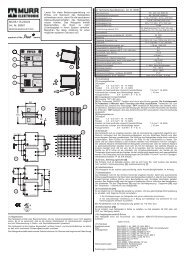
Technische Daten:<br />
Eingangsgrößen: Umgebung:<br />
Eingangsspannung: Lagertemperatur: -40 … +80°C<br />
+24 V DC (SELV/ PELV) Umgebungstemperatur: 0 … +55°C<br />
Restwelligkeit vom Netzteil < 5% für 1-phasiges, Kühlung durch natürliche Konvektion<br />
2% für 3-phasiges Sicherheit:<br />
Arbeitsspannungsbereich Bemessungsisolationsspannung: 50 V<br />
18 … 30 V DC Verschmutzungsgrad 2<br />
Ein-/Ausschaltfrequenz max. 0,5 Hz Überspannungskategorie III<br />
Suppressorschutz 36 V Zusätzlicher Ausgangsschutz:<br />
kein Verpolungsschutz Interne Sicherung 4 A, je Kanal<br />
Betriebssummenstrom (Volllast): 32 A (0 …+20%)<br />
Max. Summenstrom der +24 V Klemmen: 50 A<br />
(UL 248-14, UL File E10480)<br />
Ausgangsgrößen: Vorschriften:<br />
Ausgangsnennspannung: EN 60529: IP20<br />
24 V DC, entsprechend der Eingangsspannung EN 61000-6-2: Störfestigkeit Klasse A<br />
Spannungsabfall bei 4 A pro Lastzweig: EN 61000-6-3: Störaussendung Klasse B<br />
typ. 0,1 V EN 60068-2-6: Schwingprüfung<br />
Einschaltkapazität:<br />
Max. 20 mF*<br />
EN 60068-2-27: Schockprüfung<br />
Interne Absicherung mit Schmelzsicherung: 4 A träge Gewicht: ca. 160 g<br />
Signalisierung: siehe, Anzeigen Abmessungen HxBxT: 90x70x80 mm<br />
*Abhängig von: Bauteiltoleranz, Leitungslänge, verwendetes Netzteil, Laststrom, gewählter Strombereich<br />
Prinzipschaltplan:<br />
ON<br />
Hinweis:<br />
Bitte beachten Sie die Strombelastbarkeit Ihrer Leitung nach Leitungsquerschnitt, Umgebungstemperatur,<br />
Strombelastung sowie der verwendeten Absicherung. Diese <strong>Installationsanleitung</strong> enthält aus<br />
Übersichtlichkeitsgründen nicht alle Detailinformationen zu allen Typen des Produktes und kann auch nicht<br />
jeden erdenkbaren Fall der Aufstellung, des Betriebs oder der Installation berücksichtigen. Weiterführende<br />
Informationen entnehmen Sie bitte aus dem Datenblatt bzw. der Homepage http://www.murrelektronik.com.<br />
Technische Änderungen jederzeit vorbehalten.<br />
© 2009 <strong>Murrelektronik</strong> GmbH, Oppenweiler<br />
Alle Rechte vorbehalten. Jeder Nachdruck, auch auszugsweise, bedarf unserer Genehmigung.<br />
<strong>Murrelektronik</strong> GmbH Postfach 1165 D-71567 Oppenweiler Telefon +49(0)7191/47-0<br />
Falkenstraße 3 D-71570 Oppenweiler Telefax +49(0)7191/47-130<br />
info@murrelektronik.com http://www.murrelektronik.com<br />
1<br />
2<br />
8<br />
8<br />
Technische Änderungen vorbehalten / We reserve the right to change this specification Schutzvermerk ISO 16016 beachten / Refer to protection notice ISO 16016<br />
Vom EDV-System heruntergeladene bzw. ausgedruckte Dokumente besitzen informative n Charakter und unterliegen nicht dem Änderun gsdienst /<br />
Documents downloaded by the EDP system and/or printed out have only an informative character and are not subject to the updating service<br />
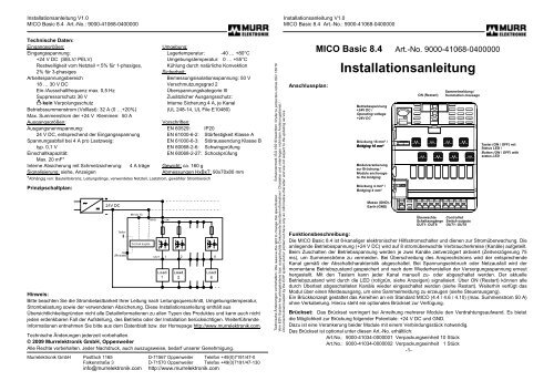
Anschlussplan:<br />
MICO Basic 8.4 Art.-No. 9000-41068-0400000<br />
<strong>Installationsanleitung</strong><br />
Betriebsspannung<br />
+24V DC /<br />
Operating voltage<br />
+24V DC<br />
Brückung 16 mm² /<br />
Bridging 16 mm²<br />
Modulverankerung<br />
zur Brückung /<br />
Module anchorage<br />
to the bridging<br />
Brückung 4 mm² /<br />
Bridging 4 mm²<br />
Masse (GND) /<br />
Earth (GND)<br />
ON (Restart)<br />
Überwachte<br />
Schaltausgänge<br />
OUT1- OUT8<br />
Sammelmeldung /<br />
Summation message<br />
Controlled<br />
Switch outputs<br />
OUT1- OUT8<br />
Taster (ON / OFF) mit<br />
Status LED /<br />
Button (ON / OFF) with<br />
status LED<br />
Funktionsbeschreibung:<br />
Die MICO Basic 8.4 ist 8-kanaliger elektronischer Hilfsstromschalter und dienen zur Stromüberwachung. Die<br />
anliegende Betriebsspannung (+24 V DC) wird auf 8 stromüberwachte Verbraucherkreise (Kanäle) aufgeteilt.<br />
Beim Zuschalten der Betriebsspannung werden je zwei Kanäle zeitverzögert aktiviert (Zeitverzögerung 75<br />
ms), um Summenströme zu vermeiden. Bei Überschreitung des Ansprechstroms wird der entsprechende<br />
Kanal gemäß der Abschaltcharakteristik abgeschaltet. Bei Spannungseinbruch oder Netzausfall wird der<br />
momentane Betriebszustand gespeichert und nach dem Wiederherstellen der Versorgungsspannung erneut<br />
hergestellt. Mit den Tastern kann jeder Kanal manuell zu- oder abgeschaltet werden. Der aktuelle<br />
Betriebszustand wird durch die LED (rot/grün, siehe Anzeigen) signalisiert. Über ON (Restart) können alle<br />
durch Überlast abgeschalteten Kanäle wieder eingeschaltet werden (siehe Restart). Weiterhin verfügt das<br />
Modul über einen Meldeausgang, um eine Sammelmeldung zu erzeugen (siehe Steuerausgang).<br />
Ein Brückkonzept gestattet das Anreihen an ein Standard MICO (4.4 / 4.6 / 4.10) (max. Summenstrom 50 A)<br />
ohne Verkabelung. Hierzu steht ein optionales Brückset zur Verfügung.<br />
Brückset: Das Brückset verringert bei Anreihung mehrerer Module den Verdrahtungsaufwand. Es bietet<br />
die Möglichkeit zur Brückung folgender Potentiale: +24 V DC und GND.<br />
Dazu ist eine Verankerung beider Module mit einem Verbindungsstück notwendig.<br />
Das Brückset ist optional unter diesen Art.-No. erhältlich:<br />
Art.No.: 9000-41034-0000001 Verpackungseinheit 10 Stück<br />
Art.No.: 9000-41034-0000002 Verpackungseinheit 1 Stück<br />
-1-
<strong>Installationsanleitung</strong> V1.0 <strong>Installationsanleitung</strong> V1.0<br />
MICO Basic 8.4 Art.-No.: 9000-41068-0400000 MICO Basic 8.4 Art.-No.: 9000-41068-0400000<br />
Sicherheitshinweise:<br />
Warnung: Der Betrieb des Gerätes ist nur an +24 V Gleichspannung (Schutzkleinspannung) vorgesehen.<br />
Direkter Anschluss dieser Geräte an andere Netze kann zum Tod oder schweren Körperverletzungen, sowie<br />
zu erheblichen Sachschäden führen. Nur entsprechend qualifiziertes Fachpersonal darf an diesem Gerät<br />
oder in dessen Nähe arbeiten. Der einwandfreie und sichere Betrieb dieses Gerätes setzt sachgemäßen<br />
Transport, fachgerechte Lagerung, Aufstellung und Montage voraus.<br />
Achtung:<br />
- Keine metallischen Teile des Gerätes berühren und nicht in das Gerät greifen.<br />
- Bei Servicearbeiten und manuell ausgeschalteten MICO hat der Betreiber dafür Sorge zu tragen,<br />
dass das System gegen unbeabsichtigtes Wiedereinschalten geschützt ist. (gemäß geltender<br />
Vorschriften BGV A3 bzw. EN 50110-1)<br />
- Parallelschaltung mehrerer Lastzweige zur Leistungserhöhung ist nicht zulässig.<br />
- Kaskadenschaltung mehrerer MICO-Module zur Bildung selektiver Abschaltcharakteristik ist<br />
nicht zulässig.<br />
- Die generierte Spannung am Ausgang darf nicht dauerhaft höher als die Eingangsspannung<br />
sein.<br />
Hinweis: Der GND- Anschluss des Gerätes dient lediglich der Versorgung der internen Elektronik. Die 0V<br />
der Verbraucher sind über getrennte Leitungen direkt zur Stromversorgung zu führen.<br />
Die Leiterquerschnitte und Leitungslängen müssen dem eingestellten Strombereich angepasst sein!<br />
Empfehlung: - Strombereich nur bei abgeschaltetem Kanal (LED rot) umstellen.<br />
- GND-Leitung möglichst nah und parallel zur 24 V-Leitungen verlegen.<br />
Installation: Für die Installation sind die einschlägigen DIN/VDE- Bestimmungen oder länderspezifischen<br />
Vorschriften zu beachten. Montage auf Tragschiene TH 35 nach EN 60715. Das Gerät ist aufgrund<br />
betriebsbedingter Erwärmung vertikal so zu montieren, dass die Eingangsklemmen oben sind. Oberhalb und<br />
unterhalb des Gerätes soll mindestens ein Freiraum von je 30 mm eingehalten werden. Der Anschluss der<br />
Versorgungsspannung (+24 VDC) muss gemäß VDE 0100 und VDE 0160 ausgeführt werden und darf nur<br />
an eine Stromversorgung mit „sicherer Trennung“ (SELV/ PELV) entsprechend EN 60950-1 bzw. 61558-2-6<br />
angeschlossen werden.<br />
Lieferzustand: - Kanal ausgeschaltet Lieferumfang: - Modul MICO Basic 8.4<br />
- <strong>Installationsanleitung</strong><br />
- Bezeichnungsschilder<br />
Zubehör: - Brückset: (siehe Brückset) / - Bezeichnungsschilder: Art.No.: 996078<br />
ON-Restart - Eingang: Der ON-Restart – Eingang bietet dem Anwender die Möglichkeit durch Überstrom<br />
abgeschaltete Verbraucherkreise wieder einzuschalten. Indem man an den Eingang ein definiertes Signal<br />
anlegt, min. 1 s. lang „AUS“ 0 V... 5 V DC und min. 20 ms. lang „EIN“ bei 10 V... 30 V DC. Dies gilt nicht<br />
für manuell abgeschaltete Kanäle. Diese können nur am Modul durch den Taster (2) aktiviert werden.<br />
Sammelmeldung: Die Sammelmeldung wird durch einen „active-high“ Meldeausgang (Klemmen 13)<br />
realisiert. Die wird „active-low“, wenn ein Kanal abgeschaltet wird. Dieser Meldeausgang hat die gleichen<br />
Spannungsspegel wie die Eingangsspannung und eignet sich zum Treiben von SPS-Eingängen.<br />
Zulassungen:<br />
-2-<br />
Anschluss- und Klemmenbelegung:<br />
Benutzen Sie nur Kupferdraht für 60/75°C oder äquivalente!<br />
Klemmen Funktion Klemmbereich Bemerkung<br />
Input Anschluss Eingangsspannung +24 V max. 16 mm²<br />
+24 V<br />
bis AWG 6<br />
Input<br />
GND<br />
Abschaltzeit / turn-off time in ms<br />
Anschluss GND zur Versorgung der<br />
internen Elektronik<br />
Output Ausgänge des MICO zum Anschluss<br />
OUT 1…4 an den Verbraucherkreis<br />
1000000<br />
100000<br />
10000<br />
1000<br />
100<br />
10<br />
1<br />
4,0A<br />
Strom / current in A<br />
max. 4 mm²<br />
bis AWG 12<br />
min.0,5 mm²<br />
AWG 20<br />
max. 4 mm²<br />
AWG 12<br />
max. 2,5 mm²<br />
AWG 12<br />
ON Ferneinschalten (außer Funktion bei<br />
manuell abgeschalteten Kanal (rot))<br />
13 Sammelmeldeausgang max. 2,5 mm²<br />
bis AWG 12<br />
Anzeigen:<br />
LED-Status Kanalzustand Bedeutung<br />
grün eingeschaltet - Funktion OK<br />
rot ausgeschaltet - manuell abgeschaltet<br />
Hinweis: Die 0V der Verbraucher<br />
sind über getrennte Leitungen direkt<br />
zur Stromversorgung zu führen!!<br />
grün blinkend Grenzbereich - Belastung über 90% von Ansprechstrom<br />
rot blinkend 1 Hz abgeschaltet - Überstrom<br />
rot schnell blinkend 5 Hz defekt - Interner Fehler<br />
Abschaltcharakteristik:<br />
Jeder Strombereich verfügt über eine separate Abschaltcharakteristik mit einer Grundgenauigkeit von<br />
0...+20% – siehe Diagramm. Die Abschaltzeit beim Kurzschluss beträgt 5 ms.<br />
1 10<br />
-3-<br />
100
Installation instructions V1.0 <strong>Murrelektronik</strong> Intelligent Current Operator Installation instructions V1.0 <strong>Murrelektronik</strong> Intelligent Current Operator<br />
MICO Basic 8.4 Art.-No.: 9000-41068-0400000 MICO Basic 8.4 Art.-No.: 9000-41068-0400000<br />
Technical data:<br />
Input values: Signalling: See “Displays“<br />
Input voltage: Environment:<br />
+24 V DC (SELV/ PELV) Storing temperature: -40°C to +80°C<br />
Residual ripple of power supply Environmental temperature: 0 to +55°C<br />
< 5% for one-phase, 2% for three-phase Cooling by natural convection<br />
Range of working voltage Safety:<br />
18-30 V DC Rated insulation voltage: 50V<br />
Frequency of power ON/OFF max 0,5Hz degree of pollution: 2<br />
Suppression protector 36 V Classification of over-voltage III<br />
No reverse polarity protection Additional output protection:<br />
Total operating current: 32 A (0 to +20%) 4 A fuse for each channel internal<br />
(UL 248-14, UL File E10480).<br />
Maximum summation current of (+24 V) Regulations:<br />
terminals: 50 A EN 60529: Protective system - IP20<br />
Output values: EN 61000-6-2:<br />
Nominal output voltage: Immunity to interference class A<br />
24V DC, corresponding to the input voltage EN 61000-6-3:<br />
Voltage drop at 4 A per each load branch: Interference emission class B<br />
typical 0.1 V EN 60068-2-6: Oscillating test<br />
Turn ON capacity: EN 60068-2-27: Shock test<br />
max. 20 mF* Weight: ca. 160 g<br />
Internal fuse: 4 A delay fuse for each channel Measurements LxWxD: 90x70x80 mm<br />
* Dependent on: component tolerance, conduit length, used power supply, load current, selected current range<br />
Schematic circuit diagram:<br />
ON<br />
Notice:<br />
Please pay attention to the wire capability in relationship of its cross section, ambient temperature, current as<br />
well as the used protection.For lucid reasons this installation instructions does not contain detailed<br />
information to all types of this product and may not consider each fictitious case of erection, operation or<br />
installation. Continuing information may be taken from the data sheet or from our homepage in the internet<br />
http://www.murrelektronik.com.<br />
Technical alterations are reserved at any time.<br />
© 2009 <strong>Murrelektronik</strong> GmbH, Oppenweiler<br />
All rights reserved. Each reprint, even in parts, requires our written consent.<br />
<strong>Murrelektronik</strong> GmbH P.O. Box 1165 D-71567 Oppenweiler Telefon +49(0)7191/47-0<br />
Falkenstrasse 3 D-71570 Oppenweiler Telefax +49(0)7191/47-130<br />
info@murrelektronik.com http://www.murrelektronik.com<br />
1<br />
2<br />
8<br />
8<br />
Technische Änderungen vorbehalten / We reserve the right to change this specification Schutzvermerk ISO 16016 beachten / Refer to protection notice ISO 16016<br />
Vom EDV-System heruntergeladene bzw. ausgedruckte Dokumente besitzen informative n Charakter und unterliegen nicht dem Änderun gsdienst /<br />
Documents downloaded by the EDP system and/or printed out have only an informative character and are not subject to the updating service<br />
Wiring diagram:<br />
MICO Basic 8.4 Art.-No. 9000-41068-0400000<br />
Functional description:<br />
Installation instructions<br />
Betriebsspannung<br />
+24V DC /<br />
Operating voltage<br />
+24V DC<br />
Brückung 16 mm² /<br />
Bridging 16 mm²<br />
Modulverankerung<br />
zur Brückung /<br />
Module anchorage<br />
to the bridging<br />
Brückung 4 mm² /<br />
Bridging 4 mm²<br />
Masse (GND) /<br />
Earth (GND)<br />
ON (Restart)<br />
Überwachte<br />
Schaltausgänge<br />
OUT1- OUT8<br />
Sammelmeldung /<br />
Summation message<br />
Controlled<br />
Switch outputs<br />
OUT1- OUT8<br />
Taster (ON / OFF) mit<br />
Status LED /<br />
Button (ON / OFF) with<br />
status LED<br />
MICO Basic 8.4 is a 8-channel electronic auxiliary circuit switch and serves as current monitoring. The<br />
operating voltage (+24 V DC /) supplies the 8 current monitored load circuits (channels). By applying the<br />
operating voltage two channels each cascade time are activated (cascade time-delay = 75 ms) to avoid<br />
overload current. When exceeding the operating current the corresponding channel will be disconnected<br />
pursuant to the disconnecting characteristic. In the event of voltage dip or power failure the current operating<br />
condition will be saved and reestablished after the recovery of the supply voltage. Each channel may be<br />
manually connected or disconnected through the button. The current operating condition is signalled by the<br />
LED – (red/green, see displays). All channels disconnected due to overload may be activated through ON<br />
(restart) – see restart. In addition, the module is provided with a message output to give a summation<br />
message (see control output). A bridging concept permits the lining-up on a standard MICO (4.4 / 4.6 / 4.10)<br />
(maximum operating current 50A) without wiring. For this purpose a bridging set is available as an option.<br />
Bridging set: The bridging set minimises the efforts of wiring if multiple modules are joined together.<br />
It offers the possibility of bridging the following potentials: +24 V DC and GND.<br />
A connecting piece is necessary to anchor both modules. The bridging set is optionally available under:<br />
item no.: 9000-41034-0000001 (packing unit 10 pieces)<br />
item no.: 9000-41034-0000002 (packing unit 1 pieces)<br />
-1-
Installation instructions V1.0 <strong>Murrelektronik</strong> Intelligent Current Operator Installation instructions V1.0 <strong>Murrelektronik</strong> Intelligent Current Operator<br />
MICO Basic 8.4 Art.-No.: 9000-41068-0400000 MICO Basic 8.4 Art.-No.: 9000-41068-0400000<br />
Safety instructions:<br />
Warning: This equipment is only suitable for the operation on +24V DC (protection low voltage). The direct<br />
connection of this equipment may cause death, severe bodily injuries and considerable property<br />
damage.Only competent and qualified personnel may work on this equipment or in its proximity. The perfect<br />
and safe operation of this equipment requires the appropriate transportation, professional storage, erection<br />
and installation.<br />
Attention:<br />
- Prevent touching of metal parts or reaching into this equipment.<br />
- During service work when manually disconnecting MICO, the operating company shall ensure that the<br />
system is protected against unintended reconnection (according to the currently applicable provisions BGV<br />
A3 (Trade Association Ordinance) or. EN 50110-1).<br />
- Parallel switching of multiple load branches for increase of power is not permitted.<br />
- Series connection of several MICO module to produce selective switch-off-characteristic is<br />
not allowed.<br />
- A generated voltage at output is not allowed to be durably higher than the input voltage.<br />
Notice: The GND connection of the equipment merely serves to supply the internal electronics. The 0<br />
voltage of the consumer shall be conducted directly to the power supply through separate lines.<br />
The conductor cross-sections and line lengths must be adapted to the adjusted current range.<br />
Recommendation: - Adjust the current range only if the channel is disconnected (red LED).<br />
- Lay GND wire as near and parallel as possible to the 24V lines.<br />
Installation: For the installation the pertinent DIN/VDE regulations or country-specific rules must be<br />
complied with. Assemble on support bar TH 35 pursuant to EN 60715. Due to operation-related heating the<br />
equipment must be assembled vertically so that the input terminals are on top. A free space of 30 mm above<br />
and below the equipment should be complied with. The connection of the supply voltage (24V DC) must be<br />
performed in accordance with VDE 100 and VDE 0160 and shall only be connected to a power supply with<br />
“safe separation“ (SELV/PELV) corresponding to EN 60950-1 or 61558-2-6.<br />
Condition at delivery: Scope of delivery: - Module MICO Basic 8.4<br />
- Installation instructions<br />
- Channel disconnected - Designation labels<br />
Accessories: - Bridging set: (see bridging set) / - Designation labels: Art.No.: 996078<br />
ON-Restart - input: The ON-Restart – input provides the user with the possibility of reconnecting load<br />
circuits disconnected by excess current by placing a defined signal at the input, e.g. 0V... 5V for “OFF“ min.<br />
1s long and 10V - 30V for “ON“ min. 20ms long. This does not apply to manually disconnected channels.<br />
They may only be activated through the button (2) at the module.<br />
Summation message: The summary output message is an active-high signal (terminals 13). It becomes<br />
low if a channel has been disconnected. The message output has same voltage level as the input voltage<br />
and is suitable to drive SPS inputs.<br />
Approvals:<br />
-2-<br />
Pin connections and terminal assignment:<br />
Use 60/75°C copper conductors only or equivalent.<br />
Terminals Function Terminal range Remarks<br />
Input +24V Connection Input voltage +24V Max. 16 mm²<br />
to AWG 6<br />
Input GND Connection GND to supply the Max. 2.5 mm²<br />
internal electronic<br />
to AWG 12<br />
Output<br />
OUT 1…8<br />
MICO outputs to be connected<br />
with the load circuit<br />
min.0,5 mm²<br />
to AWG20<br />
max. 4 mm²<br />
to AWG 12<br />
ON Remote activation (except Max. 2.5 mm²<br />
function at manually to AWG 12<br />
13<br />
Displays:<br />
disconnected channel [red])<br />
Summation message contact Max. 2.5 mm²<br />
to AWG 12<br />
Display State Indication<br />
green connected - Function OK<br />
Notice: The 0V of the consumer must<br />
lead directly to the voltage supply<br />
through separate lines!<br />
red disconnected - Manually disconnected<br />
green flashing threshold - Load above 90% of operating current<br />
red flashing 1 Hz disconnected - Over current<br />
red quickly flashing 5 Hz defect - Internal fault<br />
Disconnecting characteristic:<br />
Each current range is provided a separate disconnecting characteristic with a basic accuracy of 0...+20% –<br />
see diagram. The disconnecting time at short-circuit amounts to max. 5 m/s.<br />
Abschaltzeit / turn-off time in ms<br />
1000000<br />
100000<br />
10000<br />
1000<br />
100<br />
10<br />
1<br />
4,0A<br />
Strom / current<br />
in A<br />
1 10 100<br />
-3-