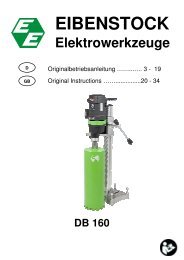
ETN 130- 3P deu. eng. - Eibenstock
ETN 130- 3P deu. eng. - Eibenstock
ETN 130- 3P deu. eng. - Eibenstock
Sie wollen auch ein ePaper? Erhöhen Sie die Reichweite Ihrer Titel.
YUMPU macht aus Druck-PDFs automatisch weboptimierte ePaper, die Google liebt.
D<br />
GB<br />
EIBENSTOCK<br />
Elektrowerkzeuge<br />
Originalbetriebsanleitung..……...…. .2 - 19<br />
Original Instructions …..…...............20 - 36<br />
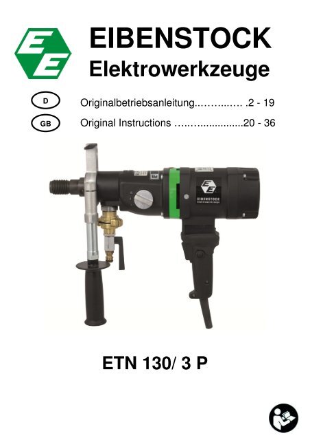
<strong>ETN</strong> <strong>130</strong>/ 3 P
Wichtige Sicherheitshinweise<br />
DEUTSCH<br />
Wichtige Anweisungen und Warnhinweise sind mittels Symbolen auf der<br />
Maschine dargestellt:<br />
Vor Inbetriebnahme der Maschine<br />
Bedienungsanleitung lesen.<br />
Arbeiten Sie konzentriert und lassen Sie Sorgfalt<br />
walten. Halten Sie Ihren Arbeitsplatz sauber und<br />
vermeiden Sie Gefahrensituationen.<br />
Vorkehrungen zum Schutz des Bedieners treffen.<br />
Zu Ihrem Schutz sollten Sie folgende Schutzmaßnahmen treffen<br />
Gehörschutz benutzen<br />
Augenschutz benutzen<br />
Schutzhelm benutzen<br />
Schutzhandschuhe benutzen<br />
Schutzschuhe benutzen<br />
Warnung vor gefährlicher elektrischer Spannung<br />
Warnung vor heißer Oberfläche<br />
Maschine, Bohrkrone und Bohrständer sind schwer<br />
– Vorsicht Quetschgefahr<br />
Reiß- bzw. Schneidgefahr<br />
2
Gerätekennwerte<br />
Diamant – Kernbohrmaschine <strong>ETN</strong> <strong>130</strong> / 3 P<br />
Nennspannung: 230 V ~ 110 V ~<br />
Leistungsaufnahme: 1800 W 1700 W<br />
Nennstrom: 8,3 A 16 A<br />
Bestellnummer 03A31 03A32<br />
Frequenz: 40-60 Hz<br />
Max. Bohrdurchmesser<br />
In Beton (Nassschnitt): 152 mm<br />
Im Mauerwerk (Trockenschnitt): 200 mm<br />
Werkzeugaufnahme: 1 ¼“ UNC<br />
Schutzklasse: I<br />
Schutzgrad: IP 20<br />
Gewicht: ca. 7,3 kg<br />
Funkentstörung nach: EN 55014 und EN 61000<br />
Gang Leerlaufdrehzahl Lastdrehzahl Max. Bohrdurchmesser<br />
Beton Mauerwerk<br />
I 900 min -1 600 min -1 152 mm 200 mm<br />
II 2000 min -1 <strong>130</strong>0 min -1 70 mm<br />
III 4000 min -1 2800 min -1 40 mm<br />
lieferbares Sonderzubehör:<br />
Artikel Bestell Nr.<br />
Diamantbohrständer Direktaufnahme BST 152/60 09622<br />
Zubehörset für Bohrständer 35720<br />
Diamantbohrkronen trocken Ø 52 – 202 mm<br />
Diamantbohrkronen nass Ø 32 – 152 mm<br />
Kupferringe zum leichten Lösen der Bohrkrone 35450<br />
Bohrkronenverlängerungen<br />
Zentrierstange 36391<br />
Schnellspannsäule 35730<br />
Wasserdruckgefäß 10l Metall 35810<br />
Naß/ Trockensauger DSS 25 A 09915<br />
Vakuumpumpe 09201<br />
Vakuumschlauch 35855<br />
Wassersammelring WR 152 3587A<br />
3
Lieferumfang<br />
Diamantkernbohrgerät mit im Kabel integriertem PRCD- Schutzschalter,<br />
Nassanschluss mit Kugelhahn und GARDENA– Stecknippel,<br />
Übergangsstück für Staubsaugeranschluss (Ø 35 mm) und<br />
Bedienungsanleitung im Transportkoffer.<br />
Bestimmungsgemäßer Gebrauch<br />
Die Diamant- Kernbohrmaschine <strong>ETN</strong> <strong>130</strong>/3 P ist nur für den<br />
professionellen Einsatz bestimmt und darf nur von unterwiesenen<br />
Personen bedient werden.<br />
Sie kann sowohl in einem dafür geeigneten Diamantbohrständer als auch<br />
Freihand betrieben werden. In Verbindung mit den entsprechenden<br />
Diamantbohrkronen ist die Maschine zum Bohren von Beton und Stein im<br />
Nassschnitt sowie Ziegel, Kalksandstein und Porenbeton im Trockenschnitt<br />
bestimmt.<br />
Für Bohrungen im Nassschnitt mit Durchmesser über 70 mm und<br />
Verwendung des ersten Ganges ist der Einsatz eines geeigneten<br />
Bohrständers zwingend erforderlich.<br />
Freihandbohren im Nassschnitt im ersten Gang ist verboten! Auftretendes<br />
Gegendrehmoment kann beim unachtsamen Gebrauch zu einer<br />
Gefährdung des Bedieners führen!<br />
Sicherheitshinweise<br />
Gefahrloses Arbeiten mit dem Gerät ist nur möglich, wenn<br />
Sie die Bedienungsanleitung und die Sicherheitshinweise<br />
vollständig lesen und die darin enthaltenen Anweisungen<br />
strikt befolgen.<br />
Zusätzlich müssen die allgemeinen Sicherheitshinweise im<br />
beigelegten Heft befolgt werden. Lassen Sie sich vor dem<br />
ersten Gebrauch praktisch einweisen.<br />
Wird bei der Arbeit die Anschlussleitung beschädigt oder<br />
durchtrennt, diese nicht berühren, sondern sofort den<br />
Netzstecker ziehen. Gerät niemals mit beschädigter<br />
Anschlussleitung betreiben.<br />
4
Überprüfen Sie vor dem Bohren in Decken und Wänden die<br />
Bohrstelle auf verdeckt liegende Strom-, Gas- und<br />
Wasserleitungen.<br />
Überprüfen Sie den Arbeitsbereich, z.B. mit einem<br />
Metallortungsgerät.<br />
Konsultieren Sie den verantwortlichen Statiker vor Beginn ihrer<br />
Arbeit zur Festlegung der genauen Position der Bohrung.<br />
Sichern Sie bei Durchbohrungen durch Decken den Bereich von<br />
unten ab, da der Bohrkern nach unten herausfallen kann.<br />
Achten Sie darauf, dass die Maschine keinem direkten Regen<br />
ausgesetzt ist.<br />
� Arbeiten Sie nicht in explosionsgefährdeter Umgebung.<br />
� Arbeiten Sie nicht auf Leitern.<br />
� Asbesthaltige Materialien dürfen nicht bearbeitet werden.<br />
� Tragen Sie das Gerät niemals am Kabel und überprüfen Sie vor<br />
jeder Benutzung Gerät, Kabel und Stecker. Lassen Sie Schäden<br />
nur von einem Fachmann beseitigen. Stecker nur bei<br />
ausgeschalteter Maschine in die Steckdose stecken.<br />
� Manipulationen am Gerät sind nicht erlaubt.<br />
� Ziehen Sie den Netzstecker, und überprüfen Sie, dass der Schalter<br />
ausgeschaltet ist, wenn die Kernbohrmaschine unbeaufsichtigt<br />
bleibt, z.B. bei Auf- und Abbauarbeiten, bei Spannungsausfall,<br />
beim Einsetzen bzw. bei der Montage eines Zubehörteiles.<br />
� Schalten Sie die Maschine ab, wenn Sie aus irgendeinem Grund<br />
stehen bleibt. Sie vermeiden damit das plötzliche Anlaufen im<br />
unbeaufsichtigten Zustand.<br />
� Benutzen Sie das Gerät nicht, wenn ein Teil des Gehäuses defekt<br />
ist, bzw. bei Beschädigungen an Schalter, Zuleitung oder Stecker.<br />
� Führen Sie beim Arbeiten das Netz-, das Verlängerungskabel und<br />
den Absaugschlauch immer nach hinten vom Gerät weg.<br />
� Elektrowerkzeuge müssen in regelmäßigen Abständen einer<br />
Sichtprüfung durch den Fachmann unterzogen werden.<br />
� Beim Betreiben des Kernbohrgerätes darf in keiner Gebrauchslage<br />
Kühlwasser in den Motor und die elektrischen Einbauteile<br />
eindringen.<br />
� Tritt Wasser aus der Überlaufbohrung am Getriebehals aus,<br />
brechen Sie die Arbeiten ab und lassen Sie das Kernbohrgerät in<br />
einer autorisierten Fachwerkstatt reparieren.<br />
� Überkopfbohrungen nur mit geeigneten Schutzvorkehrungen<br />
(Wasserauffangvorrichtung) durchführen.<br />
5
� Schalten Sie nach einer Unterbrechung Ihrer Arbeit die<br />
Kernbohrmaschine nur dann ein, nachdem Sie sich davon<br />
überzeugt haben, dass sich die Bohrkrone frei drehen lässt.<br />
� Das Gerät darf nur zweihandgeführt oder am Bohrständer<br />
eingesetzt werden.<br />
� Halten Sie die Handgriffe trocken, sauber und frei von Öl und Fett.<br />
� Nicht in rotierende Teile fassen.<br />
� Personen unter 16 Jahren dürfen das Gerät nicht benutzen.<br />
� Der Benutzer und die sich in der Nähe aufhaltenden Personen<br />
müssen während der Benutzung des Gerätes eine geeignete<br />
Schutzbrille, Schutzhelm, Gehörschutz, Schutzhandschuhe und<br />
Sicherheitsschuhe benutzen.<br />
� Während des Handbetriebes Gerät immer mit beiden Händen<br />
halten und einen sicheren Stand einnehmen. Beachten Sie das<br />
Reaktionsdrehmoment der Maschine im Blockierfall.<br />
� Arbeiten Sie stets konzentriert. Gehen Sie überlegt vor und<br />
verwenden Sie das Gerät nicht, wenn Sie unkonzentriert sind.<br />
� Bei Trockenbohrungen im Handbetrieb zwischen 100 und 200<br />
mm sind mit besonderer Umsicht zu arbeiten!<br />
Weitere Sicherheitshinweise entnehmen Sie bitte der Anlage!<br />
Elektrischer Anschluss<br />
Die <strong>ETN</strong> <strong>130</strong>/3 P ist in Schutzklasse I ausgeführt. Zum Schutz des<br />
Bedieners darf die Maschine nur über eine Fehlerstromschutzeinrichtung<br />
betrieben werden. Das Gerät wird deshalb standardmäßig mit integriertem<br />
PRCD – Schutzschalter zum Einsatz an einer Schutzkontaktsteckdose<br />
geliefert.<br />
! Achtung!<br />
• Der PRCD – Schutzschalter darf nicht im Wasser liegen.<br />
• PRCD – Schutzschalter nicht zum Ein- und Ausschalten<br />
der Maschine verwenden.<br />
• Vor Arbeitsbeginn die ordnungsgemäße Funktion durch<br />
Drücken der TEST – Taste überprüfen.<br />
Verwenden Sie nur 3-adriges Verlängerungskabel mit Schutzleiter und<br />
ausreichendem Querschnitt (siehe Tabelle). Ein zu schwacher Querschnitt<br />
kann zur Fehlfunktion der Maschine führen.<br />
6
Empfohlene Mindestquerschnitte und maximale Kabellängen<br />
Netzspannung Querschnitt in mm²<br />
1,5 2,5<br />
110V 20 m 40 m<br />
230V 50 m 80 m<br />
Prüfen Sie vor Inbetriebnahme die Übereinstimmung der Netzspannung<br />
und -frequenz mit den auf dem Typenschild angegebenen Daten.<br />
Spannungsabweichungen von + 6 % und – 10 % sind zulässig.<br />
Die Maschine verfügt über eine Anlaufstrombegrenzung die verhindert,<br />
dass flinke Sicherungsautomaten unbeabsichtigt auslösen.<br />
Zusatzhandgriff<br />
Im Handbetrieb darf die <strong>ETN</strong> <strong>130</strong>/3 P nur in Verbindung<br />
mit dem beiliegenden Zusatzhandgriff betrieben werden.<br />
Dieser wird von vorn auf den Getriebehals aufgesteckt<br />
und durch Drehen des Handgriffes in Pfeilrichtung fest<br />
angezogen.<br />
Wasseranschluss<br />
Setzen Sie den Adapter mit dem Kugelhahn auf den<br />
Anschluss der Maschine auf und drehen Sie ihn in<br />
Pfeilrichtung gegen den Anschlag. Schließen Sie die<br />
Maschine über das Stecknippel an die<br />
Wasserversorgung oder ein Wasserdruckgefäß an.<br />
Achtung! Der maximale Wasserdruck sollte 6 bar<br />
nicht überschreiten. Bei höherem Wasserdruck<br />
ist ein Druckminderer bauseits zu verwenden.<br />
Als Verbindungsstück zur Maschine verwenden Sie bitte eine handelsübliche<br />
GARDENA– Schlauchkupplung.<br />
Verwenden Sie nur sauberes Leitungswasser.<br />
Tritt Wasser aus der Überlaufbohrung am Getriebehals aus, brechen<br />
Sie die Arbeiten ab und lassen Sie das Kernbohrgerät in einer autorisierten<br />
Fachwerkstatt reparieren.<br />
7
1.Gang<br />
0 - 600 min -1<br />
2. Gang<br />
0 – <strong>130</strong>0 min -1<br />
3. Gang<br />
0 – 2800 min -1<br />
Staubabsaugung<br />
Beim Arbeiten entstehender Staub ist<br />
gesundheitsschädlich. Bei Trockenbohrungen ist<br />
deshalb ein Staubsauger zu verwenden und eine<br />
Staubschutzmaske zu tragen. Setzen Sie den Adapter<br />
für die Staubabsaugung auf den Anschluss der<br />
Maschine und drehen Sie ihn in Pfeilrichtung gegen<br />
den Anschlag. Der passende Nass-Trocken-Sauger<br />
DSS 25 A ist als Zubehör erhältlich. Die Verwendung<br />
einer Absaugung ist ebenfalls Voraussetzung für eine<br />
optimale Schnittleistung der Bohrkrone (Luftkühlung).<br />
Getriebeumschaltung<br />
Die <strong>ETN</strong> <strong>130</strong>/3 P besitzt ein 3-Gang<br />
Ölbadgetriebe. Passen Sie die Drehzahl dem<br />
Bohrdurchmesser an. Drehen Sie den<br />
Getriebeschalter in den nächst höheren oder<br />
nächst niedrigerem Gang.<br />
Lässt sich die Maschine nicht schalten, ist<br />
durch leichtes Verdrehen der Arbeitsspindel der<br />
Schaltvorgang zu unterstützen.<br />
Kurzes Ein- und Ausschalten kann die<br />
Gangwahl ebenso erleichtern.<br />
Warnung!<br />
!<br />
• Nie mit Gewalt und nur im Auslauf der Maschine<br />
umschalten!<br />
• Verwenden Sie zum Umschalten keine Werkzeuge wie z.B.<br />
Zange oder Hammer!<br />
Durchmesser mm Gang<br />
Handbetrieb<br />
Nass-Schnitt 41 – 71 2<br />
12 – 41 3<br />
Trocken-Schnitt 121 – 201 1<br />
61 – 111 2<br />
Ständerbetrieb<br />
12 – 61 3<br />
Nass-Schnitt 81 – 152 1<br />
41 – 71 2<br />
12 – 41 3<br />
8
Bohrkronenwechsel<br />
Vorsicht!<br />
Das Werkzeug kann durch den Einsatz oder durch Schärfen heiß<br />
werden. Sie können sich die Hände verbrennen oder sich an den<br />
Segmenten schneiden bzw. reißen.<br />
Benutzen Sie für den Werkzeugwechsel deshalb immer<br />
Arbeitsschutzhandschuhe.<br />
Die Bohrspindel hat Rechtsgewinde.<br />
Verwenden Sie als Gegenhalter immer einen Maulschlüssel SW 32, der an<br />
der Bohrspindel angesetzt wird.<br />
Lösen Sie die Bohrkrone niemals mit (Hammer-) Schlägen, da so die<br />
Bohrkrone und die Kernbohrmaschine beschädigt werden.<br />
Etwas wasserfestes Fett, aufgetragen auf dem Bohrspindelgewinde, oder<br />
ein Kupferring zwischen Spindel und Bohrkrone erleichtern das Lösen der<br />
Bohrkrone.<br />
Momentschaltung<br />
Ein-/ Ausschalten<br />
Einschalten: Ein-Aus-Schalter drücken<br />
Ausschalten: Ein-Aus-Schalter loslassen<br />
Dauerschaltung<br />
Einschalten: Ein-Aus-Schalter drücken und in gedrücktem Zustand mit<br />
Feststellknopf arretieren<br />
Ausschalten: Ein-Aus-Schalter erneut drücken und wieder loslassen<br />
Achtung!<br />
!<br />
Benutzen Sie den Feststellknopf nur im Ständerbetrieb. Die<br />
Anwendung im Handbetrieb ist untersagt.<br />
Bei jedem maschinell bedingten Stillstand oder einer<br />
Unterbrechung der Stromversorgung ist der Feststellknopf<br />
sofort durch Drücken des Ein-Aus-Schalters zu lösen.<br />
Wird der Schalter nicht gelöst, kann die Maschine beim<br />
Betätigen des PRCD- Schutzschalters unbeabsichtigt<br />
wieder anlaufen, was eine Gefährdung darstellt.<br />
9
Trockenschnitt<br />
Bohren - handgeführt<br />
Montieren Sie den entsprechenden Adapter zur Staubabsaugung.<br />
(siehe Abb. Seite 8)<br />
Setzen Sie die Zentrierspitze so ein, dass die<br />
Aussparungen der Zentrierspitze in den Mitnehmern<br />
der Arbeitsspindel einrasten.<br />
Schrauben Sie die entsprechende Trockenbohrkrone auf die<br />
Arbeitsspindel.<br />
Überprüfen Sie die korrekte Gangauswahl. Betätigen Sie den<br />
Ein/Ausschalter und bohren Sie soweit, bis sich die Segmente ca.5 mm in<br />
das zu bohrende Material eingearbeitet haben. Entfernen Sie die<br />
Zentrierspitze. Setzen Sie die Bohrkrone in die vorhandene Rille und<br />
beenden Sie die Bohrung.<br />
Nassschnitt<br />
Wir empfehlen im Nassbetrieb den Einsatz der Anbohrhilfe mit<br />
Wasserabsaugung (Bestellnr.35847).<br />
Für „Überkopfbohrungen“ ist die Verwendung der Absaugung<br />
zwingend vorgeschrieben.<br />
Setzen Sie die Gasdruckfeder mit dem<br />
Wassersammelring und dem zum<br />
Bohrkronendurchmesser passenden Führungsring in<br />
die Spannschelle ein. Verschieben Sie die<br />
Gasdruckfeder so weit, bis die Segmente der Krone<br />
vom Wassersammelring verdeckt sind. Ziehen Sie<br />
die Flügelschraube fest.<br />
Achten Sie beim "Überkopfbohren" darauf, dass Sie<br />
die Wasserzufuhr erst öffnen, nachdem Sie den<br />
Sauger angeschaltet und die Absaugung an der<br />
Wand bzw. Decke angesetzt haben.<br />
10
Öffnen Sie den Kugelhahn und schalten Sie die Maschine an.<br />
Halten Sie die Maschine fest in beiden Händen. Setzen Sie die Maschine<br />
leicht geneigt an. Nachdem sich die Bohrkrone in die Oberfläche<br />
eingearbeitet hat (ca. 1/8 – 1/4 des Kreisumfangs) bringen Sie die<br />
Maschine in den 90° Winkel und setzen Sie die Bohrung fort.<br />
Achten Sie beim Bohren besonders darauf, dass die Bohrkrone nicht<br />
verkantet.<br />
Passen Sie den Vorschub dem Kronendurchmesser und der Leistung der<br />
Maschine an. Achten Sie auf die Leuchtdiode im Griff.<br />
Leuchtet diese rot ist der Anpressdruck zu verringern.<br />
Sollte das Bohrkrone klemmen, versuchen sie nicht, dieses durch Ein- und<br />
Ausschalten der Maschine zu lösen. Dies führt zum vorzeitigen Verschleiß<br />
der Sicherheitsrutschkupplung. Schalten Sie die Maschine sofort ab und<br />
lösen Sie die Bohrkrone durch Rechts- und Linksdrehen mit einem<br />
passenden Maulschlüssel. Ziehen Sie dabei die Maschine vorsichtig aus<br />
dem Bohrloch.<br />
Bohren - ständergeführt<br />
Befestigung des Bohrständers durch Vakuum am Fußboden<br />
Verwenden Sie die Vakuumbefestigung nicht an der Wand und<br />
Überkopf!<br />
Für eine Unterdruck-Anbringung darf die zu bohrende Fläche nicht<br />
porös und muss eben und rissfrei sein.<br />
Ist das nicht der Fall, kann diese Art der Anbringung nicht verwendet<br />
werden. Für die Vakuum-Anbringung benötigen Sie Vakuumpumpe, -platte<br />
und -schlauch (siehe Abbildung). Diese sind auf Anfrage erhältlich.<br />
Montieren Sie den Bohrständer auf der Vakuumplatte. Verbinden Sie nun<br />
die Vakuumpumpe und die Vakuumplatte mit Hilfe des Vakuumschlauchs.<br />
Bringen Sie den Bohrständer in die richtige Position und schalten Sie die<br />
Pumpe ein.<br />
Überprüfen Sie, ob alle vier Nivellierschrauben in der Fußplatte ganz<br />
zurück gedreht sind und ein Unterdruck von mind. –0,8 bar erreicht wird.<br />
11
Durch drücken des Ventilknopfes im Griff kann der Bohrständer entlastet<br />
und nachjustiert werden.<br />
Die Vakuumpumpe muss während der gesamten Arbeitszeit<br />
weiterlaufen und ist so zu platzieren, dass sie das Manometer<br />
Einsehen können.<br />
Überprüfen Sie unbedingt den festen Sitz bevor Sie mit dem Bohren<br />
beginnen!<br />
Befestigung durch Dübel in Beton<br />
Für Mauerwerk sind Rawl-<br />
Dübel zu verwenden.<br />
� Zeichnen Sie sich die Position der<br />
Befestigungsbohrung auf der zu bohrenden<br />
Fläche an.<br />
� Bohren Sie ein Loch (Ø 15) 50 mm<br />
tief (A), in das der Dübel M12 (B) eingesetzt<br />
werden soll; setzen Sie den Dübel ein und<br />
spreizen Sie ihn mit dem Dübelsetzwerkzeug<br />
(C)auf.<br />
� Schrauben Sie die Schnellspannschraube (D) in<br />
den Dübel ein.<br />
� Setzen Sie den Ständer auf.<br />
� Fixieren Sie die Unterlegscheibe (E) und<br />
schließlich die Befestigungsmutter (F) auf der<br />
Schnellspannschraube (D).<br />
� Ziehen Sie die Mutter (F) mit einem Schlüssel<br />
SW 27 fest.<br />
� Vor und nach dem Festziehen der Mutter (F)<br />
sind die 4 Stellschrauben zur Anpassung an den<br />
Untergrund entsprechend zu verstellen.<br />
Unbedingt prüfen, ob der<br />
Ständer fest montiert ist.<br />
12
Befestigung durch Schnellspannsäule<br />
Um den Bohrständer mittels der Schnellspannsäule Verstreben zu<br />
können, muss der Abstand zur gegenüberliegenden Wand zwischen<br />
1,7 m und 3 m betragen.<br />
H<br />
G<br />
Positionieren Sie den Bohrständer. Setzen Sie die<br />
Schnellspannsäule so dicht wie möglich hinter der Säule<br />
auf dem Ständerfuß auf. Fixieren Sie den Bohrständer<br />
durch Drehen der Kurbel (G) im Uhrzeigersinn. Sichern<br />
Sie die Einstellung mit dem dazugehörigen Bolzen (H).<br />
Achtung! Es ist wichtig, dass der Bohrständer fest mit dem<br />
Untergrund verbunden ist. Nicht korrekt befestigte Bohrständer<br />
können zur Verletzung des Bedieners und Beschädigung der<br />
Bohreinheit führen. Bewegungen während des Bohrens verursachen<br />
ein Schlagen der Bohrkrone gegen die Bohrungswand, was zum<br />
Ausbrechen der Segmente führen kann. Die Bohrkrone kann sich<br />
ebenso im Bohrloch verkanten, was wiederum Schäden an dieser<br />
verursacht.<br />
Befestigung der Kernbohrmaschine<br />
Vorsicht beim Einsetzen der Maschine,<br />
Quetschgefahr!<br />
Tragen Sie Schutzhandschuhe!<br />
� Fahren Sie den Maschinenhalter (2)<br />
soweit nach oben bis der Arretierbolzen<br />
(5) in der Säule einrastet.<br />
� Entfernen Sie die beiden Innensechskantschrauben<br />
M8 (3)und nehmen Sie<br />
die Spannschelle (4) ab.<br />
� Setzen Sie das Kernbohrgerät auf den<br />
Schlitten und schließen Sie die<br />
Spannschelle (4) mit den<br />
Innensechskantschrauben (3).<br />
13
Bohrkronen<br />
Diamantbohrkronen mit einem 1 ¼" UNC Inn<strong>eng</strong>ewinde können direkt auf<br />
die Arbeitsspindel geschraubt werden.<br />
Für Bohrkronen mit Auß<strong>eng</strong>ewinde R ½" sind Adapter als Zubehör<br />
erhältlich.<br />
Verwenden Sie nur auf das zu bohrende Material abgestimmte<br />
Bohrkronen. Sie schonen die Kernbohrmaschine, wenn Sie nur<br />
rundlaufende und nicht deformierte Bohrkronen verwenden.<br />
Achten Sie darauf, dass die Diamantsegmente ausreichenden Freischnitt<br />
gegenüber dem Bohrkronenkörper aufweisen.<br />
Überlastungsschutz<br />
Die <strong>ETN</strong> <strong>130</strong> / 3 P ist zum Schutz von Bediener, Motor und Bohrkrone mit<br />
einem mechanischen, elektronischen und thermischen Überlastungsschutz<br />
ausgerüstet.<br />
Mechanisch: Bei einem plötzlichen Verklemmen der Bohrkrone wird<br />
mittels einer Rutschkupplung die Bohrspindel vom Motor<br />
entkoppelt.<br />
Elektronisch: Zur Warnung des Bedieners vor Überlastung des<br />
Bohrgerätes bei zu großer Vorschubkraft ist im Handgriff<br />
eine Leuchtdiode eingebaut. Im Leerlauf und bei normaler<br />
Belastung erfolgt keine Anzeige. Bei einer Überlastung<br />
leuchtet die Diode rot. In diesem Falle ist die Maschine zu<br />
entlasten. Bei längerer Nichtbeachtung der roten Anzeige<br />
erfolgt über die Elektronik eine selbständige Abschaltung<br />
der Maschine. Nach Entlastung und Aus- und<br />
Wiedereinschalten des Geräteschalters kann normal<br />
weitergearbeitet werden.<br />
Thermisch: Mit Hilfe eines Thermoelementes wird der Motor bei<br />
anhaltender Überlastung vor Zerstörung geschützt. Die<br />
Maschine schaltet in diesem Falle selbständig ab und kann<br />
erst nach entsprechender Abkühlung (ca. 2 min) wieder in<br />
Betrieb genommen werden. Die Abkühlzeit ist abhängig<br />
von der Erwärmung der Motorwicklung und der<br />
Umgebungstemperatur.<br />
14
Sicherheitskupplung<br />
Die Rutschkupplung soll Stöße und übermäßige Belastung abfangen.<br />
Um ihre Funktionsfähigkeit zu erhalten, sollte sie max. 2 s durchrutschen.<br />
Sie kann bei übermäßigem Verschleiß von einer autorisierten<br />
Fachwerkstatt ersetzt werden.<br />
Pflege und Wartung<br />
Vor Beginn der Wartungs- oder Reparaturarbeiten unbedingt<br />
Netzstecker ziehen!<br />
Reparaturen dürfen nur von qualifiziertem, auf Grund seiner Ausbildung<br />
und Erfahrung geeignetem Personal durchgeführt werden.<br />
Das Gerät ist nach jeder Reparatur von einer Elektrofachkraft zu<br />
überprüfen.<br />
Das Elektrowerkzeug ist so konstruiert, dass ein Minimum an Pflege und<br />
Wartung erforderlich ist. Regelmäßig sind jedoch folgende Arbeiten<br />
auszuführen bzw. Bauteile zu überprüfen:<br />
� Reinigen Sie nach Beendigung der Bohrarbeiten die<br />
Kernbohrmaschine. Fetten Sie danach das Bohrspindelgewinde ein.<br />
Die Lüftungsschlitze müssen stets sauber und offen sein. Achten Sie<br />
darauf, dass beim Reinigungsvorgang kein Wasser in die<br />
Kernbohrmaschine eindringt.<br />
� Nach den ersten 150 Betriebsstunden muss das Getriebeöl ersetzt<br />
werden.<br />
Eine Erneuerung des Getriebeöls bewirkt eine <strong>deu</strong>tliche Erhöhung der<br />
Lebensdauer des Getriebes.<br />
� Nach ca. 250 Betriebsstunden sind die Kohlebürsten durch einen<br />
Elektrofachmann zu kontrollieren und gegebenenfalls auszutauschen<br />
(nur Original – Kohlebürsten verwenden)<br />
� Vierteljährlich Schalter, Kabel und Stecker vom Elektrofachmann<br />
überprüfen lassen.<br />
15
Umweltschutz<br />
Rohstoffrückgewinnung statt Müllentsorgung<br />
Zur Vermeidung von Transportschäden muss das Gerät in einer stabilen<br />
Verpackung ausgeliefert werden. Verpackung sowie Gerät und Zubehör<br />
sind aus recyclefähigen Materialien hergestellt, wodurch eine<br />
umweltgerechte, sortenreine Entsorgung über die angebotenen<br />
Sammeleinrichtungen ermöglicht wird.<br />
Nur für EU-Länder<br />
Werfen Sie Elektrowerkzeuge nicht in den Hausmüll!<br />
Gemäß Europäischer Richtlinie 2002/96/EG über Elektro-<br />
und Elektronik Altgeräte und Umsetzung in nationales<br />
Recht müssen verbrauchte Elektrowerkzeuge getrennt<br />
gesammelt und einer umweltgerechten Wiederverwertung<br />
zugeführt werden.<br />
Geräusch / Vibration<br />
Das Geräusch dieses Elektrowerkzeuges wird nach DIN 45 635, Teil 21,<br />
gemessen. Der Schalldruckpegel am Arbeitsplatz kann 85 dB (A)<br />
überschreiten; in diesem Fall sind Schallschutzmaßnahmen für den<br />
Bediener erforderlich.<br />
Gehörschutz tragen!<br />
Die Hand-/Arm-Vibration ist typischerweise niedriger als 2,5 m/s².<br />
Messwerte ermittelt entsprechend EN 60 745.<br />
Schwingungsemissionswert ah 1,7 m/s 2<br />
Unsicherheit K 0,1 m/s 2<br />
Der angegebene Schwingungspegel repräsentiert die hauptsächlichen<br />
Anwendungen des Elektrowerkzeugs. Wenn allerdings das<br />
Elektrowerkzeug für andere Anwendungen, mit abweichenden<br />
16
Einsatzwerkzeugen oder ungenügender Wartung eingesetzt wird, kann der<br />
Schwingungspegel abweichen. Dies kann die Schwingungsbelastung über<br />
den gesamten Arbeitszeitraum <strong>deu</strong>tlich erhöhen.<br />
Für eine genaue Abschätzung der Schwingungsbelastung sollten auch die<br />
Zeiten berücksichtigt werden, in denen das Gerät abgeschaltet ist oder<br />
zwar läuft, aber nicht tatsächlich im Einsatz ist. Dies kann die<br />
Schwingungsbelastung über den gesamten Arbeitszeitraum <strong>deu</strong>tlich<br />
reduzieren.<br />
Legen Sie zusätzliche Sicherheitsmaßnahmen zum Schutz des Bedieners<br />
vor der Wirkung von Schwingungen fest wie zum Beispiel: Wartung von<br />
Elektrowerkzeug und Einsatzwerkzeugen, Warmhalten der Hände,<br />
Organisation der Arbeitsabläufe.<br />
Staubschutz<br />
Stäube von Materialien wie bleihaltigem Anstrich, einigen Holzarten,<br />
Mineralien und Metall können gesundheitsschädlich sein. Berühren oder<br />
Einatmen der Stäube können allergische Reaktionen und/oder<br />
Atemwegserkrankungen des Benutzers oder in der Nähe befindlicher<br />
Personen hervorrufen.<br />
Bestimmte Stäube wie Eichen- oder Buchenstaub gelten als<br />
krebserzeugend, besonders in Verbindung mit Zusatzstoffen zur<br />
Holzbehandlung (Chromat, Holzschutzmittel). Asbesthaltiges Material darf<br />
nur von Fachleuten bearbeitet werden.<br />
� Benutzen Sie möglichst eine Staubabsaugung.<br />
� Um einen hohen Grad der Staubabsaugung zu erreichen, verwenden<br />
Sie den Industriestaubsauger DSS 25/50 für Holz und/oder<br />
Mineralstaub gemeinsam mit diesem Elektrowerkzeug.<br />
� Sorgen Sie für gute Belüftung des Arbeitsplatzes.<br />
� Es wird empfohlen, eine Atemschutzmaske mit Filterklasse P2 zu<br />
tragen.<br />
17
Fehlersuche<br />
Schalten Sie die Maschine bei Betriebsstörungen aus,<br />
trennen Sie diese vom Stromnetz. Arbeiten an der Elektrik<br />
der Maschine dürfen nur von einem Elektrofachmann<br />
vorgenommen werden.<br />
Fehler Mögliche Ursache Behebung<br />
Gerät läuft nicht Netzstromversorgung<br />
unterbrochen<br />
Netzkabel oder Stecker defekt<br />
Motor läuft-<br />
Bohrkrone dreht<br />
nicht<br />
Bohrgeschwindigkei<br />
t lässt nach<br />
Schalter defekt<br />
PRCD-Schalter ausgeschaltet<br />
18<br />
Anderes Elektrogerät<br />
einstecken, Funktion prüfen<br />
Von Elektrofachkraft prüfen und<br />
gegebenenfalls ersetzen lassen<br />
Von Elektrofachkraft prüfen und<br />
gegebenenfalls ersetzen lassen<br />
PRCD-Schalter einschalten<br />
(RESET)<br />
Getriebe defekt Lassen Sie das Gerät von einer<br />
Vertragswerkstatt reparieren<br />
Wasserdruck/Wasserdurchfluss<br />
zu hoch<br />
Bohrkrone defekt<br />
Getriebe defekt<br />
Bohrkrone poliert<br />
Motor schaltet ab Gerät kommt zum Stillstand<br />
Gerät zu warm.<br />
Überlastschutz des Motors hat<br />
Angesprochen<br />
Wasser tritt am<br />
Getriebegehäuse<br />
aus<br />
Kohlebürsten abgenutzt –<br />
Abschaltkohle schaltet ab<br />
Wasserm<strong>eng</strong>e regulieren<br />
Bohrkrone auf Beschädigung<br />
prüfen und gegebenenfalls<br />
austauschen<br />
Lassen Sie das Gerät von einer<br />
Vertragswerkstatt reparieren<br />
Bohrkrone auf Schärfstein<br />
schärfen dabei Wasserspülung<br />
laufen lassen<br />
Gerät gerade führen<br />
Gerät entlasten und durch<br />
mehrmaliges Drücken des<br />
Schalters Gerät wieder<br />
hochfahren lassen<br />
Lassen Sie beide Kohlebürsten<br />
von einer Elektrofachkraft<br />
wechseln<br />
Wellendichtringe defekt Lassen Sie das Gerät von einer<br />
Vertragswerkstatt reparieren
Gewährleistung<br />
Entsprechend unserer allgemeinen Lieferbedingungen gilt im<br />
Geschäftsverkehr gegenüber Unternehmen eine Gewährleistungsfrist für<br />
Sachmängel von 12 Monaten. (Nachweis durch Rechnung oder<br />
Lieferschein).<br />
Schäden, die auf natürliche Abnutzung, Überlastung oder unsachgemäße<br />
Behandlung zurückzuführen sind, bleiben davon ausgeschlossen.<br />
Schäden, die durch Material- oder Herstellfehler entstanden sind, werden<br />
unentgeltlich durch Reparatur oder Ersatzlieferung beseitigt.<br />
Beanstandungen können nur anerkannt werden, wenn das Gerät unzerlegt<br />
an den Lieferer oder eine <strong>Eibenstock</strong>-Vertragswerkstatt gesandt wird.<br />
Konformitätserklärung<br />
Wir erklären in alleiniger Verantwortung, dass dieses Produkt mit folgenden<br />
Normen oder normativen Dokumenten übereinstimmt:<br />
EN 60 745, EN 55 014, EN 61 000<br />
gemäß der Bestimmungen 2006/95/EG, 2004/108/EG, 2006/42/EG<br />
Elektrowerkzeuge GmbH <strong>Eibenstock</strong><br />
Lothar Lässig<br />
10.07.2012<br />
19
Important Instructions<br />
ENGLISH<br />
Important instructions and warning notices are put on the machine by<br />
means of symbols:<br />
Before you start working, read the operating<br />
instructions of the machine.<br />
Work concentrated and carefully. Keep your<br />
work-place clean and avoid dangerous<br />
situations.<br />
In order to protect the user, take precautions.<br />
In order to protect yourself, implement the following actions:<br />
Use ear protection<br />
Wear safety goggles<br />
Wear a helmet<br />
Use protective gloves<br />
Wear protective boots<br />
Warning of dangerous voltage<br />
Warning of hot surface<br />
Danger of being crushed<br />
Danger of being ripped or cut<br />
20
Technical Characteristics<br />
Diamond Core Drill <strong>ETN</strong> <strong>130</strong>/3 P<br />
Nominal voltage 230 V AC 110 V AC<br />
Power drain 1800 W 1700 W<br />
Rated current 8,3 A 16 A<br />
Order No. 03A31 03A32<br />
Frequency: 40-60 Hz<br />
Max. drilling diameter:<br />
in concrete (wet drilling) 152 mm<br />
in brickwork (dry drilling) 200 mm<br />
Bit holder: 1 ¼“ UNC<br />
Protection class: I<br />
Degree of protection: IP 20<br />
Weight: approx. 7,3 kg<br />
Interference suppression acc.to: EN 55014 and EN 61000<br />
Gear Idle speed Load speed Max. drilling diameter<br />
Concrete Brickwork<br />
I 900 min -1 600 min -1 152 mm 200 mm<br />
II 2000 min -1 <strong>130</strong>0 min -1 70 mm<br />
III 4000 min -1 2800 min -1 40 mm<br />
Available add-ons:<br />
Item Order No.<br />
Diamond drill rig BST 152/60 09622<br />
Drill rig accessories 35720<br />
Diamond drill bit dia. 32 – 152 mm (wet)<br />
Diamond drill bit dia. 52 – 202 mm (dry)<br />
Copper rings for easier drill bit removal 35450<br />
Drill bit extension<br />
Centring rod 36391<br />
Quick-snap column 35730<br />
10 litres metal water pressure vessel 35810<br />
Wet/dry deduster DSS 25 A 09915<br />
Vacuum pump 09201<br />
Vacuum hose 35855<br />
Water collecting ring WR 152 3587A<br />
21
Supply<br />
Diamond core drill with PRCD protective switch integrated in the cable,<br />
wet-type connector with ball valve and GARDENA connector, adapter for<br />
deduster connection (dia. 35 mm) and instruction manual in transport case.<br />
Application for Indented Purpose<br />
The diamond core drill <strong>ETN</strong> <strong>130</strong>/3 P is indented only for professional use<br />
and may be used only by instructed personnel.<br />
It may be used either with or without a suitable diamond drill rig. With an<br />
appropriate drill bit, the tool can be used for wet cutting of concrete and<br />
stone and dry cutting of bricks, sand-lime bricks and pore concrete.<br />
For wet drilling jobs with diameters above 70 mm and drilling in the 1 st<br />
gear, it is a must to use a suitable drill rig.<br />
Drilling in the 1 st gear without drill rig is prohibited! On careless use, counter<br />
torques may cause danger to the user!<br />
Safety Instructions<br />
Safe use of the tool is only possible if the user had<br />
studied the instruction manual and safety instructions<br />
completely and is strictly following the instructions<br />
contained therein.<br />
Additionally, the general safety instructions of the leaflet<br />
supplied with the tool must be observed. Prior to the first<br />
use, the user should absolve a practical training.<br />
If the mains cable gets damaged or cut during the use, do not<br />
touch it, but instantly pull the plug out of the socket. Never use<br />
the tool with damaged mains cable.<br />
Prior to drilling in walls and ceilings, check them for hidden<br />
cables, gas and water pipes and other media.<br />
Check the working area, e.g. using a metal detector.<br />
Prior to the start of your work, consult a statics specialist to<br />
determine the exact drilling position.<br />
If drilling through ceilings, secure the place below, because<br />
the may fall downward.<br />
The tool must neither be wet nor used in humid environment.<br />
� Do not use the tool in an environment with danger of explosion.<br />
22
� Do not use the tool standing on a ladder.<br />
� Do not drill into asbestos-containing materials.<br />
� Do not carry the tool at its cable, and always check the tool, cable and<br />
plug before use. Have damages only repaired by specialists. Insert the<br />
plug into the socket only when the tool switch is off.<br />
� Modifications of the tool are prohibited.<br />
� Unplug the tool and make sure that the switch is off if the tool is not<br />
under supervision, e.g. during preparation and take-down works, at<br />
power failures, for insertion or mounting accessories.<br />
� Unplug the tool if it stops for any reason. So you avoid sudden starts in<br />
unattended condition.<br />
� Don’t use the machine if a part of the housing is damaged or in case of<br />
damages on the switch, the cable or plug.<br />
� Always lead the mains and extension cables as well as the dedusting<br />
hose from the tool to the back.<br />
� Electrical tools have to be inspected visually by a specialist in regular<br />
intervals.<br />
� On using the tool, in no case cooling water may seep into the motor or<br />
the electric components.<br />
� If water comes out of the drainage hole at the gear neck, stop your<br />
work and have the tool repaired by an authorised service centre.<br />
� Perform overhead drilling only with suitable protective appliances<br />
(water catcher).<br />
� After interruption of your work, restart the tool only after having made<br />
sure that the drill bit is moving freely.<br />
� The tool may be used only in two-hand operation or with the drill rig.<br />
� Keep the handles dry, clean, and free of oil and grease.<br />
� Do not touch rotating parts.<br />
� Persons under 16 years are not allowed to use the tool.<br />
� During use, the user and other persons standing nearby have to wear<br />
suitable goggles, helmets, ear protectors, dust mask, protective cloves<br />
and boots.<br />
� During manual operation, always hold the tool with both hands<br />
and be fall-safe. Consider the tool’s reaction torque in case of<br />
blocking.<br />
� Always work with concentration. Always work in a carefully<br />
considered way and do not use the tool if you are lacking<br />
consideration.<br />
� During manual operation, work with a special circumspection<br />
when dry drilling with dimensions between 100 and 200 mm !<br />
For further safety instructions, see the enclosure.<br />
23
Electrical Connection<br />
The <strong>ETN</strong> <strong>130</strong>/3 P is made in protection class I. For protection purposes the<br />
machine can only be run with a GFCI. The machine is standard equipped<br />
with a PRCD switch in the cord which allows to connect the unit direct to a<br />
socket.<br />
Attention!<br />
!<br />
� The PRCD protective switch must not lay in water.<br />
� PRCD protective switches must not be used to switch the tool on<br />
and off.<br />
� Before starting your work, check the proper function by<br />
pressing the TEST button.<br />
Use only extension cable with sufficient cross-section (min. 2,5 mm 2 ). A<br />
cross-section which is to small could lead to excessive power loss and to<br />
overheating the motor and the cable.<br />
Recommended minimum cross sections and maximum cable l<strong>eng</strong>ths<br />
Mains voltage Cross section in sq. mm<br />
1.5 2.5<br />
110V 20 m 40 m<br />
230V 50 m 80 m<br />
Prior to putting the tool into operation, check the mains voltage for<br />
conformity with the requirements of the tool’s nameplate.<br />
Voltage variations between + 6 % and – 10 % are permissible.<br />
The tool includes a start-up speed limiter to prevent fast expulsion fuses<br />
from unindented responding.<br />
Additional Handle<br />
For manual drilling, the <strong>ETN</strong> <strong>130</strong>/3 P may be used only<br />
together with its additional handle which comes with the<br />
tools. Place it on the gearing collar from the front and fix it by<br />
turning the handle in direction of the arrow.<br />
24
Water Supply<br />
Place the adapter with the ball valve onto the tool’s<br />
connector and turn into the direction of the arrow up to<br />
the stop. Connect the tool to the water supply system or<br />
a water pressure vessel using the push fit nipple.<br />
Attention! The maximum water pressure should not<br />
exceed 6 bars. In case of higher water pressure, a<br />
pressure relieve valve must be used.<br />
The connector for the tool should be a GARDENA hose connector.<br />
You can obtain it from your local dealer. Use only pure tap water.<br />
If water comes out of the drainage hole at the gear neck, stop your work<br />
and have the tool repaired by an authorised service shop.<br />
1st gear<br />
0 - 600 min -1<br />
2nd gear<br />
0 - <strong>130</strong>0 min -1<br />
3rd gear<br />
0 - 2800 min -1<br />
Dust Exhaustion<br />
Dust which occurs during your work is hazardous to health.<br />
That is why it is advisable to use a deduster and to wear a<br />
dust mask on dry drilling. Place the adapter for the dedusting<br />
unit onto the tool’s connector and turn into the direction of the<br />
arrow up to the stop. As a suitable wet/dry deduster, our<br />
DSS 25 A is available as add-on. The use of a dedusting<br />
system is also a prerequisite for optimal cutting performance<br />
of the bit (air cooling).<br />
Changing Gears<br />
The <strong>ETN</strong> <strong>130</strong>/3 P is equipped with a 3-gear oilbath<br />
gearing. Select the speed according to<br />
the drilling diameter.<br />
Use the gear selector to change to next higher<br />
or lower gear.<br />
If gear changing is too heavy, slightly turn the<br />
working spindle to ease gear changing.<br />
Switching the tool on and off for a moment<br />
may also help to ease gear selection.<br />
25
!Warning!<br />
- Never apply force, and change the gear only when the tool is<br />
running down.<br />
- Never use tools, such as hammers or pliers to change the gear.<br />
Diameter (mm) Gear<br />
Manual Drilling<br />
wet drilling 41 – 71 2<br />
12 – 41 3<br />
dry drilling 121 – 201 1<br />
61 – 111 2<br />
12 – 61 3<br />
Rig drilling<br />
wet drilling 81 – 152 1<br />
41 – 71 2<br />
12 – 41 3<br />
Changing Drill Bits<br />
Attention!<br />
When you use or sharpen the machine, it might heat up enormously.<br />
You could burn your hands or get cut or ripped by the segments.<br />
Therefore, always use protective gloves when changing the drill bit.<br />
The drilling spindle has a right-hand thread.<br />
To ease screwing on and off, always use a SW 32 open-end wrench at the<br />
drilling spindle.<br />
Never use a hammer, because this may damage both the drill bit and the<br />
tool.<br />
Some water-resistant grease on the drilling spindle threat or a copper ring<br />
between spindle and drill bit will simplify removal of the drill bit.<br />
26
Short-time operation<br />
Switching ON and OFF<br />
ON: Press the ON/OFF switch<br />
OFF: Release the ON/OFF switch<br />
Long-time operation<br />
ON: Keeping the ON/Off switch pressed, push in the arrestor button.<br />
OFF: Press and release the ON/OFF switch again.<br />
Attention!<br />
!<br />
Use the arrestor button only during operation with drill rig.<br />
Its use during manual operation is not allowed.<br />
If the machine stops for any reason or due to power failure,<br />
immediately release the arrestor button by pressing the<br />
ON/OFF switch.<br />
If this button is not released, the tool may unintendedly<br />
restart if the PRCD protective switch is operated and cause a<br />
danger to the user.<br />
Dry drilling<br />
Manual Drilling<br />
Mount the appropriate adapter for dedusting.<br />
(refer to illustration at p. 24)<br />
Insert the centering point so that the recesses in the<br />
centering point latch on the catches of the working<br />
spindle.<br />
Fix the required dry drill bit on the working spindle.<br />
Check for appropriate gear selection. Operate the ON/OFF switch and drill<br />
until the segments are approximately 5 mm in the material. Remove the<br />
centering point. Refix the drill bit to the existing groove and complete your<br />
drilling.<br />
27
Wet drilling<br />
For wet drilling, we recommend the use of a centering device with<br />
water collection (order No. 35847).<br />
This water collection is a must for overhead-drilling.<br />
Insert the gas spring with the water collecting ring<br />
and the guide ring appropriate for the drill bit<br />
diameter into the tension disk. Shift the gas spring up<br />
to complete coverage of the bit segments by the<br />
water collecting ring. Tighten the wing screw.<br />
On drilling overhead, make sure that the water<br />
supply is opened only after having switch the water<br />
remover on and the removing unit was fixed to the<br />
wall or ceiling.<br />
Open the ball valve and switch the tool on.<br />
Hold the tool tight with both hands. Locate the tool slightly inclined. Once<br />
the drill bit is in the material (approx. 1/8 to 1/4 of the circumference), bring<br />
the tool into an angle of 90 degrees and continue drilling.<br />
Take care that the drill bit is not out of line.<br />
Advance the tool according to bit diameter and machine power. Observe<br />
the LED in the handle.<br />
If it lights red, reduce your pressing force.<br />
In case the bit gets jammed, to not dry to release it by switching the tool on<br />
and off. This would cause premature wearing of the safety clutch. Switch<br />
the tool off immediately and unfix the drill bit by turning to the left or right<br />
using an appropriate open-end wrench. Cautiously pull the tool out of the<br />
borehole.<br />
Rig Drilling<br />
Fastening the mount on the floor by vacuum<br />
Don’t use vacuum fastening on walls or overhead!<br />
Vacuum fastening may only be used if the area to be drilled is level, free of<br />
pinholes and cracks, otherwise this method cannot be applied.<br />
For the vacuum fastening you need the vacuum pump and vacuum tube<br />
(see pictures). They are available on request.<br />
28
Connect the drill rig and the vacuum pump by means of the vacuum tube.<br />
Bring the drill rig in the correct position and switch the pump on.<br />
Check whether the four levelling screws are completely turned back and a<br />
vacuum of min. –0.8 bar is achieved.<br />
By pressing of the valve button on the handle the drill stand can be<br />
dis<strong>eng</strong>aged and readjusted.<br />
The vacuum pump has to run during the complete operation, it is to<br />
be placed in such a position that you can monitor the pressure gauge<br />
at all times.<br />
It is mandatory to check that the foot plate is firmly affixed to the<br />
surface before drilling is started.<br />
29<br />
For brickwork, Rawl-Dowels<br />
must be used.<br />
� Mark the position of the drill holes for<br />
the fastening on the surface to be<br />
drilled.<br />
� Drill a hole (Ø 15) 50 mm deep (A),<br />
into which the dowel M12 (B) is to be<br />
placed; insert and secure the dowel<br />
with the doweling tool (C).<br />
� Screw the quick action clamping<br />
screw (D) into the dowel.<br />
� Install the drill rig. Fix the washer (E)<br />
and finally the fastening nut (F) on<br />
the quick action clamping screw (D).<br />
� Tighten the fastening nut (F) with a<br />
wrench SW 27.<br />
� Before and after tightening the nut<br />
(F), the 4 adjustable screws have to<br />
be adjusted in order to adapt the rig<br />
to the surface.<br />
Do check whether the drill rig is<br />
safely and firmly.
Fastening by means of quick action bracing unit<br />
In order to brace the drill rig by means of the quick action bracing<br />
unit, the distance to the opposite wall must be between 1.7 m and 3 m.<br />
H<br />
G<br />
Position the drill rig. Position the quick action bracing<br />
unit as close as possible behind the support on the base<br />
of the rig. Fix the drill rig by turning the crank (G)<br />
clockwise. Secure in position by means of the<br />
appropriate bolt (H).<br />
Attention! It is important that the drill rig is firmly connected to the<br />
surface. If not fixed correctly, injuries to the operator or damages to<br />
the drilling unit may be caused. Uncontrolled movements during<br />
drilling will cause the drill bit to hit the surface to be drilled which may<br />
lead to a chipping of the segments. The drill bit might also tilt in the<br />
bore hole which consequently will damage it.<br />
Fixing the Core Drill Motor<br />
Caution! When mounting the machine,<br />
risk of squashing.<br />
Wear protective gloves!<br />
� Move the machine holder (2) upwards<br />
until the locking pin (5) locks in the<br />
column.<br />
� Remove both Allen screws M8 (3) and<br />
take off the clamp (4).<br />
� Put the core drill on the carriage and<br />
close the clamp (4) by means of the<br />
Allen screws (3).<br />
30
Drill Bits<br />
Diamond drill bits with a 1 ¼" UNC female thread can be screwed directly<br />
onto the working spindle.<br />
For drill bits with R ½" male threads, adapters are available as add-ons.<br />
Use only appropriate drill bits for the material to be drilled in. You can<br />
protect your tool by using only well balanced drill bits without deformation.<br />
Make sure that the diamond segments have sufficient cutting clearance<br />
towards the bit body.<br />
Overload Protection<br />
To protect the user, motor and drill bit, the <strong>ETN</strong> <strong>130</strong>/3 P is equipped with a<br />
mechanical, electrical and thermal overload protection.<br />
Mechanical: In case of sudden jamming of the drill bit, the drilling<br />
spindle is unclutched from the motor by means of a slip<br />
clutch.<br />
Electrical: To warn the user against overstressing the tool by applying<br />
to high an advance force, the handle includes a LED. It<br />
does not light during idle run or at normal load. At overload,<br />
it lights red. In that case the tool most be stress-relieved. In<br />
case of longer non-observation of the rad indication, the<br />
electronics will independently switch the tool off. After<br />
relieving be switching the tool off and on, the work can be<br />
continued as normal.<br />
Thermal: In case of permanent overload, a thermocouple protects<br />
the motor against destruction. In that case, the tool<br />
switches off and can only be restarted after a certain<br />
cooling-down period (approx. 2 minutes). The cooling-down<br />
time depends on the temperature of the motor winding and<br />
ambient temperature.<br />
Safety Clutch<br />
The slip clutch served for compensation of shocks and overload. It is an aid<br />
and not an absolute protection. Therefore you have to handle and drill<br />
carefully.<br />
To keep its functionability, it should not slip for more than 2 seconds. In<br />
case of excessive wearing, it can be replaced by an authorized service<br />
shop.<br />
31
Care and Maintenance<br />
Before the beginning of the maintenance- or repair works you<br />
have to disconnect plug from the mains.<br />
Repairs may be executed only by appropriately qualified and experienced<br />
personnel.<br />
After every repair, the unit has to be checked by an electrical specialist.<br />
According to its design, the tool requires a minimum of care and<br />
maintenance. However, the following maintenance works and component<br />
checks have to be performed in regular intervals:<br />
� Clean the tool after completion of your work. Apply some grease<br />
onto the drilling spindle thread. The ventilation slots must always<br />
be clean and unclogged. Make sure that now water gets into the<br />
tool during cleaning.<br />
� After the first 150 hours of operation, the gearing oil must be<br />
changed.<br />
Gearing oil changes bring about an essential increase of the tool’s<br />
lifetime.<br />
� After approx. 250 hours of operation, the carbon brushes must be<br />
checked and, if necessary, be replaced by an authorized specialist<br />
(use only original carbon brushes).<br />
� Once per quarter of a year, an electrical specialist should check the<br />
switch, cable and plug.<br />
32
Environmental Protection<br />
Raw material recycling instead of waste disposal<br />
To avoid damages in transit, the tool is supplied in a sturdy packing. The<br />
packing as well as the tool and its accessories are made of recyclable<br />
materials which enable environmentally friendly and sortwise disposal by<br />
the local reception points.<br />
Only for EU countries<br />
Do not dispose of electric tools together with household<br />
waste material!<br />
In observance of European Directive 2002/96/EC on waste<br />
electrical and electronic equipment and its implementation<br />
in accordance with national law, electric tools that have<br />
reached the end of their life must be collected separately<br />
and returned to an environmentally compatible recycling<br />
facility.<br />
Noise Emission/ Vibration<br />
The indication of noise emission is measured according to DIN 45 635, part<br />
21. The level of acoustic pressure on the work place could exceed 85 dB<br />
(A); in this case protection measures must be taken.<br />
Wear ear protectors!<br />
hand-arm vibration :<br />
Measured values determined according to EN 60 745.<br />
Vibration emission value ah 1,7 m/s 2<br />
Uncertainty K 0,1 m/s 2<br />
The declared vibration emission level represents the main applications of<br />
the tool. However if the tool is used for different applications, with different<br />
accessories or poorly maintained, the vibration emission may differ. This<br />
may significantly increase the exposure level over the total working period.<br />
33
An estimation of the level of exposure to vibration should also take into<br />
account the times when the tool is switched off or when it is running but not<br />
actually doing the job. This may significantly reduce the exposure level over<br />
the total working period.<br />
Identify additional safety measures to protect the operator from the effects<br />
of vibration such as: maintain the tool and the accessories, keep the hands<br />
warm, organisation of work patterns.<br />
Dust protection<br />
Dust from material such as paint containing lead, some wood species,<br />
minerals and metal may be harmful. Contact with or inhalation of the dust<br />
may cause allergic reactions and/or respiratory diseases to the operator or<br />
bystanders.<br />
Certain kinds of dust are classified as carcinogenic such as oak and beech<br />
dust especially in conjunction with additives for wood conditioning<br />
(chromate, wood preservative). Material containing asbestos must only be<br />
treated by specialists.<br />
• Where the use of a dust extraction device is possible it shall be<br />
used.<br />
• To achieve a high level of dust collection, use industrial vacuum<br />
cleaner DSS 25/50 for wood and/or minerals together with this tool.<br />
• The work place must be well ventilated.<br />
• The use of a dust mask of filter class P2 is recommended.<br />
34
In Care of Malfunction<br />
In case of malfunctions switch the tool off and pull the<br />
mains plug. Repairs on the electric parts of the tool may<br />
only be performed by an electrical specialist.<br />
Trouble Shooting<br />
Error Possible Cause Error Recovery<br />
Machine does not mains current supply interrupted plug in another electric<br />
work.<br />
line cord or plug damaged<br />
switch damaged<br />
appliance and check the<br />
functioning<br />
have it checked by an electric<br />
specialist and replaced if<br />
necessary<br />
have it checked by an electric<br />
specialist and replaced if<br />
necessary<br />
the PRCD-switch is off<br />
press RESET to switch on<br />
motor runs, drill bit gearbox damaged have the tool repaired by an<br />
does not rotate<br />
authorised service workshop<br />
drilling speed too water pressure / water flow rate regulate the water quantity<br />
slow<br />
too high<br />
check if drill bit is damaged and<br />
drill bit damaged<br />
replace it if necessary<br />
gearbox damaged<br />
drill bit polished<br />
motor shuts down the tool stops<br />
water drops out of<br />
the gearbox housing<br />
the tool overheats, overload<br />
protection of the motor has<br />
reacted<br />
carbon brushes are worn out -<br />
auto-stop brush switch off<br />
35<br />
have the tool repaired by an<br />
authorised service workshop<br />
sharpen the drill bit with a<br />
sharpening stick while using the<br />
flush<br />
lead the tool in a straight<br />
manner<br />
discharge the tool and restart it<br />
by pressing the switch a couple<br />
of times<br />
both brushes must be replaced<br />
with original brushes by an<br />
electrical specialist<br />
shaft sealing rings damaged have the tool repaired by an<br />
authorised service workshop
Warranty<br />
According to the general supply conditions for business dealings, suppliers<br />
have to provide to companies a warranty period of 12 months for<br />
redhibitory defects. (To be documented by invoice or delivery note).<br />
Damage due to natural wear, overstressing or improper handling are<br />
excluded from this warranty.<br />
Damages due to material defects or production faults shall be eliminated<br />
free of charge by either repair or replacement.<br />
Complaints will be accepted only if the tool was returned in non-dismantled<br />
condition to the manufacturer or an authorized <strong>Eibenstock</strong> service centre.<br />
Declaration of Conformity<br />
On sole responsibility we declare that this product is in conformity with the<br />
following standards and standard documents:<br />
EN 60 745, EN 55 014, EN 61 000,<br />
according to the regulations 2006/95/EC, 2004/108/EC, 2006/42/EC<br />
Elektrowerkzeuge GmbH <strong>Eibenstock</strong><br />
Lothar Lässig<br />
10.07.2012<br />
36
Notizen / Notes<br />
37
Notizen / Notes<br />
38
Ihr Fachhändler<br />
Your Distributor<br />
Elektrowerkzeuge GmbH <strong>Eibenstock</strong><br />
Auersbergstraße 10<br />
D – 08309 <strong>Eibenstock</strong><br />
www.eibenstock.com<br />
39<br />
07/2012 95010294


