

FLOWSIC 600 Ultrasonic Gas Flow Meter for Flow Measurement of ...
FLOWSIC 600 Ultrasonic Gas Flow Meter for Flow Measurement of ...
FLOWSIC 600 Ultrasonic Gas Flow Meter for Flow Measurement of ...

Create successful ePaper yourself
Turn your PDF publications into a flip-book with our unique Google optimized e-Paper software.
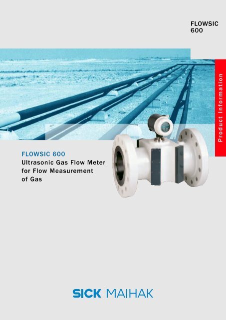
<strong>FLOWSIC</strong> <strong>600</strong><br />
<strong>Ultrasonic</strong> <strong>Gas</strong> <strong>Flow</strong> <strong>Meter</strong><br />
<strong>for</strong> <strong>Flow</strong> <strong>Measurement</strong><br />
<strong>of</strong> <strong>Gas</strong><br />
<strong>FLOWSIC</strong><br />
<strong>600</strong><br />
Product In<strong>for</strong>mation
Product In<strong>for</strong>mation<br />
<strong>FLOWSIC</strong> <strong>600</strong><br />
Benefits <strong>of</strong> <strong>FLOWSIC</strong> <strong>600</strong><br />
■ Compact design with concealed cabling system ➔ Robust, low-maintenance measuring system<br />
■ 1, 2 or 4 measuring paths ➔ Scalable per<strong>for</strong>mance<br />
■ 3D installation length, two pulse outputs ➔ Installed turbine meters can be replaced<br />
by <strong>FLOWSIC</strong> <strong>600</strong> without pipe change<br />
■ Power consumption < 1W ➔ Option <strong>for</strong> solar panel supply and battery<br />
operation<br />
■ Continuous parameter monitoring ➔ Reliability by self-diagnosis<br />
■ Compatible with all major flow computers ➔ Optimum self-integration<br />
Benefits <strong>of</strong> ultrasonic technology<br />
■ No moving parts, no wear and tear<br />
■ No overload possible<br />
■ Wide measuring range<br />
■ Bi-directional measurement<br />
■ No pressure loss<br />
Industries<br />
■ Natural gas industry (production, transportation,<br />
distribution, storage)<br />
■ <strong>Gas</strong>-fired power stations<br />
■ Chemical and petrochemical industry<br />
■ Fertilizer plants<br />
■ Biogas plants<br />
Measuring Principle<br />
Two ultrasonic transducers, which are installed<br />
under an angle to the flow axis, operate alternately<br />
as a transmitter and receiver. The signals transmitted<br />
through the gas accelerate in the direction <strong>of</strong><br />
flow and decelerate against the direction <strong>of</strong> flow.<br />
The resulting difference in propagation times is calculated<br />
using geometric variables to determine the<br />
mean gas velocity. The cross-sectional area yields<br />
the volumetric flow during operation. The measurement<br />
result is not affected by the pressure, temperature,<br />
or gas composition.<br />
To increase the accuracy <strong>of</strong> the measurement, the<br />
gas velocity is measured with multiple paths.<br />
<strong>Flow</strong><br />
D 2 · π<br />
Q= v·<br />
4<br />
Transducer A<br />
L 1 1<br />
v=<br />
2·cos � tv tr Transducer B<br />
v= <strong>Gas</strong> velocity<br />
L= Path length<br />
�= Path angle<br />
Q= <strong>Flow</strong> Rate<br />
D= Diameter
Path layout<br />
The <strong>FLOWSIC</strong> <strong>600</strong> is designed as a direct path ultrasonic<br />
meter without reflection points. This ensures<br />
that contamination or changes in wall roughness do<br />
not affect its measurement characteristics or longterm<br />
stability. In addition the layout <strong>of</strong> the measuring<br />
paths improves the signal-to-noise ratio.<br />
Since the measuring paths are in one plane, the<br />
influence <strong>of</strong> tangential flow constituents (e.g. swirl<br />
flow) can be compensated.<br />
Redundancy<br />
The <strong>FLOWSIC</strong> <strong>600</strong> can easily be extended to a redundant<br />
system. This can be achieved by adding one,<br />
two, or four measuring paths in the free part <strong>of</strong> the Xshaped<br />
measuring section and installing an additional<br />
electronic unit at the meter body. As a result, the<br />
main and the additional meter <strong>for</strong>m a redundant<br />
system which is integrated in one meter body.<br />
Self-diagnosis<br />
The electronics provide all the relevant parameters.<br />
Deviations <strong>of</strong> key values (e.g. sound velocity, signal<br />
gain, fault rate) are signaled immediately by alarm<br />
messages. In this way, deviations can be identified<br />
and removed be<strong>for</strong>e the measurement fails.<br />
The MEPAFLOW <strong>600</strong> s<strong>of</strong>tware allows you to access<br />
the data online.
<strong>FLOWSIC</strong> <strong>600</strong><br />
<strong>Flow</strong> Rate (a.c.) 8 ... 32,000 m3 /h, 280 ... 1,130,000 ft3 /h<br />
<strong>Gas</strong> velocity 0.3 ... 65 m/s, 1 ... 210 ft/s<br />
<strong>Gas</strong> temperature –30 ... +180 °C, –22 ... +356 °F<br />
Size glass G 250 to G 16,000<br />
Qmax / Qmin max. 130 : 1<br />
PTB<br />
NMI<br />
GOST<br />
A.G.A.9 The <strong>Ultrasonic</strong> (R)evolution
Technical data <strong>FLOWSIC</strong> <strong>600</strong><br />
Sensor characteristics<br />
Material Steel (1.1120 / ASME A216 WCC) or stainless steel (1.4581 / ASME A351 CF 10MC) *<br />
<strong>Meter</strong> size * <strong>Flow</strong> rate in m3 /h <strong>Flow</strong> rate in ft3 /h Velocity Length Weight<br />
Min. Max. Min. Max. Max.[m/s] [mm] (ANSI <strong>600</strong>) [kg]<br />
DN80 3“<br />
8 1,000 280 35,000 65 240 35<br />
DN100 4“<br />
13 1,<strong>600</strong> 460 57,000 60 300 55<br />
DN150 6“<br />
32 3,000 1,130 106,000 50 450 108<br />
DN200 8“<br />
40 4,500 1,410 159,000 45 <strong>600</strong> 168<br />
DN250 10“<br />
50 7,000 1,770 247,000 40 750 320<br />
DN300 12“<br />
65 8,000 2,300 283,000 33 900 420<br />
DN350 14“<br />
80 10,000 2,830 353,000 33 1,050 650<br />
DN400 16“ 120 14,000 4,240 494,000 33 1,200 770<br />
DN450 18“ 130 17,000 4,590 <strong>600</strong>,000 33 1,350 1,250<br />
DN500 20“ 200 20,000 7,060 706,000 33 1,500 1,<strong>600</strong><br />
DN<strong>600</strong> 24“ 320 32,000 11,300 1,130,000 33 1,800 2,500<br />
Measured medium<br />
<strong>Gas</strong>es Natural gas, process gas, air<br />
Temperature –30 °C ... +180 °C (–22 °F to 356 °F), up to 250 °C (482 °F) on request<br />
Pressure range 0 barg .. 100 barg (up to 450 barg on request)<br />
<strong>Measurement</strong> accuracy<br />
Reproducibility < 0.2 % <strong>of</strong> reading<br />
Typical measurement accuracy ** 1 measuring path ± 2.0 %<br />
2 measuring paths ± 1.0 %<br />
4 measuring paths ± 0.5 % ; ± 0.2 % with high-pressure calibration<br />
Power supply<br />
Operating voltage 12 .. 28.8 V DC<br />
Typical power consumption < 1 W<br />
Outputs<br />
Measured variables <strong>Flow</strong> rate (a.c.), volume (a.c.), velocity <strong>of</strong> gas, velocity <strong>of</strong> sound<br />
Current output active / passive; electrically isolated; 4 ... 20 mA; max. load = 250 Ω<br />
Pulse and switching outputs Passive, electrically insulated, open collector or NAMUR, fmax = 6 kHz<br />
Serial Modbus, RS485, parametrization, measured values, diagnosis<br />
HART ® Interfaces<br />
Parametrization, measured values and diagnosis<br />
Ambient conditions<br />
Degree <strong>of</strong> protection IP67<br />
Temperature range –40 °C .. +60 °C (–40 °F to 140 °F)<br />
Type <strong>of</strong> protection<br />
Europe II 1/2G EEx de ib [ia] IIA or IIC T4 according to ATEX<br />
USA/Canada Class I, Division 1, Groups B, C, D T4; Class I, Division 2,<br />
Groups A, B, C, D T4<br />
* Others on request<br />
** Qt .. Qmax with straigth inlet/outlet section 10D/3D or 5D/3D with flow straightener
Total length <strong>of</strong> measuring distance<br />
<strong>Meter</strong> size Total length with 16D [mm] Total length with 11D [mm]<br />
DN80 3“<br />
1,280 880<br />
DN100 4“<br />
1,<strong>600</strong> 1,100<br />
DN150 6“<br />
2,400 1,650<br />
DN200 8“<br />
3,200 2,200<br />
DN250 10“<br />
4,000 2,750<br />
DN300 12“<br />
4,800 3,300<br />
DN350 14“<br />
5,<strong>600</strong> 3,850<br />
DN400 16“<br />
6,400 4,400<br />
DN450 18“<br />
7,200 4,950<br />
DN500 20“<br />
8,000 5,500<br />
DN<strong>600</strong> 24“<br />
9,<strong>600</strong> 6,<strong>600</strong><br />
Installation<br />
<strong>Flow</strong>computer<br />
Configuration 1 Configuration 2<br />
Configuration 1<br />
(without flow straightener)<br />
Extraction tool <strong>for</strong> exchanging<br />
ultrasonic transducers<br />
under operating conditions<br />
Configuration 2<br />
(with flow straightener)
F a x a R e p l y<br />
w w w . s i c k - m a i h a k . c o m<br />
Company<br />
Name<br />
Job Title/Dept.<br />
Street<br />
ZIP, City<br />
Phone/Fax<br />
The dialogue continues.<br />
Copy, complete and fax to +49 7641 469 1149<br />
Industry/Field<br />
<strong>of</strong> Application Pl 103 en<br />
Yes, I would like to know more about<br />
the field <strong>of</strong>:<br />
In-process gas analysis<br />
Flue gas monitoring<br />
Emission monitoring<br />
Dust measurement<br />
Volume flow measurement<br />
Data acquisition and evaluation<br />
Water analysis<br />
Liquid analysis<br />
Level measurement<br />
Tunnel sensors<br />
Special measurement technology<br />
I would like a detailed consultation with one<br />
<strong>of</strong> your project advisors. Please arrange a<br />
meeting <strong>for</strong> me.<br />
Download more Product In<strong>for</strong>mations at www.sick-maihak.com<br />
SICK MAIHAK GmbH • Analyzers & Process Instrumentation • Nimburger Str. 11 • 79276 Reute • Germany<br />
Phone +49 7641 469 1772 • Fax +49 7641 469 1777 • www.sick-maihak.com • E-Mail: info_sick-maihak@sick.de<br />
8 009 840/09-2004/DIV 03.BW • Printed in Germany (10-2004) • Subject to change without prior notice