Industrial Gas Springs - ACE Controls International
Industrial Gas Springs - ACE Controls International
Industrial Gas Springs - ACE Controls International

Create successful ePaper yourself
Turn your PDF publications into a flip-book with our unique Google optimized e-Paper software.
162<br />
162<br />
<strong>Gas</strong> springs are universally accepted,<br />
wherever you want to<br />
• push<br />
• pull<br />
• lift<br />
• lower, or<br />
• position<br />
covers, lids or other components by hand<br />
without using an external energy source.<br />
<strong>ACE</strong> gas springs are individually filled to a<br />
predetermined pressure to suit a customer’s<br />
requirement (extension Force F1). The<br />
cross-sectional area of the piston rod and<br />
filling pressure determines the extension<br />
force F = p*A. During the compression of<br />
the piston rod, nitrogen flows through an<br />
orifice in the piston from the full bore side<br />
of the piston to the annulus. The nitrogen<br />
is compressed by the volume of the piston<br />
rod. As the piston rod is compressed the<br />
pressure increases, so increasing the<br />
reaction force (progression). The force<br />
depends on the proportional relationship<br />
between the piston rod and the inner tube<br />
diameter, which is approximately linear.<br />
<strong>Gas</strong> <strong>Springs</strong> (Push Type)<br />
Type<br />
1 Progression 2 Friction FR approx. % approx. in N<br />
GS-8 28 10<br />
GS-10 20 10<br />
GS-12 25 20<br />
GS-15 27 20<br />
GS-19 36 - 42 3 30<br />
GS-22 39 - 50 3 30<br />
GS-28 60 - 95 3 40<br />
GS-40 47 - 53 3 50<br />
GS-70 25 50<br />
Service Life<br />
<strong>Industrial</strong> <strong>Gas</strong> <strong>Springs</strong><br />
Function, Calculation and Mounting Tips<br />
Filling tolerance: -20 N to +40 N or 5% to 7%<br />
Effect of temperature: An increase in temperature of each 10 °C<br />
will increase force by approx. 3.4 %.<br />
Temperature range: -20 °C to +80 °C (special seals from -45 °C<br />
to 200 °C)<br />
Mounting: The gas springs should ideally be installed with the piston<br />
rod pointing downwards to use the end damping during the extension<br />
stroke to smoothly decelerate the motion of the gas spring. Some <strong>ACE</strong><br />
gas springs have a uniquely designed front bearing with an integrated<br />
grease chamber allowing the gas spring to be mounted and operated in<br />
any position if required.<br />
When fitting the gas springs ensure that the stroke is fully<br />
extended (GZ type fully compressed), this makes assembly and<br />
disassembly much easier. Support the moving mass/flap during<br />
assembly or disassembly to prevent accidents. To avoid twisting<br />
or side loading, it is recommended that ball joints or other pivoted<br />
mounting attachments are used. The mounting attachments must<br />
always be securely tightened onto the threaded studs of the gas spring.<br />
Force-Stroke Characteristics of <strong>Gas</strong> Spring (Push Type)<br />
5<br />
5<br />
F 3<br />
F 4 Outward Stroke<br />
F 2<br />
Compression<br />
Extension<br />
F1 Total Stroke mm<br />
Inward Stroke<br />
Total Stroke mm<br />
F 4<br />
F 1<br />
<strong>ACE</strong> gas springs are maintenance-free. DO NOT oil or grease the piston<br />
rod!<br />
The piston rod must be protected from any hits, scratches or dirt and<br />
especially paint. Damage to the surface finish of the piston rod will<br />
destroy the sealing system and cause loss of pressure. The outer body<br />
must not be deformed or mechanically damaged.<br />
<strong>ACE</strong> gas springs can be stored in any position. Experience has shown<br />
that long storage periods do not result in loss of pressure. However you<br />
may experience some “stiction” requiring a higher effort to move the gas<br />
spring for the first time after a long storage period.<br />
Generally, <strong>ACE</strong> gas springs are tested to 70 000 to 100 000 complete<br />
strokes. This is equivalent to the seal lifetime (depending on model size)<br />
to a distance travelled of 2 km up to 10 km. During these tests the gas<br />
spring must not lose more than 5% of its pressure. Depending upon the<br />
application and operating environment, the service life of these gas<br />
springs may be much longer. In practise 500 000 strokes or more have<br />
been achieved on some applications.<br />
Lifetime for traction gas spring see pages 189 to 197.<br />
Stoßdämpfer GmbH · PO Box 1510 · D-40740 Langenfeld · Tel. +49-2173-9226-4100 · Fax +49-2173-9226-89 · E-Mail: info@ace-int.eu<br />
F 2<br />
F 3<br />
5<br />
5<br />
F R<br />
F 1 = nominal force at 20 °C (this is the pressure figure normally used when specifying<br />
the gas spring)<br />
F 2 = force in the complete compressed position<br />
F R<br />
When compressing the piston rod, there is an additional friction force<br />
caused by the contact pressure of the seals (this only occurs during<br />
the compression stroke) F R<br />
F 3 = force at the beginning of the compression stroke<br />
F 4 = force at the end of the compression stroke<br />
Force-Stroke Characteristics of Traction <strong>Gas</strong> Spring (Pull Type)<br />
When extending the piston rod, there is an additional friction force<br />
caused by the contact pressure of the seals (this only occurs during<br />
the extension stroke) F R<br />
F 3 = force at the beginning of the extension stroke<br />
F 4 = force at the end of the extension stroke<br />
F 1 = nominal force at 20 °C (this is the pressure figure normally used when specifying<br />
the gas spring)<br />
F 2 = force in the complete extended position<br />
<strong>Gas</strong> <strong>Springs</strong> (Pull Type)<br />
Type<br />
1 Progression 2 Friction FR approx. % approx. in N<br />
GZ-15 23 55 - 140<br />
GZ-19 10 20 - 40<br />
GZ-28 20 100 - 200<br />
GZ-40 40<br />
1 The progression (the slope of the force line in the<br />
diagrams above) is due to the reduction of the internal<br />
gas volume as the piston rod moves from its initial position<br />
to its fully stroked position. The approx. progression values<br />
given above for standard springs can be altered on request.<br />
Effect of temperature: The nominal F1 figure is given at<br />
20 °C. An increase of 10 °C will increase force by 3.4%.<br />
Filling tolerance on F1 force: -20 N to +40 N<br />
or 5% to 7%<br />
2 Depending on the filling force.<br />
3 Depending on the stroke.<br />
Issue 6.2011 Specifications subject to change
Issue 6.2011 Specifications subject to change<br />
Adjustment Instructions Valve<br />
GS GZ<br />
<strong>Gas</strong> Spring Refilling Kit<br />
<strong>Industrial</strong> <strong>Gas</strong> <strong>Springs</strong><br />
Adjustment Instructions Valve, Filling Kit<br />
Adjustment Instruction<br />
1. Hold gas spring piston rod down.<br />
2. Remove any fitting attached to the body end of the gas spring<br />
(GZ-19 to GZ-40 version the piston rod).<br />
3. Insert adjuster knob on thread end on the cylinder body (on GZ-19<br />
to GZ-40 version thread end on the piston rod). When resistance is<br />
felt, proceed slowly and with caution. This opens the valve and you<br />
can hear the nitrogen escaping and reducing pressure. Turn back the<br />
adjusting knob immediately, to avoid too much nitrogen being<br />
discharged.<br />
4. After adjustment, remove the adjuster knob, mount the end fittings<br />
and test the gas spring in your application. If necessary repeat the<br />
procedure.<br />
If you use 2 gas springs in parallel, both gas springs should have the<br />
same force to avoid bending forces or side load on the application. If<br />
necessary return to <strong>ACE</strong> to refill both gas springs to the same (average)<br />
force. If too much nitrogen is discharged, the units can be returned to<br />
<strong>ACE</strong> for re-gassing.<br />
The <strong>ACE</strong> gas spring refilling kit offers you the opportunity to fill gas<br />
springs on location or adapt them individually. The refilling kit is equipped<br />
with all the parts you need to fill gas springs. Very precise filling of the<br />
gas springs is possible using the digital manometer. The table for<br />
determining the filling pressure of the gas springs is included with the<br />
case. The only thing missing from the delivery is the nitrogen.<br />
The refilling kit contains all filling bells and adjuster knobs for the current<br />
<strong>ACE</strong> gas spring range.<br />
Ordering name: Complete gas spring refilling kit<br />
“Independence and<br />
flexibility!”<br />
The refilling kit suits 200 bar nitrogen bottles with a thread of<br />
W24,32x1/14" (German standard). Other connections are available<br />
upon request.<br />
<strong>Gas</strong> springs filled with the refilling kit must be measured on a calibrated<br />
measurement system by <strong>ACE</strong> for repeat production.<br />
Stoßdämpfer GmbH · PO Box 1510 · D-40740 Langenfeld · Tel. +49-2173-9226-4100 · Fax +49-2173-9226-89 · E-Mail: info@ace-int.eu<br />
163<br />
163
164<br />
164<br />
Calculation<br />
To obtain the ideal selection to give the<br />
optimum operation for a gas spring it is<br />
important to identify the following points:<br />
• gas spring size<br />
• required gas spring stroke<br />
• mounting points on flap and frame<br />
• extended length of the gas spring<br />
• required extension force<br />
• hand forces throughout the complete<br />
movement on the flap<br />
With our free calculation service you can<br />
eliminate the time-consuming calculation and<br />
send us your details by fax or e-mail. Just<br />
complete the information shown on the calculation<br />
formulae page number 165. Please<br />
attach a sketch of your application (a simple<br />
hand sketch is sufficient) in side view. Our<br />
application engineers will determine the<br />
optimum gas springs and mounting points and<br />
calculate the ideal situation to satisfy your<br />
requirements.<br />
You will receive a quotation showing the opening and closing forces and<br />
our recommended mounting points to suit your application.<br />
Safety Instructions<br />
<strong>Industrial</strong> <strong>Gas</strong> <strong>Springs</strong><br />
Calculation and Safety Instructions<br />
<strong>Gas</strong> springs are filled with pure nitrogen gas. Nitrogen is an inert gas<br />
that does not burn or explode and is not poisonous.<br />
Please note!: the internal pressure of gas springs can be up to<br />
300 bar. Do not attempt to open or modify them.<br />
<strong>ACE</strong> gas springs will operate in surrounding temperatures from -20 °C<br />
to +80 °C. We can equip our springs with special seals to withstand<br />
temperatures as low as -45 °C or as high as +200 °C. <strong>Gas</strong> springs should<br />
not be placed over heat or in open fire!<br />
Disposal/Recycling: <strong>Gas</strong> <strong>Springs</strong> consist mostly of metal and the<br />
metal could be recycled, but first the gas pressure must be removed.<br />
Please ask for our disposal recommendations which advise how to<br />
depressurize the gas springs and make them safe to recycle.<br />
All gas springs are marked with the part number, the production date<br />
and a warning sign “Do not open high pressure”. We are not responsible<br />
for any damages of any kind that arises due to goods that are not<br />
marked accordingly.<br />
<strong>Gas</strong> springs should be installed with the piston rod downwards. This<br />
position ensures best damping quality. Only <strong>ACE</strong> gas springs include<br />
an integrated grease chamber which allows for alternative<br />
mounting opportunities.<br />
“Calculation offer<br />
with all required details<br />
for assembly!”<br />
<strong>Gas</strong> springs should not be exposed to tilting or side load forces during<br />
operation or whilst static (this can cause bending of the piston rod or<br />
early wear).<br />
<strong>Gas</strong> springs are maintenance-free. Do not grease or oil the piston<br />
rod.<br />
The piston rod must not be painted and should be protected against<br />
shocks, scratches and dirt. The cylinder should not be deformed as such<br />
damage would destroy the sealing system.<br />
<strong>ACE</strong> gas springs can be stored in any position. Pressure lost through<br />
long storage is not to be expected. There are no known negative values,<br />
but there may be a sticking effect the first time you compress a spring.<br />
This may require a higher initial force to operate the gas spring for the<br />
first time (initial breakaway force).<br />
The tolerance for the installation length is generally deemed to be<br />
± 2 mm. If very high demands are placed on durability and stability,<br />
please avoid the combination of small diameter + long stroke + high<br />
force.<br />
The filling tolerance is -20 N to 40 N or 5% to 7%.<br />
Stoßdämpfer GmbH · PO Box 1510 · D-40740 Langenfeld · Tel. +49-2173-9226-4100 · Fax +49-2173-9226-89 · E-Mail: info@ace-int.eu<br />
Issue 6.2011 Specifications subject to change
Issue 6.2011 Specifications subject to change<br />
Push type Pull type<br />
Input date<br />
<strong>Gas</strong> spring fixing points<br />
The fixed point of the frame and the moving point of the flap are<br />
critical for the optimum operation.<br />
Therefore please attach a sketch of your application<br />
(a few lines with their dimensions are sufficient)!<br />
Moving mass* m kg<br />
Number of gas springs in parallel* n pcs<br />
Number of movements* /day<br />
Ambient temperature<br />
If not shown by the sketch:<br />
T °C<br />
Radius of centre of gravity RM mm<br />
Radius of hand force RH mm<br />
Starting angle (0° to 360°) °<br />
Opening angle (–360° to +360°)<br />
(– = downwards, + = upwards)<br />
α °<br />
* Compulsory information<br />
Sketch:<br />
Please copy, complete and fax to <strong>ACE</strong>:<br />
Fax +49-(0)2173-9226-89<br />
<strong>Industrial</strong> <strong>Gas</strong> <strong>Springs</strong><br />
Calculation Formulae<br />
Please send us a sketch with dimensions of your application!<br />
Without this sketch we won’t be able to calculate.<br />
End Fitting<br />
The end fittings are interchangeable.<br />
e.g. -CE: C = Angle Ball Joint, E = Swivel Eye<br />
Stoßdämpfer GmbH · PO Box 1510 · D-40740 Langenfeld · Tel. +49-2173-9226-4100 · Fax +49-2173-9226-89 · E-Mail: info@ace-int.eu<br />
A<br />
B<br />
C<br />
D<br />
E<br />
F<br />
G<br />
Comments<br />
Requirement per year<br />
Machine type / reference<br />
Sender<br />
Company<br />
Address<br />
Internet<br />
Dept.<br />
Name<br />
Desired Mounting Fittings<br />
Stud Thread<br />
Angle Ball Joint<br />
Clevis Fork<br />
Swivel Eye<br />
Inline Ball Joint<br />
Ball Socket<br />
Telephone Fax<br />
E-Mail<br />
End Fitting<br />
A<br />
B<br />
C<br />
D<br />
E<br />
F<br />
G<br />
165<br />
165
166<br />
166<br />
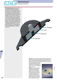
<strong>ACE</strong> industrial gas springs are maintenance-free<br />
and self-contained. They are avail-<br />
able with body diameters from 8 mm up to<br />
70 mm, and forces from 10 N up to 13 000 N<br />
ex. stock. <strong>ACE</strong> gas springs offer a high<br />
service life with a wear-resistant coating<br />
on the piston rod. Also an integrated low<br />
friction bearing with grease chamber<br />
which provides a very low break away<br />
force (GS-19 to GS-40). It allows them to<br />
be mounted in any orientation, although rod<br />
downwards is preferable if you want to take<br />
advantage of the built-in end position damping.<br />
The valve allows the force to be adjusted to<br />
your specific requirements. A wide variety of<br />
interchangeable end fittings makes installation<br />
easy and versatile. <strong>ACE</strong> gas springs are uni-<br />
versally applicable wherever you have lifting<br />
and lowering. They remove the need for “muscle<br />
power” and provide controlled motion for lids,<br />
hoods, machine guards etc. The <strong>ACE</strong> selection<br />
software quickly specifies the correct gas<br />
spring for your individual application and we<br />
can deliver, usually within 24 hours.<br />
<strong>Industrial</strong> <strong>Gas</strong> <strong>Springs</strong> GS-8 to GS-70 (Push Type)<br />
“Force adjustable to your<br />
specific requirements – with<br />
gas valve ex. stock!”<br />
Piston Rod<br />
Bearing Bush<br />
Filled with High<br />
Pressure<br />
Nitrogen <strong>Gas</strong><br />
Precision Steel Tube<br />
Metering Orifice for Controlled<br />
Extension and Compression<br />
Velocities<br />
Oil Zone for End Position Damping and<br />
Lubrication (recommended mounting<br />
position: piston rod downwards)<br />
Integral Grease Chamber<br />
for Increased Lifetime<br />
<strong>Gas</strong> Valve<br />
Function: <strong>ACE</strong> industrial gas springs provide a maintenance-free sealed<br />
for life system, being filled with high pressure nitrogen gas. The oil zone<br />
filling provides end position damping and internal lubrication for a long<br />
lifetime. On the extension stroke of the gas spring, for example when<br />
opening a car tailgate, the nitrogen gas flows through the metering orifice<br />
in the piston to provide a controlled opening speed and the oil zone<br />
provides damping at the fully open position to avoid impact damage.<br />
The gas spring should be mounted “rod down” for this damping to be<br />
effective. On closing the tailgate the<br />
gas spring helps support the weight.<br />
The metering orifice controls the<br />
extension and compression velocities<br />
of the gas spring.<br />
Operating fluid: Nitrogen gas<br />
and oil<br />
Mounting: In any position<br />
Operating temperature range:<br />
-20 °C to 80 °C<br />
On request: Without damping,<br />
extended length damping, special<br />
force curves, , special lengths,<br />
alternative end fittings.<br />
Issue 6.2011 Specifications subject to change
Issue 6.2011 Specifications subject to change<br />
<strong>Industrial</strong> <strong>Gas</strong> <strong>Springs</strong> GS-8 (Push Type)<br />
Extension Forces 10 N to 100 N<br />
(when Piston Rod Compressed up to 130 N)<br />
End Fitting Standard Dimensions<br />
End Fitting<br />
Radius<br />
R4<br />
4<br />
7<br />
Ø 8<br />
Ø 4.1<br />
24° 7,8<br />
7.3<br />
12<br />
Ø13<br />
18<br />
5<br />
Ø 8<br />
6<br />
Ø 8<br />
4 thick<br />
A3,5 Eye A3,5<br />
max. force 370 N<br />
8<br />
Ø 3<br />
Ø 8 8<br />
Stroke<br />
12 L+/- 2 mm extended<br />
12<br />
B3,5 M3.5x0.6 Dimensions<br />
Stud Thread B3,5<br />
C3,5 Ø13 5<br />
Ø 8<br />
Type<br />
GS-8-20<br />
GS-8-30<br />
Stroke<br />
mm<br />
20<br />
30<br />
L<br />
extended<br />
72<br />
92<br />
5<br />
Angle Ball Joint C3,5<br />
max. force 370 N<br />
GS-8-40 40 112<br />
8.5<br />
6<br />
GS-8-50<br />
GS-8-60<br />
50<br />
60<br />
132<br />
152<br />
10<br />
18<br />
M4x0.7<br />
GS-8-80 80 192<br />
18<br />
D3,5<br />
36°<br />
Ø 4<br />
Ordering Example<br />
Type (Push Type)<br />
Body Ø (8 mm)<br />
GS-8-30-AC-30<br />
Clevis Fork D3,5<br />
max. force 370 N<br />
8 4 Stroke (30 mm)<br />
Piston Rod End Fitting A3,5<br />
E3,5<br />
5<br />
7<br />
8<br />
16<br />
Ø<br />
Ø 4<br />
5.3<br />
Body End Fitting C3,5<br />
Nominal Force F1 30 N<br />
The end fittings are interchangeable.<br />
For mounting accessories see page 199.<br />
16<br />
Swivel Eye E3,5<br />
max. force 370 N<br />
G3,5<br />
Rod Shroud<br />
W3,5-8<br />
Ø 11<br />
L = Stroke + 10<br />
GS-8<br />
For mounting<br />
accessories<br />
see page 199.<br />
Technical Data<br />
Stoßdämpfer GmbH · PO Box 1510 · D-40740 Langenfeld · Tel. +49-2173-9226-4100 · Fax +49-2173-9226-89 · E-Mail: info@ace-int.eu<br />
4 thick<br />
5<br />
12<br />
18<br />
Ø4.1<br />
Ball Socket G3,5<br />
max. force 370 N<br />
Adjuster Knob U3,5<br />
See page 163.<br />
On request: Without damping, extended length damping, special force<br />
curves, special lengths, alternative end fittings.<br />
Available force range F1 at 20 °C: 10 N to 100 N<br />
Mounting: In any position<br />
Advice: We recommend mounting with piston rod downwards to take<br />
advantage of the built-in end position damping.<br />
End position damping length: Approx. 5 mm<br />
Material: Body: Black coated steel. Piston rod: Stainless steel<br />
(1.4305). End fittings: Zinc plated steel.<br />
Progression: Approx. 28 %, F2 max. 130 N<br />
167<br />
167
168<br />
168<br />
<strong>Industrial</strong> <strong>Gas</strong> <strong>Springs</strong> GS-10 (Push Type)<br />
Extension Forces 10 N to 100 N<br />
(when Piston Rod Compressed up to 120 N)<br />
End Fitting Standard Dimensions<br />
End Fitting<br />
Radius<br />
R4<br />
24° 7.8<br />
7.3 5<br />
12<br />
12<br />
7<br />
G3,5 Ø13<br />
Ball Socket G3,5<br />
Ø 8<br />
max. force 370 N<br />
4<br />
Ø 8<br />
Ø 4.1<br />
18<br />
6<br />
Ø 8<br />
4 thick<br />
A3,5 Eye A3,5<br />
max. force 370 N<br />
8<br />
Ø 3<br />
Ø 10 8<br />
Stroke<br />
12 L+/- 2 mm extended<br />
12<br />
B3,5 M3.5x0.6 Dimensions<br />
Stud Thread B3,5<br />
C3,5 Ø13 5<br />
Ø 8<br />
Type<br />
GS-10-20<br />
GS-10-30<br />
Stroke<br />
mm<br />
20<br />
30<br />
L<br />
extended<br />
72<br />
92<br />
5<br />
Angle Ball Joint C3,5<br />
max. force 370 N<br />
GS-10-40 40 112<br />
8.5<br />
6<br />
GS-10-50<br />
GS-10-60<br />
50<br />
60<br />
132<br />
152<br />
10<br />
18<br />
M4x0.7<br />
GS-10-80 80 192<br />
18<br />
D3,5<br />
36°<br />
Ø 4<br />
Ordering Example<br />
Type (Push Type)<br />
Body Ø (10 mm)<br />
GS-10-80-AC-60<br />
Clevis Fork D3,5<br />
max. force 370 N<br />
8 4 Stroke (80 mm)<br />
Piston Rod End Fitting A3,5<br />
E3,5<br />
5<br />
7<br />
8<br />
16<br />
Ø<br />
Ø 4<br />
5.3<br />
Body End Fitting C3,5<br />
Nominal Force F1 60 N<br />
The end fittings are interchangeable.<br />
For mounting accessories see page 199.<br />
16<br />
Swivel Eye E3,5<br />
max. force 370 N<br />
Rod Shroud<br />
W3,5-10<br />
Ø 13<br />
L = Stroke + 10<br />
GS-10<br />
For mounting<br />
accessories<br />
see page 199.<br />
Technical Data<br />
Stoßdämpfer GmbH · PO Box 1510 · D-40740 Langenfeld · Tel. +49-2173-9226-4100 · Fax +49-2173-9226-89 · E-Mail: info@ace-int.eu<br />
4 thick<br />
5<br />
18<br />
Ø4.1<br />
Adjuster Knob U3,5<br />
See page 163.<br />
On request: Without damping, extended length damping, special force<br />
curves, special lengths, alternative end fittings.<br />
Available force range F1 at 20 °C: 10 N to 100 N<br />
Mounting: In any position<br />
Advice: We recommend mounting with piston rod downwards to take<br />
advantage of the built-in end position damping.<br />
End position damping length: Approx. 5 mm<br />
Material: Body: Black coated steel. Piston rod: Stainless steel<br />
(1.4305). End fittings: Zinc plated steel.<br />
Progression: Approx. 20%, F2 max. 120 N<br />
Issue 6.2011 Specifications subject to change
Issue 6.2011 Specifications subject to change<br />
<strong>Industrial</strong> <strong>Gas</strong> <strong>Springs</strong> GS-12 (Push Type)<br />
Extension Forces 10 N to 180 N<br />
(when Piston Rod Compressed up to 225 N)<br />
End Fitting Standard Dimensions<br />
End Fitting<br />
Radius<br />
R4<br />
4<br />
Ø 8<br />
Ø 4.1<br />
24° 7.8<br />
18<br />
6<br />
Ø 8<br />
4 thick<br />
A3,5 Eye A3,5<br />
max. force 370 N<br />
8<br />
Ø 4<br />
Ø 12 8<br />
Stroke<br />
12 L+/- 2 mm extended<br />
12<br />
B3,5 M3.5x0.6 Dimensions<br />
Stud Thread B3,5<br />
C3,5 Ø13 5<br />
Ø 8<br />
Type<br />
GS-12-20<br />
GS-12-30<br />
Stroke<br />
mm<br />
20<br />
30<br />
L<br />
extended<br />
72<br />
92<br />
F1 max.<br />
N<br />
180<br />
180<br />
5<br />
Angle Ball Joint C3,5<br />
max. force 370 N<br />
GS-12-40 40 112 180<br />
8.5<br />
6<br />
GS-12-50<br />
GS-12-60<br />
50<br />
60<br />
132<br />
152<br />
180<br />
180<br />
D3,5<br />
10<br />
36°<br />
Ø 4<br />
18<br />
M4x0.7<br />
GS-12-80<br />
GS-12-100<br />
GS-12-120<br />
GS-12-150<br />
80<br />
100<br />
120<br />
150<br />
192<br />
232<br />
272<br />
332<br />
150<br />
150<br />
120<br />
100<br />
18<br />
Clevis Fork D3,5<br />
max. force 370 N<br />
Ordering Example GS-12-100-AA-30<br />
8 4<br />
Type (Push Type)<br />
5<br />
8<br />
16<br />
Body Ø (12 mm)<br />
Stroke (100 mm)<br />
16<br />
E3,5<br />
7<br />
Ø 4<br />
Ø<br />
5.3<br />
Piston Rod End Fitting A3,5<br />
Body End Fitting A3,5<br />
Nominal Force F1 30 N<br />
Swivel Eye E3,5<br />
max. force 370 N<br />
G3,5<br />
7<br />
7.3 5<br />
12<br />
Ø13<br />
Ø 8<br />
The end fittings are interchangeable.<br />
For mounting accessories see page 199.<br />
12<br />
Ball Socket G3,5<br />
max. force 370 N<br />
Rod Shroud<br />
W3,5-12<br />
Ø 15.6<br />
L = Stroke + 10<br />
GS-12<br />
For mounting<br />
accessories<br />
see page 199.<br />
Technical Data<br />
Stoßdämpfer GmbH · PO Box 1510 · D-40740 Langenfeld · Tel. +49-2173-9226-4100 · Fax +49-2173-9226-89 · E-Mail: info@ace-int.eu<br />
4 thick<br />
5<br />
18<br />
Ø4.1<br />
Adjuster Knob U3,5<br />
See page 163.<br />
On request: Without damping, extended length damping, special force<br />
curves, special lengths, alternative end fittings.<br />
Available force range F1 at 20 °C: 10 N to 180 N<br />
Mounting: In any position<br />
Advice: We recommend mounting with piston rod downwards to take<br />
advantage of the built-in end position damping.<br />
End position damping length: Approx. 10 mm<br />
Material: Body: Black coated steel. Piston rod: Stainless steel<br />
(1.4305). End fittings: Zinc plated steel.<br />
Progression: Approx. 25%, F2 max. 225 N<br />
169<br />
169
170<br />
170<br />
<strong>Industrial</strong> <strong>Gas</strong> <strong>Springs</strong> GS-15 (Push Type)<br />
Extension Forces 40 N to 400 N<br />
(when Piston Rod Compressed up to 500 N)<br />
End Fitting Standard Dimensions<br />
End Fitting<br />
Radius<br />
R5<br />
24° 10<br />
20<br />
4.5<br />
Ø 8<br />
Ø 6.1<br />
10<br />
28<br />
Ø13<br />
Ø 8<br />
22<br />
12<br />
Ø 10<br />
6 thick<br />
A5 Eye A5<br />
max. force 800 N<br />
10<br />
Ø 6<br />
Ø 15.6 10<br />
Stroke<br />
16 L+/- 2 mm extended<br />
16<br />
B5 M5x0.8 Dimensions<br />
Stud Thread B5<br />
C5 Ø13 5<br />
Ø 8<br />
Type<br />
GS-15-20<br />
GS-15-40<br />
Stroke<br />
mm<br />
20<br />
40<br />
L<br />
extended<br />
67<br />
107<br />
5<br />
Angle Ball Joint C5<br />
max. force 500 N<br />
GS-15-50 50 127<br />
8<br />
12<br />
GS-15-60<br />
GS-15-80<br />
60<br />
80<br />
147<br />
187<br />
D5<br />
10<br />
36°<br />
Ø 5<br />
22<br />
M5x0.8<br />
GS-15-100<br />
GS-15-120<br />
GS-15-150<br />
GS-15-200<br />
Ordering Example<br />
100<br />
120<br />
150<br />
200<br />
227<br />
267<br />
327<br />
427<br />
GS-15-150-AC-150<br />
22<br />
Clevis Fork D5<br />
max. force 800 N<br />
10 5<br />
Type (Push Type)<br />
E5 Ø 6<br />
6<br />
10<br />
20<br />
Ø<br />
4.5<br />
Ø13<br />
Body Ø (15.6 mm)<br />
Stroke (150 mm)<br />
Piston Rod End Fitting A5<br />
Body End Fitting C5<br />
20<br />
Swivel Eye E5<br />
max. force 800 N<br />
6<br />
Nominal Force F1 150 N<br />
F5<br />
10<br />
M5x0.8<br />
12<br />
45°<br />
30<br />
AF13<br />
12<br />
Ø 8<br />
The end fittings are interchangeable.<br />
For mounting accessories see page 199.<br />
30<br />
Inline Ball Joint F5<br />
max. force 500 N<br />
G5<br />
Rod Shroud<br />
W5-15<br />
Ø 19<br />
L = Stroke + 20<br />
GS-15<br />
For mounting<br />
accessories<br />
see page 199.<br />
Technical Data<br />
Stoßdämpfer GmbH · PO Box 1510 · D-40740 Langenfeld · Tel. +49-2173-9226-4100 · Fax +49-2173-9226-89 · E-Mail: info@ace-int.eu<br />
6 thick<br />
5<br />
22<br />
Ø 6.1<br />
On request: Without damping, increased damping action at end of<br />
travel, special force curves, special lengths, strokes, alternative end<br />
fittings, wiper, stainless steel (see pages 179 to 186).<br />
Available force range F1 at 20 °C: 40 N to 400 N<br />
Mounting: In any position<br />
Advice: We recommend mounting with piston rod downwards to take<br />
advantage of the built-in end position damping.<br />
End position damping length: Approx. 10 mm<br />
Material: Body: Black coated steel. Piston rod: With wear-resistant<br />
coating. End fittings: Zinc plated steel.<br />
Progression: Approx. 27%, F2 max. 500 N<br />
28<br />
Ball Socket G5<br />
max. force 500 N<br />
Adjuster Knob U5<br />
See page 163.<br />
Issue 6.2011 Specifications subject to change
Issue 6.2011 Specifications subject to change<br />
<strong>Industrial</strong> <strong>Gas</strong> <strong>Springs</strong> GS-19 (Push Type)<br />
Extension Forces 50 N to 700 N<br />
(when Piston Rod Compressed up to 995 N)<br />
End Fitting Standard Dimensions<br />
End Fitting<br />
8<br />
Radius<br />
R7<br />
24° 12<br />
13<br />
16<br />
36<br />
12<br />
36<br />
F8 M8x1.25 AF15<br />
Inline Ball Joint F8<br />
45°<br />
Ø12<br />
max. force 1200 N<br />
22<br />
6<br />
Ø 13<br />
Ø 8.1<br />
12<br />
31<br />
Ø20<br />
Ø13<br />
30<br />
15<br />
Ø 14<br />
10 thick<br />
A8 Eye A8<br />
max. force 3000 N<br />
14<br />
Ø 8<br />
Ø 19 14<br />
Stroke<br />
20 L+/- 2 mm extended<br />
20<br />
B8 M8x1.25<br />
Dimensions<br />
Stud Thread B8<br />
C8 Ø 20<br />
10<br />
Ø 13<br />
Type<br />
GS-19-50<br />
GS-19-100<br />
Stroke<br />
mm<br />
50<br />
100<br />
L<br />
extended<br />
164<br />
264<br />
10<br />
Angle Ball Joint C8<br />
max. force 1200 N<br />
GS-19-150 150 364<br />
12<br />
15<br />
GS-19-200<br />
GS-19-250<br />
200<br />
250<br />
464<br />
564<br />
16.5<br />
30<br />
GS-19-300 300 664<br />
30<br />
M8x1.25<br />
D8<br />
36°<br />
Ø 8<br />
Ordering Example<br />
Type (Push Type)<br />
Body Ø (19 mm)<br />
GS-19-150-AC-600<br />
Clevis Fork D8<br />
max. force 3000 N<br />
16 8 Stroke (150 mm)<br />
Piston Rod End Fitting A8<br />
Body End Fitting C8<br />
16<br />
E8<br />
10<br />
Ø 8<br />
6<br />
32<br />
Ø<br />
Ø 16<br />
Nominal Force F1 600 N<br />
32<br />
Swivel Eye E8<br />
max. force 3000 N<br />
G8<br />
Rod Shroud<br />
W8-19<br />
Ø 23<br />
The end fittings are interchangeable.<br />
For mounting accessories see page 200.<br />
L = Stroke + 30<br />
GS-19<br />
For mounting<br />
accessories<br />
see page 200.<br />
Technical Data<br />
Stoßdämpfer GmbH · PO Box 1510 · D-40740 Langenfeld · Tel. +49-2173-9226-4100 · Fax +49-2173-9226-89 · E-Mail: info@ace-int.eu<br />
10 thick<br />
10<br />
30<br />
Ø 8.1<br />
On request: Without damping, standard length damping, special force<br />
curves, special lengths, alternative end fittings, wiper, stainless steel<br />
(see pages 179 to 186).<br />
Available force range F1 at 20 °C: 50 N to 700 N<br />
Mounting: In any position<br />
Advice: We recommend mounting with piston rod downwards to take<br />
advantage of the built-in end position damping.<br />
End position damping length: Strong end position damping approx.<br />
20 to 60 mm (depending on the stroke) and slow extension speed.<br />
Material: Body: Black coated steel. Piston rod: With wear-resistant<br />
coating. End fittings: Zinc plated steel.<br />
Progression: Approx. 36% to 42%, F2 max. 995 N<br />
31<br />
Ball Socket G8<br />
max. force 1200 N<br />
Adjuster Knob U8<br />
See page 163.<br />
171<br />
171
172<br />
172<br />
<strong>Industrial</strong> <strong>Gas</strong> <strong>Springs</strong> GS-22 (Push Type)<br />
Extension Forces 80 N to 1300 N<br />
(when Piston Rod Compressed up to 1950 N)<br />
End Fitting Standard Dimensions<br />
End Fitting<br />
Radius<br />
R7<br />
24° 12<br />
22<br />
6<br />
Ø 13<br />
Ø 8.1<br />
12<br />
31<br />
Ø 20<br />
Ø13<br />
30<br />
15<br />
Ø14<br />
10 thick<br />
A8 Eye A8<br />
max. force 3000 N<br />
14<br />
Ø 10<br />
Ø 23 14<br />
Stroke<br />
20 L+/- 2 mm extended<br />
20<br />
B8 M8x1.25 Dimensions<br />
Stud Thread B8<br />
C8 Ø 20<br />
10<br />
Ø 13<br />
Type<br />
GS-22-50<br />
GS-22-100<br />
Stroke<br />
mm<br />
50<br />
100<br />
L<br />
extended<br />
164<br />
264<br />
10<br />
Angle Ball Joint C8<br />
max. force 1200 N<br />
GS-22-150 150 364<br />
12<br />
15<br />
GS-22-200<br />
GS-22-250<br />
200<br />
250<br />
464<br />
564<br />
D8<br />
16.5<br />
36°<br />
Ø 8<br />
30<br />
M8x1.25<br />
GS-22-300<br />
GS-22-350<br />
GS-22-400<br />
GS-22-450<br />
GS-22-500<br />
GS-22-550<br />
300<br />
350<br />
400<br />
450<br />
500<br />
550<br />
664<br />
764<br />
864<br />
964<br />
1 064<br />
1 164<br />
30<br />
Clevis Fork D8<br />
max. force 3000 N<br />
16 8<br />
GS-22-600<br />
GS-22-650<br />
600<br />
650<br />
1 264<br />
1 364<br />
16<br />
GS-22-700 700 1 464<br />
E8<br />
10<br />
Ø 8<br />
6<br />
32<br />
Ø<br />
Ø 16 Ordering Example<br />
Type (Push Type)<br />
GS-22-150-AE-800<br />
32<br />
Swivel Eye E8<br />
max. force 3000 N<br />
8<br />
Body Ø (23 mm)<br />
Stroke (150 mm)<br />
F8<br />
13<br />
12<br />
M8x1.25<br />
45°<br />
36<br />
AF15<br />
16<br />
Ø12<br />
Piston Rod End Fitting A8<br />
Body End Fitting E8<br />
Nominal Force F1 800 N<br />
36<br />
Inline Ball Joint F8<br />
max. force 1200 N<br />
G8<br />
Rod Shroud<br />
W8-22<br />
Ø 28<br />
The end fittings are interchangeable.<br />
For mounting accessories see page 200.<br />
L = Stroke + 30<br />
GS-22<br />
For mounting<br />
accessories<br />
see page 200.<br />
Technical Data<br />
Stoßdämpfer GmbH · PO Box 1510 · D-40740 Langenfeld · Tel. +49-2173-9226-4100 · Fax +49-2173-9226-89 · E-Mail: info@ace-int.eu<br />
10 thick<br />
10<br />
30<br />
Ø 8.1<br />
On request: Without damping, standard length damping, special force<br />
curves, special lengths, alternative end fittings, wiper, stainless steel<br />
(see pages 179 to 186).<br />
Available force range F1 at 20 °C: 80 N to 1300 N<br />
Mounting: In any position<br />
Advice: We recommend mounting with piston rod downwards to take<br />
advantage of the built-in end position damping.<br />
End position damping length: Strong end position damping approx.<br />
20 to 70 mm (depending on the stroke) and slow extension speed.<br />
Material: Body: Black coated steel. Piston rod: With wear-resistant<br />
coating. End fittings: Zinc plated steel.<br />
Progression: Approx. 39% to 50%, F2 max. 1950 N<br />
31<br />
Ball Socket G8<br />
max. force 1200 N<br />
Adjuster Knob U8<br />
See page 163.<br />
Issue 6.2011 Specifications subject to change
Issue 6.2011 Specifications subject to change<br />
<strong>Industrial</strong> <strong>Gas</strong> <strong>Springs</strong> GS-28 (Push Type)<br />
Extension Forces 150 N to 2500 N<br />
(when Piston Rod Compressed up to 4875 N)<br />
End Fitting Standard Dimensions<br />
End Fitting<br />
Radius<br />
R9<br />
Ø 8.1<br />
24° 15<br />
25<br />
43<br />
Ø 18<br />
12 thick<br />
A10 Eye A10<br />
max. force 10 000 N<br />
17<br />
Ø 14<br />
Ø 28 17<br />
Stroke<br />
25 L+/- 2 mm extended<br />
25<br />
B10 M10x1.5<br />
Dimensions<br />
Stud Thread B10<br />
C10 Ø 24<br />
12<br />
Ø16<br />
Type<br />
GS-28-100<br />
GS-28-150<br />
Stroke<br />
mm<br />
100<br />
150<br />
L<br />
extended<br />
262<br />
362<br />
12<br />
Angle Ball Joint C10<br />
max. force 1800 N<br />
GS-28-200 200 462<br />
16<br />
18<br />
GS-28-250<br />
GS-28-300<br />
250<br />
300<br />
562<br />
662<br />
D10<br />
20<br />
36°<br />
Ø10<br />
35<br />
M10x1.5<br />
GS-28-350<br />
GS-28-400<br />
GS-28-450<br />
GS-28-500<br />
GS-28-550<br />
GS-28-600<br />
350<br />
400<br />
450<br />
500<br />
550<br />
600<br />
762<br />
862<br />
962<br />
1 062<br />
1 162<br />
1 262<br />
35<br />
Clevis Fork D10<br />
max. force 10 000 N<br />
20 10<br />
GS-28-650<br />
GS-28-700<br />
650<br />
700<br />
1 362<br />
1 462<br />
20<br />
GS-28-750 750 1 562<br />
E10<br />
12<br />
Ø10<br />
7<br />
40<br />
Ø<br />
Ø19<br />
Ordering Example<br />
Type (Push Type)<br />
Body Ø (28 mm)<br />
GS-28-150-EE-1200<br />
40<br />
Swivel Eye E10<br />
max. force 10 000 N<br />
9<br />
Stroke (150 mm)<br />
16<br />
14<br />
F10<br />
M10x1.5<br />
45°<br />
43<br />
AF17<br />
18<br />
AF17<br />
Piston Rod End Fitting E10<br />
Body End Fitting E10<br />
Nominal Force F1 1200 N<br />
The end fittings are interchangeable.<br />
For mounting accessories see page 200.<br />
43<br />
Inline Ball Joint F10<br />
max. force 1800 N<br />
Rod Shroud<br />
W10-28<br />
19<br />
Ø 32<br />
L = Stroke + 40<br />
GS-28<br />
For mounting<br />
accessories<br />
see page 200.<br />
Technical Data<br />
Stoßdämpfer GmbH · PO Box 1510 · D-40740 Langenfeld · Tel. +49-2173-9226-4100 · Fax +49-2173-9226-89 · E-Mail: info@ace-int.eu<br />
12 thick<br />
12<br />
Ø 8.1<br />
On request: Without damping, standard length damping, special force<br />
curves, special lengths, alternative end fittings, wiper, stainless steel<br />
(see pages 179 to 186).<br />
Available force range F1 at 20 °C: 150 N to 2500 N<br />
Mounting: In any position<br />
Advice: We recommend mounting with piston rod downwards to take<br />
advantage of the built-in end position damping.<br />
End position damping length: Strong end position damping approx.<br />
30 to 70 mm (depending on the stroke) and slow extension speed.<br />
Material: Body: Black coated steel. Piston rod: With wear-resistant<br />
coating. End fittings: Zinc plated steel.<br />
Progression: Approx. 60% to 95%, F2 max. 4875 N<br />
43<br />
Adjuster Knob U10<br />
See page 163.<br />
173<br />
173
174<br />
174<br />
<strong>Industrial</strong> <strong>Gas</strong> <strong>Springs</strong> GS-40 (Push Type)<br />
Extension Forces 500 N to 5000 N<br />
(when Piston Rod Compressed up to 7650 N)<br />
End Fitting Standard Dimensions<br />
End Fitting<br />
19<br />
Radius<br />
R12.5<br />
Ø 14.1<br />
30° 20<br />
40<br />
56<br />
Ø 25<br />
14 thick<br />
A14 Eye A14<br />
max. force 10 000 N<br />
21<br />
Ø 20<br />
Ø 40 21<br />
Stroke<br />
40 L+/- 2 mm extended<br />
40<br />
B14 M14x1.5<br />
Dimensions<br />
Stud Thread B14<br />
C14<br />
Ø30 15<br />
Ø 22<br />
Type<br />
GS-40-100<br />
GS-40-150<br />
Stroke<br />
mm<br />
100<br />
150<br />
L<br />
extended<br />
317<br />
417<br />
15<br />
Angle Ball Joint C14<br />
max. force 3200 N<br />
GS-40-200 200 517<br />
20<br />
25<br />
GS-40-300<br />
GS-40-400<br />
300<br />
400<br />
717<br />
917<br />
D14<br />
28<br />
36°<br />
Ø14<br />
45<br />
M14x1.5<br />
GS-40-500<br />
GS-40-600<br />
GS-40-800<br />
GS-40-1000<br />
Ordering Example<br />
500<br />
600<br />
800<br />
1 000<br />
1 117<br />
1 317<br />
1 717<br />
2 117<br />
GS-40-150-DD-3500<br />
45<br />
Clevis Fork D14<br />
max. force 10 000 N<br />
27 14<br />
Type (Push Type)<br />
E14<br />
16<br />
Ø14<br />
27<br />
56<br />
Ø<br />
13<br />
Ø 26<br />
Body Ø (40 mm)<br />
Stroke (150 mm)<br />
Piston Rod End Fitting D14<br />
Body End Fitting D14<br />
Nominal Force F1 3500 N<br />
56<br />
Swivel Eye E14<br />
max. force 10 000 N<br />
18<br />
30<br />
57<br />
18<br />
57<br />
F14<br />
M14x1.5<br />
AF22<br />
Inline Ball Joint F14<br />
30°<br />
AF24<br />
max. force 3200 N<br />
Rod Shroud<br />
W14-40<br />
18<br />
Ø 45<br />
The end fittings are interchangeable.<br />
For mounting accessories see page 201.<br />
L = Stroke + 40<br />
GS-40<br />
For mounting<br />
accessories<br />
see page 201.<br />
Technical Data<br />
Stoßdämpfer GmbH · PO Box 1510 · D-40740 Langenfeld · Tel. +49-2173-9226-4100 · Fax +49-2173-9226-89 · E-Mail: info@ace-int.eu<br />
14 thick<br />
15<br />
Ø14.1<br />
On request: Without damping, standard length damping, special force<br />
curves, special lengths, alternative end fittings, wiper, stainless steel<br />
(see pages 179 to 186).<br />
Available force range F1 at 20 °C: 500 N to 5000 N<br />
Mounting: In any position<br />
Advice: We recommend mounting with piston rod downwards to take<br />
advantage of the built-in end position damping.<br />
End position damping length: Strong end position damping approx.<br />
30 to 70 mm (depending on the stroke) and slow extension speed.<br />
Material: Body: Black coated steel. Piston rod: With wear-resistant<br />
coating. End fittings: Zinc plated steel.<br />
Progression: Approx. 47 % to 53%, F2 max. 7650 N<br />
56<br />
Adjuster Knob U14<br />
See page 163.<br />
Issue 6.2011 Specifications subject to change
Issue 6.2011 Specifications subject to change<br />
<strong>Industrial</strong> <strong>Gas</strong> <strong>Springs</strong> GS-70 (Push Type)<br />
Extension Forces 2000 N to 13 000 N<br />
(when Piston Rod Compressed up to 16 250 N)<br />
End Fitting Standard Dimensions<br />
End Fitting<br />
B24 M24x2<br />
Stud Thread B24<br />
31<br />
30<br />
50<br />
Ø 25<br />
25<br />
50<br />
32 100<br />
30° 34<br />
Ø 25<br />
30<br />
Ø<br />
22<br />
94<br />
40<br />
35<br />
Ø 42<br />
Ø 80<br />
Ø<br />
30<br />
Stroke<br />
L = Stroke + 130<br />
L+/- 2 mm extended<br />
Stoßdämpfer GmbH · PO Box 1510 · D-40740 Langenfeld · Tel. +49-2173-9226-4100 · Fax +49-2173-9226-89 · E-Mail: info@ace-int.eu<br />
Ø 70<br />
Dimensions<br />
Type<br />
Stroke<br />
L<br />
mm<br />
extended<br />
GS-70-100 100 320<br />
GS-70-200 200 520<br />
GS-70-300 300 720<br />
GS-70-400 400 920<br />
GS-70-500 500 1 120<br />
GS-70-600 600 1 320<br />
GS-70-700 700 1 520<br />
GS-70-800 800 1 720<br />
D24 Clevis Fork D24<br />
Ordering Example GS-70-200-EE-8000<br />
Type (Push Type)<br />
Body Ø (70 mm)<br />
Stroke (200 mm)<br />
Piston Rod End Fitting E24<br />
Body End Fitting E24<br />
Nominal Force F1 8000 N<br />
The end fittings are interchangeable.<br />
For mounting accessories see page 201.<br />
Standard gas spring with valve.<br />
Technical Data<br />
On request: Without damping, extended length damping, special force<br />
curves, special lengths, alternative end fittings, wiper, stainless steel.<br />
Available force range F1 at 20 °C: 2000 N to 13 000 N<br />
Mounting: In any position<br />
Advice: We recommend mounting with piston rod downwards to take<br />
advantage of the built-in end position damping.<br />
End position damping length: Approx. 10 mm<br />
Material: Body: Black coated steel or zinc plated steel. Piston rod: Hard<br />
chrome plated. End fittings: Zinc plated steel.<br />
Progression: Approx. 25%, F2 max. 16 250 N<br />
35<br />
100<br />
94<br />
max. force 50 000 N<br />
E24 Swivel Eye E24<br />
Rod Shroud<br />
W24-70<br />
GS-70<br />
For mounting<br />
accessories<br />
see page 201.<br />
max. force 50 000 N<br />
175<br />
175
176<br />
176<br />
<strong>ACE</strong> offers tandem gas springs specially for<br />
heavy flaps and hoods with a large opening<br />
angle. These are characterised by a high initial<br />
force and low end force. The tandem gas<br />
springs have two pressure tubes with different<br />
extension forces and progression curves, and<br />
are therefore able to cover two force ranges.<br />
The tandem gas springs are designed<br />
specifically for your application. The force<br />
ranges are matched exactly to each other and<br />
adjusted to the required application dynamics.<br />
Tandem gas springs are maintenance-free and<br />
ready to install. The comprehensive range of<br />
fitting parts ensures easy installation.<br />
“Reduce the need for muscle<br />
power for comfortably opening<br />
heavy flaps!”<br />
Tandem <strong>Gas</strong> <strong>Springs</strong> GST-40<br />
NEW<br />
Body B<br />
Body A<br />
Filled with<br />
High Pressure<br />
Nitrogen <strong>Gas</strong><br />
Metering Orifice for<br />
Controlled Extension and<br />
Compression Velocities<br />
Oil Zone for End<br />
Position Damping<br />
Integral Grease Chamber<br />
for Increased Lifetime<br />
Main Bearing<br />
Hard Chrome Plated Piston Rod<br />
Operating fluid: Nitrogen gas<br />
and oil<br />
Material: Piston rod: Hard chrome<br />
plated steel. Bodies and end fittings:<br />
Zinc plated steel.<br />
Mounting: According to calculation.<br />
Please adopt the mounting points<br />
determined by <strong>ACE</strong>.<br />
Operating temperature range:<br />
-20 °C to 80 °C<br />
On request: Material 1.4301/1.4305,<br />
AISI 304/303 (V2A) and material<br />
1.4404/1.4571, AISI 316L/316Ti (V4A).<br />
<strong>Gas</strong> Valve<br />
Precision Steel Tube<br />
Issue 6.2011 Specifications subject to change
Issue 6.2011 Specifications subject to change<br />
End Fitting Standard Dimensions<br />
End Fitting<br />
19<br />
Radius<br />
R12.5<br />
27<br />
16 56<br />
30° 20<br />
Ø 14.1 Ø 25<br />
21<br />
30<br />
14 thick<br />
40 L +/- 2 mm extended<br />
E14 Body A End Fitting, A14<br />
Ø 26<br />
Ø<br />
Swivel Eye E14<br />
Ø14<br />
13<br />
max. force 10 000 N<br />
18<br />
18<br />
57<br />
Tandem <strong>Gas</strong> <strong>Springs</strong> GST-40<br />
Extension Forces 300 N to 5000 N<br />
Body A<br />
Ø 40<br />
Stroke A<br />
Ø 20<br />
A14 Eye A14<br />
max. force 10 000 N<br />
Stroke B<br />
B14 M14x1.5<br />
Dimensions<br />
Stud Thread B14<br />
15<br />
Type<br />
Stroke A<br />
mm<br />
Stroke B<br />
mm<br />
L<br />
extended<br />
15<br />
GST-40-50-100 50 100 485<br />
GST-40-50-150 50 150 585<br />
D14 Ø14<br />
GST-40-50-200<br />
GST-40-70-250<br />
GST-40-70-300<br />
50<br />
70<br />
70<br />
200<br />
250<br />
300<br />
685<br />
825<br />
925<br />
Clevis Fork D14<br />
max. force 10 000 N<br />
GST-40-70-350 70 350 1 025<br />
27 14<br />
GST-40-70-400 70 400 1 125<br />
ME14<br />
A14<br />
ND14<br />
D14<br />
Stoßdämpfer GmbH · PO Box 1510 · D-40740 Langenfeld · Tel. +49-2173-9226-4100 · Fax +49-2173-9226-89 · E-Mail: info@ace-int.eu<br />
Body B<br />
Ø 40<br />
Ordering Example GST-40-50-150-AD-900N-2500N<br />
Type (Tandem <strong>Gas</strong> Spring)<br />
Body Ø (40 mm)<br />
Stroke A (50 mm)<br />
Stroke B (150 mm)<br />
Body B End Fitting, D14<br />
Nominal Force Body A, 900 N<br />
Nominal Force Body B, 2500 N<br />
The end fittings are interchangeable.<br />
These gas springs are tailored to the relevant application and are<br />
therefore not available ex stock.<br />
For mounting accessories see page 201.<br />
ME14<br />
GST-40<br />
E14<br />
For mounting<br />
accessories<br />
see page 201.<br />
Technical Data<br />
14 thick<br />
NEW<br />
40<br />
Ø 14.1<br />
On request: Without damping, standard length damping, special force<br />
curves, special lengths, alternative end fittings, wiper.<br />
Available force range F1 at 20 °C: 300 N to 5000 N<br />
Mounting: According to calculation. Please adopt the mounting points<br />
determined by <strong>ACE</strong>.<br />
End position damping length: Strong end position damping approx.<br />
30 to 70 mm (depending on the stroke) and slow extension speed.<br />
Material: Piston rod: Hard chrome plated. Bodies and accessories:<br />
Zinc plated steel.<br />
Progression: According to calculation relating to your application.<br />
21<br />
56<br />
57<br />
177<br />
177
178<br />
178<br />
Stainless steel gas springs (push type)<br />
Material 1.4301/1.4305, AISI 304/303 (V2A),<br />
Material 1.4404/1.4571, AISI 316L/316Ti (V4A)<br />
In addition to the comprehensive range of in-<br />
dustrial gas springs with valve, <strong>ACE</strong> also offers<br />
a wide range of industrial gas springs made of<br />
stainless steel with body diameters from 8 mm<br />
to 70 mm. This high-quality version is also<br />
available on request in all stroke lengths and<br />
possible extension forces. The comprehensive<br />
range of fitting parts ensures easy installation<br />
and makes the gas springs universal in use.<br />
Stainless steel industrial gas springs are used<br />
everywhere that raising and lowering is required.<br />
Due to their special properties, non-rusting<br />
and low magnetism, they are the preferred<br />
equipment for medical and clean-room tech-<br />
nology, the foodstuffs industry, electronics and<br />
shipbuilding sector.<br />
Stainless Steel <strong>Industrial</strong> <strong>Gas</strong> <strong>Springs</strong> (Push Type)<br />
Front Bearing in Brass<br />
Stainless Steel Piston Rod<br />
Rear End Cap in<br />
Stainless Steel<br />
Stainless Steel Body<br />
Oil Zone for End Position Damping<br />
and Lubrication (recommended<br />
mounting position: piston rod<br />
downwards)<br />
<strong>Gas</strong> Valve<br />
Operating fluid: Nitrogen gas and oil<br />
Material: Piston rod, body and end fittings: Material 1.4301/1.4305,<br />
AISI 304/303 (V2A) or material<br />
1.4404/1.4571, AISI 316L/316Ti<br />
(V4A).<br />
Mounting: In any position<br />
Advice: We recommend mounting<br />
with piston rod downwards to take<br />
advantage of the built-in end position<br />
damping.<br />
Operating temperature range:<br />
-20 °C to 80 °C<br />
On request: Without damping,<br />
strong end position damping, special<br />
force curves, wiper, special lengths,<br />
alternative end fittings.<br />
Issue 6.2011 Specifications subject to change
Issue 6.2011 Specifications subject to change<br />
End Fitting Standard Dimensions<br />
End Fitting<br />
B3,5 M3.5x0.6<br />
Stud Thread B3,5<br />
8.5<br />
10<br />
4<br />
8<br />
36°<br />
Ø 4<br />
4<br />
8<br />
5 16<br />
Ø 8<br />
NA3,5-V4A<br />
A3,5-V4A<br />
Ø13<br />
18<br />
M4x0.7<br />
18<br />
6<br />
Ø 8<br />
6<br />
Ø 11<br />
C3,5-V4A<br />
A3,5-V4A<br />
Stainless Steel <strong>Gas</strong> <strong>Springs</strong> GS-8-V4A (Push Type)<br />
Extension Forces 25 N to 100 N<br />
(when Piston Rod Compressed up to 130 N)<br />
Ø 3<br />
Ø 8<br />
A3,5-V4A<br />
4.1<br />
5<br />
Ø 8<br />
Stroke<br />
Dimensions<br />
L +/- 2 mm extended<br />
5<br />
4 thick<br />
Eye<br />
A3,5-V4A<br />
Radius<br />
R4<br />
C3,5-V4A<br />
Ø13 4<br />
8<br />
6<br />
11<br />
Ø 8<br />
Type<br />
GS-8-20-V4A<br />
GS-8-30-V4A<br />
GS-8-40-V4A<br />
GS-8-50-V4A<br />
GS-8-60-V4A<br />
GS-8-80-V4A<br />
Stroke<br />
mm<br />
20<br />
30<br />
40<br />
50<br />
60<br />
80<br />
L<br />
extended<br />
72<br />
92<br />
112<br />
132<br />
152<br />
192<br />
11<br />
max. force 370 N<br />
Angle Ball Joint<br />
C3,5-V4A<br />
max. force 370 N<br />
D3,5-V4A<br />
G3,5-V4A<br />
Rod Shroud<br />
W3,5-8-V4A<br />
OA3,5-V4A<br />
OG3,5-V4A<br />
Ordering Example GS-8-30-AC-30-V4A<br />
Type (Push Type)<br />
Body Ø (8 mm)<br />
Stroke (30 mm)<br />
Piston Rod End Fitting A3,5-V4A<br />
Body End Fitting C3,5-V4A<br />
Nominal Force F1 30 N<br />
Indicated by K.-No. on delivery<br />
The end fittings are interchangeable.<br />
For mounting accessories see page 202.<br />
GS-8-V4A<br />
L = Stroke + 10<br />
D3,5-V4A<br />
NG3,5-V4A<br />
G3,5-V4A<br />
For mounting<br />
accessories<br />
see page 202.<br />
Technical Data<br />
NEW<br />
On request: Without damping, increased end position damping, special<br />
force curves, special end fittings.<br />
Available force range F1 at 20 °C: 25 N to 100 N<br />
Mounting: In any position<br />
Advice: We recommend mounting with piston rod downwards to take<br />
advantage of the built-in end position damping.<br />
End position damping length: approx. 5 mm<br />
Material: Piston rod, body and end fittings: Material 1.4404/1.4571,<br />
AISI 316L/316Ti (V4A).<br />
Progression: approx. 27%, F2 max. 130 N<br />
Stoßdämpfer GmbH · PO Box 1510 · D-40740 Langenfeld · Tel. +49-2173-9226-4100 · Fax +49-2173-9226-89 · E-Mail: info@ace-int.eu<br />
5<br />
18<br />
18<br />
16<br />
Clevis Fork<br />
D3,5-V4A<br />
max. force 370 N<br />
Ball Socket<br />
G3,5-V4A<br />
max. force 370 N<br />
Adjuster Knob U3,5<br />
See page 163.<br />
179<br />
179
180<br />
180<br />
8.5<br />
10<br />
4<br />
8<br />
36°<br />
Ø 4<br />
4<br />
8<br />
5 16<br />
Ø 8<br />
Ø13<br />
18<br />
M4x0.7<br />
18<br />
6<br />
Ø 8<br />
6<br />
Stainless Steel <strong>Gas</strong> <strong>Springs</strong> GS-10-V4A (Push Type)<br />
Extension Forces 30 N to 100 N<br />
(when Piston Rod Compressed up to 115 N)<br />
End Fitting Standard Dimensions<br />
End Fitting<br />
B3,5 M3.5x0.6<br />
Stud Thread B3,5<br />
Ø 3<br />
Ø 10<br />
A3,5-V4A 4.1<br />
5<br />
Ø 8<br />
Stroke<br />
Dimensions<br />
L +/- 2 mm extended<br />
5<br />
4 thick<br />
Eye<br />
A3,5-V4A<br />
Radius<br />
R4<br />
C3,5-V4A<br />
Ø13 4<br />
8<br />
6<br />
11<br />
Ø 8<br />
Type<br />
GS-10-20-V4A<br />
GS-10-30-V4A<br />
GS-10-40-V4A<br />
GS-10-50-V4A<br />
GS-10-60-V4A<br />
GS-10-80-V4A<br />
Stroke<br />
mm<br />
20<br />
30<br />
40<br />
50<br />
60<br />
80<br />
L<br />
extended<br />
72<br />
92<br />
112<br />
132<br />
152<br />
192<br />
11<br />
max. force 370 N<br />
Angle Ball Joint<br />
C3,5-V4A<br />
max. force 370 N<br />
D3,5-V4A<br />
G3,5-V4A<br />
Rod Shroud<br />
W3,5-10-V4A<br />
OA3,5-V4A<br />
NA3,5-V4A<br />
A3,5-V4A<br />
Ø 13<br />
C3,5-V4A<br />
A3,5-V4A<br />
OG3,5-V4A<br />
Ordering Example GS-10-30-AC-30-V4A<br />
Type (Push Type)<br />
Body Ø (10 mm)<br />
Stroke (30 mm)<br />
Piston Rod End Fitting A3,5-V4A<br />
Body End Fitting C3,5-V4A<br />
Nominal Force F1 30 N<br />
Indicated by K.-No. on delivery<br />
The end fittings are interchangeable.<br />
For mounting accessories see page 202.<br />
GS-10-V4A<br />
L = Stroke + 10<br />
D3,5-V4A<br />
NG3,5-V4A<br />
G3,5-V4A<br />
For mounting<br />
accessories<br />
see page 202.<br />
Technical Data<br />
NEW<br />
On request: Without damping, increased end position damping, special<br />
force curves, special end fittings.<br />
Available force range F1 at 20 °C: 30 N to 100 N<br />
Mounting: In any position<br />
Advice: We recommend mounting with piston rod downwards to take<br />
advantage of the built-in end position damping.<br />
End position damping length: approx. 5 mm<br />
Material: Piston rod, body and end fittings: Material 1.4404/1.4571,<br />
AISI 316L/316Ti (V4A).<br />
Progression: approx. 12%, F2 max. 115 N<br />
Stoßdämpfer GmbH · PO Box 1510 · D-40740 Langenfeld · Tel. +49-2173-9226-4100 · Fax +49-2173-9226-89 · E-Mail: info@ace-int.eu<br />
5<br />
18<br />
18<br />
16<br />
Clevis Fork<br />
D3,5-V4A<br />
max. force 370 N<br />
Ball Socket<br />
G3,5-V4A<br />
max. force 370 N<br />
Adjuster Knob U3,5<br />
See page 163.<br />
Issue 6.2011 Specifications subject to change
Issue 6.2011 Specifications subject to change<br />
10<br />
4<br />
8<br />
36°<br />
Ø 4<br />
4<br />
8<br />
5 16<br />
Ø 8<br />
Ø13<br />
18<br />
M4x0.7<br />
18<br />
Ø 8<br />
6<br />
Stainless Steel <strong>Gas</strong> <strong>Springs</strong> GS-12-V4A (Push Type)<br />
Extension Forces 25 N to 200 N<br />
(when Piston Rod Compressed up to 235 N)<br />
End Fitting Standard Dimensions<br />
End Fitting<br />
B3,5 M3.5x0.6<br />
Stud Thread B3,5<br />
Ø 4<br />
Ø 12<br />
A3,5-V4A<br />
Radius<br />
R4<br />
C3,5-V4A<br />
Ø13 5<br />
Ø 8<br />
4.1<br />
8<br />
6<br />
4 11<br />
Ø 8<br />
Stroke<br />
Dimensions<br />
Type<br />
GS-12-20-V4A<br />
GS-12-30-V4A<br />
GS-12-40-V4A<br />
GS-12-50-V4A<br />
GS-12-60-V4A<br />
GS-12-80-V4A<br />
L +/- 2 mm extended<br />
Stroke<br />
mm<br />
20<br />
30<br />
40<br />
50<br />
60<br />
80<br />
L<br />
extended<br />
72<br />
92<br />
112<br />
132<br />
152<br />
192<br />
5<br />
4 thick<br />
11<br />
Eye<br />
A3,5-V4A<br />
max. force 370 N<br />
Angle Ball Joint<br />
C3,5-V4A<br />
GS-12-100-V4A 100 232<br />
max. force 370 N<br />
8.5<br />
6<br />
GS-12-120-V4A<br />
GS-12-150-V4A<br />
120<br />
150<br />
272<br />
332<br />
D3,5-V4A<br />
G3,5-V4A<br />
Rod Shroud<br />
W3,5-12-V4A<br />
OA3,5-V4A<br />
NA3,5-V4A<br />
A3,5-V4A<br />
Ø 15.5<br />
C3,5-V4A<br />
A3,5-V4A<br />
Ordering Example GS-12-100-AA-30-V4A<br />
Type (Push Type)<br />
Body Ø (12 mm)<br />
Stroke (100 mm)<br />
Piston Rod End Fitting A3,5-V4A<br />
Body End Fitting A3,5-V4A<br />
Nominal Force F1 30 N<br />
Indicated by K.-No. on delivery<br />
OG3,5-V4A<br />
The end fittings are interchangeable.<br />
For mounting accessories see page 202.<br />
GS-12-V4A<br />
L = Stroke + 10<br />
D3,5-V4A<br />
NG3,5-V4A<br />
G3,5-V4A<br />
For mounting<br />
accessories<br />
see page 202.<br />
Technical Data<br />
NEW<br />
On request: Without damping, increased end position damping, special<br />
force curves, special end fittings.<br />
Available force range F1 at 20 °C: 25 N to 200 N<br />
Mounting: In any position<br />
Advice: We recommend mounting with piston rod downwards to take<br />
advantage of the built-in end position damping.<br />
End position damping length: approx. 10 mm<br />
Material: Piston rod, body and end fittings: Material 1.4404/1.4571,<br />
AISI 316L/316Ti (V4A).<br />
Progression: approx. 18%, F2 max. 235 N<br />
Stoßdämpfer GmbH · PO Box 1510 · D-40740 Langenfeld · Tel. +49-2173-9226-4100 · Fax +49-2173-9226-89 · E-Mail: info@ace-int.eu<br />
5<br />
18<br />
18<br />
16<br />
Clevis Fork<br />
D3,5-V4A<br />
max. force 370 N<br />
Ball Socket<br />
G3,5-V4A<br />
max. force 370 N<br />
Adjuster Knob U3,5<br />
See page 163.<br />
181<br />
181
182<br />
182<br />
Stainless Steel <strong>Gas</strong> <strong>Springs</strong> GS-15-VA (Push Type)<br />
Extension Forces 40 N to 400 N<br />
(when Piston Rod Compressed up to 490 N)<br />
End Fitting Standard Dimensions<br />
End Fitting<br />
B5 M5x0.8<br />
Stud Thread B5<br />
10<br />
4.5<br />
36°<br />
Ø 8<br />
Ø13<br />
22<br />
Ø 6<br />
Stroke<br />
7 L+/- 2 mm extended<br />
Ø10<br />
Radius<br />
R5<br />
C5-VA<br />
Ø13 5<br />
9<br />
8<br />
16<br />
Ø 8<br />
Type<br />
GS-15-20-VA<br />
GS-15-40-VA<br />
GS-15-50-VA<br />
GS-15-60-VA<br />
GS-15-80-VA<br />
Stroke<br />
mm<br />
20<br />
40<br />
50<br />
60<br />
80<br />
L<br />
extended<br />
74<br />
114<br />
134<br />
154<br />
194<br />
max. force 490 N<br />
16<br />
Angle Ball Joint C5-VA<br />
max. force 430 N<br />
GS-15-100-VA 100 234<br />
8<br />
12<br />
GS-15-120-VA<br />
GS-15-150-VA<br />
120<br />
150<br />
274<br />
334<br />
8<br />
14<br />
24° 10<br />
22<br />
M5x0.8<br />
10<br />
6 20<br />
20<br />
E5-VA<br />
Ø 5<br />
Ø<br />
4.5<br />
Ø13<br />
The end fittings are interchangeable.<br />
Swivel Eye E5-VA<br />
max. force 490 N<br />
10<br />
10<br />
12<br />
Ø 5<br />
27<br />
5<br />
6.1<br />
NA5-V4A<br />
12<br />
Ø 8<br />
12<br />
Ø 19<br />
MA5-V4A<br />
Dimensions<br />
A5-VA Eye A5-VA<br />
PA5-V4A<br />
OA5-V4A<br />
L = Stroke + 20<br />
Stoßdämpfer GmbH · PO Box 1510 · D-40740 Langenfeld · Tel. +49-2173-9226-4100 · Fax +49-2173-9226-89 · E-Mail: info@ace-int.eu<br />
Ø 15.6<br />
Ordering Example GS-15-150-AC-150-VA<br />
Type (Push Type)<br />
Body Ø (15.6 mm)<br />
Stroke (150 mm)<br />
Piston Rod End Fitting A5-VA<br />
Body End Fitting C5-VA<br />
Nominal Force F1 150 N<br />
Indicated by K.-No. on delivery<br />
D5-VA Clevis Fork D5-VA<br />
G5-VA<br />
Rod Shroud<br />
W5-15-VA<br />
Strokes also available up to 300 mm.<br />
For mounting accessories see page 202.<br />
A5-VA<br />
C5-VA<br />
D5-VA<br />
PG5-V4A<br />
GS-15-VA<br />
OG5-V4A<br />
E5-VA<br />
G5-VA<br />
NG5-V4A<br />
For mounting<br />
accessories<br />
see page 202.<br />
Technical Data<br />
7<br />
6 thick<br />
On request: Without damping, increased end position damping, special<br />
force curves, special lengths, alternative end fittings, wiper. <strong>Gas</strong> springs<br />
and accessories: Material 1.4404/1.4571, AISI 316L/316Ti (V4A).<br />
Available force range F1 at 20 °C: 40 N to 400 N<br />
Mounting: In any position<br />
Advice: We recommend mounting with piston rod downwards to take<br />
advantage of the built-in end position damping.<br />
End position damping length: Approx. 20 mm (depending on the<br />
stroke)<br />
Material: Piston rod, body and end fittings: Material 1.4301/1.4305,<br />
AISI 304/303 (V2A).<br />
Progression: Approx. 34%, F2 max. 490 N<br />
7<br />
22<br />
22<br />
27<br />
max. force 490 N<br />
Ball Socket G5-VA<br />
max. force 430 N<br />
Adjuster Knob U5<br />
See page 163.<br />
Issue 6.2011 Specifications subject to change
Issue 6.2011 Specifications subject to change<br />
Stainless Steel <strong>Gas</strong> <strong>Springs</strong> GS-19-VA (Push Type)<br />
Extension Forces 50 N to 700 N<br />
(when Piston Rod Compressed up to 910 N)<br />
End Fitting Standard Dimensions<br />
End Fitting<br />
B8 M8x1.25<br />
Stud Thread B8<br />
16,5<br />
6<br />
36°<br />
Ø 13<br />
Ø20<br />
30<br />
Ø 8<br />
Ø 19<br />
Stroke<br />
10 L+/- 2 mm extended<br />
Ø14<br />
30<br />
M8x1.25<br />
Ø13<br />
15<br />
Ø 23<br />
L = Stroke + 30<br />
10<br />
10 thick<br />
Radius<br />
R7<br />
C8-VA<br />
Ø20 6<br />
11.5<br />
10<br />
19<br />
Ø 13<br />
Type<br />
GS-19-50-VA<br />
GS-19-100-VA<br />
GS-19-150-VA<br />
GS-19-200-VA<br />
GS-19-250-VA<br />
Stroke<br />
mm<br />
50<br />
100<br />
150<br />
200<br />
250<br />
L<br />
extended<br />
164<br />
264<br />
364<br />
464<br />
564<br />
max. force 1560 N<br />
19<br />
Angle Ball Joint C8-VA<br />
max. force 1140 N<br />
GS-19-300-VA 300 664<br />
12<br />
15<br />
12<br />
22<br />
12<br />
16<br />
24° 12<br />
Ø 8<br />
13<br />
Ø 8<br />
16<br />
10 32<br />
6<br />
36<br />
8<br />
Ø<br />
8.1<br />
16<br />
Ø16<br />
MA8-V4A<br />
Dimensions<br />
A8-VA Eye A8-VA<br />
NA8-V4A<br />
Ordering Example GS-19-150-AC-600-VA<br />
Type (Push Type)<br />
Body Ø (19 mm)<br />
Stroke (150 mm)<br />
Piston Rod End Fitting A8-VA<br />
Body End Fitting C8-VA<br />
Nominal Force F1 600 N<br />
Indicated by K.-No. on delivery<br />
D8-VA Clevis Fork D8-VA<br />
E8-VA<br />
G8-VA<br />
Rod Shroud<br />
W8-19-VA<br />
PA8-V4A<br />
OA8-V4A<br />
The end fittings are interchangeable.<br />
Strokes also available up to 500 mm.<br />
For mounting accessories see page 203.<br />
A8-VA<br />
C8-VA<br />
D8-VA<br />
MA8-V4A<br />
PG8-V4A<br />
GS-19-VA<br />
OG8-V4A<br />
NG8-V4A<br />
E8-VA<br />
G8-VA<br />
For mounting<br />
accessories<br />
see page 203.<br />
Technical Data<br />
On request: Without damping, increased end position damping, special<br />
force curves, special lengths, alternative end fittings, wiper. <strong>Gas</strong> springs<br />
and accessories: Material 1.4404/1.4571, AISI 316L/316Ti (V4A).<br />
Available force range F1 at 20 °C: 50 N to 700 N<br />
Mounting: In any position<br />
Advice: We recommend mounting with piston rod downwards to take<br />
advantage of the built-in end position damping.<br />
End position damping length: Approx. 20 mm (depending on the<br />
stroke)<br />
Material: Piston rod, body and end fittings: Material 1.4301/1.4305,<br />
AISI 304/303 (V2A).<br />
Progression: Approx. 33%, F2 max. 910 N<br />
Stoßdämpfer GmbH · PO Box 1510 · D-40740 Langenfeld · Tel. +49-2173-9226-4100 · Fax +49-2173-9226-89 · E-Mail: info@ace-int.eu<br />
10<br />
30<br />
30<br />
32<br />
36<br />
max. force 1560 N<br />
Swivel Eye E8-VA<br />
max. force 1560 N<br />
Ball Socket G8-VA<br />
max. force 1140 N<br />
Adjuster Knob U8<br />
See page 163.<br />
183<br />
183
184<br />
184<br />
Stainless Steel <strong>Gas</strong> <strong>Springs</strong> GS-22-VA (Push Type)<br />
Extension Forces 100 N to 1200 N<br />
(when Piston Rod Compressed up to 1560 N)<br />
End Fitting Standard Dimensions<br />
End Fitting<br />
B8 M8x1.25<br />
Stud Thread B8<br />
Ø 10<br />
Stroke<br />
Ø 23<br />
10 L+/- 2 mm extended<br />
10<br />
A8-VA<br />
Radius<br />
R7<br />
C8-VA<br />
Ø20 Ø14<br />
8.1<br />
11.5<br />
10<br />
6 19<br />
Ø 13<br />
Dimensions<br />
Type<br />
GS-22-50-VA<br />
GS-22-100-VA<br />
GS-22-150-VA<br />
GS-22-200-VA<br />
GS-22-250-VA<br />
Stroke<br />
mm<br />
50<br />
100<br />
150<br />
200<br />
250<br />
L<br />
extended<br />
164<br />
264<br />
364<br />
464<br />
564<br />
10 thick<br />
Eye A8-VA<br />
max. force 1560 N<br />
19<br />
Angle Ball Joint C8-VA<br />
max. force 1140 N<br />
GS-22-300-VA 300 664<br />
12<br />
15<br />
GS-22-350-VA<br />
GS-22-400-VA<br />
350<br />
400<br />
764<br />
864<br />
16.5<br />
36°<br />
30<br />
M8x1.25<br />
GS-22-450-VA<br />
GS-22-500-VA<br />
GS-22-550-VA<br />
GS-22-600-VA<br />
450<br />
500<br />
550<br />
600<br />
964<br />
1 064<br />
1 164<br />
1 264<br />
30<br />
D8-VA Ø 8<br />
GS-22-650-VA<br />
GS-22-700-VA<br />
650<br />
700<br />
1 364<br />
1 464<br />
Clevis Fork D8-VA<br />
max. force 1560 N<br />
22 16 8 Ordering Example<br />
Type (Push Type)<br />
GS-22-150-AE-800-VA<br />
10<br />
E8-VA<br />
Ø 8<br />
16<br />
32<br />
Ø<br />
6<br />
Ø16<br />
Body Ø (23 mm)<br />
Stroke (150 mm)<br />
Piston Rod End Fitting A8-VA<br />
Body End Fitting E8-VA<br />
Nominal Force F1 800 N<br />
Indicated by K.-No. on delivery<br />
32<br />
Swivel Eye E8-VA<br />
max. force 1560 N<br />
12<br />
12<br />
G8-VA<br />
24° 12<br />
6<br />
13<br />
36<br />
Ø 13<br />
Rod Shroud<br />
W8-22-VA<br />
PA8-V4A<br />
OA8-V4A<br />
Ø20<br />
30<br />
NA8-V4A<br />
16<br />
Ø13<br />
15<br />
Ø 28<br />
MA8-V4A<br />
The end fittings are interchangeable.<br />
For mounting accessories see page 203.<br />
L = Stroke + 30<br />
A8-VA<br />
C8-VA<br />
D8-VA<br />
MA8-V4A<br />
PG8-V4A<br />
GS-22-VA<br />
OG8-V4A<br />
NG8-V4A<br />
E8-VA<br />
G8-VA<br />
For mounting<br />
accessories<br />
see page 203.<br />
Technical Data<br />
On request: Without damping, increased end position damping, special<br />
force curves, special lengths, alternative end fittings, wiper. <strong>Gas</strong> springs<br />
and accessories: Material 1.4404/1.4571, AISI 316L/316Ti (V4A).<br />
Available force range F1 at 20 °C: 100 N to 1200 N<br />
Mounting: In any position<br />
Advice: We recommend mounting with piston rod downwards to take<br />
advantage of the built-in end position damping.<br />
End position damping length: Approx. 20 mm (depending on the<br />
stroke)<br />
Material: Piston rod, body and end fittings: Material 1.4301/1.4305,<br />
AISI 304/303 (V2A).<br />
Progression: Approx. 32%, F2 max. 1560 N<br />
Stoßdämpfer GmbH · PO Box 1510 · D-40740 Langenfeld · Tel. +49-2173-9226-4100 · Fax +49-2173-9226-89 · E-Mail: info@ace-int.eu<br />
10<br />
30<br />
36<br />
Ball Socket G8-VA<br />
max. force 1140 N<br />
Adjuster Knob U8<br />
See page 163.<br />
Issue 6.2011 Specifications subject to change
Issue 6.2011 Specifications subject to change<br />
Stainless Steel <strong>Gas</strong> <strong>Springs</strong> GS-28-VA (Push Type)<br />
Extension Forces 150 N to 2500 N<br />
(when Piston Rod Compressed up to 3800 N)<br />
End Fitting Standard Dimensions<br />
End Fitting<br />
B10 M10x1.5<br />
Stud Thread B10<br />
Ø 14<br />
Ø 28<br />
Stroke<br />
12 L+/- 2 mm extended<br />
12<br />
A10-VA<br />
Radius<br />
R9<br />
C10-VA<br />
Ø24 Ø18<br />
8.1<br />
15<br />
15<br />
9 27<br />
Ø 16<br />
Dimensions<br />
Type<br />
GS-28-100-VA<br />
GS-28-150-VA<br />
GS-28-200-VA<br />
GS-28-250-VA<br />
GS-28-300-VA<br />
Stroke<br />
mm<br />
100<br />
150<br />
200<br />
250<br />
300<br />
L<br />
extended<br />
262<br />
362<br />
462<br />
562<br />
662<br />
10 thick<br />
Eye A10-VA<br />
max. force 3800 N<br />
27<br />
Angle Ball Joint C10-VA<br />
max. force 1750 N<br />
GS-28-350-VA 350 762<br />
16<br />
18<br />
GS-28-400-VA<br />
GS-28-450-VA<br />
400<br />
450<br />
862<br />
962<br />
20<br />
36°<br />
D10-VA Ø 10<br />
35<br />
M10x1.5<br />
GS-28-500-VA<br />
GS-28-550-VA<br />
GS-28-600-VA<br />
GS-28-650-VA<br />
Ordering Example<br />
500<br />
550<br />
600<br />
650<br />
1 062<br />
1 162<br />
1 262<br />
1 362<br />
GS-28-150-EE-1200-VA<br />
35<br />
Clevis Fork D10-VA<br />
max. force 3800 N<br />
26.5 20 10<br />
Type (Push Type)<br />
Body Ø (28 mm)<br />
12<br />
E10-VA<br />
Ø10<br />
20<br />
40<br />
Ø<br />
Ø19<br />
Stroke (150 mm)<br />
Piston Rod End Fitting E10-VA<br />
Body End Fitting E10-VA<br />
Nominal Force F1 1200 N<br />
Indicated by K.-No. on delivery<br />
40<br />
Swivel Eye E10-VA<br />
max. force 3800 N<br />
14<br />
14<br />
MA10-V4A<br />
24° 15<br />
16<br />
7<br />
A10-VA<br />
43<br />
Rod Shroud<br />
W10-28-VA<br />
18<br />
C10-VA<br />
Ø 32<br />
GS-28-VA<br />
The end fittings are interchangeable.<br />
Strokes also available up to 750 mm.<br />
For mounting accessories see page 203.<br />
D10-VA<br />
L = Stroke + 40<br />
E10-VA<br />
For mounting<br />
accessories<br />
see page 203.<br />
Technical Data<br />
On request: Without damping, increased end position damping, special<br />
force curves, special lengths, alternative end fittings, wiper. <strong>Gas</strong> springs<br />
and accessories: Material 1.4404/1.4571, AISI 316L/316Ti (V4A).<br />
Available force range F1 at 20 °C: 150 N to 2500 N<br />
Mounting: In any position<br />
Advice: We recommend mounting with piston rod downwards to take<br />
advantage of the built-in end position damping.<br />
End position damping length: Approx. 20 mm (depending on the<br />
stroke)<br />
Material: Piston rod, body and end fittings: Material 1.4301/1.4305,<br />
AISI 304/303 (V2A).<br />
Progression: Approx. 52%, F2 max. 3800 N<br />
Stoßdämpfer GmbH · PO Box 1510 · D-40740 Langenfeld · Tel. +49-2173-9226-4100 · Fax +49-2173-9226-89 · E-Mail: info@ace-int.eu<br />
12<br />
43<br />
Adjuster Knob U10-VA<br />
See page 163.<br />
185<br />
185
186<br />
186<br />
ME14-VA<br />
A14-VA<br />
ND14-VA<br />
C14-VA<br />
D14-VA<br />
ME14-VA<br />
Stainless Steel <strong>Gas</strong> <strong>Springs</strong> GS-40-VA (Push Type)<br />
Extension Forces 500 N to 5000 N<br />
(when Piston Rod Compressed up to 7000 N)<br />
End Fitting Standard Dimensions<br />
End Fitting<br />
B14 M14x1.5<br />
Stud Thread B14<br />
19<br />
35<br />
18<br />
Radius<br />
R12.5<br />
Ø30 Ø 22<br />
20<br />
28<br />
27<br />
36°<br />
30° 20<br />
Ø14<br />
Ø 14<br />
27<br />
16 56<br />
18<br />
Ø<br />
13<br />
57<br />
14.1<br />
19.5<br />
18<br />
12 42<br />
14<br />
45<br />
M14x1.5<br />
30<br />
Ø 20<br />
Ø 40<br />
Stroke<br />
15 L +/- 2 mm extended<br />
Ø25<br />
A14-VA Eye A14-VA<br />
25<br />
Ø26<br />
Ø 45<br />
Dimensions<br />
Type<br />
Stroke<br />
L<br />
mm<br />
extended<br />
GS-40-100-VA 100 317<br />
GS-40-150-VA 150 417<br />
GS-40-200-VA 200 517<br />
GS-40-300-VA 300 717<br />
GS-40-400-VA 400 917<br />
GS-40-500-VA 500 1 117<br />
GS-40-600-VA 600 1 317<br />
Ordering Example GS-40-150-DD-3500-VA<br />
Type (Push Type)<br />
Body Ø (40 mm)<br />
Stroke (150 mm)<br />
Piston Rod End Fitting D14-VA<br />
Body End Fitting D14-VA<br />
Nominal Force F1 3500 N<br />
Indicated by K.-No. on delivery<br />
The end fittings are interchangeable.<br />
Strokes also available up to 1000 mm.<br />
For mounting accessories see page 204.<br />
L = Stroke + 40<br />
GS-40-VA Technical Data<br />
E14-VA<br />
15<br />
14 thick<br />
On request: Without damping, increased end position damping, special<br />
force curves, special lengths, alternative end fittings, wiper. <strong>Gas</strong> springs<br />
and accessories: Material 1.4404/1.4571, AISI 316L/316Ti (V4A).<br />
Available force range F1 at 20 °C: 500 N to 5000 N<br />
Mounting: In any position<br />
Advice: We recommend mounting with piston rod downwards to take<br />
advantage of the built-in end position damping.<br />
End position damping length: Approx. 30 mm (depending on the<br />
stroke)<br />
Material: Piston rod, body and end fittings: Material 1.4301/1.4305,<br />
AISI 304/303 (V2A).<br />
Progression: Approx. 40%, F2 max. 7000 N<br />
Stoßdämpfer GmbH · PO Box 1510 · D-40740 Langenfeld · Tel. +49-2173-9226-4100 · Fax +49-2173-9226-89 · E-Mail: info@ace-int.eu<br />
42<br />
15<br />
45<br />
56<br />
57<br />
max. force 7000 N<br />
C14-VA Angle Ball Joint C14-VA<br />
max. force 3200 N<br />
D14-VA Clevis Fork D14-VA<br />
E14-VA<br />
Rod Shroud<br />
W14-40-VA<br />
For mounting<br />
accessories<br />
see page 204.<br />
max. force 7000 N<br />
Swivel Eye E14-VA<br />
max. force 7000 N<br />
Adjuster Knob U14-VA<br />
See page 163.<br />
Issue 6.2011 Specifications subject to change
Issue 6.2011 Specifications subject to change<br />
<strong>Industrial</strong> <strong>Gas</strong> <strong>Springs</strong><br />
Application Examples<br />
Doors open and close safely<br />
Protection under the hood<br />
<strong>ACE</strong> industrial gas springs make opening and closing doors<br />
of rescue helicopters easier.<br />
The maintenance-free, sealed systems are installed in the access<br />
doors of helicopters of the type EC 135. There, they allow the crew<br />
to enter or exit the helicopter quickly, thus contributing to enhanced<br />
safety.<br />
The GS-19-300-CC gas springs provide a defined retraction<br />
speed and secure engagement of the door lock. The integrated<br />
end position damper allows gentle closing of the door and saves<br />
wear and tear on the valuable, lightweight material.<br />
<strong>Industrial</strong> gas springs: For safe entry and exit<br />
<strong>ACE</strong> industrial gas springs prevent injuries during maintenance<br />
work on harvesting machines.<br />
The blades of corn pickers are arranged under plastic hoods, which<br />
assure proper material flow within the machine. For maintenance<br />
purposes, the hoods, weighing about 7 kg, must be lifted up. To<br />
protect maintenance personnel from injury by falling hoods, they<br />
are kept in the open position by industrial gas springs of the type<br />
GS-22-250-DD.<br />
Another advantage they offer is their stability under rough<br />
operating conditions due to their wear-resistant coating on the<br />
piston rod and the coated housing.<br />
Enhanced protection: <strong>Industrial</strong> gas springs secure heavy hoods<br />
Stoßdämpfer GmbH · PO Box 1510 · D-40740 Langenfeld · Tel. +49-2173-9226-4100 · Fax +49-2173-9226-89 · E-Mail: info@ace-int.eu<br />
187<br />
187
188<br />
188<br />
<strong>Industrial</strong> traction gas springs are main-<br />
tenance-free and ready to install. They are<br />
available ex-stock with body diameters from<br />
15 mm to 40 mm and forces from 30 N to 5000<br />
N with valve. <strong>ACE</strong> traction gas springs offer<br />
a long service life due to the hard-chromed<br />
piston rod and integral sliding bearing.<br />
They can be installed in any position. The<br />
traction force can be subsequently adjusted by<br />
means of the valve. The comprehensive range<br />
of fitting parts ensures easy installation and<br />
makes the traction gas springs universal in<br />
use. They supply the muscle force and enable<br />
the controlled raising and lowering of covers,<br />
hoods, flaps etc. With the free <strong>ACE</strong> calculation<br />
service, the traction gas springs are designed<br />
with mounting points to fit the individual<br />
application, and can be delivered ex-stock as<br />
express deliveries within 24 hours.<br />
Traction <strong>Gas</strong> <strong>Springs</strong> GZ-15 to GZ-40 (Pull Type)<br />
<strong>Gas</strong> Valve<br />
Seals<br />
Piston Rod<br />
Main Bearing<br />
Filled with<br />
High Pressure<br />
Nitrogen <strong>Gas</strong><br />
Piston with Seals<br />
Outer Body<br />
Function: <strong>ACE</strong> industrial traction gas springs are maintenance-free,<br />
closed systems, which are filled with pressurised nitrogen gas.<br />
Compared to the push type, <strong>ACE</strong> traction gas springs work in the reverse<br />
way. The piston rod is retracted by<br />
the gas pressure in the cylinder.<br />
The surface of the piston ring between<br />
the piston rod and the inner<br />
tube determines the force of the<br />
gas spring. Traction gas springs are<br />
always mounted with the stroke<br />
fully compressed.<br />
Operating fluid: Nitrogen gas<br />
Mounting: In any position<br />
Operating temperature range:<br />
-20 °C to 80 °C<br />
On request: Special force curves,<br />
special lengths, alternative seals and<br />
end fittings.<br />
Issue 6.2011 Specifications subject to change
Issue 6.2011 Specifications subject to change<br />
<strong>Industrial</strong> Traction <strong>Gas</strong> <strong>Springs</strong> GZ-15 (Pull Type)<br />
Traction (Pull) Forces 50 N to 300 N<br />
(when Piston Rod Extended up to 370 N)<br />
End Fitting Standard Dimensions<br />
End Fitting<br />
Radius<br />
R4<br />
4<br />
Ø 4.1<br />
Ø 8<br />
8<br />
24° 7.8<br />
18<br />
6<br />
Ø 8<br />
4 thick<br />
A3,5 Eye A3,5<br />
max. force 370 N<br />
Ø 4<br />
Ø 15 8<br />
12 Stroke<br />
L+/- 2 mm retracted<br />
B3,5 M3.5x0.6 Dimensions<br />
Stud Thread B3,5<br />
C3,5 Ø13 5<br />
Ø 8<br />
Type<br />
GZ-15-20<br />
GZ-15-40<br />
Stroke<br />
mm<br />
20<br />
40<br />
L<br />
retracted<br />
87<br />
107<br />
5<br />
Angle Ball Joint C3,5<br />
max. force 370 N<br />
GZ-15-50 50 117<br />
8.5<br />
6<br />
GZ-15-60<br />
GZ-15-80<br />
60<br />
80<br />
127<br />
147<br />
D3,5<br />
10<br />
36°<br />
Ø 4<br />
18<br />
M4x0.7<br />
GZ-15-100<br />
GZ-15-120<br />
GZ-15-150<br />
Ordering Example<br />
100<br />
120<br />
150<br />
167<br />
187<br />
217<br />
GZ-15-150-AC-150<br />
18<br />
Clevis Fork D3,5<br />
max. force 370 N<br />
8 4 Type (Pull Type)<br />
Body Ø (15 mm)<br />
5<br />
8<br />
16<br />
Stroke (150 mm)<br />
Piston Rod End Fitting A5<br />
16<br />
E3,5<br />
Ø 4<br />
Ø<br />
5.3<br />
Body End Fitting C5<br />
Traction Force F 150 N<br />
1<br />
Swivel Eye E3,5<br />
max. force 370 N<br />
7<br />
The end fittings are interchangeable and must be positively secured<br />
G3,5<br />
7<br />
7.3 5<br />
12<br />
Ø13<br />
Ø 8<br />
by the customer to prevent unscrewing (i.e. Loctite).<br />
For mounting accessories see page 199.<br />
12<br />
Ball Socket G3,5<br />
max. force 370 N<br />
GZ-15<br />
For mounting<br />
accessories<br />
see page 199.<br />
Technical Data<br />
Stoßdämpfer GmbH · PO Box 1510 · D-40740 Langenfeld · Tel. +49-2173-9226-4100 · Fax +49-2173-9226-89 · E-Mail: info@ace-int.eu<br />
4 thick<br />
NEW<br />
5<br />
12<br />
18<br />
Ø4.1<br />
Adjuster Knob U3,5<br />
See page 163.<br />
On request: Special force curves, special lengths, alternative end<br />
fittings, rod shroud.<br />
Mounting: In any position. Install mechanical stop in extended position.<br />
End position damping length: Without damping<br />
Material: Piston rod: Hard chrome plated. Body: black coated.<br />
End fittings: Zinc plated steel.<br />
Progression: approx. 23 %, F2 max. 370 N<br />
Available traction force range F1 at 20 °C: 50 N to 300 N<br />
Note: Lifetime approx. 2000 m<br />
189<br />
189
190<br />
190<br />
<strong>Industrial</strong> Traction <strong>Gas</strong> <strong>Springs</strong> GZ-19 (Pull Type)<br />
Traction (Pull) Forces 30 N to 300 N<br />
(when Piston Rod Extended up to 330 N)<br />
End Fitting Standard Dimensions<br />
End Fitting<br />
A8<br />
8<br />
24° 12<br />
6<br />
Radius<br />
R7<br />
Ø 13<br />
Ø 8.1<br />
Ø 20<br />
Ø13<br />
30<br />
14<br />
15<br />
Ø 14<br />
10 thick<br />
Ø 6<br />
20 Stroke<br />
L+/- 2 mm retracted<br />
B8 M8x1.25<br />
Dimensions<br />
Type<br />
Stroke<br />
L<br />
Stud Thread B8<br />
C8 Ø 20<br />
10<br />
Ø 13 GZ-19-30<br />
GZ-19-50<br />
mm<br />
30<br />
50<br />
retracted<br />
112<br />
132<br />
10<br />
Angle Ball Joint C8<br />
max. force 1200 N<br />
GZ-19-100 100 182<br />
12<br />
15<br />
GZ-19-150<br />
GZ-19-200<br />
150<br />
200<br />
232<br />
282<br />
16.5<br />
30<br />
M8x1.25<br />
GZ-19-250 250 332<br />
30<br />
D8<br />
36°<br />
Ø 8<br />
Ordering Example<br />
Type (Pull Type)<br />
Body Ø (19 mm)<br />
GZ-19-150-AC-250<br />
Clevis Fork D8<br />
max. force 3000 N<br />
16 8 Stroke (150 mm)<br />
Piston Rod End Fitting A8<br />
Body End Fitting C8<br />
16<br />
E8<br />
10<br />
Ø 8<br />
6<br />
32<br />
Ø<br />
Ø16<br />
Traction Force F1 250 N<br />
32<br />
Swivel Eye E8<br />
max. force 3000 N<br />
G8<br />
12<br />
Rod Shroud<br />
W8-19<br />
13<br />
Adjuster Knob<br />
UZ8<br />
See page 163.<br />
36<br />
16<br />
Ø 23<br />
10<br />
L = Stroke + 30<br />
Stoßdämpfer GmbH · PO Box 1510 · D-40740 Langenfeld · Tel. +49-2173-9226-4100 · Fax +49-2173-9226-89 · E-Mail: info@ace-int.eu<br />
Ø 19<br />
The end fittings are interchangeable and must be positively secured<br />
by the customer to prevent unscrewing (i.e. Loctite).<br />
For mounting accessories see page 200.<br />
GZ-19<br />
For mounting<br />
accessories<br />
see page 200.<br />
Technical Data<br />
10 thick<br />
20<br />
Ø 8.1<br />
On request: Special force curves, special lengths, alternative end<br />
fittings, wiper, stainless steal.<br />
Mounting: In any position. Install mechanical stop in extended position.<br />
End position damping length: Without damping.<br />
Material: Piston rod: Hard chrome plated. Body: black coated.<br />
End fittings: Zinc plated steel.<br />
Progression: Approx. 10%, F2 max. 330 N<br />
Available traction force range F1 at 20 °C: 30 N to 300 N<br />
Note: Lifetime approx. 2000 m<br />
14<br />
30<br />
36<br />
Eye A8<br />
max. force 3000 N<br />
Ball Socket G8<br />
max. force 1200 N<br />
Issue 6.2011 Specifications subject to change
Issue 6.2011 Specifications subject to change<br />
<strong>Industrial</strong> Traction <strong>Gas</strong> <strong>Springs</strong> GZ-28 (Pull Type)<br />
Traction (Pull) Forces 150 N to 1200 N<br />
(when Piston Rod Extended up to 1440 N)<br />
End Fitting Standard Dimensions<br />
End Fitting<br />
A10<br />
14<br />
Radius<br />
R9<br />
Ø 8.1<br />
24° 15<br />
16<br />
43<br />
17<br />
Ø 18<br />
12 thick<br />
Ø 10<br />
25 Stroke<br />
L+/- 2 mm retracted<br />
B10 M10x1.5<br />
Dimensions<br />
Type<br />
Stroke<br />
L<br />
Stud Thread B10<br />
12<br />
mm<br />
retracted<br />
12<br />
C10 Ø 24 Ø16<br />
GZ-28-30<br />
GZ-28-50<br />
GZ-28-100<br />
30<br />
50<br />
100<br />
130<br />
150<br />
200<br />
Angle Ball Joint C10<br />
max. force 1800 N<br />
GZ-28-150 150 250<br />
16<br />
18<br />
GZ-28-200<br />
GZ-28-250<br />
200<br />
250<br />
300<br />
350<br />
GZ-28-300 300 400<br />
20<br />
35<br />
M10x1.5<br />
GZ-28-350<br />
GZ-28-400<br />
350<br />
400<br />
450<br />
500<br />
35<br />
36°<br />
GZ-28-450 450 550<br />
D10 Ø10<br />
GZ-28-500<br />
GZ-28-550<br />
GZ-28-600<br />
500<br />
550<br />
600<br />
600<br />
650<br />
700<br />
Clevis Fork D10<br />
max. force 10 000 N<br />
GZ-28-650 650 750<br />
20 10<br />
Ordering Example GZ-28-150-EE-800<br />
E10<br />
12<br />
Ø10<br />
20<br />
40<br />
Ø<br />
7<br />
Ø 19<br />
Type (Pull Type)<br />
Body Ø (28 mm)<br />
Stroke (150 mm)<br />
Piston Rod End Fitting E10<br />
Body End Fitting E10<br />
40<br />
Swivel Eye E10<br />
max. force 10 000 N<br />
9<br />
Traction Force F1 800 N<br />
Rod Shroud<br />
W10-28<br />
Adjuster Knob<br />
UZ10<br />
See page 163.<br />
18<br />
Ø 32<br />
12<br />
L = Stroke + 40<br />
Stoßdämpfer GmbH · PO Box 1510 · D-40740 Langenfeld · Tel. +49-2173-9226-4100 · Fax +49-2173-9226-89 · E-Mail: info@ace-int.eu<br />
Ø 28<br />
The end fittings are interchangeable and must be positively secured<br />
by the customer to prevent unscrewing (i.e. Loctite).<br />
For mounting accessories see page 200.<br />
GZ-28<br />
For mounting<br />
accessories<br />
see page 200.<br />
Technical Data<br />
12 thick<br />
25<br />
Ø 8.1<br />
On request: Special force curves, special lengths, alternative end<br />
fittings, wiper, stainless steal.<br />
Mounting: In any position. Install mechanical stop in extended position.<br />
End position damping length: Without damping.<br />
Material: Piston rod: Hard chrome plated. Body: black coated.<br />
End fittings: Zinc plated steel.<br />
Progression: Approx. 20%, F2 max. 1440 N<br />
Available traction force range F1 at 20 °C: 150 N to 1200 N<br />
Note: Lifetime approx. 2000 m<br />
17<br />
43<br />
Eye A10<br />
max. force 10 000 N<br />
191<br />
191
192<br />
192<br />
15<br />
<strong>Industrial</strong> Traction <strong>Gas</strong> <strong>Springs</strong> GZ-40 (Pull Type)<br />
Traction (Pull) Forces 400 N to 5000 N<br />
(when Piston Rod Extended up to 7000 N)<br />
End Fitting Standard Dimensions<br />
End Fitting<br />
A14<br />
19<br />
Radius<br />
R12.5<br />
27<br />
36°<br />
Ø14<br />
Ø 14.1<br />
14<br />
30° 20<br />
21<br />
Ø 25<br />
14 thick<br />
Ø 28<br />
Ø 40 21<br />
40 Stroke<br />
L+/- 2 mm retracted<br />
B14 M14x1.5<br />
Dimensions<br />
Stud Thread B14<br />
C14 Ø30 18<br />
Ø 22<br />
Type<br />
GZ-40-100<br />
GZ-40-150<br />
Stroke<br />
mm<br />
100<br />
150<br />
L<br />
retracted<br />
250<br />
325<br />
18<br />
Angle Ball Joint C14<br />
max. force 3200 N<br />
GZ-40-200 200 400<br />
20<br />
25<br />
GZ-40-250<br />
GZ-40-300<br />
GZ-40-400<br />
250<br />
300<br />
400<br />
475<br />
550<br />
700<br />
28<br />
45 GZ-40-500 500 850<br />
45<br />
M14x1.5 GZ-40-600 600 1 000<br />
D14<br />
27<br />
16 56<br />
56<br />
E14<br />
Ø14<br />
Ø<br />
13<br />
Ø 26<br />
Traction Force F 800 N<br />
1<br />
Swivel Eye E14<br />
max. force 10 000 N<br />
18<br />
18<br />
Rod Shroud<br />
W14-40<br />
Adjuster Knob<br />
UZ14<br />
See page 163.<br />
57<br />
30<br />
Ø 45<br />
Ordering Example GZ-40-150-EE-800<br />
Type (Pull Type)<br />
Body Ø (40 mm)<br />
Stroke (150 mm)<br />
Piston Rod End Fitting E14<br />
Body End Fitting E14<br />
L = Stroke+ 40<br />
Stoßdämpfer GmbH · PO Box 1510 · D-40740 Langenfeld · Tel. +49-2173-9226-4100 · Fax +49-2173-9226-89 · E-Mail: info@ace-int.eu<br />
14 thick<br />
The end fittings are interchangeable and must be positively secured<br />
by the customer to prevent unscrewing (i.e. Loctite).<br />
For mounting accessories see page 201.<br />
GZ-40<br />
For mounting<br />
accessories<br />
see page 201.<br />
Technical Data<br />
NEW<br />
40<br />
Ø14.1<br />
On request: Special force curves, special lengths, alternative end<br />
fittings, wiper, stainless steal.<br />
Mounting: In any position. Install mechanical stop in extended position.<br />
End position damping length: Without damping<br />
Material: Piston rod: Hard chrome plated. Body: black coated.<br />
End fittings: Zinc plated steel.<br />
Progression: approx. 40%, F2 max. 7000 N<br />
Available traction force range F1 at 20 °C: 400 N to 5000 N<br />
Note: Lifetime approx. 2000 m<br />
57<br />
Eye A14<br />
max. force 10 000 N<br />
Clevis Fork D14<br />
max. force 10 000 N<br />
Issue 6.2011 Specifications subject to change
Issue 6.2011 Specifications subject to change<br />
Stainless steel industrial traction gas<br />
springs<br />
Material 1.4301/1.4305, AISI 304/303 (V2A)<br />
Material 1.4404/1.4571, AISI 316L/316Ti (V4A)<br />
In addition to the comprehensive range of in-<br />
dustrial gas springs with valve, <strong>ACE</strong> also offers<br />
a wide range of industrial traction gas springs<br />
made of stainless steel with body diameters<br />
from 15 mm to 40 mm. This high-quality version<br />
is also available on request in all stroke lengths<br />
and possible extension forces. The comprehensive<br />
range of fitting parts ensures easy installa-<br />
tion and makes the gas traction springs universal<br />
in use. Stainless steel traction gas springs<br />
are used everywhere that raising and lowering<br />
is required. Due to their special properties,<br />
non-rusting and low magnetism, they are<br />
the preferred equipment for medical and clean-<br />
room technology, the foodstuffs industry, elec-<br />
tronics and shipbuilding sector.<br />
Stainless Steel Traction <strong>Gas</strong> <strong>Springs</strong> (Pull Type)<br />
NEW<br />
<strong>Gas</strong> Valve<br />
Seals<br />
Stainless Steel Piston Rod<br />
Main Bearing<br />
Operating fluid: Nitrogen gas<br />
Material: Piston rod, body and<br />
end fittings: Material 1.4301/1.4305,<br />
AISI 304/303 (V2A) and material<br />
1.4404/1.4571, AISI 316L/316Ti (V4A).<br />
Mounting: In any position<br />
Operating temperature range:<br />
-20 °C to 80 °C<br />
On request: Special force curves,<br />
special lengths, alternative seals,<br />
wiper.<br />
Filled with<br />
High Pressure<br />
Nitrogen <strong>Gas</strong><br />
Piston with Seals<br />
Stainless Steel Outer Body<br />
“The weatherproof<br />
ones!“<br />
193<br />
193
194<br />
194<br />
8<br />
5 16<br />
Stainless Steel Traction <strong>Gas</strong> <strong>Springs</strong> GZ-15-V4A (Pull Type)<br />
Traction (Pull) Forces 50 N to 300 N<br />
(when Piston Rod Extended up to 370 N)<br />
End Fitting Standard Dimensions<br />
End Fitting<br />
B3,5 M3.5x0.6<br />
Stud Thread B3,5<br />
4<br />
Ø 8<br />
Ø13<br />
18<br />
Ø 8<br />
6<br />
Ø 4<br />
5 Stroke L +/- 2 mm retracted<br />
5<br />
4.1<br />
Ø 8<br />
Dimensions<br />
4 thick<br />
Radius<br />
R4<br />
4<br />
8<br />
6<br />
11<br />
Type<br />
GZ-15-20-V4A<br />
GZ-15-40-V4A<br />
GZ-15-50-V4A<br />
Stroke<br />
mm<br />
20<br />
40<br />
50<br />
L<br />
retracted<br />
87<br />
107<br />
117<br />
11<br />
GZ-15-60-V4A 60 127<br />
Ø13 Ø 8<br />
GZ-15-80-V4A<br />
GZ-15-100-V4A<br />
80<br />
100<br />
147<br />
167<br />
GZ-15-120-V4A 120 187<br />
8.5<br />
6<br />
GZ-15-150-V4A 150 217<br />
10<br />
18 Ordering Example GZ-15-150-AC-150-V4A<br />
18<br />
36°<br />
M4x0.7<br />
Type (Pull Type)<br />
Body Ø (15 mm)<br />
Stroke (150 mm)<br />
Ø 4<br />
Piston Rod End Fitting A3,5-V4A<br />
Body End Fitting C3,5-V4A<br />
8 4 Traction Force F1 150 N<br />
Indicated by K.-No. on delivery<br />
A3,5-V4A<br />
C3,5-V4A<br />
D3,5-V4A<br />
OA3,5-V4A<br />
NA3,5-V4A<br />
A3,5-V4A<br />
C3,5-V4A<br />
A3,5-V4A<br />
OG3,5-V4A<br />
The end fittings are interchangeable.<br />
For mounting accessories see page 202.<br />
D3,5-V4A<br />
NG3,5-V4A<br />
G3,5-V4A<br />
Stoßdämpfer GmbH · PO Box 1510 · D-40740 Langenfeld · Tel. +49-2173-9226-4100 · Fax +49-2173-9226-89 · E-Mail: info@ace-int.eu<br />
Ø 15<br />
Technical Data<br />
On request: Special force curves, special lengths, alternative end<br />
fittings, rod shroud.<br />
Mounting: In any position. Install mechanical stop in extended position.<br />
End position damping length: Without damping<br />
Material: Piston rod, body and end fittings: Material 1.4571/1.4404,<br />
AISI 316L/316Ti (V4A).<br />
Progression: approx. 23%, F2 max. 370 N<br />
Available traction force range F1 at 20 °C: 50 N to 300 N<br />
Note: Lifetime approx. 2000 m<br />
7<br />
18<br />
16<br />
Eye<br />
A3,5-V4A<br />
max. force 370 N<br />
Angle Ball Joint<br />
C3,5-V4A<br />
max. force 370 N<br />
Clevis Fork<br />
D3,5-V4A<br />
max. force 370 N<br />
G3,5-V4A Ball Socket<br />
GZ-15-V4A<br />
For mounting<br />
accessories<br />
see page 202.<br />
NEW<br />
G3,5-V4A<br />
max. force 370 N<br />
Adjuster KnobU3,5<br />
See page 163.<br />
Issue 6.2011 Specifications subject to change
Issue 6.2011 Specifications subject to change<br />
PA8-V4A<br />
OA8-V4A<br />
10<br />
NA8-V4A<br />
MA8-V4A<br />
Stainless Steel Traction <strong>Gas</strong> <strong>Springs</strong> GZ-19-VA (Pull Type)<br />
Traction (Pull) Forces 30 N to 300 N<br />
(when Piston Rod Extended up to 333 N)<br />
End Fitting Standard Dimensions<br />
End Fitting<br />
B8 M8x1.25<br />
Stud Thread B8<br />
12<br />
12<br />
24° 12<br />
Ø 8<br />
6<br />
16<br />
10 32<br />
13<br />
6<br />
36<br />
Ø 13<br />
Ø<br />
Ø20<br />
30<br />
16<br />
Ø16<br />
Ø13<br />
15<br />
Ø 23<br />
A8-VA<br />
C8-VA<br />
D8-VA<br />
MA8-V4A<br />
PG8-V4A<br />
Ø 6<br />
Ø 19<br />
10 Stroke<br />
L +/- 2 mm retracted<br />
10<br />
A8-VA<br />
Radius<br />
R7<br />
C8-VA<br />
Ø20 Ø14<br />
8.1<br />
11.5<br />
10<br />
6 19<br />
Ø 13<br />
Dimensions<br />
Type<br />
GZ-19-30-VA<br />
GZ-19-50-VA<br />
GZ-19-100-VA<br />
GZ-19-150-VA<br />
GZ-19-200-VA<br />
GZ-19-250-VA<br />
Stroke<br />
mm<br />
30<br />
50<br />
100<br />
150<br />
200<br />
250<br />
L<br />
retracted<br />
130<br />
150<br />
200<br />
250<br />
300<br />
350<br />
10 thick<br />
19<br />
Eye<br />
A8-VA<br />
max. force 1560 N<br />
Angle Ball Joint<br />
C8-VA<br />
max. force 1140 N<br />
12<br />
15<br />
Ordering Example GZ-19-150-AC-150-VA<br />
16.5<br />
30<br />
M8x1.25 Type (Pull Type)<br />
30<br />
D8-VA<br />
22 16<br />
36°<br />
Ø 8<br />
8<br />
Body Ø (19 mm)<br />
Stroke (150 mm)<br />
Piston Rod End Fitting A8-VA<br />
Body End Fitting C8-VA<br />
Traction Force F1 150 N<br />
Indicated by K.-No. on delivery<br />
Clevis Fork<br />
D8-VA<br />
max. force 1560 N<br />
E8-VA<br />
G8-VA<br />
Rod Shroud<br />
W8-19-VA<br />
Adjuster Knob<br />
UZ8<br />
See page 163.<br />
The end fittings are interchangeable.<br />
For mounting accessories see page 203.<br />
L = Stroke + 30<br />
GZ-19-VA<br />
OG8-V4A<br />
NG8-V4A<br />
E8-VA<br />
G8-VA<br />
For mounting<br />
accessories<br />
see page 203.<br />
Technical Data<br />
NEW<br />
Stoßdämpfer GmbH · PO Box 1510 · D-40740 Langenfeld · Tel. +49-2173-9226-4100 · Fax +49-2173-9226-89 · E-Mail: info@ace-int.eu<br />
30<br />
32<br />
36<br />
Swivel Eye<br />
E8-VA<br />
max. force 1560 N<br />
Ball Socket<br />
G8-VA<br />
max. force 1140 N<br />
On request: Special force curves, special lengths, alternative end<br />
fittings, wiper. <strong>Gas</strong> springs and accessories with material 1.4404/<br />
1.4571 (V4A).<br />
Mounting: In any position. Install mechanical stop in extended position.<br />
End position damping length: Without damping<br />
Material: Piston rod: Material 1.4401, AISI 316L (V4A). Body and end<br />
fittings: Material 1.4301, AISI 304 (V2A).<br />
Progression: Approx. 11%, F2 max. 333 N<br />
Available traction force range F1 at 20 °C: 30 N to 300 N<br />
Note: Lifetime approx. 2000 m<br />
195<br />
195
196<br />
196<br />
12<br />
Stainless Steel Traction <strong>Gas</strong> <strong>Springs</strong> GZ-28-VA (Pull Type)<br />
Traction (Pull) Forces 150 N to 1200 N<br />
(when Piston Rod Extended up to 1460 N)<br />
End Fitting Standard Dimensions<br />
End Fitting<br />
B10 M10x1.5<br />
Stud Thread B10<br />
14<br />
14<br />
24° 15<br />
16<br />
7<br />
43<br />
18<br />
Ø 32<br />
Ø 10<br />
Ø 28<br />
12 Stroke<br />
L +/- 2 mm retracted<br />
12<br />
A10-VA<br />
Radius<br />
R9<br />
C10-VA<br />
Ø24 16<br />
Ø18<br />
8.1<br />
15<br />
15<br />
9 27<br />
Ø 16<br />
18<br />
Dimensions<br />
Type<br />
GZ-28-50-VA<br />
GZ-28-100-VA<br />
GZ-28-150-VA<br />
GZ-28-200-VA<br />
GZ-28-250-VA<br />
GZ-28-300-VA<br />
GZ-28-350-VA<br />
GZ-28-400-VA<br />
Stroke<br />
mm<br />
50<br />
100<br />
150<br />
200<br />
250<br />
300<br />
350<br />
400<br />
L<br />
retracted<br />
165<br />
215<br />
265<br />
315<br />
365<br />
415<br />
465<br />
515<br />
10 thick<br />
27<br />
Eye<br />
A10-VA<br />
max. force 3800 N<br />
Angle Ball Joint<br />
C10-VA<br />
max. force 1750 N<br />
20<br />
36°<br />
D10-VA Ø 10<br />
26.5 20 10<br />
35<br />
M10x1.5<br />
GZ-28-450-VA<br />
GZ-28-500-VA<br />
GZ-28-550-VA<br />
GZ-28-600-VA<br />
Ordering Example<br />
Type (Pull Type)<br />
Body Ø (28 mm)<br />
450<br />
500<br />
550<br />
600<br />
565<br />
615<br />
665<br />
715<br />
GZ-28-150-EE-800-VA<br />
35<br />
Clevis Fork<br />
D10-VA<br />
max. force 3800 N<br />
12<br />
E10-VA<br />
Ø10<br />
20<br />
40<br />
Ø<br />
Ø19<br />
Stroke (150 mm)<br />
Piston Rod End Fitting E10-VA<br />
Body End Fitting E10-VA<br />
Traction Force F1 800 N<br />
Indicated by K.-No. on delivery<br />
40<br />
Swivel Eye<br />
E10-VA<br />
max. force 3800 N<br />
Rod Shroud<br />
W10-28-VA<br />
Adjuster Knob<br />
UZ10<br />
See page 163.<br />
MA10-V4A<br />
A10-VA<br />
GZ-28-VA<br />
C10-VA<br />
The end fittings are interchangeable.<br />
For mounting accessories see page 203.<br />
D10-VA<br />
L = Stroke + 40<br />
E10-VA<br />
For mounting<br />
accessories<br />
see page 203.<br />
Technical Data<br />
NEW<br />
On request: Special force curves, special lengths, alternative end<br />
fittings, wiper. <strong>Gas</strong> springs and accessories with material 1.4404/<br />
1.4571 (V4A).<br />
Mounting: In any position. Install mechanical stop in extended position.<br />
End position damping length: Without damping<br />
Material: Piston rod, body and end fittings: Material 1.4301/1.4305,<br />
AISI 304/303 (V2A).<br />
Progression: Approx. 22%, F2 max. 1460 N<br />
Available traction force range F1 at 20 °C: 150 N to 1200 N<br />
Note: Lifetime approx. 2000 m<br />
Stoßdämpfer GmbH · PO Box 1510 · D-40740 Langenfeld · Tel. +49-2173-9226-4100 · Fax +49-2173-9226-89 · E-Mail: info@ace-int.eu<br />
43<br />
Issue 6.2011 Specifications subject to change
Issue 6.2011 Specifications subject to change<br />
15<br />
Stainless Steel Traction <strong>Gas</strong> <strong>Springs</strong> GZ-40-VA (Pull Type)<br />
Traction (Pull) Forces 400 N to 5000 N<br />
(when Piston Rod Extended up to 7000 N)<br />
End Fitting Standard Dimensions<br />
End Fitting<br />
B14 M14x1.5<br />
Stud Thread B14<br />
19<br />
18<br />
30° 20<br />
18<br />
57<br />
30<br />
Ø 45<br />
Ø 28<br />
Ø 40<br />
18 Stroke L +/- 2 mm retracted<br />
18<br />
A14-VA<br />
Radius<br />
R12.5<br />
C14-VA<br />
Ø30 20<br />
Ø25<br />
14.1<br />
19.5<br />
18<br />
12 42<br />
Ø 22<br />
25<br />
Dimensions<br />
Type<br />
GZ-40-100-VA<br />
GZ-40-150-VA<br />
GZ-40-200-VA<br />
GZ-40-250-VA<br />
GZ-40-300-VA<br />
GZ-40-400-VA<br />
GZ-40-500-VA<br />
GZ-40-600-VA<br />
Stroke<br />
mm<br />
100<br />
150<br />
200<br />
250<br />
300<br />
400<br />
500<br />
600<br />
L<br />
retracted<br />
250<br />
325<br />
400<br />
475<br />
550<br />
700<br />
850<br />
1 000<br />
14 thick<br />
42<br />
Eye<br />
A14-VA<br />
max. force 7000 N<br />
Angle Ball Joint<br />
C14-VA<br />
max. force 3200 N<br />
28<br />
45<br />
M14x1.5 Ordering Example GZ-40-150-EE-800-VA<br />
45<br />
36°<br />
D14-VA Ø 14<br />
35 27 14<br />
Type (Pull Type)<br />
Body Ø (40 mm)<br />
Stroke (150 mm)<br />
Piston Rod End Fitting E14-VA<br />
Body End Fitting E14-VA<br />
Clevis Fork<br />
D14-VA<br />
max. force 7000 N<br />
16<br />
E14-VA<br />
Ø14<br />
27<br />
56<br />
Ø<br />
13<br />
Ø26<br />
Traction Force F1 800 N<br />
Indicated by K.-No. on delivery<br />
The end fittings are interchangeable.<br />
For mounting accessories see page 204.<br />
56<br />
Swivel Eye<br />
E14-VA<br />
max. force 7000 N<br />
Rod Shroud<br />
W14-40-VA<br />
Adjuster Knob<br />
UZ14<br />
See page 163.<br />
ME14-VA<br />
A14-VA<br />
ND14-VA<br />
GZ-40-VA<br />
C14-VA<br />
D14-VA<br />
ME14-VA<br />
L = Stroke + 40<br />
E14-VA<br />
For mounting<br />
accessories<br />
see page 204.<br />
Technical Data<br />
NEW<br />
On request: Special force curves, special lengths, alternative end<br />
fittings, wiper. <strong>Gas</strong> springs and accessories with material 1.4404/<br />
1.4571 (V4A).<br />
Mounting: In any position. Install mechanical stop in extended position.<br />
End position damping length: Without damping<br />
Material: Piston rod, body and end fittings: Material 1.4301/1.4305,<br />
AISI 304/303 (V2A).<br />
Progression: Approx. 40%, F2 max. 7000 N<br />
Available traction force range F1 at 20 °C: 400 N to 5000 N<br />
Note: Lifetime approx. 2000 m<br />
Stoßdämpfer GmbH · PO Box 1510 · D-40740 Langenfeld · Tel. +49-2173-9226-4100 · Fax +49-2173-9226-89 · E-Mail: info@ace-int.eu<br />
57<br />
197<br />
197
198<br />
198<br />
By taking advantage of the very extensive<br />
range of <strong>ACE</strong> end fittings and mounting<br />
brackets you can easily and simply install our<br />
gas springs and hydraulic dampers. You profit<br />
from the variety of DIN Standard end fittings<br />
such as swivel eyes, clevis forks, angle ball<br />
joints, inline ball joints, and complementary<br />
ball sockets. <strong>ACE</strong> also offers eye fittings made<br />
of wear-resistant steel to meet the higher<br />
specification requirements found in industrial<br />
applications. With over 30 different types<br />
available these mounting accessories provide<br />
an extensive range of combinations for opti-<br />
mum installations. With the <strong>ACE</strong> selection<br />
programme you can choose not only your <strong>ACE</strong><br />
gas springs but also the ideal end fittings and<br />
mounting brackets for your individual appli-<br />
cation example.<br />
The complete range of accessories are<br />
also available as individual components.<br />
Interchangeable<br />
Combinable<br />
<strong>Gas</strong> Spring and Hydraulic Damper Accessories<br />
End Fittings and Mounting Brackets<br />
“Just drill 4 holes – <strong>ACE</strong> does<br />
all the rest!”<br />
The wide range of mounting<br />
brackets available<br />
Issue 6.2011 Specifications subject to change
Issue 6.2011 Specifications subject to change<br />
Steel Mounting Accessories<br />
End Fittings and Mounting Brackets<br />
Accessories M3.5x0.6 GS-8, GS-10, GS-12, GZ-15, HB-12<br />
A3,5 Eye C3,5 Angle Ball Joint D3,5 Clevis Fork<br />
E3,5 Swivel Eye<br />
G3,5 Ball Socket<br />
DIN 71802<br />
DIN 71752<br />
DIN 648<br />
DIN 71805<br />
1 max. force 180 N<br />
1.5<br />
Ø 8<br />
16<br />
19<br />
Ø3.4<br />
3<br />
4<br />
10<br />
Ø13 Ø8<br />
18<br />
M4x0.7<br />
Accessories M5x0.8 GS-15, HB-15<br />
8.5<br />
10<br />
36°<br />
6<br />
M3.5<br />
8<br />
Ø 4<br />
4<br />
8<br />
5 16<br />
24° 7.8<br />
M3.5 7<br />
M3.5<br />
Stoßdämpfer GmbH · PO Box 1510 · D-40740 Langenfeld · Tel. +49-2173-9226-4100 · Fax +49-2173-9226-89 · E-Mail: info@ace-int.eu<br />
7<br />
Ø 4<br />
7.3<br />
12<br />
1 max. force 370 N 1 max. force 370 N 1 max. force 370 N 1 max. force 370 N<br />
1 NA3,5 NG3,5 max. force 180 N<br />
OA3,5 OG3,5<br />
3.5 4.5<br />
5.75 4.25<br />
12.5<br />
4.5<br />
Ø 4<br />
Ø8<br />
Ø 8<br />
Ø4.3<br />
5<br />
18<br />
Ø<br />
5.3<br />
5<br />
13<br />
5<br />
5<br />
16<br />
1<br />
1.5<br />
4<br />
4.5 4.5<br />
Ø 8<br />
Ø 13<br />
18<br />
Ø 8<br />
6<br />
Ø 4 Ø 8<br />
A5 Eye C5 Angle Ball Joint D5 Clevis Fork<br />
E5 Swivel Eye<br />
F5 Inline Ball Joint<br />
DIN 71802<br />
DIN 71752<br />
DIN 648<br />
Attention! Must only be used<br />
Ø13 Ø 8<br />
with compression loads.<br />
6.1<br />
6 thick<br />
Ø10<br />
M5<br />
8<br />
12<br />
M5<br />
10<br />
Ø 5<br />
5<br />
M5 6<br />
Ø 6<br />
Ø<br />
4.5<br />
Ø13<br />
M5<br />
M5<br />
45°<br />
AF13<br />
Ø 8<br />
M5<br />
5<br />
10<br />
8<br />
16<br />
10<br />
36°<br />
22<br />
M5<br />
6<br />
10<br />
20<br />
10<br />
12<br />
30<br />
12<br />
20<br />
28<br />
10<br />
24° 10<br />
1 max. force 800 N 1 max. force 500 N 1 max. force 800 N 1 max. force 800 N 1 max. force 500 N<br />
G5 Ball Socket<br />
DIN 71805<br />
1 max. force 500 N MA5 1 max. force 400 N<br />
NA5 NG5<br />
4.5<br />
4<br />
Ø 8<br />
Ø13<br />
22<br />
1 max. force 500 N<br />
Ø8<br />
Ø4.3<br />
5<br />
4.1<br />
4 thick<br />
Ø8<br />
8<br />
6<br />
12<br />
1 max. force 370 N<br />
18<br />
Ø 8<br />
12<br />
M3.5<br />
M5<br />
13<br />
5<br />
5<br />
16<br />
2.5<br />
13<br />
36<br />
51<br />
1<br />
1.5<br />
9<br />
Ø 6.4<br />
20<br />
6.5 6.5<br />
9.5<br />
2.5<br />
6.5<br />
Ø6<br />
18<br />
Ø 6<br />
Ø 8<br />
2.5<br />
5.5<br />
13.5<br />
4<br />
2<br />
Ø14<br />
Ø 5.3<br />
34<br />
40<br />
44<br />
Ø5.3<br />
5<br />
41 55<br />
10<br />
16<br />
Ø14<br />
6 7<br />
10 10<br />
10<br />
14 7<br />
2<br />
5.5<br />
13<br />
13.5<br />
M3.5<br />
5<br />
Ø 6<br />
Ø8<br />
1 max. force 180 N OA5 OG5 1 max. force 500 N PA5 PG5<br />
1 Attention! Max. static load in Newtons. Beware force increase during compression (progression) and observe max. force limit.<br />
2<br />
Ø 6<br />
Ø 8<br />
2.5<br />
8<br />
21<br />
199<br />
199
200<br />
200<br />
Accessories M8x1.25 GS-19, GS-22, GZ-19, HB-22, HB-28, HBS-28, DVC-32<br />
A8 Eye C8 Angle Ball Joint D8 Clevis Fork<br />
E8 Swivel Eye<br />
F8 Inline Ball Joint<br />
DIN 71802<br />
DIN 71752<br />
DIN 648<br />
Attention! Must only be used<br />
Ø 20 Ø 13<br />
with compression loads.<br />
8.1<br />
10 thick<br />
Ø14<br />
M8<br />
12<br />
15<br />
M8<br />
16<br />
Ø 8<br />
8<br />
M8 8<br />
Ø 8<br />
6<br />
Ø<br />
Ø 16<br />
M8<br />
M8<br />
45°<br />
AF15<br />
Ø12<br />
M8<br />
6<br />
14<br />
10<br />
20<br />
16.5<br />
36°<br />
30<br />
M8<br />
10<br />
16<br />
32<br />
12<br />
13<br />
36<br />
16<br />
22<br />
31<br />
12<br />
Accessories M10x1.5 GS-28, GZ-28, HBS-35<br />
24° 12<br />
1 max. force 3000 N 1 max. force 1200 N 1 max. force 3000 N 1 max. force 3000 N 1 max. force 1200 N<br />
G8 Ball Socket<br />
DIN 71805<br />
1 max. force 1800 N MA8 ME8 1 max. force 1000 N NA8 NE8 NG8<br />
6<br />
Ø 13<br />
Ø20<br />
30<br />
1 max. force 1200 N<br />
Ø16<br />
Ø5.3<br />
7<br />
55<br />
Ø13<br />
15<br />
23<br />
M8<br />
7<br />
10<br />
30<br />
2.5<br />
13<br />
2<br />
3<br />
36<br />
51<br />
10 11<br />
9<br />
Ø 6.4<br />
20<br />
9.5<br />
13<br />
Ø 8 4 Ø 8<br />
18<br />
Ø 8<br />
Ø 8 Ø13<br />
3<br />
10 8.5<br />
5<br />
8<br />
17.5<br />
8<br />
Stoßdämpfer GmbH · PO Box 1510 · D-40740 Langenfeld · Tel. +49-2173-9226-4100 · Fax +49-2173-9226-89 · E-Mail: info@ace-int.eu<br />
2<br />
Ø16<br />
Ø 5.3<br />
34<br />
40<br />
44<br />
Ø5.3<br />
41 55<br />
5<br />
10<br />
16<br />
Ø16<br />
10<br />
7 11<br />
10 10<br />
15 11<br />
7 8.5<br />
14.5<br />
5<br />
Ø 8<br />
Ø 8<br />
Ø13<br />
1 max. force 1200 N OA8 OE8 OG8 1 max. force 1200 N PA8 PE8 PG8<br />
Ø 8<br />
Ø 8<br />
A10 Eye C10 Angle Ball Joint D10 Clevis Fork E10 Swivel Eye<br />
F10 Inline Ball Joint<br />
DIN 71802<br />
DIN 71752<br />
DIN 648<br />
Attention! Must only be<br />
8.1<br />
12 thick<br />
Ø18<br />
M10<br />
Ø24 16<br />
Ø16<br />
18<br />
M10<br />
20<br />
Ø10<br />
10<br />
M10 9<br />
Ø10<br />
7<br />
Ø<br />
Ø19<br />
M10<br />
used with compression<br />
loads.<br />
M10<br />
AF17<br />
45°<br />
AF17<br />
M10<br />
9<br />
17<br />
15<br />
25<br />
20<br />
36°<br />
35<br />
M10<br />
12<br />
20<br />
40<br />
14<br />
16<br />
43<br />
18<br />
25<br />
43<br />
19<br />
24° 15<br />
1 max. force 10 000 N 1 max. force 1800 N 1 max. force 10 000 N 1 max. force 10 000 N 1 max. force 1800 N<br />
1 max. force 1800 N MA10 ME10<br />
2.5<br />
13<br />
Ø16<br />
Ø5.3<br />
7<br />
36<br />
51<br />
55<br />
9<br />
Ø 6.4<br />
20<br />
9.5<br />
23<br />
7<br />
10<br />
30<br />
Steel Mounting Accessories<br />
End Fittings and Mounting Brackets<br />
2<br />
3<br />
13<br />
Ø 8 4<br />
Ø10<br />
18<br />
10 9<br />
Ø 10<br />
4<br />
9<br />
1 max. force 1200 N OE10 1 max. force 1200 N PE10<br />
1 Attention! Max. static load in Newtons. Beware force increase during compression (progression) and observe max. force limit.<br />
Ø 5.3<br />
44<br />
41 55<br />
2<br />
15 8.5<br />
10<br />
15 9<br />
5<br />
2<br />
Ø16<br />
Ø10<br />
4<br />
22.5<br />
Ø13<br />
9.5<br />
Issue 6.2011 Specifications subject to change
Issue 6.2011 Specifications subject to change<br />
Accessories M14x1.5 GS-40, GST-40, GZ-40, HB-40, HBD-70<br />
A14 Eye C14 Angle Ball Joint D14 Clevis Fork<br />
E14 Swivel Eye<br />
F14 Inline Ball Joint<br />
DIN 71802<br />
DIN 71752<br />
DIN 648<br />
Attention! Must only be used<br />
with compression loads.<br />
14.1<br />
14 thick<br />
Ø25<br />
M14x1.5<br />
Ø 30<br />
20<br />
Ø 22<br />
25<br />
M14x1.5<br />
27<br />
Ø14<br />
14<br />
M14x1.5<br />
19<br />
Ø14<br />
Ø<br />
13<br />
Ø 26<br />
M14x1.5<br />
M14x1.5<br />
30°<br />
AF24<br />
AF22<br />
M14x1.5<br />
12<br />
21<br />
18<br />
40<br />
28<br />
36°<br />
45<br />
M14x1.5<br />
16<br />
27<br />
56<br />
18<br />
18<br />
57<br />
30<br />
40<br />
56<br />
18<br />
30° 20<br />
1 max. force 10 000 N 1 max. force 3200 N 1 max. force 10 000 N 1 max. force 10 000 N 1 max. force 3200 N<br />
1 max. force 10 000 N<br />
10<br />
26<br />
46<br />
60<br />
12<br />
28<br />
6<br />
Ø14<br />
8<br />
1 ME14 max. force 10 000 N<br />
ND14<br />
20<br />
40<br />
20<br />
M8x1.25<br />
Accessories M24x2 GS-70, HB-70, HBS-70<br />
1 max. force 50 000 N<br />
20<br />
40<br />
70<br />
90<br />
50<br />
Ø25<br />
20<br />
45<br />
10<br />
25<br />
50<br />
32 100<br />
Steel Mounting Accessories<br />
End Fittings and Mounting Brackets<br />
1 Attention! Max. static load in Newtons. Beware force increase during compression (progression) and observe max. force limit.<br />
D24 Clevis Fork<br />
1 max. force 50 000 N E24 Swivel Eye<br />
DIN 71752<br />
DIN 648<br />
Ø25<br />
M24x2<br />
12<br />
Stoßdämpfer GmbH · PO Box 1510 · D-40740 Langenfeld · Tel. +49-2173-9226-4100 · Fax +49-2173-9226-89 · E-Mail: info@ace-int.eu<br />
36<br />
50<br />
12<br />
20<br />
Ø14<br />
6 M8x1.25<br />
1 ME24 max. force 50 000 N<br />
ND24<br />
32<br />
33<br />
M12x1.75<br />
60<br />
1 Attention! Max. static load in Newtons. Beware force increase during compression (progression) and observe max. force limit.<br />
31<br />
56<br />
80<br />
30<br />
30° 34<br />
Ø 25<br />
30<br />
20<br />
40<br />
Ø<br />
22<br />
94<br />
40<br />
Ø 42<br />
Ø 25<br />
14<br />
1 max. force 50 000 N<br />
M24x2<br />
12 M12x1.75<br />
24<br />
201<br />
201
202<br />
202<br />
Accessories M3.5x0.6 GS-8-V4A, GS-10-V4A, GS-12-V4A, GZ-15-V4A<br />
A3,5-V4A Eye C3,5-V4A Angle Ball Joint D3,5-V4A Clevis Fork G3,5-V4A Ball Socket<br />
4<br />
4.1<br />
4 thick<br />
Ø8<br />
8<br />
6<br />
11<br />
M3.5<br />
Ø13 Ø8<br />
Accessories M5x0.8 GS-15-VA<br />
8.5<br />
10<br />
36°<br />
6<br />
18<br />
M4x0.7<br />
M3.5<br />
Stoßdämpfer GmbH · PO Box 1510 · D-40740 Langenfeld · Tel. +49-2173-9226-4100 · Fax +49-2173-9226-89 · E-Mail: info@ace-int.eu<br />
8<br />
Ø 4<br />
4<br />
8<br />
5 16<br />
1 max. force 370 N 1 max. force 370 N 1 max. force 370 N 1 max. force 370 N<br />
1 max. force 180 N<br />
1.5<br />
Ø 8<br />
16<br />
19<br />
Ø3.4<br />
3<br />
4<br />
10<br />
1 NA3,5-V4A NG3,5-V4A max. force 180 N<br />
OA3,5-V4A<br />
3.5 4.5<br />
5.75 4.25<br />
12.5<br />
4.5<br />
Ø 4<br />
Ø8<br />
A5-VA Eye C5-VA Angle Ball Joint D5-VA Clevis Fork E5-VA Swivel Eye G5-VA Ball Socket<br />
5<br />
6.1<br />
6 thick<br />
9<br />
8<br />
16<br />
Ø10<br />
M5<br />
Ø13 Ø 8<br />
8<br />
10<br />
36°<br />
22<br />
M5<br />
12<br />
M5<br />
14<br />
10<br />
Ø 5<br />
5<br />
10<br />
6 20<br />
Ø 8<br />
Ø4.3<br />
5<br />
M5<br />
18<br />
8<br />
10<br />
13<br />
5<br />
5<br />
16<br />
M3.5<br />
24° 10<br />
1 max. force 490 N 1 max. force 430 N 1 max. force 490 N 1 max. force 490 N<br />
1 max. force 500 N 1 MA5-V4A max. force 400 N<br />
NA5-V4A<br />
2.5<br />
13<br />
Ø8<br />
Ø4.3<br />
5<br />
36<br />
51<br />
18<br />
9<br />
Ø 6.4<br />
20<br />
9.5<br />
13<br />
5<br />
5<br />
16<br />
1<br />
1.5<br />
Stainless Steel Mounting Accessories<br />
End Fittings and Mounting Brackets<br />
2.5<br />
6.5<br />
Ø6<br />
18<br />
4<br />
1 max. force 180 N OA5-V4A OG5-V4A 1 max. force 500 N PA5-V4A<br />
6.5 7<br />
Ø 6<br />
Ø 8<br />
2.5<br />
2<br />
Ø14<br />
34<br />
40<br />
Ø 5<br />
Ø5.3<br />
1 Attention! Max. static load in Newtons. Beware force increase during compression (progression) and observe max. force limit.<br />
5.5<br />
13.5<br />
Ø 5.3<br />
44<br />
5<br />
41 55<br />
12<br />
10<br />
16<br />
Ø<br />
4.5<br />
27<br />
1<br />
1.5<br />
12<br />
Ø14<br />
4.5 4.5<br />
Ø13<br />
Ø 4<br />
6 7<br />
10<br />
2<br />
M5<br />
10 10<br />
14 7<br />
NEW<br />
4<br />
Ø 8<br />
4.5<br />
Ø 13<br />
18<br />
Ø 8<br />
Ø 8<br />
6<br />
Ø13<br />
22<br />
1 max. force 430 N<br />
13<br />
M3.5<br />
Ø 8<br />
12<br />
5<br />
Ø 6<br />
Ø8<br />
2<br />
Ø 6<br />
Ø 8<br />
2.5<br />
OG3,5-V4A<br />
5.5<br />
Ø 8<br />
13.5<br />
NG5-V4A<br />
PG5-V4A<br />
8<br />
21<br />
M5<br />
Issue 6.2011 Specifications subject to change
Issue 6.2011 Specifications subject to change<br />
Accessories M8x1.25 GS-19-VA, GS-22-VA, GZ-19-VA<br />
A8-VA Eye C8-VA Angle Ball Joint D8-VA Clevis Fork E8-VA Swivel Eye G8-VA Ball Socket<br />
8.1<br />
10 thick<br />
Ø14<br />
11.5<br />
10<br />
6 19<br />
M8<br />
Ø 20 Ø 13<br />
12<br />
16.5<br />
Accessories M10x1.5 GS-28-VA, GZ-28-VA<br />
36°<br />
30<br />
M8<br />
15<br />
M8<br />
22<br />
16<br />
Ø 8<br />
8<br />
16<br />
10 32<br />
Stoßdämpfer GmbH · PO Box 1510 · D-40740 Langenfeld · Tel. +49-2173-9226-4100 · Fax +49-2173-9226-89 · E-Mail: info@ace-int.eu<br />
M8<br />
12<br />
12<br />
24° 12<br />
1 max. force 1560 N 1 max. force 1140 N 1 max. force 1560 N 1 max. force 1560 N<br />
1 max. force 1800 N 1 MA8-V4A max. force 1000 N<br />
NA8-V4A NG8-V4A<br />
2.5<br />
13<br />
Ø16<br />
Ø5.3<br />
7<br />
36<br />
51<br />
55<br />
9<br />
Ø 6.4<br />
20<br />
23<br />
9.5<br />
7<br />
10<br />
30<br />
2<br />
3<br />
10 11<br />
13<br />
Ø 8<br />
18<br />
Ø 8<br />
Ø13<br />
4<br />
8<br />
17.5<br />
2<br />
Ø16<br />
Ø 5.3<br />
34<br />
40<br />
44<br />
Ø 8<br />
Ø5.3<br />
41 55<br />
5<br />
13<br />
10<br />
16<br />
6<br />
36<br />
Ø<br />
16<br />
Ø16<br />
Ø 16<br />
M8<br />
7 11<br />
10<br />
10 10<br />
15 11<br />
6<br />
Ø 13<br />
Ø20<br />
30<br />
1 max. force 1140 N<br />
14.5<br />
Ø13<br />
15<br />
5<br />
Ø 8<br />
Ø13<br />
1 max. force 1200 N OA8-V4A OG8-V4A 1 max. force 1200 N PA8-V4A PG8-V4A<br />
A10-VA Eye C10-VA Angle Ball Joint D10-VA Clevis Fork E10-VA Swivel Eye<br />
9<br />
8.1<br />
12 thick<br />
Ø18<br />
15<br />
15<br />
27<br />
M10<br />
Ø24 Ø16<br />
16<br />
20<br />
36°<br />
18<br />
35<br />
M10<br />
M10<br />
26.5<br />
20<br />
Ø10<br />
10<br />
20<br />
12 40<br />
M10<br />
14<br />
Ø 8<br />
14<br />
22.5<br />
24° 15<br />
1 max. force 3800 N 1 max. force 1750 N 1 max. force 3800 N 1 max. force 3800 N<br />
1 max. force 1800 N MA10-V4A<br />
2.5<br />
13<br />
36<br />
51<br />
9<br />
Ø 6.4<br />
20<br />
9.5<br />
Stainless Steel Mounting Accessories<br />
End Fittings and Mounting Brackets<br />
Ø 8<br />
18<br />
1 Attention! Max. static load in Newtons. Beware force increase during compression (progression) and observe max. force limit.<br />
13<br />
4<br />
NEW<br />
Ø10<br />
16<br />
7<br />
43<br />
Ø<br />
18<br />
Ø13<br />
9.5<br />
Ø19<br />
M8<br />
M10<br />
203<br />
203
204<br />
204<br />
Accessories M14x1.5 GS-40-VA, GZ-40-VA<br />
A14-VA Eye C14-VA Angle Ball Joint<br />
D14-VA Clevis Fork E14-VA Swivel Eye<br />
14.1<br />
14 thick<br />
Ø25<br />
19.5<br />
18<br />
12 42<br />
M14x1.5<br />
Ø 30 Ø 22<br />
20<br />
28<br />
36°<br />
25<br />
45<br />
M14x1.5<br />
M14x1.5<br />
Stoßdämpfer GmbH · PO Box 1510 · D-40740 Langenfeld · Tel. +49-2173-9226-4100 · Fax +49-2173-9226-89 · E-Mail: info@ace-int.eu<br />
35<br />
27<br />
Ø14<br />
14<br />
27<br />
16 56<br />
M14x1.5<br />
19<br />
18<br />
30° 20<br />
1 max. force 7000 N 1 max. force 3200 N 1 max. force 7000 N 1 max. force 7000 N<br />
1 max. force 10000 N<br />
10<br />
26<br />
46<br />
60<br />
12<br />
28<br />
6<br />
Stainless Steel Mounting Accessories<br />
End Fittings and Mounting Brackets<br />
Ø14<br />
8<br />
Ø14<br />
1 ME14-VA max. force 10000 N<br />
ND14-VA<br />
20<br />
40<br />
20<br />
M8x1.25<br />
1 Attention! Max. static load in Newtons. Beware force increase during compression (progression) and observe max. force limit.<br />
36<br />
50<br />
12<br />
20<br />
NEW<br />
Ø14<br />
18<br />
Ø<br />
13<br />
57<br />
6 M8x1.25<br />
14<br />
30<br />
Ø 26<br />
M14x1.5<br />
Issue 6.2011 Specifications subject to change
Issue 6.2011 Specifications subject to change<br />
Further Stainless Steel <strong>Gas</strong> <strong>Springs</strong> (Push Type), V4A<br />
Type Stroke<br />
mm<br />
Further Stainless Steel <strong>Gas</strong> <strong>Springs</strong> (V4A)<br />
L<br />
extended<br />
Dimensions<br />
see page<br />
GS-15-20-V4A 20 74 182<br />
GS-15-40-V4A 40 114 182<br />
GS-15-50-V4A 50 134 182<br />
GS-15-60-V4A 60 154 182<br />
GS-15-80-V4A 80 194 182<br />
GS-15-100-V4A 100 234 182<br />
GS-15-120-V4A 120 274 182<br />
GS-15-150-V4A 150 334 182<br />
GS-19-50-V4A 50 164 183<br />
GS-19-100-V4A 100 264 183<br />
GS-19-150-V4A 150 364 183<br />
GS-19-200-V4A 200 464 183<br />
GS-19-250-V4A 250 564 183<br />
GS-19-300-V4A 300 664 183<br />
GS-22-50-V4A 50 164 184<br />
GS-22-100-V4A 100 264 184<br />
GS-22-150-V4A 150 364 184<br />
GS-22-200-V4A 200 464 184<br />
GS-22-250-V4A 250 564 184<br />
GS-22-300-V4A 300 664 184<br />
GS-22-350-V4A 350 764 184<br />
GS-22-400-V4A 100 864 184<br />
GS-22-450-V4A 450 964 184<br />
GS-22-500-V4A 500 1 064 184<br />
GS-22-550-V4A 550 1 164 184<br />
GS-22-600-V4A 600 1 264 184<br />
GS-22-650-V4A 650 1 364 184<br />
GS-22-700-V4A 700 1 464 184<br />
GS-28-100-V4A 100 262 185<br />
GS-28-150-V4A 150 362 185<br />
GS-28-200-V4A 200 462 185<br />
GS-28-250-V4A 250 562 185<br />
GS-28-300-V4A 300 662 185<br />
GS-28-350-V4A 350 762 185<br />
GS-28-400-V4A 400 862 185<br />
GS-28-450-V4A 450 962 185<br />
GS-28-500-V4A 500 1 062 185<br />
GS-28-550-V4A 550 1 162 185<br />
GS-28-600-V4A 600 1 262 185<br />
GS-28-650-V4A 650 1 362 185<br />
GS-40-100-V4A 100 317 186<br />
GS-40-150-V4A 150 417 186<br />
GS-40-200-V4A 200 517 186<br />
GS-40-300-V4A 300 717 186<br />
GS-40-400-V4A 400 917 186<br />
GS-40-500-V4A 500 1 117 186<br />
GS-40-600-V4A 600 1 317 186<br />
Further Stainless Steel End Fittings, V4A<br />
NEW<br />
Further Stainless Steel <strong>Gas</strong> <strong>Springs</strong> (Pull Type), V4A<br />
Type Stroke<br />
mm<br />
L<br />
retracted<br />
Dimensions<br />
see page<br />
GZ-19-30-V4A 30 130 195<br />
GZ-19-50-V4A 50 150 195<br />
GZ-19-100-V4A 100 200 195<br />
GZ-19-150-V4A 150 250 195<br />
GZ-19-200-V4A 200 300 195<br />
GZ-19-250-V4A 250 350 195<br />
GZ-28-50-V4A 50 165 196<br />
GZ-28-100-V4A 100 215 196<br />
GZ-28-150-V4A 150 265 196<br />
GZ-28-200-V4A 200 315 196<br />
GZ-28-250-V4A 250 365 196<br />
GZ-28-300-V4A 300 415 196<br />
GZ-28-350-V4A 350 465 196<br />
GZ-28-400-V4A 400 515 196<br />
GZ-28-450-V4A 450 565 196<br />
GZ-28-500-V4A 500 615 196<br />
GZ-28-550-V4A 550 665 196<br />
GZ-28-600-V4A 600 715 196<br />
GZ-40-100-V4A 100 250 197<br />
GZ-40-150-V4A 150 325 197<br />
GZ-40-200-V4A 200 400 197<br />
GZ-40-250-V4A 250 475 197<br />
GZ-40-300-V4A 300 550 197<br />
GZ-40-400-V4A 400 700 197<br />
GZ-40-500-V4A 500 850 197<br />
GZ-40-600-V4A 600 1 000 197<br />
“Applicable<br />
under extreme environment<br />
conditions!”<br />
End Fittings Dimensions<br />
see page<br />
A5-V4A 202<br />
C5-V4A 202<br />
D5-V4A 202<br />
E5-V4A 202<br />
G5-V4A 202<br />
A8-V4A 203<br />
C8-V4A 203<br />
D8-V4A 203<br />
E8-V4A 203<br />
G8-V4A 203<br />
A10-V4A 203<br />
C10-V4A 203<br />
D10-V4A 203<br />
E10-V4A 203<br />
A14-V4A 204<br />
C14-V4A 204<br />
D14-V4A 204<br />
E14-V4A 204<br />
Stoßdämpfer GmbH · PO Box 1510 · D-40740 Langenfeld · Tel. +49-2173-9226-4100 · Fax +49-2173-9226-89 · E-Mail: info@ace-int.eu<br />
205<br />
205