Carburateurs Dell'Orto - Guide technique
Carburateurs Dell'Orto - Guide technique
Carburateurs Dell'Orto - Guide technique

Create successful ePaper yourself
Turn your PDF publications into a flip-book with our unique Google optimized e-Paper software.
1<br />
7<br />
13<br />
19<br />
25<br />
31<br />
INDEX<br />
CARBURETOR: BASIC PRINCIPLES<br />
THE VENTURI AND THE AIRFLOW CONTROL<br />
THE IDLE CIRCUIT AND THE PROGRESSION<br />
THE MAIN CIRCUIT<br />
THE CARBURETOR:THE ADDITIONAL SYSTEMS<br />
THE VACUUM CARBURETOR<br />
THIS MANUAL HAS BEEN WRITTEN IN CO-OPERATION WITH THE MAGAZINE
CARBURETOR:<br />
BASIC PRINCIPLES<br />
This article will discuss a very interesting subject: the operation and adjustment of<br />
different types of carburetors used on motorcycles.<br />
Otto cycle engines used to<br />
power both two and four<br />
stroke motorcycles are<br />
fed with fuel (normal gasoline,<br />
special gasolines for some competition<br />
needs or, in some uncommon<br />
cases, methyl and/or<br />
ethyl alcohol), which is sufficiently<br />
volatile and has ignition<br />
properties which allow it to be<br />
premixed with the combustion<br />
air before the combustion is initiated<br />
by the spark plug. On the<br />
other hand, in Diesel cycle engines,<br />
the fuel is less volatile and<br />
has ignition properties which<br />
require that it be mixed with air<br />
only inside the combustion<br />
chamber, where the pressure<br />
and temperature conditions are<br />
such to induce natural ignition.<br />
For this reason, the power<br />
delivery of diesel engines may<br />
be adjusted by fuel delivery alone,<br />
without the need to control<br />
the airflow.<br />
In Otto cycle engines, when the<br />
fuel is pre-mixed with the air, it<br />
is necessary to control the airflow<br />
and therefore, indirectly,<br />
the fuel flow. In automobile engines,<br />
fuel injection systems are<br />
used in most models, controlled<br />
by a central unit that adjusts<br />
the duration of time during<br />
which the injectors remain open<br />
to deliver fuel into the air<br />
stream. As everyone knows, analogous<br />
systems have been adopted<br />
on some high range motorcycle<br />
engines. In most cases,<br />
however, carburetors are widely<br />
used, where the fuel is introduced<br />
according to the vacuum generated<br />
on various systems of<br />
fuel jets. The carburetor is therefore<br />
designed to perform three<br />
1
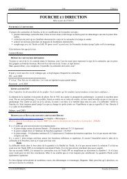
On the right, the main components of a<br />
<strong>Dell'Orto</strong> motorcycle carburetor are shown:<br />
1. starting lever; 2. air intake; 3. venturi; 4.<br />
starter jet; 5. float chamber; 6. atomizer; 7. fuel<br />
valve; 8. needle; 9. throttle valve; 10. float<br />
chamber air intake; II. fuel connection; 12. Idle<br />
mixture adjusting screw; 13. throttle valve adju-<br />
sting screw; 14. float; 15. idle emulsion tube,<br />
16.idle jet; 17. main jet.<br />
This is a diagram of the gasoline delivery in the<br />
inducted airflow: the fuel inside the float cham-<br />
ber rises in the atomizer (31), going through the<br />
jet (32) which adjusts the delivery together with<br />
the needle (28); the liquid is emulsified first<br />
with the air arriving from the channel (13) insi-<br />
de the nozzle (30) then going into the venturi<br />
(29) it mixes with the air coming from the in-<br />
take (1).<br />
basic functions:<br />
1. to control the power delivered<br />
by the engine, adjusting the<br />
airflow inducted according to<br />
driver demand.<br />
2. to meter the fuel flow into<br />
the inducted air stream, while<br />
keeping the air/fuel ratio in the<br />
optimum range over the engine's<br />
entire working range.<br />
3. to homogenize the air and<br />
fuel mixture in order to make<br />
the ignition and combustion<br />
proceed properly.<br />
THE MIXTURE RATIO<br />
The air/fuel ratio (A/F) is the ratio<br />
between the air and fuel mass inducted<br />
by the engine. It is defined<br />
as:<br />
A/F = M air/M fuel<br />
If we consider this ratio from a chemical<br />
point of view, the value of the<br />
stoichiometric A/F ratio is the one<br />
that allows complete combustion,<br />
without<br />
leaving either excess air (lean mixtures)<br />
or unburned fuel (rich mixtures)<br />
Stoichiometric A/F<br />
The stoichiometric A/F ratio depends<br />
on the fuel type. For commercial<br />
gasoline this varies from about<br />
14.5 to 14.8, meaning that 14.5-<br />
14.8 pounds of air are needed for<br />
the complete combustion of 1<br />
2
The fuel mixes with the air inducted by the engine by means of different circuits according to the throttle opening. Here above on<br />
the left hand side, we can see the operation at idle, with the liquid that is metered by the jet (18) and arrives in the fuel trap (22)<br />
before it emulsifies with the air arriving from the channel (16) and adjusted by the screw (17). This emulsion goes under the throttle<br />
valve (12) and into the aspiration channel (13) from the ports (19 and 20). On the right hand side, the same carburetor at<br />
wide open throttle with the fuel flow adjusted by the main jet (28) that it emulsifies with the air (24) in the atomizer (27) before<br />
exiting from the nozzle (26).<br />
3<br />
A modern needle type carburetor (<strong>Dell'Orto</strong> VHSB) is equipped<br />
with different circuits with relevant calibration jets to assure proper<br />
fuel delivery under all conditions. As we can see from the section<br />
diagram, each fuel circuit leads to the constant level float<br />
chamber.<br />
Section of the fuel feed circuit in a <strong>Dell'Orto</strong> VHSB carburetor: 1.<br />
Fuel line from the tank; 2. Screen filter; 3 fuel valve seat; 4 valve<br />
needle; 5 float arm pin; 6. float holder on the arm; 7. float; 8.<br />
float driver; 9. float chamber air intake.
On the left hand side above, the section of an annular float can be<br />
seen here above, used on some types of carburetors: 1. Float chamber<br />
air intake; 2. Float; 3. Fuel connection; 4. Fuel inlet channel; 5.<br />
Valve needle. In the center, a detail of a removable <strong>Dell'Orto</strong> valve;<br />
we can see that the synthetic rubber needle tip is a sprung type.<br />
Below a detail of a fuel valve, machined directly in the carburetor's<br />
body; in this case the needle is sprung.<br />
pound of fuel. For engines powered<br />
with methyl alcohol, this ratio decreases<br />
to 6.5 while for ethyl alcohol<br />
it is 9.<br />
A/F ratio produced by the carburetor<br />
The mixture delivered by the carburetor<br />
during the engine's operation<br />
doesn't necessarily correspond to a<br />
stoichiometric A/F value. According<br />
to the engine design and its operating<br />
conditions (r.p.m. and load) a<br />
portion of the delivered fuel may<br />
not be burned because it doesn't reach<br />
the combustion chamber or because<br />
the combustion itself is not<br />
perfect. Some charge dilution can also<br />
occur from residual exhaust gas<br />
remaining in the cylinder, as well as<br />
some loss of fresh charge at the<br />
exhaust. These effects are particularly<br />
sensitive in two stroke engines.<br />
If we consider that the appropriate<br />
A/F ratio must be that of the charge<br />
taking part in the combustion, we<br />
can assert that the mixture delivered<br />
by the carburetor must be richer (A/F<br />
< stoichiometric) to compensate the<br />
above phenomena.<br />
4
5<br />
A/F ratio requirement under different<br />
conditions<br />
The A/F ratio must vary within certain<br />
limits, depending on the engine<br />
operating conditions. Generally<br />
we can expect that the air/fuel mixture<br />
must be richer (A/F lower) at<br />
idle, in the acceleration mode, and<br />
at full power. On the contrary, at<br />
constant load the mixture may be<br />
lean, meaning that the A/F ratio<br />
can increase compared to the previous<br />
conditions. In two stroke engines,<br />
the words "rich" and "lean"<br />
referring to the mixture, have relative<br />
value under different specific<br />
operating conditions of the engine,<br />
and the stoichiometric mixture is<br />
not often referred to, since in these<br />
engines the mixtures are always richer<br />
that stoichiometric. This may<br />
also be partially true in many fourstroke<br />
engines, but in general, these<br />
engines use leaner mixtures than<br />
two stroke engines<br />
OPERATING PRINCIPLES OF THE<br />
BASIC CARBURETOR: THE FUEL<br />
DELIVERY CIRCUITS<br />
Liquid fuel is fed to the nozzle of<br />
the carburetor venturi, and flows<br />
due to the vacuum generated by the<br />
air flowing past the venturi itself,<br />
and from airflow pulsations generated<br />
by the piston movement. The<br />
calibrated jets placed upstream of<br />
the spray nozzle itself control the<br />
fuel flow reaching the spray nozzle.<br />
Motorcycle carburetors are nearly<br />
always of the needle type and have<br />
a structural architecture as shown<br />
in the accompanying illustrations.<br />
The fuel arriving from the tank is<br />
held inside a constant level float<br />
chamber. The liquid pressure head<br />
on the various jets is relatively constant.<br />
The difference between the<br />
float chamber fuel level and the level<br />
that the fuel must be raised to<br />
by the inducing vacuum remains<br />
constant. The float chamber level is<br />
kept constant by means of a fuel inlet<br />
valve, actuated by a float that<br />
follows free surface of the liquid in<br />
the float chamber. When the float<br />
chamber level drops, due the fuel<br />
used by the engine, the float drops<br />
and opens the valve, so that additional<br />
fuel can flow from the tank.<br />
The level of the fuel and float then<br />
increases, and at a certain point,<br />
closes the valve until the sequence<br />
is repeated. The level in the float<br />
chamber is therefore a calibration<br />
element of the carburetor, since the<br />
metered fuel delivery changes with<br />
float level, and therefore affects the<br />
mixture ratio. By having a high<br />
float level, a greater fuel quantity is<br />
delivered compared to the case with<br />
a low float level, under all operating<br />
conditions and for all of the carburetor's<br />
circuits. Adjustment of the<br />
Checking the position of the float inside the<br />
float chamber is prescribed. According to diffe-<br />
rent carburetor models, the distance of the float<br />
from the contact surface of the float chamber<br />
needs to be measured<br />
float chamber level is affected by<br />
two elements: the weight of the<br />
float (or of the floats) and the configuration<br />
of the lever arm that connects<br />
the float with the valve. By<br />
installing a heavier float, the free<br />
surface of the float chamber liquid<br />
must rise before the float buoyancy<br />
force balances the increased weight<br />
making the float rise. The result will<br />
be a higher float chamber level and<br />
a richer delivered mixture under the<br />
same conditions. On the contrary if<br />
we install a lighter float, a lower liquid<br />
level will cause sufficient<br />
buoyant force to actuate the valve<br />
and therefore the carburetor calibration<br />
will become leaner. That is<br />
why floats are classified according<br />
to their weight (printed on them)<br />
and calibration standards for their<br />
position inside the float chamber<br />
are prescribed in order to assure<br />
correct operation. To modify the<br />
float chamber level, if necessary and<br />
when it's not possible to change the
float weight, in some cases it's possible<br />
to change the angle of the lever<br />
that operates the valve.<br />
In this way, the float closes the valve<br />
in advance (for a lower level) or<br />
later (for a higher level) at equal<br />
weight.<br />
We must note, however, that too<br />
low a level in the float chamber can<br />
result in an insufficient liquid head<br />
on the jets and therefore lead to the<br />
risk of dangerous enleanment of the<br />
delivered mixture.<br />
This can occur when the fuel moves<br />
inside the float chamber due to the<br />
accelerations the vehicle undergoes.<br />
In these cases (which mainly happen<br />
on off-road motorcycles or on<br />
the track, in the bends or under violent<br />
braking), if the level is too low,<br />
one of the jets leading to the carburetor's<br />
circuits may be temporarily<br />
exposed to air instead of liquid.<br />
In some versions, special screen baffles<br />
are applied near the jets.<br />
These are called bottom traps and<br />
their purpose is to maintain the<br />
maximum liquid quantity around<br />
the jets under all possible conditions.<br />
A needle that closes on a seat,<br />
which is inserted or screwed into<br />
the carburetor's body, forms the<br />
fuel valve. The needle is equipped<br />
with a synthetic rubber element on<br />
the tip.<br />
This material is perfectly compatible<br />
with normal commercial gasoline<br />
but in the case of special fuels<br />
such as those containing alcohol, it<br />
is necessary to verify the compatibility<br />
of the fuel and the seals in order<br />
not to compromise the carburetor's<br />
functionality.<br />
Different versions of the needles are<br />
equipped with a sprung tip in the<br />
connection with the float, in order<br />
to reduce the needle's vibration induced<br />
by the motion of the liquid<br />
in the float chamber and from the<br />
motorcycle's movements.<br />
The diameter of the needle valve is<br />
a calibration element since it determines<br />
the maximum fuel delivery<br />
rate.<br />
If the diameter is too small to accommodate<br />
the fuel quantity that<br />
the engine requires under certain<br />
conditions (generally at full load)<br />
the float chamber empties faster<br />
than it can be replenished through<br />
the needle valve! If this condition<br />
should continue for some time, the<br />
Carburetors can have different types of<br />
flange connections to the engine,<br />
according to their use. On the left we can<br />
see a flat flange with a seal O-ring; on<br />
the right we see a male sleeve required for<br />
mounting inside a flexible coupling.<br />
engine suffers from reduced fuel delivery<br />
due to the fact that the level<br />
in the float chamber is decreased<br />
and therefore the carburation has<br />
become too lean.<br />
6
THE VENTURI<br />
AND THE AIRFLOW<br />
CONTROL<br />
Let's explain in detail the operation of a motorcycle's carburetor,<br />
examining the relationships between the elements which regulate fuel delivery.<br />
Motorcycle carburetors are<br />
mainly needle type with<br />
the air flow adjusted by<br />
means of a sliding valve that, depending<br />
on the different versions,<br />
can have a cylindrical or flat profile.<br />
Even in vacuum carburetors, also<br />
called at constant speed, we find<br />
such a valve that works together<br />
with the throttle valve actuated<br />
7<br />
by the driver. We will talk about<br />
these carburetors later on due to<br />
their peculiar working features.<br />
THE VENTURI<br />
The venturi is one of the elements<br />
that define the carburetor, since a<br />
basic dimension is the diameter of<br />
the venturi itself, generally expressed<br />
in mm.The diameter choice<br />
is strictly related to the engine<br />
requirements, which must be<br />
satisfied.<br />
For motorcycle engines, a separate<br />
carburetor feeds each cylinder;<br />
therefore the problem of flow distribution<br />
from a single carburetor<br />
to different cylinders is<br />
avoided.<br />
From a numerical point of view<br />
the critical dimensions are selected
The venturi of the modern motorcycle carburetor is carefully developed to redu-<br />
ce disturbances in the flow around the throttle valve and its seat.<br />
On the left-hand side, we see the venturi fitted on a <strong>Dell'Orto</strong> VHSD carbure-<br />
tor with two thin slits where the guillotine runs to adjust the airflow.<br />
Below, left hand side the section of a VHSB carburetor where the reduced<br />
thickness of the flat throttle is emphasized. On the right is the cylindrical valve<br />
of a carburetor series PH, showing a dimension in the flow direction, higher<br />
than in the first case. In both drawings we can see, under the venturis, the pas-<br />
sages which lead to the idle and progression circuits, which we will discuss la-<br />
ter in this article.<br />
according to constructive practice<br />
and from the experience accumulated<br />
on a wide range of motorcycles<br />
and engine types.<br />
The diameter determination is<br />
then made through tests on the<br />
engine.<br />
For instance, small two-stroke en-<br />
8
gines used in cycles and scooters<br />
are equipped with carburetors having<br />
a venturi with a diameter<br />
from 12 to 14mm.On 125cm 3 displacement<br />
two stroke engines<br />
used in competition, we use venturis<br />
with diameters which can<br />
vary from 36 up to 40 mm and<br />
over, as is common on powerful<br />
rotary valve units used in racing.<br />
When performance is the main<br />
consideration, the venturi diameter<br />
determines the resistance that<br />
the aspiration system (the carburetor's<br />
venturi is part of this system)<br />
offers to the aspirated flow.<br />
Large diameter venturis obviously<br />
introduce a lower resistance than<br />
we usually have with smaller diameter<br />
venturis, therefore in order<br />
to improve the efficiency of this<br />
component, inserts inside the<br />
venturi itself are used, which eliminate<br />
steps and shape variations,<br />
while keeping the diameter<br />
value.<br />
The inserted venturis of <strong>Dell'Orto</strong><br />
VHSB series carburetors are shown<br />
in the illustrations.<br />
On the contrary, a venturi with<br />
reduced diameter results in higher<br />
air speed at an equal flow induc-<br />
9<br />
Shown above are two different shapes of the venturi's opening. On the<br />
left we have the classic oval section while on the right the one called<br />
"badge (shield)" which shows a smaller area portion on the lower side,<br />
close to the small fuel ports that results in better modulation as requi-<br />
red by some engine types.<br />
Below, a comparison between a round piston throttle valve and a plane<br />
valve, also called guillotine. In the center we have the guiding hole for<br />
the conical needle.
Above, on the left: valves often have a hardened surface<br />
with chrome plating in order to assure high resistance<br />
to wear. The shape of both edges is very important to<br />
assure there is no leakage when the valve is closed. On<br />
the right is a valve introduced in the insert-venturi that<br />
is assembled in the carburetor's body (<strong>Dell'Orto</strong> VHSB)<br />
Below, the valve and spring assembly of a competition<br />
<strong>Dell'Orto</strong> VHSD carburetor. The spring is of small di-<br />
mensions, but sufficient to shut off the airflow, thanks<br />
to the low friction of the sliding guillotine.<br />
ted by the engine and, therefore,<br />
results in a higher vacuum signal<br />
on the nozzles which deliver the<br />
fuel.<br />
In some conditions and for engines<br />
that have to work over a wide<br />
range of r.p.m., such a feature can<br />
become very important, with less<br />
consideration to the need for<br />
lower resistance.<br />
On this matter we can assert that<br />
the power loss introduced by the<br />
carburetor depends, in addition<br />
to the diameter of its venturi, on<br />
its profile in the direction of the<br />
airflow.<br />
Beyond the configuration of the<br />
throttle valve area, the connections<br />
with the air intake and the<br />
area downstream of the venturi,<br />
where the carburetor connects<br />
with the aspiration channel, are<br />
very important.<br />
THE SHAPE OF THE VENTURI<br />
SECTION<br />
Once the area is determined, according<br />
to the supply requirements<br />
of the engine, there are design<br />
choices to be made on the<br />
shape of the venturi section.<br />
For competition engines or engines<br />
which have to offer high<br />
performance without any particular<br />
concern regarding other operating<br />
modes, the most favorable<br />
section with regard to power loss<br />
10
11<br />
is the round section, since it has<br />
the minimum perimeter (at equal<br />
areas) to resist inducted flow.<br />
For engines which have to provide<br />
a smooth modulation of<br />
power, we use generally carburetors<br />
with a venturi having an extended<br />
shape section, called<br />
"oval" or even a more complex<br />
shape such as the one <strong>Dell'Orto</strong><br />
engineers called "badge (shield)"<br />
and which represents an evolution<br />
of the concept of the oval<br />
section venturi. As we have seen,<br />
a small diameter venturi improves<br />
the engine's responsiveness, since<br />
it keeps the flow velocity high.<br />
An oval venturi presents a smaller<br />
section, because it has a reduced<br />
diameter when the throttle valve<br />
is lifted slightly.<br />
At small openings, then, the carburetor<br />
behaves as it had a reduced<br />
diameter.<br />
This provides a good solution to<br />
transient operation and wide<br />
power range, and gives a good relationship<br />
of proportionality<br />
between the driver's action and<br />
response in terms of delivery<br />
from the carburetor. When the<br />
throttle opening increases, the<br />
shape of the venturi section recovers<br />
the area necessary to aspirate<br />
the flow without introducing any<br />
high fluidynamic resistance. The<br />
badge (shield) venturi has a triangular<br />
shape at small throttle openings,<br />
and therefore in this region,<br />
the opening area is very reduced,<br />
to enhance the features of<br />
The throttle valve of "needle" carburetors has a chamfered ed-<br />
ge (measured in tenths of mm: for example, .30) which in-<br />
fluences the carburation at small throttle openings. A valve<br />
with low chamfer (as above) enriches the mixture up to 1/4<br />
throttle, while if the carburation is too rich, we can use a val-<br />
ve with a higher chamfer (as below).<br />
The influence of this calibration element is mainly in tran-<br />
sient operation at small throttle openings and even limited<br />
changes (i.e. from .30 to .40) may strongly influence the deli-<br />
vered mixture.<br />
response which are necessary on<br />
some kinds of engines with automatic<br />
transmissions.<br />
THROTTLE VALVE<br />
In traditional non-vacuum carburetors,<br />
this is the adjustment<br />
component connected to the accelerator<br />
by means of a flexible<br />
cable.<br />
This valve slides transversely to<br />
the venturi determining the effective<br />
area of the flow passage.<br />
In different carburetor models<br />
(such as <strong>Dell'Orto</strong> series PH, where<br />
P means "Piston" referring to<br />
the valve, and H means "Horizontal"<br />
referring to the channel<br />
orientation), the valve is a cylindrical<br />
element which slides with<br />
very little clearance in a seat, machined<br />
into the carburetor's body.<br />
In other versions (<strong>Dell'Orto</strong> series<br />
VH, where V means "valve") the<br />
element is plane, with driving<br />
flyers or rounded edges developed<br />
to reduce air leakage, as for example<br />
in <strong>Dell'Orto</strong> VHSD.<br />
For carburetors used in 4 stroke<br />
engines, the vacuum in aspiration,<br />
at closed position, can reach<br />
extremely high values and keep<br />
the valve pressed against its seat.<br />
In order to eliminate wear (and<br />
therefore leakage) and sticking,<br />
these components undergo surface<br />
treatments which improve the<br />
hardness of the material and operating<br />
smoothness, similar to chromed<br />
brass valves.
Together with these designs, some<br />
slightly stiff return springs are<br />
used, in order to assure a positive<br />
return to the closed valve position.<br />
However, since the stiffness of the<br />
spring determines the opening<br />
effort from the driver, it's a good<br />
rule to choose valves which slide<br />
more smoothly before increasing<br />
the return spring force.<br />
The valves called "plane" reduce<br />
the turbulence affecting the air<br />
flow that goes under the valve itself<br />
since this design provides a<br />
shorter impediment in the direction<br />
of the flow itself.<br />
Even for this kind of valve we must<br />
carefully understand all the issues<br />
related to sealing at the closed<br />
condition, providing surfaces<br />
with chrome plating to reduce<br />
wear.<br />
The advantages we gain in terms<br />
of deflection of the flow path<br />
with a reduced width valve are<br />
however counterbalanced by the<br />
need to solve the problem of location<br />
of the progression holes.<br />
These holes are needed to deliver<br />
fuel when the throttle opening<br />
changes, during the progressivetransition<br />
from operation of the<br />
idle circuit to the main one and<br />
vice-versa.<br />
These holes are machined downstream<br />
the main atomizer, but in<br />
order to work, as we will see later<br />
on, they have to be below the throttle<br />
valve edge.<br />
If the valve is very tight, these<br />
holes will obviously be very close<br />
to the main atomizer (also located<br />
under the valve) making the<br />
design approach more complex.<br />
Once it has been solved, however,<br />
this design will assure the best<br />
functionality.<br />
Some of the carburetors <strong>Dell'Orto</strong> has developed<br />
for modern, small displacement<br />
motorcycles.<br />
In this case, some tricks have been in this<br />
case adopted: elaborate shape venturis<br />
and automatic starting circuit, which<br />
provide for the best operation of the engine<br />
under all conditions.<br />
12
THE IDLE CIRCUIT<br />
AND THE<br />
PROGRESSION<br />
Manufacture and operation of two very important systems, which allow the practical use<br />
of a carburetor for motorcycles<br />
We have seen how in a "basic"<br />
(simplified) carburetor,<br />
the fuel is drawn into<br />
the venturi from the float chamber.<br />
This occurs as a result of the vacuum<br />
created by the airflow, which passes<br />
through the venturi, drawn by the<br />
engine itself.<br />
In reality, a modern carburetor comprises<br />
more than a fuel supply system,<br />
since using only the main circuit<br />
the correct delivery of fuel could<br />
not be obtained (and therefore a correct<br />
mixture ratio) at all possible<br />
operating conditions that occur during<br />
the practical use of an engine.<br />
The working principles of each of<br />
the auxiliary systems stems from the<br />
same physical principle. The principle<br />
is that the fuel responds to a vacuum<br />
signal generated by the induction<br />
action of the engine.<br />
The auxiliary systems are, however,<br />
separated from one another, because<br />
the supplying nozzles are located in<br />
places appropriately designed into<br />
the carburetor's venturi.<br />
THE IDLE CIRCUIT<br />
When the throttle valve is closed,<br />
or nearly completely closed, the inducted<br />
air flow which draws on the<br />
main spray nozzle is very low, and<br />
therefore is not sufficient to draw<br />
fuel from the float chamber. For<br />
this reason the carburetor is equipped<br />
with a second supply circuit<br />
which comes into play in these circumstances<br />
(at idle, precisely) allowing<br />
the engine to operate normally.<br />
If it were not for the idle circuit,<br />
the engine would stop running,<br />
even in the transition stages<br />
13
Below, with the throttle valve partially lifted, we can notice<br />
the arrangement of the progression port.<br />
Above are two details of the supply ports of the idle and pro-<br />
gression circuits, which can be seen slightly downstream of<br />
the main spray nozzle.<br />
We can notice how the progression port is always placed be-<br />
low the throttle valve and that its distance from the main<br />
nozzle depends on the shape of the valve itself (cylindrical,<br />
on the left, or flat on the right).<br />
when the driver starts to open the<br />
throttle.<br />
The idle circuit is equipped with a<br />
supply port placed immediately<br />
downstream of the throttle valve, at<br />
a point such that once the valve is<br />
closed, it experiences strong vacuum<br />
conditions and therefore is in<br />
the best condition to supply fuel<br />
from the float chamber.<br />
The duct, which leads to this port,<br />
connects with a proper jet (idle),<br />
that permits calibration of the idle<br />
fuel flow.<br />
During calibration, the choice of idle<br />
jet is very important not only for<br />
the operation in this condition, but<br />
also for the engine response during<br />
transitions, since even the progression<br />
stage is affected by the idle jet,<br />
in addition to the other calibration<br />
elements such as the chamfer of the<br />
throttle valve or the needle nozzle<br />
fit, and when present, the small<br />
milling performed on the edge<br />
downstream of the valve, or even<br />
the projection (the engineers call it<br />
"stake"), that projects in this same<br />
area, whose functions are explained<br />
in the relevant pictures.<br />
14
PROPER SELECTION OF THE ID-<br />
LE JET<br />
Generally, if the selected idle jet is<br />
too big, the engine may tend to stall<br />
and responds to the accelerator<br />
slowly with a deaf and feeble sound,<br />
usually overcome by closing the throttle<br />
temporarily.<br />
If, on the contrary, the jet is too<br />
small, the engine responds better to<br />
the accelerator (except when it stalls<br />
when the jet is much too small), but<br />
when the throttle is closed, the<br />
speed (rpm) doesn't decrease immediately,<br />
and the speed remains high<br />
for few seconds before settling down<br />
to idle.<br />
Installation of an idle jet that is too<br />
small on a two stroke engine can be<br />
dangerous since there is the risk of<br />
engine seizure during throttle closing,<br />
especially when the engine has<br />
run at wide open throttle for a long<br />
time. Under these conditions, when<br />
the throttle closes, the engine keeps<br />
on running at high speed and therefore<br />
if the idle circuit creates too<br />
lean a mixture, the thermal load due<br />
to the overly lean combustion presents<br />
the risk of damage the engine<br />
from overheating and subsequent<br />
seizure.<br />
THE EMULSION AIR CIRCUIT<br />
The fuel supplied by the idle circuit<br />
is mixed with a small quantity of air<br />
(thanks to a diffuser expressly placed<br />
for that purpose) that flows into<br />
the fuel passage (liquid) from the<br />
idle air channel. From there, the<br />
passage leads to the progression<br />
15<br />
On the left, a throttle valve with a notch on the rear edge. In the center,<br />
two valves with a "stake" needed to interact at different modes the<br />
progression circuit.<br />
Below, two possible locations for the idle jets are shown. The calibration<br />
element can be single and machined into the emulsion tube, or it can be<br />
formed by two separated elements, where the second is the emulsion tu-<br />
be, or an emulsion jet that works in series with the first one to keep a hi-<br />
gher quantity of liquid on the calibrated passage.
On the left, the idle jet, whether or not connected to a diffuser, is often<br />
screwed inside the emulsion tube and not outside as is common in other<br />
versions of carburetors.<br />
On the right, the illustration of the idle circuit of a <strong>Dell'Orto</strong> VHSB<br />
carburetor, with the air adjustment by means of a screw. In the section we<br />
note the progression passage immediately below the throttle valve.<br />
port. This progression port is placed<br />
upstream of the rear edge of the valve,<br />
just before the idle port (with respect<br />
to the direction of the airflow<br />
in the diffuser).<br />
When the idle circuit is working, a<br />
small quantity of air is inducted by<br />
this port, and bypasses the valve<br />
(which is quite completely closed)<br />
and mixes with the fuel supplied by<br />
the jet. As the valve lifts, the contribution<br />
of this element decreases<br />
as far as the idle circuit is concerned,<br />
while it becomes important for<br />
the progression circuit.<br />
The other air flow comes directly<br />
from the carburetor's mouth where<br />
it's previously controlled by a calibrated<br />
passage that, in some models,<br />
can be removable and takes<br />
the shape of an actual jet, sometimes<br />
called "idle air break".<br />
THE IDLE AIR AND MIXTURE<br />
ADJUSTMENT SCREWS<br />
The fine adjustment, while setting<br />
up, is done by means of the idle air<br />
screw with a conical tip that modulates<br />
the passage in the idle air<br />
channel.<br />
Some carburetor models are, on the<br />
contrary, equipped with a mixture<br />
adjusting screw which intervenes<br />
on the fuel and airflow already<br />
emulsified and directed to the delivery<br />
port.<br />
As the idle air screw adjusts only<br />
the air, while the mixture adjustment<br />
acts on the fuel flow, we have<br />
to operate them in the opposite<br />
manner according how the carbure-<br />
16
Here above we see two of the same model of carburetors, but with<br />
two different idle circuit adjustment systems. The one on the right<br />
is equipped with an air adjustment screw, while the one on the left<br />
has a mixture adjustment screw, recognizable because it is placed<br />
on the engine side and on other carburetors with the mixture adju-<br />
stment screw placed soon before the engine sleeve connection.<br />
tor is equipped. To enrich we have<br />
to close the air screw (by closing the<br />
airflow) or open the mixture screw.<br />
To lean the mixture, one has to<br />
open the air screw or close the mixture<br />
screw.<br />
The elements are easily recognizable<br />
on the carburetor since the air<br />
adjustment screw is placed by the<br />
front plug, which connects to the<br />
filter, while the mixture screw is<br />
placed on the side towards the engine.<br />
TRANSITION CIRCUIT<br />
When the driver starts to open the<br />
accelerator, the throttle valve lifts<br />
and therefore decreases the vacuum<br />
that in the closed condition, activa-<br />
17
On the left side we see a VHSC with the air adjustment screw near the<br />
aspiration mouth.<br />
On the right, the air adjustment screws (the two on the left) have a smal-<br />
lerpoint than the mixture screws (on the right) since they are required to<br />
control a different fluid and therefore allow a finer adjustment. By<br />
controlling the air, this system has its own influence on the progression<br />
circuit, while the mixture screw acts only on the idle delivery.<br />
ted the idle circuit.<br />
The delivery of fuel from the idle<br />
circuit is reduced, and therefore it is<br />
necessary to introduce another system,<br />
which is able to handle the<br />
transition of functions from the idle<br />
circuit to the main circuit.<br />
We described above the progression<br />
system as far as the idle air contribution<br />
is concerned.<br />
When the valve is lifted slightly (up<br />
to about 1/4 throttle) the vacuum<br />
generated by the inducted airflow<br />
begins to be consistent, and stops<br />
drawing fuel from the idle nozzle.<br />
Under these conditions, the vacuum<br />
is sufficient; however, to<br />
draw fuel from the progression<br />
port, which is always fed by the idle<br />
jet placed in the float chamber.<br />
It's clear then, how the progression<br />
port is traversed first by air that<br />
goes towards the idle circuit, and later,<br />
while the throttle is opened<br />
partially, is traversed in the opposite<br />
direction by a fuel flow (or better,<br />
of air/fuel emulsion coming from<br />
the idle circuit). This explains the<br />
importance of the idle jet, even in<br />
the first stages of throttle opening.<br />
The position of the progression<br />
port, between the main and idle<br />
nozzles, is very important for the<br />
correct operation of the carburetor<br />
and is the subject of careful development.<br />
18
19<br />
THE MAIN<br />
CIRCUIT<br />
Operation layout and guideline for setting the main delivery system of the<br />
carburetor<br />
Modern carburetors used on<br />
motorcycle engines are defined<br />
as "needle type"due<br />
to the mechanical configuration of<br />
the main delivery system. The tapered<br />
needle assures the correct mixture<br />
ratio for all operating conditions<br />
of the engine corresponding<br />
to openings of the accelerator from<br />
1/4 up to wide open throttle.<br />
THE TAPERED METERING ROD<br />
As usual, the fuel is drawn into the<br />
venturi from the vacuum generated<br />
by the induced airflow, but from<br />
the moment that the throttle valve<br />
closes, the same vacuum changes<br />
within very wide limits. For small<br />
throttle openings the engine vacuum<br />
level is generally higher than<br />
when the valve is partially or fully<br />
lifted and subsequently, the fuel de-<br />
livery from the nozzle of the main<br />
circuit changes proportionally.<br />
By responding only to the vacuum<br />
signal, a main circuit comprised of<br />
only the nozzle would deliver a lot<br />
of fuel at small and intermediate throttle<br />
openings, maintaining a rich<br />
mixture strength. At large openings,<br />
the delivery would decrease at the<br />
worst time, risking engine damage<br />
from a lean mixture.<br />
The basic calibration elements of a carburetor. A: Throttle valve;<br />
B: Float; C: Atomizer; D: Main Jet; E: Idle Jet; F: Tapered Needle;<br />
G: Starter Jet.<br />
A<br />
D<br />
C<br />
E<br />
F<br />
B<br />
G
That is why the system with a conical<br />
needle has been adopted, with a<br />
configuration well known to<br />
everyone and clearly visible in the<br />
illustrations.<br />
The needle runs inside the metering<br />
section of the atomizer, and when<br />
the valve is lifted only slightly, the<br />
passage available for the fuel is<br />
small.<br />
As a result, in spite of the high vacuum,<br />
the delivery is low and therefore<br />
the mixture ratio is generally<br />
correct.<br />
At wide throttle openings, the smaller<br />
diameter conical part of the<br />
needle reaches the atomizer and<br />
therefore increases the passage area.<br />
It is true that the vacuum, within<br />
certain limits, is decreased but the<br />
increase in the available area of the<br />
fuel metering passage keeps the<br />
mixture ratio at optimum value<br />
and, therefore, the engine is able to<br />
run properly all throttle openings.<br />
Once the operating principle is<br />
clear, it becomes simple to understand<br />
the adjustment of the conical<br />
needle system, which involves two<br />
adjustment elements; the needle itself<br />
and the calibrated section of the<br />
atomizer.<br />
In <strong>Dell'Orto</strong> carburetors the needle<br />
Above, the group of main and starting<br />
jets inside the float chamber. We can<br />
note the baffle that keeps fuel in the<br />
chamber of the main jet even when<br />
the motorcycle is subjected to accelera-<br />
tion that would tend to move the li-<br />
quid mass in the float chamber.<br />
Below, the conical needle and atomi-<br />
zer placed in their relative working<br />
positions.<br />
20
Two photos of the 4-stroke atomizer: Above, the ato-<br />
mizer mounted inside the nozzle that keeps it in the<br />
carburetor's body; below some atomizers (all<br />
having the same shape and diameter of the calibra-<br />
ted hole, but with different drilling of the tube.<br />
is fixed in the valve by means of a<br />
spring clip which engages in one of<br />
the notches on the rod. Conventionally,<br />
the notches are numbered<br />
starting from the top.<br />
Attaching the clip in the higher<br />
notches, the needle (relative to the<br />
atomizer) is lower; meaning that to<br />
reach the conical area, the valve has<br />
to be lifted more. Conversely, if we<br />
wish to introduce the arrival of the<br />
conical zone earlier in the throttle's<br />
travel, we have to lift the needle,<br />
attaching the clip to the lower notches<br />
(second, third and so on).<br />
Practically, if at equal opening of<br />
the accelerator there is the need to<br />
lean the mixture, we have to lower<br />
the needle moving the clip towards<br />
the top, while if the engine has carburation<br />
which is too rich (slowness<br />
in reaching the correct r.p.m. and<br />
dull and deep sound) we have to<br />
lower the needle, placing the clip in<br />
the higher notches.<br />
The variables introduced from the<br />
shape of the needle, (meaning its<br />
taper ratio and the length of its conical<br />
section) are absolutely essential<br />
for the carburation calibration<br />
since they have a strong influence<br />
on the general response of the engine.<br />
Very often, however, it is not possible<br />
to correctly adjust the carburetor<br />
by modifying only the needle<br />
position and, therefore, it becomes<br />
necessary to replace it with another<br />
part with different features.<br />
For each family of carburetors,<br />
<strong>Dell'Orto</strong> has a wide range of conical<br />
needles with different dimen-<br />
21
sions as we can see in the attached<br />
table. According to the needs which<br />
may arise during adjustment, we<br />
select the necessary needles and<br />
proceed with testing.<br />
If, for example, we can not manage<br />
to get sufficient enrichment in a<br />
certain area by lifting the needle to<br />
its highest position, it's clear that<br />
we will have to install one with the<br />
same taper (it's always better to introduce<br />
just one variable at a time)<br />
On this page we see two stroke type atomi-<br />
zers: above on the left a view from the top of<br />
the nozzle that surrounds the actual atomizer<br />
on the right.<br />
Below are four different configurations of the<br />
step that projects inside the venturi.<br />
Below on the right, the atomizers may be re-<br />
cognized by the height of the edges and by the<br />
dimension of the hole where the conical need-<br />
le operates.<br />
but with the conical part starting<br />
higher on the rod.<br />
Different needles are installed having<br />
a conical area with different<br />
tapers to better match the needs of<br />
various engines.<br />
THE METERING ROD AND<br />
ATOMIZER<br />
The atomizer end closest to the<br />
venturi contains the calibrated dia-<br />
meter.<br />
This component is available in various<br />
dimensions.<br />
By increasing the atomizer's diameter,<br />
the mixture is enriched, while it<br />
will be the contrary when the diameter<br />
is decreased. Obviously we<br />
can get the same effect by changing<br />
the calibrated diameter the conical<br />
needle, at the expense of some<br />
other of its features. Sometimes a<br />
needle with the appropriate diame-<br />
22
23<br />
ter in the conical area is not readily<br />
available.<br />
In this case it's much easier, once<br />
the need has been established, to<br />
replace the atomizer, even though<br />
<strong>Dell'Orto</strong> carburetors are supplied<br />
with calibrations already optimized<br />
according to the category of the engine<br />
where they will be used. The<br />
calibration will probably an adjustment<br />
of the jets, the position, and<br />
eventually of the conical needle type<br />
while, generally, the atomizer<br />
and the valve chamfer don't require<br />
any change even though spare parts<br />
are available for most models.<br />
THE ATOMIZER AND ITS EMUL-<br />
SION HOLES<br />
The atomizer, in its simplest shape,<br />
is a tube that connects the main jet<br />
to the venturi.<br />
For this element there are two possible<br />
configurations that, traditionally,<br />
the engineers call "two stroke<br />
type" or "four stroke type".<br />
Some have with a series of holes<br />
placed along the whole area and in<br />
communication with the main circuit<br />
channel (four-stroke type).<br />
ATOMIZER DESIGN FOR TWO-<br />
STROKES<br />
The atomizer is screwed into the delivery<br />
nozzle fitted in the carburetor's<br />
body.<br />
As we can see in the illustration, the<br />
edge of the tube projects inside an<br />
annular chamber open to the venturi<br />
and at the same time in communication<br />
with the air intake by<br />
means of the main area channel.<br />
Due to the vacuum in the venturi<br />
then, from the atomizer tube the liquid<br />
fuel is drawn, metered by the<br />
main jet and by the conical needle,<br />
while a certain airflow is delivered<br />
from the channel, going into the<br />
The main circuit is also supplied with<br />
air that goes to emulsify the fuel in the<br />
atomizer (four-stroke) or in the nozzle<br />
(two-stroke). The main emulsification<br />
air intake is usually placed in the main<br />
plug on the carburetor's mouth, as we<br />
see in this picture. The second hole is<br />
for idle emulsion air.<br />
annular chamber.<br />
In this area air and fuel are mixed<br />
together forming a finely atomized<br />
spray inducted by the engine.<br />
In addition to the atomizer's hole<br />
diameter, the variables are therefore<br />
the diameter of the air channel (by<br />
increasing it, the mixture leans), the<br />
height of the atomizer's side that<br />
projects in the chamber and the<br />
"step" of the delivery nozzle that<br />
projects into the venturi.<br />
Let's start with the atomizer.<br />
Under the same conditions, if the<br />
edge is short, the fuel has to travel a<br />
shorter distance from the float<br />
chamber and therefore the delivery<br />
will be more immediate. The "low"<br />
atomizer is as a matter of fact a typical<br />
feature of competition motorcycle<br />
carburetors.<br />
If, vice versa, the atomizer is high,<br />
the mixture will be leaner in acceleration.<br />
The same is true for the step in the<br />
venturi. This creates an impediment<br />
to the airflow inducted by the engine<br />
and therefore downstream of it<br />
there is a strong vacuum area, which<br />
activates the delivery of the circuit.<br />
By increasing the step, such vacuum<br />
increases and therefore the<br />
mixture enriches, while using a carburetor<br />
with a lower step, we can<br />
get leaner deliveries.<br />
ATOMIZER DESIGN FOR FOUR-<br />
STROKES<br />
This system is presently widely used<br />
in two stroke engines, since it permits<br />
leaner and better-controlled<br />
mixtures under all conditions.<br />
The atomizer tube is equipped with<br />
a series of holes and the annular<br />
chamber that surrounds it is always<br />
in communication with the main<br />
area, but not in direct communication<br />
with the venturi.<br />
The air is then mixed together with<br />
the liquid fuel and the emulsion is<br />
done inside the tube, before the<br />
mixture reaches the nozzle in the<br />
venturi, which for this reason has<br />
no steps.<br />
The arrangement of the holes and<br />
their diameter influences the delivery.<br />
Holes machined in the lower part of<br />
the atomizer are bathed in the fuel<br />
of the float chamber, while the holes<br />
in the upper part are exposed to<br />
the air.<br />
Subsequently, by working with the<br />
variables of the drilling one can manage<br />
to optimize the mixture ratio<br />
under all conditions.<br />
When the upper drilling is preferred,<br />
the mixture is made leaner,<br />
while if we increase the number<br />
and/or the diameter of the lower<br />
holes, the flow of fuel increases and<br />
goes to emulsify itself with the air.<br />
The drilling even influences the<br />
transition in acceleration, since by<br />
placing the holes at a different height,<br />
the annular chamber is full of<br />
fuel at the start of a transition, and<br />
empties when the speed increases<br />
due to the liquid drawn through<br />
the same holes. In this way, the delivery<br />
starts with a very rich mixture<br />
and then becomes leaner.
THE MAIN JET<br />
The basic element of the carburetor's<br />
adjustment, at full power and<br />
for wide throttle openings, is the<br />
main jet, which controls the calibration<br />
of fuel delivered from the main<br />
system.<br />
The main jet is mounted in the<br />
lowest part of the float chamber to<br />
ensure that it is always covered with<br />
liquid, even when the motorcycle<br />
makes excessive maneuvers.<br />
In many cases, to ensure the presence<br />
of liquid fuel, a perforated baffle<br />
is installed that keeps a proper<br />
quantity of liquid fuel around the<br />
jet.<br />
The choice of main jet has a strong<br />
influence on the performance of the<br />
engine and is selected experimentally.<br />
It's therefore better to start by<br />
mounting a larger jet with respect to<br />
the engine requirements to work safely.<br />
A rich carburation doesn't produce<br />
the best performance, but at least<br />
there is no risk of damage the engine<br />
by performing tests with overly<br />
lean carburation (seizure or piston<br />
drilling).<br />
We proceed by attempts, performing<br />
bench tests and/or acceleration<br />
tests.<br />
After a run at wide-open throttle at<br />
maximum rpm the spark plug appearance<br />
can help to determine the<br />
best calibration choice. The insulator<br />
of the central electrode must be<br />
light brown.<br />
If it's darker, the jet is too big, if it's<br />
clear, quite white; the jet is too<br />
small. To "read" the central insulator,<br />
the spark plug must have run<br />
for a long time, while examining<br />
the ground electrode it's possible to<br />
work with a new spark plug. The<br />
root of the electrode towards the<br />
spark plug housing should be at least<br />
half-black next to the bend in the<br />
electrode itself; the rest should be a<br />
natural metalcolor.<br />
If the ground electrode is all black<br />
and sooty, the carburation is rich,<br />
while on the contrary if we find it<br />
perfectly clean, the main jet is too<br />
small with the risk of heavy damage<br />
to the engine.<br />
After having chosen the proper jet,<br />
If we are not using a competition<br />
motorcycle, it's better to increase<br />
the jet by two or three sizes as a<br />
precaution and for protection in case<br />
of possible calibration drift induced,<br />
for example, by temperature<br />
changes.<br />
When we use very big jets, it's better<br />
to check with a simple calculation<br />
that the passage area of the jets<br />
doesn't become smaller than the<br />
one (of an annulus) created by the<br />
tip of the conical needle inside the<br />
atomizer.<br />
The following relationship must occur<br />
so that the main jet is always in<br />
control of the fuel supply. We have<br />
to remember, however, that this jet<br />
has an important role in acceleration,<br />
when the driver suddenly<br />
opens the throttle and the main circuit<br />
(needle and well of the atomizer)<br />
must start working quickly.<br />
The fuel that feeds the system, as a<br />
matter of fact, is calibrated from the<br />
main jet.<br />
At this moment, what is called<br />
"lean peak" occurs, meaning that in<br />
the first moment of throttle opening<br />
the carburation leans, to return<br />
soon after to the optimal value<br />
(rich) necessary for the operation of<br />
the engine.<br />
To eliminate the influence of pressure pulses pre-<br />
sent in the filter box, sometimes the main emul-<br />
sion air inlet is drawn from the outside by means<br />
of a connection in which we see the feed tube on<br />
the right of the carburetor. In this case the hole<br />
in the air intake is plugged.<br />
24
25<br />
THE CARBURETOR:<br />
THE ADDITIONAL<br />
SYSTEMS<br />
From the acceleration pump to the power jet: the special configuration of circuits that<br />
apply to some carburetor models<br />
As stated in the previous article,<br />
a carburetor would be<br />
able to run perfectly if it had<br />
only the idle, progression and main<br />
circuits, since the fuel delivery<br />
would be properly proportioned to<br />
all the engine's requirements. What<br />
is missing from these features,<br />
however, is the cold starting stage,<br />
when thermal conditions make it<br />
necessary to provide a richer mixture<br />
than the usual one, delivered by<br />
an appropriate circuit called the<br />
starting circuit or starter device. All<br />
carburetors have it, except for some<br />
particular models used on competition<br />
motorcycles where the starting<br />
procedure is something special.<br />
Additionally, specific delivery systems<br />
have been developed for<br />
other needs, in order to allow a correct<br />
response to the peculiar features<br />
of some types of engines: we have<br />
therefore acceleration pumps for<br />
some 4 stroke engines and a power<br />
jet for some 2 stroke engines.<br />
THE STARTER DEVICE.<br />
When the engine is cold and the<br />
outside air temperature is rather<br />
low, some of the air/fuel spray delivered<br />
by the carburetor nozzles<br />
does not reach the thermal unit<br />
(combustion chamber), since part of<br />
it condenses and settles on the cold<br />
walls of the aspiration channel. For<br />
this reason, the effective mixture<br />
strength that feeds the engine is often<br />
too lean and therefore there might<br />
be some combustion problems<br />
that cause starting difficulties (the<br />
engine doesn't start) or in the best<br />
cases, operating irregularities and<br />
Illustration of the starting circuit of a <strong>Dell'Orto</strong> VHSB carburetor: the circuit is opened<br />
and closed by a valve 16 actuated by means of lever 17; the fuel is delivered in chan-<br />
nel 14 from the nozzle 15, after emulsification with air coming from channel 11 insi-<br />
de the atomizer 13. The starting jet is n° 12.
On the left, the starting system with automatic starter is shown. The<br />
fuel drawn by the jet 10 mixes with the air coming from the channel 6,<br />
inside of the emulsion tube 9 and reaches the channel 8 controlled by<br />
the valve with the conical needle 7, linked up to the electric actuator.<br />
On the right, in a section of the <strong>Dell'Orto</strong> automatic starter we see an<br />
electrical winding that warms the thermally sensitive element, that<br />
then gradually closes the needle of the circuit.<br />
Below, a starting jet that incorporates an emulsion tube, where the air<br />
passes through holes placed near the threads.<br />
bad driveability, until the engine<br />
warms up to a normal operating<br />
temperature.<br />
The carburetors are equipped with a<br />
starting circuit, completely separated<br />
from an operating point of view<br />
from the other delivery systems,<br />
and designed to correctly enrich the<br />
mixture.<br />
This is provided in order to allow<br />
that even if part of the fuel from<br />
the other circuits doesn't reach the<br />
engine, the addition of fuel from<br />
the starting circuit is sufficient for<br />
starting, and for maintaining regular<br />
operation in the first minutes of<br />
running.<br />
The simplest system is the manual<br />
rich mixture control, sometimes<br />
called "primer" or "mixer" and currently<br />
used only occasionally because<br />
more refined configurations<br />
are available.<br />
The mixer consists of a switch, or<br />
lever, that allows the driver to manually<br />
lower the float in the float<br />
chamber, thereby raising the fuel level.<br />
As a consequence, the carburation<br />
is enriched under all conditions<br />
and then it may be returned<br />
to the normal position after the engine<br />
has been started.<br />
Since this system requires the operator<br />
to control the mixer, the efficiency<br />
of the system is dependent<br />
on the driver's experience and, in<br />
addition, the carburetor must be<br />
physically accessible on the motorcycle.<br />
There are more refined and functional<br />
starter circuits equipped with<br />
their own channel, with a jet and<br />
26
27<br />
with a flow control device. These<br />
can be a small piston valve manually<br />
actuated by the driver (directly,<br />
or through a flexible cable) or can<br />
be controlled automatically by an<br />
electric actuator by means of a thermo-sensitive<br />
element. These actuators<br />
are called "wax motors" due to<br />
the heating of wax produced by an<br />
electric circuit.<br />
The wax expands when heated, moving<br />
the valve of the starter circuit<br />
Since thermal expansion is a function<br />
of the initial temperature, it's<br />
clear how the adjustment of these<br />
circuits is completely automatic and<br />
adapts itself to the temperature at<br />
which the engine is started, and to<br />
the rate at which the engine warms<br />
up once operating.<br />
Whether the valve is opened or closed,<br />
and controlled by an automatic<br />
The acceleration pump fitted on a PHF carburetor and below, the same<br />
disassembled: we see the actual diaphragm pump and the lever system that<br />
is actuated by the inclined profile (cam) introduced in the Valve.
Above, the nozzle spraying fuel into the venturi is controlled by a calibrated hole<br />
machined into the body of the nozzle itself. This component is kept in the seat by a<br />
plug (cap), therefore in <strong>Dell'Orto</strong>'s carburetors it is easy to reach from the outside.<br />
Below, the adjustment<br />
screw for the pump di-<br />
scharge allows adjust-<br />
ment of the flow. By<br />
turning clockwise the<br />
flow decreases, by tur-<br />
ning<br />
system or not, the system operation<br />
is analogous, with a specific jet<br />
adapted to calibrate the level of the<br />
enrichment mixture.<br />
According to the condition of the<br />
jet seat, we can then describe the<br />
operation in two stages.<br />
When the engine is stopped, the<br />
emulsion tube surrounding the jet<br />
is full of fuel, standing at the level<br />
of the float chamber.<br />
When the engine starts, the weak<br />
vacuum generated by the first rotations<br />
of the shaft is enough to draw<br />
a considerable fuel quantity, since<br />
there is only a small difference in<br />
fuel liquid level to overcome.<br />
The mixture, in this special case, is<br />
therefore very rich and allows the<br />
engine to start easily.<br />
In a second stage, the emulsion tu-<br />
28
29<br />
Sketch of the power jet circuit: from the jet in the<br />
float chamber, the fuel is drawn directly into the<br />
venturi through an ascending channel; the delivery<br />
occurs only when the slide valve is above the opening<br />
of the nozzle.<br />
be empties progressively since the<br />
starting jet doesn't allow for complete<br />
filling: the mixture supplied<br />
from the circuit becomes progressively<br />
leaner but is however sufficiently<br />
rich to support the operation of<br />
the cold engine until it reaches operating<br />
temperature.<br />
At that time, the driver (or the electric<br />
actuator) disables the starting<br />
system.<br />
Another automatic starter circuit<br />
configuration involves a check valve<br />
equipped with a conical needle<br />
that closes the nozzle in proportion<br />
to the engine's temperature.<br />
ACCELERATION PUMP<br />
Also called an acceleration pump, it<br />
compensates for sudden mixture<br />
enleanment, which some 4-stroke<br />
engines experience when the accelerator<br />
opens very quickly.<br />
Under these conditions, as a matter<br />
of fact, the vacuum value on the<br />
supply circuits decreases abruptly,<br />
because the passage length for fuel<br />
flow increases in a very short time.<br />
As a consequence, we have a<br />
marked hesitation in engine response.<br />
To get around such inconvenience,<br />
the carburetor is fitted with a pump<br />
that injects a well-calibrated fuel<br />
quantity directly in the venturi anytime<br />
the driver opens the throttle<br />
abruptly.<br />
Acceleration pumps can be of piston<br />
(plunger) type or diaphragm<br />
type, and they are actuated by a lever<br />
system connected to the control<br />
of the throttle valve, or directly<br />
from the throttle valve itself.<br />
In this case (<strong>Dell'Orto</strong> PHF and<br />
PHM carburetors) the diaphragm<br />
pump is actuated by a lever that<br />
runs on an inclined surface contained<br />
on the body of the throttle valve.<br />
When the valve rises, the inclined<br />
surface moves the lever and therefore<br />
compresses the pump diaphragm.<br />
By carefully choosing the inclined<br />
surface shape on the throttle valve,<br />
one can modify both the beginning<br />
of the slope of the throttle valve<br />
where the supply starts, and the time<br />
of the supply itself, by using a<br />
more or less inclined ramp.<br />
The fuel quantity supplied for each<br />
pumping, on the other hand, is<br />
adjusted by acting on the stop regi-<br />
ster of the diaphragm: by screwing<br />
in inward, the diaphragm stroke is<br />
reduced, and therefore will send a<br />
reduced quantity of liquid to the<br />
sprayer and vice versa.<br />
At equal conditions of pump adjustment,<br />
the duration of the spray can<br />
be adjusted by acting on the jet placed<br />
just downstream the sprayer.<br />
A big jet will give a short spray, and<br />
vice versa, in order to adapt the<br />
supply of the pump to the engine's<br />
requirements.<br />
The engine may require a strong enrichment<br />
only in the first stages of<br />
acceleration or an enrichment that<br />
lasts for a longer time.<br />
POWER JET<br />
In carburetors for some 2-stroke en-
On the left, the power jet (smaller) assembled<br />
in the float chamber of a PHBH <strong>Dell'Orto</strong> car-<br />
buretor next to the starter jet.<br />
On the right, the delivery hole of the power jet<br />
machined in the venturi<br />
gines, there is a need to keep a mixture<br />
quite lean for the small and<br />
medium throttle openings, when a<br />
fast engine response is necessary.<br />
As we have seen before, at medium<br />
throttle openings, while the atomizer<br />
and conical needle system have<br />
an influence on the mixture, the<br />
main jet has the strongest influence.<br />
If we use a main jet of reduced<br />
size to accommodate small and medium<br />
throttle requirements, the<br />
mixture may become unsuitable at<br />
large throttle openings.<br />
Vice versa, in assembling a big jet<br />
we would provide too much enrichment<br />
in the intermediate stages<br />
with negative effects on the engine<br />
response. The power jet permits us<br />
in many cases to overcome such a<br />
problem, since the circuit is in the<br />
condition to supply fuel directly in<br />
the venturi only when the inducted<br />
air flow is high (full load) and wide<br />
open, or when the throttle valve is<br />
raised considerably.<br />
The jet is placed, like all the others,<br />
in the float chamber, when the-<br />
sprayer is placed upstream of the<br />
throttle valve and supplies the liquid<br />
only when the vacuum signal<br />
is sufficiently high.<br />
That means it operates when it is<br />
exposed by the edge of the valve. If<br />
this nozzle is then machined on the<br />
top of the venturi, it will deliver<br />
fuel only at wide-open throttle and<br />
therefore will enrich the mixture<br />
compensating for the reduced size<br />
of the main jet. When the power jet<br />
is present, adjustment of the carburation<br />
at full throttle requires that<br />
we have to act both on the relevant<br />
jet and on the power jet, since the<br />
amount of fuel in this condition are<br />
distributed in two circuits and not<br />
only one.<br />
30
31<br />
THE VACUUM<br />
CARBURETOR<br />
The operating principles and the constructive aspects of the fuel supply system,<br />
universally widespread on 4 stroke engines<br />
This kind of carburetor is called<br />
"constant vacuum" but<br />
that does not mean that the<br />
absolute vacuum is really constant.<br />
The modulation problem of the carburetor,<br />
meaning the response of<br />
the engine which is function of the<br />
throttle opening, is constrained as a<br />
matter of fact to the vacuum value<br />
which controls aspiration of fuel<br />
from the main circuit.<br />
In a traditional carburetor, when<br />
the throttle opens wide quickly<br />
(without "following" the engine<br />
progression with the throttle opening)<br />
the venturi area increases sud-<br />
denly. At the same time, the rate of<br />
flow induced by the engine has not<br />
increased proportionally, since the<br />
engine rpm does not increase as<br />
quickly.<br />
By increasing the area exposed to a<br />
virtually constant rate of flow, the<br />
flow speed decreases and therefore<br />
the pressure increases.<br />
That is why the vacuum signal on<br />
the fuel circuit is missing, the signal<br />
which is needed to draw fuel past<br />
the atomizer in increasing quantities<br />
necessary to feed the engine.<br />
The result is that this vacuum signal<br />
is weak or is missing so that we mu-<br />
st often return to part throttle to get<br />
a decent progression.<br />
With the vacuum carburetor we have<br />
two elements to adjust the rate<br />
of flow: the throttle valve, of automotive<br />
type, driven by the driver,<br />
and the traditional piston valve,<br />
with conical needle actuated by the<br />
vacuum system.<br />
This valve is connected to a vacuum<br />
chamber by means of a flexible<br />
diaphragm.<br />
The vacuum chamber is connected<br />
by one or more passages with the<br />
narrow section of the venturi, under<br />
the piston valve.
This is the area where the vacuum<br />
needed to draw fuel through the<br />
nozzle is generated. In our case the<br />
vacuum communicates with the<br />
chamber which oversees the valve<br />
through a passage.<br />
The lower part of the chamber is exposed<br />
to atmospheric pressure because<br />
it's connected to the air intake<br />
of the carburetor.<br />
The venturi vacuum pulls the valve<br />
towards the top by overcoming the<br />
contrast spring. This spring becomes<br />
an adjustment component, just<br />
as the diameter of the holes of the<br />
valve's vacuum intake which influence<br />
the transient response of<br />
the piston valve.<br />
As the vacuum increases, the piston<br />
valve will be lifted higher.<br />
Three views of the <strong>Dell'Orto</strong> vacuum carbu-<br />
retor: we can see the piston accelerator<br />
pump assembled in the float chamber and<br />
the automatic starting system with the com-<br />
pact type actuator shorter than the traditio-<br />
nal ones.<br />
At partial throttle and closed throttle,<br />
the vacuum under the piston<br />
valve is low and therefore the valve<br />
is lifted only slightly.<br />
When the throttle opens wide, the<br />
speed of the inducted flow increases<br />
and the valve starts to lift proportionally.<br />
If the throttle is suddenly wideopen,<br />
the guillotine doesn't lift<br />
equally, but follows on its own the<br />
effective progression of the engine,<br />
making it independent of the driver's<br />
action. With this device the<br />
engine is always fed always with an<br />
optimum rate of flow, because the<br />
same aspiration signal actuates the<br />
fuel circuit and modulates the<br />
32
33<br />
Vacuum (KPa)<br />
Vacuum carburetor<br />
Conventional carburetor<br />
at full open throttle<br />
Mass air flow (kg/h)<br />
power.<br />
If we wish to think of this in a simplified<br />
analytical approach, we can<br />
demonstrate that the height (h) of<br />
the valve (that we have to distinguish<br />
from the throttle) in a vacuum<br />
carburetor is dependent on just a<br />
couple of variables.<br />
One variable is the rotation angle of<br />
the throttle (a) and the other is the<br />
engine speed (n). This means that<br />
the lifting of the valve, and therefore<br />
the action of the main circuit, is<br />
a function of the same parameters<br />
that determine the delivery in an<br />
electronic injection device (a-n).<br />
Depending on these two parameters,<br />
the passage areas both of the<br />
air (venturi) and of the fuel (conical<br />
needle) are managed, by letting the<br />
mixture ratio change according to<br />
the operating condition.<br />
It is then clear how the vacuum carburetor<br />
operates independently<br />
from the throttle opening set by the<br />
driver.<br />
The fuel delivery and the air passage<br />
are not only functions of the throttle<br />
opening, but of the engine<br />
speed, while in a traditional carburetor<br />
the only control parameter is<br />
the throttle stroke and the engine<br />
speed has no effect.<br />
In the middle, the valve that affects the aspiration<br />
under the driver's control, while the actual<br />
inducted rate of flow is adjusted by the<br />
piston valve actuated by a barometric capsule.<br />
Below, the air intake with the section that<br />
feeds the barometric capsule on the high portion<br />
and the sprayer of the acceleration pump.<br />
Left, a comparative chart where we see the vacuum<br />
value present in the venturi (wide open)<br />
according to the airflow inducted by the engine.<br />
In the vacuum carburetor, the venturi vacuum<br />
that activates the fuel delivery circuit<br />
remains more or less constant as the flow<br />
changes, since the flow depends only on the<br />
engine speed. In a traditional carburetor, on<br />
the contrary, the vacuum is very low at small<br />
flow rates, then increases proportionally.
A GUIDE TO THE CHOICE, SETTING AND USE OF<br />
TAPERED NEEDLE MOTORCYCLE CARBURETTORS
LA GUZZITHÈQUE 2/21 19/03/04<br />
1. FUNCTIONS OF THE CARBURETTOR<br />
2 FEATURES<br />
2.1 CARBURETTOR DIAGRAM AND PRINCIPAL PARTS<br />
2.2 OPERATING RANGES<br />
2.3 INSTALLATION ANGLES<br />
2.4 ENGINE CONNECTIONS<br />
2.5 AIR INTAKES<br />
2.6 CONSTRUCTION MATERIALS<br />
3 OPERATION, SELECTION OF CORRECT PARTS, TUNING AND USE<br />
3.1 THE VENTURI EFFECT<br />
3.1.1 SELECTION OF THE CORRECT CARBURETTOR SIZE<br />
3.2 FUEL SUPPLY SYSTEM<br />
3.2.1 SELECTION OF THE NEEDLE VALVE SIZE<br />
3.2.2 SELECTION OF THE FLOAT<br />
3.3 STARTING FROM COLD<br />
3.3.1 INDEPENDENT STARTING CIRCUIT<br />
3.3.2 SELECTION OF STARTER EMULSION TUBE AND STARTER JET<br />
3.3.3 THE FLOODING PLUNGER STARTING DEVICE<br />
3.4 IDLE SYSTEMS<br />
3.4.1 SETTING THE IDLE WITH A MIXTURE ADJUSTING-SCREW<br />
3.4.2 SETTING THE IDLE WITH AN AIR ADJUSTING-SCREW<br />
3.4.3 SELECTION OF THE CORRECT SIZE OF IDLE JET<br />
3.5 PROGRESSION SYSTEM<br />
3.6 FULL THROTTLE OPERATION<br />
3.6.1 FULL THROTTLE SYSTEM AS USUALLY USED ON TWO-STROKE ENGINES<br />
3.6.2 FULL THROTTLE SYSTEM AS USUALLY USED ON FOUR-STROKE ENGINES<br />
3.6.3 SELECTION OF THE THROTTLE VALVE CUTAWAY<br />
3.6.4 SELECTION OF THE TAPERED NEEDLE<br />
3.6.5 SELECTION OF THE CORRECT SIZE MAIN JET<br />
3.7 ACCELERATION MECHANISM<br />
3.7.1 DIAPHRAGM ACCELERATOR PUMP<br />
3.7.2 SELECTION OF CORRECT PUMP CAM AND PUMP JET<br />
3.7.3 PISTON TYPE ACCELERATOR PUMP<br />
4 MULTI-CYLINDER ENGINES<br />
4.1 IDLE TUNING AND ADJUSTMENT<br />
5. FACTORS WHICH CAN ALSO FFECT THE CARBURATION<br />
5.1 CHANGES OF FUEL<br />
5.2 CHANGES IN ATMOSPHERIC PRESSURE AND AIR TEMPERATURE<br />
LA GUZZITHÈQUE 2/21 Dellorto Tuning <strong>Guide</strong>
LA GUZZITHÈQUE 3/21 19/03/04<br />
1 FUNCTIONS OF THE CARBURETTOR<br />
The main carburettor functions are:<br />
• To form a proper homogeneous inflammable mixture of fuel and air<br />
• To supply the engine with varying amounts of this mixture<br />
The fuel-air mixture is formed through vapourising and by uniformly spraying fuel into the airstream or at least by atomising it<br />
into very small droplets.<br />
Atomisation takes place in this way: liquid fuel from the atomiser nozzle meets the flow of air which carries it, broken into<br />
very fine droplets, to the combustion chamber.<br />
We have spoken of a "proper" mixture because the mixture strength, defined as the amount of air in weight mixed with a fuel<br />
unit of weight, must have a precise value,ie it must be within the limits of inflammability so that the mixture can be easily<br />
ignited by the spark in the combustion chamber.<br />
lnflammmability limits for commercial petrol are: 7:1 (rich limit ie. 7 kgs of air and 1 kg of petrol), down to 20:1 (lean limit ie.<br />
20 kgs of air and 1 kg of petrol).<br />
To obtain optimum combustion between these inflammability limits, a value very close to the so-called stoiciometric value is<br />
needed ie. about 14.5 - 15.0 kgs of air to 1 kg of petrol.<br />
A stoiciometric mixture ratio is one which ensures complete combustion of fuel with only the formation of water and carbon<br />
dioxide.<br />
The stoiciometric mixture ratio depends on the kind of fuel used, so if the fuel is changed, this fuel-air ratio will also change<br />
(see SECTION 5.1).<br />
The selection of the fuel-air ratio is therefore very important both for engine performance and for exhaust emission levels.<br />
The throttle valve (usually a flat or piston-type gate valve, also called a slide) is the main part by which the engine is tuned ie.<br />
the engine power output is varied by controlling the amount of mixture being drawn into the cylinder.<br />
During bench tests,the engine is usually run in top gear in two characteristic conditions: full throttle and part throttle.<br />
The full throttle test simulates conditions for a vehicle on a progressive climb with the throttle wide open.<br />
In the bench test, this condition is reproduced by running the engine with the throttle fully open; from this maximum<br />
horsepower condition, the engine is braked at various speeds and the specific power and consumption figures are taken.<br />
On the test bench, this condition is simulated by running the engine again from the maximum engine power conditions, but<br />
progressively closing the throttle valve of the carburettor.<br />
At various speeds, specific power and consumption figures are taken again.<br />
The part throttle test simulates the conditions for vehicle on a level road at varying speeds.<br />
LA GUZZITHÈQUE 3/21 Dellorto Tuning <strong>Guide</strong>
LA GUZZITHÈQUE 4/21 19/03/04<br />
2 FEATURES<br />
2.1 CARBURETTOR DIAGRAM AND PRINCIPAL PARTS<br />
fig. 1<br />
2.2 OPERATING RANGES. SCHEME OF PHASES WHILE RUNNING<br />
fig. 2<br />
1. air intake<br />
2. throttle valve<br />
3. tapered needle<br />
4. atomiser and needlejet<br />
5. main jet<br />
6. starting device<br />
7. venturi<br />
8. idle speed adjusting-screw<br />
9. idle mixture adjusting-screw<br />
10. starter jet<br />
11. idle jet<br />
12. float chamber vent<br />
13. fuel inlet banjo union<br />
14. needle valve<br />
15. float<br />
16. float chamber<br />
Figure 2 shows the section of a venturi according to the operating periods regulated by the throttle valve opening. In every<br />
phase of operation, it is possible to vary and select the optimum setting.<br />
In the idle stage (A) the idle circuit and idle adjustment is set with the mixture screw and idle-speed screw.<br />
In the (B) progression phase, fuel mixture delivery from the idle hole is steadily replaced by mixture delivery from the<br />
progression hole, drawing emulsion mixture from the idle circuit, and in this range, choosing the correct idle jet and<br />
throttleslide cutaway is necessary. The throttle valve cutaway slightly affects the carburation up to about half throttle.<br />
In the (C) high-speed period, mixture delivery from the idle circuit and from the progression hole is replaced by mixture from<br />
the main circuit and selection of both the atomiser and the tapered needle should then be made.<br />
In the (D) period of full throttle and, with all the circuits of the earlier periods operating correctly, the size of the main jet is<br />
now finally selected.<br />
LA GUZZITHÈQUE 4/21 Dellorto Tuning <strong>Guide</strong>
LA GUZZITHÈQUE 5/21 19/03/04<br />
2.3 INSTALLATION ANGLES<br />
The tapered-needle-type carburettors with concentric, central<br />
float chambers have a horizontal main barrel and can be<br />
mounted up to a maximum inclination of 40 degrees from the<br />
horizontal (figure 3).<br />
For applications on motocross and trials engines, etc, this<br />
inclination should be 30 degrees or less.<br />
2.4 ENGINE CONNECTIONS<br />
The carburettor is usually connected to the engine with one of the following:<br />
A- male clamp fixing (figure 4)<br />
used for the flexible fixing of the carburettor to the engine is usually recommended<br />
on motorcycles for motocross, trials, etc or fitted to engines which run to high rpm<br />
or those which produce strong vibrations.<br />
B- female clamp fixing (figure 5)<br />
with a rigid fitting to the engine, are usable on road motorcycles or fitted to<br />
engines which do not generate very strong vibrations<br />
LA GUZZITHÈQUE 5/21 Dellorto Tuning <strong>Guide</strong><br />
fig. 3<br />
fig. 4<br />
fig. 5
LA GUZZITHÈQUE 6/21 19/03/04<br />
C-flange fixing (figure 6)<br />
with a rigid fitting to the engine, are usable on road motorcycles or fitted to<br />
engines which do not generate very strong vibrations<br />
fig. 6<br />
Note that with the female clamp fixing and the flange connection, as you can see in figure 5 and 6, there is also the need to<br />
provide both effective heat insulation and a perfect airtight seal.<br />
2.5 AIR INTAKES<br />
Different air intake arrangements are possible for each type of carburettor:<br />
Open air intakes; Trumpets of various shapes and lengths; Aircleaners and filter-silencers<br />
As far as the lengths of the trumpets is concerned, remember that short trumpets are usually used on carburettors for two-stroke<br />
engines and longer ones on carburettors for four-stroke engines.<br />
For particular requirements, such as on some racing engines, carburettors with air intakes having a special shape are available<br />
eg PHBE H and PHM H models.<br />
On motorcycles with simple aircleaners or air filter-silencers, it is extremely important to check on the efficiency of the filter<br />
and for perfect sealing of the filter box to prevent damage to the engine and to the carburettor.<br />
Any change in the filter-silencer may produce a change in the carburation and consequently fresh adjustment and tuning of the<br />
carburettor may then become necessary.<br />
Remember also that replacing the filter or silencer with a trumpet usually results in an increase in the amount of air drawn into<br />
the engine and consequently there should also be a suitable increase in the size of the main jet fitted.<br />
2.6 CONSTRUCTION MATERIALS<br />
The carburettor bodies are diecast in aluminium or zamak alloys.<br />
For special weight-conscious requirements, there are some small-volume carburettors in elektron magnesium alloy.<br />
All the setting parts such as the jets, atomisers, needle-valve seats, etc are made of brass.<br />
LA GUZZITHÈQUE 6/21 Dellorto Tuning <strong>Guide</strong>
LA GUZZITHÈQUE 7/21 19/03/04<br />
3. OPERATION, SELECTION OF CORRECT PARTS, TUNING AND USE<br />
3.1 THE VENTURI EFFECT<br />
In the carburettor, the venturi is the part which allows the conversion of some of the kinetic energy of the air passing through<br />
into pressure energy.<br />
Usually the choke is shaped like a tube with a converging-diverging venturi section; in the restricted section or throat, the air<br />
pressure becomes lower, causing an influx of fuel upwards through the jets and orifices.<br />
In tapered-needle type carburettors, there is no real choke and it has become customary to call the main intake barrel the choke.<br />
The throttle slide is fitted in the main barrel and fuel is delivered by the various circuits during the different operating periods.<br />
It is very important that the carburettor supplies a fuel-air mixture which remains constant during the changes in throttle<br />
opening and under the different load conditions of the motorcycle engine.<br />
fig 7<br />
Passage of fuel from the float chamber to the main barrel is brought about by the<br />
pressure difference existing between the float chamber and in the barrel itself; this<br />
fuel movement takes place because the float chamber is at atmospheric pressure<br />
while, as previously mentioned, the pressure is lower in the choke (figure 7)<br />
3.1.1 SELECTION OF THE CORRECT CARBURETTOR CHOKE SIZE<br />
In the tapered-needle type carburettor, the choke size is the diameter of the section immediately upstream or downstream of the<br />
throttle valve and its size is cast on the nameplate together with the model type of carburettor eg PHBE 36BS signifies a 36<br />
mm venturi carburettor.<br />
LA GUZZITHÈQUE 7/21 Dellorto Tuning <strong>Guide</strong>
LA GUZZITHÈQUE 8/21 19/03/04<br />
An initial selection of the optimum choke size can be made with the help of the<br />
graph in figure 8, where a range of possible carburettor sizes in relation to the<br />
anticipated power output per cylinder of the engine is suggested.<br />
For example, for a two-cylinder 60 HP engine ie. 60/2=30 HP per cylinder, the<br />
suggested size range is between 32 and 38mm.<br />
fig. 8<br />
• a larger-size carburettor generally allows more power at high rpm ie. a higher maximum speed. However, simply fitting just<br />
a larger carburettor may not bring about the desired increase in power output as this often only follows from several<br />
additional engine modifications, each designed to improve some other aspect of the engine's performance.<br />
• a smaller carburettor will give better pickup and therefore in selecting a choke size, you should always balance your power<br />
and acceleration requirements. — usually in conversions an increase in the carburettor size also requires an increase in the<br />
main jet size of about 10 % for each 1 mm increase in the choke size, without changing the other setting parts.<br />
• on a modified engine, whenever you require a carburettor larger than the original, it is preferable to use one which has<br />
already been set up for a similar engine ie. an engine having the same operation (two or four stroke), a similar power output<br />
and similar cylinder displacement, in order to have a good comparable base for subsequent tuning.<br />
• tuning of racing engines is best carried out on the racing circuit with well run-in engines which are thoroughly warmed up.<br />
LA GUZZITHÈQUE 8/21 Dellorto Tuning <strong>Guide</strong>
LA GUZZITHÈQUE 9/21 19/03/04<br />
3.2 FUEL SYSTEM<br />
First of all, ensure that, with the engine running, fuel flows continuously from the tank to the carburettor as vibrations from the<br />
engine or from the road surface could reduce fuel flow.<br />
It is therefore advisable to use fuel taps and pipes of adequately large size.<br />
fig.9<br />
Further, check that fuel filter (5) in the union banjo (4) of the carburettor is clean.<br />
Fuel from the tank supplies the carburettor (fig.9) through a valve in which a<br />
float-controlled needle operates (2).<br />
The inlet valve has a brass valve seat inserted (6) where the needle-valve (7)<br />
regulates the entry of fuel, pushed upwards by the float by means of the float fork<br />
(8) until fuel has reached the specified level.<br />
During engine operation, this provides a constant fuel level in the float chamber<br />
so that the distance fuel has to rise to reach the venturi from the various circuits is<br />
also constant.<br />
It is important that this level is always constant throughout the operating range<br />
because, with a constant depression in the venturi,a rise in the float chamber level<br />
would cause an increase in fuel delivery and consequently enrich the mixture;<br />
conversely, lowering of the float level causes a weakening of the mixture.<br />
Fuel in the float chamber (3) is always at atmospheric pressure because of the<br />
vent holes (1).<br />
3.2.1 SELECTION OF THE NEEDLE VALVE SIZE<br />
For a motorcycle with gravity feed from a fuel tank, the fuel inlet valve size, stamped on the seat of the needle-valve itself,<br />
should always be 30 % greater than the main jet size.<br />
In case of malfunctioning, you may find that the needle valve size is too small when running the engine at full throttle for a<br />
long stretch and that the engine rpm falls, due to the progressive weakening of the carburation.<br />
Conversely, you may get repeated flooding in use where the needle valve seat size is too large.<br />
On a motorcycle where fuel is supplied to the carburettor via a fuel pump, a needle valve of smaller size than the main jet is<br />
required because the boost pressure is much greater than the pressure head obtainable with the gravity tank.<br />
To avoid the troubles which could be caused by excessive pressure produced by the pump ie. from flooding, it is possible to fit<br />
a two-way union to the carburettor thus permitting excess fuel to return to the tank.<br />
However, it is advisable then to insert a restrictor in the return pipe which reduces the return flow, assuring an adequate supply<br />
of fuel to the carburettor still.<br />
Different types of needle valve are available: metal or viton-rubber-tipped, rigid or spring-loaded needle valve for different<br />
applications.<br />
For carburettors for motocross, trials, etc, or for engines subject to strong vibrations, spring- loaded valves are required. Needle<br />
valve assemblies are supplied individually packed and tested, so it is not advisable to interchange needles and seats with other<br />
different sizes and types.<br />
LA GUZZITHÈQUE 9/21 Dellorto Tuning <strong>Guide</strong>
LA GUZZITHÈQUE 10/21 19/03/04<br />
fig.10<br />
3.2.2 SELECTION OF THE FLOAT<br />
The floats currently used are :<br />
fig. 11<br />
Check the needle valves for leakage with a vacuum gauge (fig.10), consisting<br />
of an air pump A and a mercury manometer B.<br />
Connect the vacuum gauge pipe and the fuel union firmly and hold the<br />
carburettor in the position shown In the picture.<br />
After having primed the air pump of the vacuum gauge by means of the cam<br />
C, you will see the mercury in the column rising due to the action of air<br />
compressed by the pump; if the mercury column tends to go down, check the<br />
complete fuel circuit for leakage; if the fuel circuit is in good working order,<br />
the pressure leakage is due to the needle-valve and therefore check it for wear<br />
or obstruction and, if necessary, replace it with a complete new assembly of<br />
the appropriate size and type.<br />
Dual floats connected together (figure 11)<br />
In this type, the floats operate together, while in the second type they can move independently along two<br />
guides in the float chamber.<br />
Floats with separate parts (figure 12)<br />
This type is particularly suitable for carburettors on racing motorcycles because it maintains a constant<br />
level even in the most arduous conditions of use.<br />
fig. 12<br />
Both types are usually available with two different weights:<br />
• a light float to obtain a low level (for two-stroke engines)<br />
• a heavy float to produce a higher level (for four stroke engines)<br />
For all floats connected together and floats with independent parts, check the weight marked on them is correct and check that<br />
the first type is free to rotate on its pivot pin and is undamaged and that the second ones move freely along their guides and that<br />
the separate float arm is undamaged and is free to rotate on its pivot pin.<br />
LA GUZZITHÈQUE 10/21 Dellorto Tuning <strong>Guide</strong>
LA GUZZITHÈQUE 11/21 19/03/04<br />
Check the correct float level position as follows :<br />
fig. 13<br />
fig. 14<br />
• for connected floats, hold the carburettor body in the position shown in fig. 13 and check that the float is at the correct<br />
distance from the carburettor body face as specified in the table.<br />
Carburettor Float position (mm)<br />
PHBG<br />
PHBL<br />
16,5 à 15,5<br />
PHBH<br />
24,5 à 23,5<br />
VHB/Z/T<br />
PHBE<br />
PHF<br />
PHM<br />
PHSB<br />
VHSA<br />
VHSB<br />
18,5 à 17,5<br />
11,5 à 10,5<br />
• for the floats with independent parts, hold the carburettor upside down (fig. 14) and check that the float arm is parallel to the<br />
carburettor face.<br />
Whenever the float or float-arm position does not correspond to the proper specified level setting or is not parallel to the float<br />
chamber face, bend the float arms carefully to set the correct position.<br />
3.3 STARTING FROM COLD<br />
Although there are normally no difficulties starting the engine when it is hot, it is necessary to alter the carburation somewhat<br />
when the engine is cold.<br />
When starting from cold, the carburettor has to deliver a fuel mixture rich enough to produce in the cylinders a mixture ratio<br />
very close to the stoichiometric ratio; due to the low engine temperature, a large part of the fuel does not atomise completely or<br />
condenses on the cold portions of the in let tracts and the cylinders themselves.<br />
It should therefore be clear that, at the moment of ignition, it is the actual fuel-air ratio which reaches the cylinder that is<br />
important and not the amount of fuel, atomised or not, delivered by the carburettor.<br />
LA GUZZITHÈQUE 11/21 Dellorto Tuning <strong>Guide</strong>
LA GUZZITHÈQUE 12/21 19/03/04<br />
3.3.1. INDEPENDENT STARTING CIRCUIT<br />
It is called independent because the starting device operates with its own circuit<br />
including a starter jet, emulsion tube and a starter valve (fig. 15).<br />
Start the engine from cold with the throttle closed (7) and the starter valve (2) opened<br />
by pulling up the lever (1). If a remote cable control is fitted in stead of a lever on the<br />
carburettor, the lever should be operated fully.<br />
Vacuum present in the barrel (8) downstream of the throttle valve (7) draws mixture<br />
to be delivered through passage (9) from the duct (4) and then it further mixes with<br />
the main airflow drawn from the intake (3). This mixture is formed by fuel metered<br />
through the starter jet (6) mixed with air from channel (10) and drawn through the<br />
emulsion tube holes (5).<br />
Figure 15 shows the mixture strength delivered through the emulsion tube depends on<br />
the size of the starter jet (6) and on the size of the air duct (10).<br />
The channel size (4) is such that it creates an optimum vacuum in the starter valve<br />
chamber, at the emulsion tube outlet both for starting up and for the mixture required<br />
by the engine for its running and warming up. Therefore, varying the position or the<br />
size of the starter emulsion tube holes will change the amount of fuel delivered; the<br />
mixture ratio is controlled by the starter jet size and therefore a larger jet causes<br />
enrichment and vice-versa.<br />
Difficulties in starting the engine can occur when this mixture is too rich or too lean<br />
and you can see this from the spark plugs. After some starting attempts, remove the<br />
spark plugs and, if these are wet, the mixture is too rich and you will therefore need an<br />
emulsion tube with holes higher up.<br />
Conversely, if the spark plugs are found to be dry, the mixture is too lean and an<br />
emulsion tube with holes lower down is therefore needed.<br />
If the engine stalls when the engine is first started from cold before it has been<br />
fig. 15<br />
running for at least a minute with the starting device on, you will need to reduce the<br />
starter jet size because of an over-rich mixture or increase it if the engine stalls<br />
because of a lean mixture.<br />
Check that the starter valve closes completely afterwards to avoid any mixture blowby<br />
which may later disturb the carburation.<br />
Therefore check that with the starting device off, the control lever is free to move a<br />
little on its pivot pin or that, where a remote cable control is fitted, the cable has at<br />
least 1-2 mm of free play.<br />
3.3.2. SELECTION OF EMULSION TUBE AND STARTER JET<br />
The operation of the independent circuit starting device can be divided into two parts:<br />
Initially when starting, during the first few turns of the crankshaft on the kick-starter or the starter motor, the device delivers a<br />
very rich mixture.<br />
fig.16<br />
Figure 16 shows the mixture ratio depends entirely on the variety of drillings in the emulsion<br />
tube, because air passing through holes (2) draws up fuel which is standing in the jet well (1).<br />
In this period, the mixture strength is not determined by the starter jet size but only by the<br />
amount of fuel contained in the well above the holes located below the float-chamber fuel<br />
level.<br />
After this, a mixture leaner than previously is delivered and this mixture reaching the<br />
combustion chamber produces the first proper running of the engine.<br />
LA GUZZITHÈQUE 12/21 Dellorto Tuning <strong>Guide</strong>
LA GUZZITHÈQUE 13/21 19/03/04<br />
3.3.3 - THE FLOODING-PLUNGER COLD STARTING DEVICE<br />
fig. 17<br />
3.4. IDLE SYSTEMS<br />
The starting device with a flooding plunger, or tickler, is shown in figure 17 and uses the<br />
normal main and idle circuits.<br />
It is composed simply of a push button (1) which, when manually operated, holds down<br />
the float (2).<br />
This forces the fuel inlet valve open causing an influx of fuel which raises the float<br />
chamber fuel level above normal and consequently enriches the mixture. This enrichment<br />
gradually decreases as the fuel is used up and stops when the float chamber level has<br />
returned to normal.<br />
This device requires quite a lot of care from the operator because if the chamber fuel level<br />
is raised insufficiently, the engine may not start because the mixture is still excessively<br />
weak; alternatively, if the chamber level is raised too much, the resulting over-rich mixture<br />
may also prevent the engine starting.<br />
At idle the carburettor supplies only the mixture required to keep the engine running at very moderate rpm. The engine needs<br />
only a small amount of air when idling and the throttle slide should therefore be almost completely closed.<br />
Upstream of the slide there is only a weak vacuum, insufficient to cause the main circuit to deliver any fuel emulsion, while<br />
downstream of the slide there is a stronger vacuum which activates the idle circuit; idle circuits are designed with either a<br />
mixture-adjusting screw or with an air adjusting screw. Check that the throttle cable has about 1 mm free play when the slide is<br />
fully closed. Always adjust the idle setting with the engine fully warm.<br />
Screw in the idle-speed screw (4) to obtain a slightly-higher idling speed than normal (about 1200 rpm for a four-stroke engine<br />
or about 1400 rpm for a two-stroke); Then adjust the air- adjusting screw (1) to obtain the most even running.<br />
Then unscrew the idle-speed screw again until you obtain the normal idling speed. Finally, to obtain the best engine running, it<br />
is worth rechecking by very carefully readjusting the air-adjusting screw.<br />
3.4.1 IDLE SETTING WITH A MIXTURE-ADJUSTING SCREW<br />
The adjusting screw meters the amount of mixture of a strength predetermined by the metering effect of the idle jet and the air<br />
corrector, and there fore on screwing in the mixture screw, idle fuel de livery decreases and vice-versa.<br />
fig. 18<br />
In figure 18 the throttle slide 2 is shown in the idling position, adjusted by the<br />
idle speed screw (4). In this position the vacuum present down stream of the<br />
throttle valve causes mixture to be delivered via the hole (3), regulated by the<br />
tapered tip of the mixture adjusting screw.<br />
Mixture formed from fuel metered through the idle jet (6) and air metered by the<br />
calibrated passage (1) further mixes with air regulated by the throttle slide<br />
opening.<br />
The idle mixture adjusting-screw is always located downstream at the throttle.<br />
Check that the throttle cable has about 1 mm of free play with the slide closed.<br />
Always adjust the idle setting with the engine fully warmed up. Proceed as<br />
follows:<br />
Screw in the idle speed screw (4) to get a slightly- higher speed than normal<br />
(about 1200 rpm for four-stroke engines and about 1400 rpm for two- stroke<br />
engines); then screw the mixture adjusting screw (5) in or out until you obtain the<br />
most even running. Then unscrew the throttle-stop screw (4) until you get the<br />
desired idle speed again.<br />
To obtain the best engine running, it is worth finally rechecking by carefully<br />
readjusting the idle mixture screw (5).<br />
LA GUZZITHÈQUE 13/21 Dellorto Tuning <strong>Guide</strong>
LA GUZZITHÈQUE 14/21 19/03/04<br />
3.4.2 IDLE SETTING WITH AN AIR-ADJUSTING SCREW<br />
An idle circuit with an air adjusting-screw adjusts the amount of air required to produce the mixture that the idle circuit has to<br />
supply during idling.<br />
The air adjusting screw varies the mixture strength delivered by the idle circuit; screwing in results in a richer idle mixture and<br />
vice-versa.<br />
fig 19<br />
In figure 19 the throttle slide (2) is shown in the idle position adjusted by the<br />
idle-speed screw (4). In this position, the vacuum existing downstream of the<br />
throttle valve causes mixture to be delivered the hole (3).<br />
Mixture formed from fuel metered through the idle jet (5) and air regulated by<br />
the idle air screw (1) further mixes with air metered by the throttle slide opening.<br />
The idle air-adjusting screw is usually located up stream of the throttle slide.<br />
3.4.3 - SELECTION OF THE CORRECT SIZE OF IDLE JET<br />
To select the proper size of idle jet, slowly open the throttle with the twistgrip (opening should not exceed a quarter throttle): a<br />
slow and uneven increase in rpm indicates that the idle jet is too small. This effect can also be observed when the idle mixture<br />
screw is open too much or when the idle air screw is closed too much and therefore not properly responsive to the engine's<br />
running.<br />
If you observe smoke in the exhaust gas and a dull noise, it means that the idle jet size is too large; this can also occur when the<br />
mixture-adjusting screw is screwed in too much and oversensitive or when the air-adjusting screw is screwed out too much.<br />
Usually with racing motorcycles, after having adjusted the idle as above, unscrew the idle- speed screw to allow the throttle to<br />
close completely so that you will obtain the maximum engine braking on closing the throttle. In this case however, do not<br />
readjust the mixture screw or air- screw setting because any further mixture screw closure or air-screw opening may cause twostroke<br />
engines to seize on the overrun.<br />
LA GUZZITHÈQUE 14/21 Dellorto Tuning <strong>Guide</strong>
LA GUZZITHÈQUE 15/21 19/03/04<br />
3.5 PROGRESSION SYSTEM<br />
By progression we mean the transition period between mixture delivery from the idle circuit and the beginning of mixture<br />
delivery from the main jet circuit.<br />
On first opening the throttle, the air drawn into the engine increases and therefore, in order to have an inflammable mixture<br />
still, the fuel supply must also be increased.<br />
fig. 20<br />
3.6 FULL-THROTTLE OPERATION<br />
As previously noted, the idle hole(3) shown in figure 20, only delivers sufficient fuel<br />
for engine idle operation and the main circuit still does not deliver any fuel because<br />
of insufficient vacuum up stream of the throttle. The progression hole (2) is therefore<br />
necessary to deliver the fuel required during this transition period. The progression<br />
hole draws fuel from the idle circuit (4) and is positioned immediately upstream of<br />
the closing edge of the throttle slide (1) for the promptest response to fuel demand<br />
when the airflow suddenly increases. It is interesting to note that the progression hole<br />
serves a dual purpose: When the engine is idling, air from the main barrel passes into<br />
the progression hole and weakens the mixture flowing through the idle circuit; When<br />
the throttle is opened slightly, the idle circuit mixture flows into the main barrel<br />
through the progression hole.<br />
The progression hole therefore first feeds air in one direction and then feeds mixture<br />
in the opposite direction.<br />
Following the progression phase, on further opening of the throttle, the full-throttle circuit begins to operate. By opening the<br />
throttle valve beyond progression, a partial vacuum is created in the mixture chamber, due to the speed of the air being drawn<br />
through to the engine, and this vacuum is sufficient to cause fuel to be sucked out of the atomiser nozzle.<br />
fig. 21<br />
In this situation (figure 21), fuel metered by the main jet (5) and further regulated by the<br />
atomiser outlet (3) (the atomiser outlet area varies according to the position of the taperedneedle<br />
moving up and down through it) is mixed with air from channel (4) and air from the<br />
main barrel (2).<br />
The amount of fuel which comes out in the first quarter of the throttle slide movement is<br />
determined by the throttle slide cutaway, by the size of the atomiser and by the diameter of<br />
the cylindrical part of the tapered-needle at the opening.<br />
From here up to three-quarter throttle, it is deter mined by the atomiser-needlejet size and<br />
by the diameter of the tapered-needle at the opening.<br />
From three-quarter throttle to full throttle the amount of fuel depends solely on the size of<br />
the main jet.<br />
Therefore you should change the following parts to vary the full throttle circuit delivery:<br />
• the throttle slide cutaway<br />
• the tapered needle<br />
• the atomiser-needlejet size and type<br />
• the main jet<br />
There are two different full-throttle systems; one is used on two-stroke engines and the<br />
other on four-strokes, although some special applications do not conform to this.<br />
LA GUZZITHÈQUE 15/21 Dellorto Tuning <strong>Guide</strong>
LA GUZZITHÈQUE 16/21 19/03/04<br />
3.6.1 FULL-THROTTLE SYSTEM USUALLY USED ON TWO-STROKE ENGINES<br />
fig. 22<br />
fig. 23<br />
Figure 22 shows the full-throttle mechanism used on two-stroke engines which features<br />
an extended nozzle (6) at the end of the atomiser (7); this produces better performance<br />
during acceleration.<br />
Air from the inlet (3) passes through channel (2) and flows into the round extension (1)<br />
formed by the upper outer end of the atomiser and by the inner part of the nozzle (6). It<br />
then mixes with fuel metered through the main jet (4) and coming from the atomiser (7)<br />
and then flows into the venturi (5).<br />
A larger atomiser-needlejet size produces an increase in fuel delivery at all throttle<br />
positions and, conversely, a smaller size will produce a decrease in fuel delivery at all<br />
throttle openings.<br />
Usually the atomisers on carburettors intended for two-stroke engines are manufactured<br />
in two types: with either long or short upper parts (figure 23). The atomisers with longer<br />
upper parts cause a weakening of the mixture at low speeds and du ring acceleration<br />
from low speed; on the other hand, atomisers with shorter upper parts produce extra<br />
enrichment. Carburettors for racing motor cycles use atomisers with short upper parts.<br />
3.6.2. FULL-THROTTLE SYSTEM AS USUALLY USED ON 4-STROKE ENGINES AND ALSO ON 2-STROKE ENGINES IN SPECIAL<br />
APPLICATIONS.<br />
fig. 24<br />
Figure 24 shows the full-throttle system used on four-stroke engines which utilises<br />
air to change the amount of fuel delivered by atomiser following sudden throttle<br />
openings.<br />
There are several side holes (6) in the atomiser (5), communicating with the air<br />
intake (2). On opening the throttle fuel metered by the main jet (3) flows into the<br />
atomiser where it mixes with air drawn through the side holes of the atomiser and<br />
the resulting fuel-air emulsion flows into the barrel (4) where it further mixes with<br />
air coming from the main intake (1).<br />
A larger internal diameter of the needlejet atomiser produces an increase in fuel<br />
delivery at all throttle valve positions while a smaller size results in a decrease in<br />
fuel delivery at all throttle valve openings.<br />
The atomisers fitted to carburettors intended for four-stroke engines are<br />
manufactured with different types of side drillings because the positions of these<br />
holes affect acceleration response.<br />
Atomiser holes positioned high up cause a weakening in the mixture since they are<br />
above the float chamber fuel level and only let air in; conversely, holes lower down<br />
cause mixture enrichment because they are below the chamber fuel level and draw<br />
fuel from the well to the barrel.<br />
The result is that, to weaken the mixture under acceleration, atomisers with holes<br />
drilled higher up are required, while to enrich the mixture, atomisers with holes<br />
lower down are needed. The holes' diameter determines how long the well takes to<br />
empty and it is therefore also necessary to select a suitable size.<br />
LA GUZZITHÈQUE 16/21 Dellorto Tuning <strong>Guide</strong>
LA GUZZITHÈQUE 17/21 19/03/04<br />
3.6.3. SELECTION OF THE THROTTLE VALVE CUTAWAY.<br />
Following progression and on opening the throttle further up to approximately<br />
one-quarter, the partial vacuum present in the mixture chamber draws fuel up<br />
through the atomiser. In this operating phase the effective fuel passage area is<br />
determined by the atomiser-needlejet internal diameter and by the varying<br />
section of the tapered-needle moving up and down inside it. The deciding factor<br />
which regulates the air flow in this phase is the throttle valve cutaway (figure<br />
25).<br />
A small cutaway creates a greater vacuum and consequently causes a larger<br />
amount of fuel to be drawn up through the atomiser ; on the other hand, a larger<br />
cutaway would lower the vacuum and therefore reduce the fuel delivered.<br />
Because of this, fitting a lower slide cutaway results in enrichment and vice<br />
fig. 25<br />
versa.<br />
3.6.4 SELECTION OF THE TAPERED NEEDLE<br />
The determining features of the tapered needles are (figure 26) :<br />
• the diameter A of the cylindrical part<br />
• the length C of the tapered part<br />
• the diameter B of the tip<br />
You should select the tapered needle considering the elements above in the complete operating<br />
range.<br />
The cylindrical part of the needle affects the mixture strength in the first throttle valve<br />
movement, up to about a quarter throttle; therefore, in this operating phase, a reduction in the<br />
diameter of this cylindrical part produces a mixture enrichment and vice versa.<br />
The tapered part of the needle affects the operating period between a quarter and three-quarter<br />
throttle; therefore, for any given tapered part length and cylindrical part diameter, increasing the<br />
tip diameter results in the mixture weakening and vice versa.<br />
With the diameter of the tips and the cylindrical parts the same, an increase in the tapered part's<br />
length results in an advance of the enrichment of the mixture. By changing the notch positions,<br />
therefore, it is possible to raise or to lower the needle in order to obtain mixture enrichment or<br />
fig.26 mixture weakening over the range regulated by the needle taper.<br />
When major changes in the mixture strength are necessary, change the needle according to the elements and features<br />
mentioned above.<br />
In most cases the tapered needle is always held pressed against the atomiser-needlejet's upper edge by a spring located in the<br />
throttle slide.<br />
In this way, the position of the needle and the atomiser, and consequently also the fuel delivery, are maintained constant, and<br />
thus avoiding excessive wear both of the needle and the needlejet due to vibration.<br />
LA GUZZITHÈQUE 17/21 Dellorto Tuning <strong>Guide</strong>
LA GUZZITHÈQUE 18/21 19/03/04<br />
3.6.5 SELECTION OF THE CORRECT SIZE OF MAIN JET<br />
The correct main jet size should be selected by running on the road, preferably by first starting with an over-large size jet and<br />
gradually reducing it.<br />
At full throttle, turn the starting device (choke) on, thus further enriching the mixture and, if this produces a worsening in<br />
engine running ie. it reduces engine rpm, it is advisable to reduce the main jet size until you finally get satisfactory operation.<br />
Other signs revealing the main jet is too big are a very dark exhaust pipe, dark exhaust gases and damp spark plugs and an<br />
improvement in engine running when the fuel supply is temporarily shut off. In a case where too small a main jet has been<br />
fitted at first, and the running with the choke on makes a noticeable improvement, you should increase the main jet size until<br />
the conditions mentioned above occur.<br />
In selecting the correct main jet, the engine running temperature should be taken into consideration, quite apart from increases<br />
in power and top speed, because lean mixtures cause higher running temperatures.<br />
In a situation where a very large increase in the main jet size is required, remember that the main jet flow cross-sectional area<br />
should not exceed the effective area for fuel flow between the needlejet and the tapered-needle tip.<br />
Check this with the following formula:<br />
where :<br />
• Dm is the main jet size<br />
• Dp is the atomiser-needlejet size<br />
• Ds is the tapered needle tip diameter<br />
All measured in hundredths of a millimeter<br />
For example:<br />
• main jet 180<br />
• needlejet 264<br />
• tapered needle tip 170:<br />
[90 2 x 3,14] < [132 2 x 3,14 - 85 2 x 3,14]<br />
[8100 x 3,14] < [17420 x 3,14 - 7220 x 3,14]<br />
25430 < 54700 - 22670<br />
giving the result 25.430 < 32.030 ie. the needle - needlejet clearance is adequate here.<br />
3.7 ACCELERATION<br />
Every time the throttle is opened suddenly, the air speed in the barrel drops.<br />
In two-stroke engines this does not upset good engine running, but in four-stroke engines this drop in air speed causes the<br />
atomiser to deliver insufficient fuel.<br />
For this reason, on large-diameter carburettors for four-stroke engines, an accelerator pump enrichment device is fitted.<br />
LA GUZZITHÈQUE 18/21 Dellorto Tuning <strong>Guide</strong>
LA GUZZITHÈQUE 19/21 19/03/04<br />
3.7.1 DIAPHRAGM ACCELERATOR PUMP<br />
fig. 27<br />
3.7.2 SELECTION OF CORRECT PUMP JET AND SLIDE PUMP CAM<br />
As shown in figure 27, on opening the throttle slide (9), lever (8) controlled by a special<br />
cam (7) cast into the front of of the throttle slide, acts directly on the pump diaphragm (<br />
1), I held out by the spring (2).<br />
This diaphragm, through the delivery valve (4) and pump jet (5), pumps fuel into tne<br />
main barrel (10).<br />
On closing the throttle, the diaphragm returns to its original position, pushed by the<br />
spring and drawing fuel up from float chamber through the inlet valve (6).<br />
The pump injection amount can be changed by adjusting the screw (3) which controls<br />
the travel of the diaphragm and consequently the volume of fuel pumped out.<br />
The start of pump operation is determined by the particular configuration of the cam (7)<br />
cast in the front of the slide (9).<br />
fig. 28 fig. 29<br />
The profile of the cam in the throttle slide controls the action of the accelerator pump.<br />
For example, cams having the operating ramp high up in the throttle valve (see figure 28) make the pump start to work<br />
immediately the throttle opens.<br />
Operating ramps lower down in the slide delay the spraying action of the pump.<br />
Having selected the cam type, to produce immediate or delayed pickup from engine idle, the pump jet size can then be chosen.<br />
The size of pump jet selected determines the duration of fuel delivery, so the larger the pump jet used the shorter the pump<br />
spraying interval and vice versa. The quantity of fuel sprayed out has already been fixed.<br />
Pump jet selection must be effected with the engine running with rapid full-throttle acceleration; under these circumstances the<br />
optimum jet size should allow the engine to pick up regularly and promptly, rapidly increasing engine speed in every<br />
acceleration-speed range.<br />
LA GUZZITHÈQUE 19/21 Dellorto Tuning <strong>Guide</strong>
LA GUZZITHÈQUE 20/21 19/03/04<br />
3.7.3 PISTON-TYPE ACCELERATOR PUMP<br />
fig. 30<br />
4. MULTI-CYLINDER ENGINES<br />
Figure 30 shows a simpler pump system than the one previously described, used on some<br />
other carburettor models.<br />
As shown in the figure, on opening the throttle (1), the tapered-needle (2) integral with it,<br />
releases the piston (5) with its perforated top, which rises, pushed by the spring (8),<br />
squirting fuel through the atomiser (4) directly into the main barrel (3). In the upstroke,<br />
the ball-bearing valve (6) closes and seals the hole (7).<br />
On the downstroke, the needle pushes the piston (5) down, compressing the spring (8),<br />
while the ball valve (6) rises, unblocking hole (7) so that more fuel can again fill the<br />
chamber which has been formed above the piston.<br />
The length of the chamber where the piston (5) moves, determines the amount of fuel<br />
which is pumped up into the main barrel (3).<br />
The pump action is also affected by the length of the grooves (9) machined in the internal<br />
walls of the cylindrical chamber, where the pump piston moves (see figure 30).<br />
When the throttle slide stops moving in any open position, the piston (5) also stops,<br />
stopping the pump action; the carburettor therefore then works in the usual way. Fuel,<br />
which rises continuously from the float chamber by the normal partial- vacuum action<br />
and flows first through the main jet (10) and then up into the atomiser-needlejet (4) to tlg.<br />
30 the main barrel (3), keeps the ball valve (6) open.<br />
Supplying fuel mixture to multi-cylinder engines usually involves fitting one carburettor to each cylinder. This is because highperformance<br />
motorcycle engines have camshaft timing which would up set the carburation provided by just a single<br />
carburettor.<br />
This does not happen with less sophisticated engines and, in these cases, it is possible to provide an efficient fuel supply to one<br />
or more cylinders with only a single carburettor.<br />
Depending on the particular engine layout, installation of carburettors on multi-cylinder engines is generally accomplished in<br />
two ways:<br />
• with carburettors separated (figure 31) and the refore with a throttle cable each.<br />
• with carburettors mounted together in a rigid group by means of a suitable flange (figure 32) and with a single control<br />
cable.<br />
fig. 31<br />
fig. 32<br />
All the adjustment procedures for multiple carburettors are the same as those described for single carburettors.<br />
4.1 - IDLE TUNING AND ADJUSTMENT<br />
Idle adjustments on a multi-cylinder engine with several carburettors should be carried out with a mercury manometer having a<br />
column for each carburettor.<br />
Make sure, both for independent (figure 31) and grouped carburettors (figure 32), that each throttle cable has about 1mm free<br />
play at idle.<br />
Now you can adjust the idle as follows :<br />
LA GUZZITHÈQUE 20/21 Dellorto Tuning <strong>Guide</strong>
LA GUZZITHÈQUE 21/21 19/03/04<br />
• Connect each barrel to the mercury manometer, taking off the blanking plugs provided on the vacuum intakes and fitting<br />
instead the proper vacuum connectors. If a compensator is fitted, dismantle it and connect the compensator connections to<br />
the mercury manometer.<br />
• Unscrew each idle mixture screw (3) about two turns from the fully-closed position.<br />
• Start the engine and when it has reached normal running temperature, adjust the idle speed to about 1000 rpm using the<br />
throttle adjusting screw (2) in figure 31 or screw (4) in figure 32.<br />
• Or independent carburettors (figure 31) align the mercury column levels using the throttle adjusting screws (2) on each<br />
carburettor.<br />
• For carburettors mounted together in a group (figure 32) align the mercury column levels with the level of the carburettor<br />
connected directly to the throttle control, adjusting the balance- adjusting screws (5), (6), (7).<br />
• Then adjust the mixture screws (3) of each carburettor to obtain the fastest even running.<br />
• Recheck the alignment of the mercury columns and then reset the engine to the desired idle speed using the throttle<br />
adjusting screw (2) in figure 31 or screw (4) in figure 32.<br />
• For independent carburettors (figure 31) check that the alignment of the mercury columns is unaffected by slightly opening<br />
the throttle. If it is, adjust the individual cable-adjuster screws (1) to correct this.<br />
• Finally, disconnect the manometer unions and refit the blanking plugs or the compensator piping.<br />
Where the carburettor group has been dismantled for servicing, some approximate synchronisation will be helpful before<br />
reassembling; see that all the slides are opened 1mm and that the idle mixture screws are opened two turns from the fullyclosed<br />
positions.<br />
The throttle valve opening securing-screw (A) should be adjusted is such a way that it allows full opening of the throttle slides<br />
up to a maximum of 1mm beyond complete clearance of each carburettor barrel.<br />
5. FACTORS WHICH CAN AFFECT CARBURATION<br />
In some cases, carburation which has been properly set up in particular conditions can then be upset by certain factors ie.<br />
• a change of fuel used<br />
• a change in atmospheric pressure<br />
• a change in air temperature<br />
5.1 CHANGE OF FUEL<br />
When a different fuel other than commercial petrol is used, it is necessary to estimate theoretically the new stoiciometric<br />
mixture ratio and consequently change all the jet sizes to suit.<br />
If the stoiciometric mixture ratio decreases, larger jets are required and vice versa. Any such changes should,.of course, be<br />
made on a percentage basis ie. when the stoiciometric ratio in creases by a certain percentage, the jet sizes should be reduced<br />
by that percentage.<br />
For example, if commercial petrol (stoiciometric ratio 14.5) is replaced by methyl alcohol (methanol, with chemical formula<br />
CH3OH - stoiciometric ratio 6.5) the jet sizes should be increased by about 50 % ie. double the flow rate. If fuel consisting of<br />
25% petrol and 75% methanol is used, jet sizes should all be increased by 30 % with fuel composed of 50 % petrol and 50 %<br />
methanol, the jet sizes need only be increased by 18% compared to when using straight petrol.<br />
You should also replace the needlevalves, increasing the seat sizes accordingly.<br />
When using special fuels such as methanol, it is very important that all the component materials of the carburettors have been<br />
treated, wherever necessary, to resist chemical attack. For example, nylon components should be removed, and replaced by<br />
other parts resistant to the new fuel.<br />
5.2 CHANGES IN ATMOSPHERIC PRESSURE AND IN AIR TEMPERATURE<br />
Variations in pressure or temperature cause a change in the air density and consequently a change in the fuel-air ratio and<br />
further tuning may therefore become necessary.<br />
A decrease in atmospheric pressure with consequent decrease in air density causes a mixture enrichment and smaller jets will<br />
therefore be required.<br />
Altitude variations also produce changes in the carburation and they too cause changes in the air density; prolonged use of a<br />
vehicle at an altitude higher than 1500 metres, the carburation of which was originally set up for operation at around sea level,<br />
would require a change of jet sizes in proportion to the pressure change.<br />
In this case too, a decrease in pressure should be compensated by a reduction of the jet sizes. Furthermore, a lowering of air<br />
temperature produces an increase in air density and consequently a mixture weakening; therefore an increase in the jet sizes is<br />
required.<br />
Summarising, we can say that any decrease in air pressure, any increase in altitude or in air temperature should be<br />
compensated for by a decrease in the jet sizes.<br />
Conversely, any increase in pressure or any decrease in altitude or in temperature should be compensated by an increase in the<br />
jet sizes.<br />
LA GUZZITHÈQUE 21/21 Dellorto Tuning <strong>Guide</strong>
LA GUZZITHÈQUE 1/1 19/03/04<br />
CARBURATEURS POUR MOTO GUZZI<br />
Moto Carburateur Réglages<br />
Type Cyl. Type Montage Diffuseur Boisseau Aiguille Cran Puits d'aiguille<br />
V850 T5 /83 850<br />
V35 Imola II /84 350<br />
V65 Lario /84 643<br />
1000 SP II /84 948<br />
T5 /84 850<br />
1000 LM IV /84 950<br />
V75 /85 744<br />
V35 "Custom" /85 350<br />
V65 Florida /86 643<br />
V35 NTX /86 350<br />
V65 NTX /86 643<br />
1000 SP II /86 1000<br />
1000 California II /86 1000<br />
1000 California III /86 1000<br />
V75 /87 748<br />
V65 Florida /87 643<br />
1000 California III<br />
1000 GT SP II /88<br />
949<br />
1000 SP III /88 948<br />
1000 LM C.I. /88 1000<br />
VHBT 30<br />
CS/CD<br />
PHBH 28<br />
BS/BD<br />
PHBH 30<br />
BS/BD<br />
VHBT 30<br />
CS/CD<br />
PHF 30<br />
DS/DD<br />
PHM 40<br />
NS/ND<br />
PHBH 30<br />
BS/BD<br />
PHBH 28<br />
BS/BD<br />
PHBH 30<br />
BS/BD<br />
PHBH 28<br />
BS/BD<br />
PHBH 30<br />
BS/BD<br />
PHF 30<br />
DS/DD<br />
PHF 30<br />
DS/DD<br />
PHF 30<br />
DS/DD<br />
PHBH 30<br />
BS/BD<br />
PHBH 30<br />
BS/BD<br />
PHF 30<br />
DS/DD<br />
PHF 36<br />
DS/DD<br />
PHM 40<br />
NS/ND<br />
Tableau issu de : http://www.swmeuropa.com/dellorto/<strong>technique</strong>/reglages/index.html<br />
SWM Europa<br />
Rue des Ailes Volantes<br />
43320 CHASPUZAC (FRANCE)<br />
Tél: +33 (0)4 71 08 03 08<br />
Fax: +33 (0)4 71 08 03 00<br />
LA GUZZITHÈQUE 1/1 Dell Orto Moto Guzzi<br />
Emuls.<br />
ralenti<br />
Gicleur principal Gicleur<br />
ralenti<br />
Gicleur<br />
starter<br />
Gicleur<br />
pompe<br />
Pointeau Flotteur Poids<br />
03742/43 - 30 07454 40 07455 09 V 2 07878 265 - - 01486 130 01486 50 07746 80 - 09436 200 07450 01 10,0 gr. -<br />
03389/90 A-G-H-I-L-S-V-Y 28 09374 30 09477 24 X 2 10575 262 CE - 06413 112 01486 45 07746 60 - 09436 200 09010 01 9,5 gr. -<br />
03391/92 A-G-H-I-L-S-V-Y 30 09374 40 09477 08 X 2 07972 268 T - 06413 110 01486 38 07746 60 - 09436 200 09010 01 9,5 gr. -<br />
03747/48 - 30 07454 40 07455 09 V 2 07878 265 - - 01486 125 01486 50 07746 80 - 09436 200 07450 01 10,0 gr. -<br />
04621/22 A-D-G-I-O-U 30 11570 503 08530 23 K 3 08540 264 AB - 06413 130 01486 50 07746 75 07851 38 08649 250 07450 01 8,5 gr. -<br />
04879/80 A-B-C-D-E-F-G 40 11790 605 08530 19 K 3 08540 268 AB - 06413 145 01486 57 07746 60 07851 35 08649 300 07450 01 8,5 gr. 5<br />
03424/25 A-G-H-I-L-S-T-Y 30 09374 40 09477 08 X 3 07972 268 T - 06413 105 01486 38 07746 60 - 09436 200 09010 01 9,5 gr. -<br />
03443/44 A-G-H-I-L-S-V-Y 28 09374 30 09477 19 X 2 10575 262 CE - 06413 112 01486 42 07746 60 - 09436 200 09010 01 9,5 gr. -<br />
03457/58 A-G-H-I-L-S-T-Y 30 09374 40 09477 08 X 2 07972 268 T - 06413 105 01486 38 07746 60 - 09436 200 09010 01 9,5 gr. -<br />
03468/69 A-G-I-L-S-V-Y 28 09374 30 09477 19 X 2 13102 262 EH - 06413 112 01486 42 07746 60 - 09436 200 09010 01 9,5 gr. -<br />
03470/71 A-G-I-L-S-U-Y 30 09374 40 09477 08 X 2 07972 268 T - 06413 100 01486 38 07746 60 - 09436 200 09010 01 9,5 gr. -<br />
04661/62 A-D-G-I-O-U 30 11570 503 08530 23 K 3 08540 264 AB - 06413 125 01486 50 07746 75 07851 38 08649 250 07450 01 8,5 gr. 2<br />
04663/64 A-B-G-I-N-U 30 11570 503 08530 23 K 3 08540 264 AB - 06413 125 01486 50 07746 75 07851 38 08649 250 07450 01 8,5 gr. 2<br />
04667/68 A-C-G-I-O-U 30 11570 503 08530 23 K 3 08540 264 AB - 06413 125 01486 50 07746 75 07851 38 08649 250 07450 01 8,5 gr. 2<br />
03485/86 A-G-H-I-L-S-T-Y 30 09374 45 09477 08 X 3 07972 268 T - 06413 105 01486 38 07746 60 - 09436 200 09010 01 9,5 gr. -<br />
03488/89 A-G-I-L-S-T-Y 30 09374 45 09477 08 X 3 07972 268 T - 06413 105 01486 38 07746 60 - 09436 200 09010 01 9,5 gr. -<br />
04674/75 A-D-I-N-V 30 10352 503 08530 27 K 2 11860 261 AB1 09980 2 06413 135 01486 48 07746 75 07851 38 08649 250 07450 01 8,5 gr. 8<br />
04676/77 A-D-I-G-N-U 36 11570 603 08530 18 K 3 09593 268 AR - 06413 130 01486 50 07746 70 07851 33 08649 300 07450 01 8,5 gr. 8<br />
04895/96 A-B-C-D-E-F-G 40 11790 605 08530 19 K 3 08540 268 AB - 06413 145 01486 57 07746 60 07851 35 08641 300 07450 01 8,5 gr. 5<br />
Puiss. de<br />
pompe
LA GUZZITHÈQUE 1/10 19/03/04<br />
COTES DES AIGUILLES DE CARBURATEUR DELL’ORTO<br />
Tableaux issus du site http://www.swmeuropa.com<br />
SWM Europa<br />
Rue des Ailes Volantes<br />
43320 CHASPUZAC (FRANCE)<br />
Tél: +33 (0)4 71 08 03 08<br />
Fax: +33 (0)4 71 08 03 00<br />
hughes.caro@swmeuropa.com<br />
Avec corrections issues du site http://www.dellorto.co.uk/<br />
Certaines erreurs peuvent subsister : merci de prévenir Sergio (california@free.fr)<br />
RÉF: 13680 ..<br />
CES AIGUILLES SONT UTILISÉES POUR LES CARBURATEURS PHVA ET PHBN<br />
AIGUILLES A<br />
Valeurs en mm<br />
Type Ø A Ø B C D<br />
A2 2,00 0,60 20,00 12,00<br />
A7 2,00 1,00 18,00 14,00<br />
A8 2,00 1,00 20,00 12,00<br />
A10 2,02 0,60 18,00 14,00<br />
A11 2,02 0,60 20,00 12,00<br />
A12 2,00 1,79 20,00 12,00<br />
A13 2,00 1,79 22,00 10,00<br />
A14 2,02 1,00 18,00 14,00<br />
A15 1,98 1,77 20,00 12,00<br />
A18 2,04 0,61 21,90 10,07<br />
A19 1,98 1,77 20,30 11,70<br />
A20 2,00 1,60 20,00 12,00<br />
A21 1,99 1,79 18,10 13,80<br />
A22 2,00 1,80 20,00 12,00<br />
A23 1,98 1,00 18,00 14,00<br />
A24 1,99 1,00 20,00 12,00<br />
A25 2,02 1,40 20,00 12,00<br />
A26 2,00 1,90 20,00 12,00<br />
A27 1,98 1,80 20,00 12,00<br />
A28 1,99 1,80 20,00 12,00<br />
A29 2,02 1,20 20,00 12,00<br />
A30 1,99 1,40 20,00 12,00<br />
A31 1,98 1,40 20,00 12,00<br />
A32 1,98 1,70 20,00 12,00<br />
A33 2,00 1,00 21,00 11,00<br />
LA GUZZITHÈQUE 1/10 Dell Orto Cotes Aiguilles
LA GUZZITHÈQUE 2/10 19/03/04<br />
RÉF: 02265 ..<br />
CES AIGUILLES SONT UTILISÉES POUR LES CARBURATEURS PHBL<br />
AIGUILLES D<br />
Valeurs en mm<br />
Type Ø A Ø B C Ø D E<br />
D1 2,45 1,50 15,40 - -<br />
D3 2,42 1,50 14,00 - -<br />
D21 2,50 1,80 20,20 - -<br />
D22 2,50 1,40 18,00 - -<br />
D23 2,46 1,00 22,00 - -<br />
D24 2,50 0,60 20,00 - -<br />
D25 2,50 1,40 16,00 - -<br />
D26 2,50 1,40 20,00 - -<br />
D27 2,50 1,80 16,00 - -<br />
D28 2,50 1,80 18,00 - -<br />
D29 2,50 1,80 20,00 - -<br />
D30 2,50 0,60 18,00 - -<br />
D31 2,50 0,60 22,00 - -<br />
D32 2,50 1,00 18,00 - -<br />
D33 2,50 1,00 20,00 - -<br />
D34 2,50 1,00 22,00 - -<br />
D35 2,46 1,40 18,00 - -<br />
D36 2,50 1,40 22,00 - -<br />
D37 2,50 1,40 24,00 - -<br />
D40 2,48 1,00 24,00 - -<br />
D41 2,52 1,00 24,50 - -<br />
D42 2,46 0,60 24,00 2,295 18,00<br />
D43 2,50 0,60 26,00 2,227 18,00<br />
D44 2,48 1,60 24,00 - -<br />
D45 2,50 0,60 26,00 2,227 18,00<br />
D46 2,50 1,00 24,00 - -<br />
D45.......................................................................... en aluminium anodisé<br />
LA GUZZITHÈQUE 2/10 Dell Orto Cotes Aiguilles
LA GUZZITHÈQUE 3/10 19/03/04<br />
RÉF: 02343 ..<br />
CES AIGUILLES SONT UTILISÉES POUR LES CARBURATEURS VHBZ ET PHSA<br />
AIGUILLES E<br />
Valeurs en mm<br />
Type Ø A Ø B C Ø D E F<br />
E1 2,45 2,00 19,00 - - 65,00<br />
E2 2,42 1,30 20,00 - - 65,00<br />
E3 2,50 1,30 23,00 - - 65,00<br />
E4 2,45 1,30 22,00 - - 65,00<br />
E5 2,43 1,30 21,50 - - 65,00<br />
E6 2,42 2,00 18,00 - - 65,00<br />
E7 2,40 2,00 17,00 - - 65,00<br />
E8 2,50 0,50 23,00 - - 65,00<br />
E9 2,50 0,50 20,00 - - 62,00<br />
E10 2,45 0,50 19,50 - - 62,00<br />
E11 2,42 0,50 19,20 - - 62,00<br />
E12 2,45 1,25 19,20 - - 62,00<br />
E13 2,50 1,30 25,00 - - 65,00<br />
E14 2,45 0,50 21,50 - - 62,00<br />
E15 2,43 1,30 22,50 - - 65,00<br />
E16 2,45 0,50 22,50 - - 65,00<br />
E17 2,45 1,70 20,00 - - 65,00<br />
E18 2,50 1,30 26,00 - - 65,00<br />
E19 2,42 1,00 21,00 - - 65,00<br />
E20 2,45 1,70 17,00 - - 62,00<br />
E22 2,42 1,70 17,00 - - 65,00<br />
E23 2,45 1,70 17,00 - - 65,00<br />
E24 2,45 1,70 21,50 2,13 18,00 65,00<br />
E25 2,45 0,75 19,00 2,15 18,00 65,00<br />
E26 2,45 1,25 18,00 - - 65,00<br />
E27 2,42 1,25 18,00 - - 65,00<br />
E28 2,45 0,75 22,00 - - 65,00<br />
E29 2,48 1,25 23,00 - - 65,00<br />
E30 2,40 1,90 17,00 - - 65,00<br />
E31 2,42 1,50 18,00 - - 65,00<br />
E32 2,45 1,00 21,00 - - 65,00<br />
E33 2,50 1,70 21,00 - - 65,00<br />
E34 2,42 0,75 21,00 - - 65,00<br />
E35 2,42 0,75 18,00 - - 65,00<br />
E36 2,45 1,60 24,50 - - 70,00<br />
E37 2,45 1,50 17,00 - - 65,00<br />
E38 2,50 1,00 24,00 - - 65,00<br />
E39 2,50 0,95 25,00 - - 65,00<br />
E40 2,42 1,25 24,00 - - 65,00<br />
E41 2,45 1,50 32,00 - - 65,00<br />
E42 2,50 1,50 18,00 - - 65,00<br />
E43 2,45 1,25 20,00 - - 65,00<br />
E51 2,45 1,50 20,00 - - 65,00<br />
E52 2,50 1,70 29,00 2,19 13,00 65,00<br />
LA GUZZITHÈQUE 3/10 Dell Orto Cotes Aiguilles
LA GUZZITHÈQUE 4/10 19/03/04<br />
RÉF: 08530 ..<br />
CES AIGUILLES SONT UTILISÉES POUR LES CARBURATEURS PHBE, PHF, PHM, PHSB ET VHSB<br />
AIGUILLES K<br />
Valeurs en mm<br />
Type Ø A Ø B C Ø D E F<br />
K1 2,45 1,75 37,00 - - -<br />
K2 2,45 1,75 42,00 - - -<br />
K3 2,50 1,50 39,00 - - -<br />
K4 2,45 1,50 39,00 - - -<br />
K5 2,45 1,50 37,00 - - -<br />
K6 2,45 1,75 39,00 - - -<br />
K7 2,45 1,25 39,00 - - -<br />
K8 2,50 1,50 37,00 - - -<br />
K9 2,45 1,50 42,00 - - -<br />
K11 2,50 1,25 39,00 - - -<br />
K12 2,48 1,75 32,00 - - -<br />
K13 2,45 1,25 38,00 - - -<br />
K14 2,48 1,75 33,00 - - -<br />
K15 2,50 0,60 36,00 - - -<br />
K16 2,50 1,75 39,00 - - -<br />
K17 2,42 1,75 40,00 - - -<br />
K18 2,50 1,40 38,00 - - -<br />
K19 2,50 1,40 40,00 - - -<br />
K20 2,50 1,40 42,00 - - -<br />
K21 2,50 1,80 38,00 - - -<br />
K22 2,50 1,80 40,00 - - -<br />
K23 2,50 1,80 42,00 - - -<br />
K24 2,50 1,20 38,00 2,13 18,00 -<br />
K25 2,50 1,00 36,00 2,15 18,00 -<br />
K27 2,50 1,80 44,00 - - -<br />
K28 2,50 1,80 41,00 - - -<br />
K29 2,45 1,25 42,00 - - -<br />
K30 2,50 1,40 36,00 2,15 18,00 -<br />
K31 2,45 1,50 36,00 - - -<br />
K32 2,48 1,70 44,00 - - -<br />
K33 2,50 1,80 44,00 - - -<br />
K34 2,50 1,40 40,00 2,11 18,00 -<br />
K35 2,50 1,40 43,00 - - -<br />
K36 2,50 1,40 38,00 2,17 20,00 -<br />
K37 2,50 1,40 39,00 2,12 18,00 -<br />
K38 2,50 1,40 38,00 2,13 18,00 -<br />
K39 2,48 1,45 36,00 2,28 26,00 -<br />
K40 2,50 1,40 40,00 2,18 22,00 -<br />
K41 2,50 1,40 40,00 2,14 22,00 -<br />
K42 2,50 1,40 38,00 2,16 22,00 -<br />
K43 2,50 1,40 42,00 2,16 26,00 -<br />
K44 2,50 1,40 39,00 2,06 20,00 -<br />
K45 2,48 1,30 36,00 2,28 26,00 -<br />
K46 2,50 1,40 40,00 2,15 20,00 -<br />
K48 2,48 1,60 36,00 2,25 25,00 11,00<br />
K49 2,50 1,40 39,00 2,20 26,00 -<br />
K50 2,50 1,40 39,00 2,27 26,00 -<br />
K51 2,52 1,40 43,00 - - -<br />
K52 2,50 1,60 36,00 2,25 25,00 11,00<br />
K53 2,52 1,60 36,00 2,25 25,00 11,00<br />
K54 2,48 1,50 40,00 2,108 18,00 -<br />
K33.......................................................................... en aluminium anodisé<br />
LA GUZZITHÈQUE 4/10 Dell Orto Cotes Aiguilles
LA GUZZITHÈQUE 5/10 19/03/04<br />
Valeurs en mm<br />
Type Ø A Ø B C Ø D E F<br />
K56 2,50 1,20 38,00 2,17 20,00 -<br />
K58 2,46 1,60 36,00 2,25 25,00 11,00<br />
K59 2,50 1,40 39,00 2,23 24,00 -<br />
K60 2,46 1,60 39,00 2,13 25,00 11,00<br />
K61 2,44 1,60 39,00 2,13 25,00 11,00<br />
K62 2,48 1,60 39,00 2,13 25,00 11,00<br />
K63 2,46 1,60 39,00 2,10 25,00 11,00<br />
K65 2,46 1,60 39,00 2,16 25,00 11,00<br />
K66 2,44 1,60 39,00 2,16 25,00 11,00<br />
K67 2,44 1,60 39,00 2,10 25,00 11,00<br />
K68 2,42 1,60 39,00 2,07 25,00 11,00<br />
K69 2,48 1,60 39,00 2,10 25,00 11,00<br />
K70 2,42 1,60 39,00 2,04 25,00 11,00<br />
K71 2,44 1,60 39,00 2,07 25,00 11,00<br />
K72 2,50 1,20 38,00 2,20 22,00 -<br />
K75 2,50 0,60 38,00 2,00 18,00 -<br />
K76 2,46 1,55 39,00 2,10 25,00 11,00<br />
K77 2,46 1,60 39,00 2,07 25,00 11,00<br />
K78 2,48 1,60 39,00 2,07 25,00 11,00<br />
K79 2,48 1,60 36,00 2,07 25,00 11,00<br />
K80 2,40 1,60 39,00 - - -<br />
K81 2,44 1,55 39,00 2,07 25,00 11,00<br />
K82 2,48 1,55 39,00 2,10 25,00 11,00<br />
K83 2,44 1,55 39,00 2,04 25,00 11,00<br />
K84 2,48 1,50 39,00 2,10 25,00 11,00<br />
K86 2,46 1,50 39,00 2,07 25,00 11,00<br />
K87 2,48 1,45 39,00 2,10 25,00 11,00<br />
K88 2,56 1,43 32,40 2,12 16,20 -<br />
K89 2,48 1,50 39,00 2,07 25,00 11,00<br />
K90 2,50 1,75 42,00 - - -<br />
K91 2,47 1,40 39,00 2,27 26,00 -<br />
K92 2,50 1,60 38,00 - - -<br />
K93 2,50 1,60 40,00 - - -<br />
K94 2,50 1,65 38,00 - - -<br />
K95 2,50 1,65 40,00 - - -<br />
LA GUZZITHÈQUE 5/10 Dell Orto Cotes Aiguilles
LA GUZZITHÈQUE 6/10 19/03/04<br />
RÉF: 15377 ..<br />
CES AIGUILLES SONT UTILISÉES POUR LES CARBURATEURS PHVB<br />
AIGUILLES M<br />
Valeurs en mm<br />
Type Ø A Ø B C D Ø F G<br />
M1 2,00 1,10 19,50 19,90 - -<br />
M2 2,02 1,10 26,00 13,40 1,97 20,00<br />
M3 2,02 1,10 20,50 18,90 - -<br />
M4 2,02 1,10 21,50 17,90 - -<br />
M5 2,00 0,60 19,50 19,90 - -<br />
M6 2,02 1,10 22,50 16,90 - -<br />
M7 2,02 0,60 23,00 16,40 1,97 21,00<br />
LA GUZZITHÈQUE 6/10 Dell Orto Cotes Aiguilles
LA GUZZITHÈQUE 7/10 19/03/04<br />
RÉF: 09713 ..<br />
CES AIGUILLES SONT UTILISÉES POUR LES CARBURATEURS PHBE.... P-VHSA<br />
AIGUILLES U<br />
Valeurs en mm<br />
Type Ø A Ø B C Ø D E<br />
U1 2,46 1,40 40,00 - -<br />
U2 2,50 1,80 40,00 - -<br />
U3 2,50 1,40 34,00 - -<br />
U4 2,50 1,40 38,00 - -<br />
U5 2,50 1,40 40,00 - -<br />
U6 2,50 1,40 42,00 - -<br />
U7 2,50 1,80 38,00 - -<br />
U8 2,50 1,80 42,00 - -<br />
U9 2,48 1,00 28,00 2,16 18,00<br />
U10 2,50 1,00 30,00 2,06 18,00<br />
U11 2,50 1,00 28,00 2,11 16,00<br />
U12 2,50 1,40 32,00 - -<br />
U13 2,45 1,20 28,00 - -<br />
U14 2,48 0,60 28,00 2,23 18,00<br />
U15 2,50 1,20 32,00 - -<br />
U16 2,50 1,80 32,00 - -<br />
U17 2,50 0,60 36,00 - -<br />
U18 2,48 1,00 34,00 - -<br />
U19 2,44 1,00 32,50 - -<br />
U20 2,44 1,00 34,50 - -<br />
U21 2,44 1,00 36,00 - -<br />
U22 2,50 1,00 36,50 - -<br />
U23 2,46 1,00 36,50 - -<br />
U24 2,46 1,00 34,00 - -<br />
U25 2,48 1,00 36,50 - -<br />
LA GUZZITHÈQUE 7/10 Dell Orto Cotes Aiguilles
LA GUZZITHÈQUE 8/10 19/03/04<br />
RÉF: 09595 ..<br />
CES AIGUILLES SONT UTILISÉES POUR LES CARBURATEURS PHBG<br />
AIGUILLES W<br />
Type Valeurs en mm<br />
Ø A Ø B C<br />
W1 2,46 0,60 24,00<br />
W2 2,46 0,60 22,00<br />
W3 2,48 1,40 20,00<br />
W4 2,48 1,40 18,00<br />
W5 2,46 1,40 18,00<br />
W6 2,50 1,00 24,00<br />
W7 2,50 1,40 18,00<br />
W8 2,50 1,40 16,00<br />
W9 2,50 1,40 20,00<br />
W10 2,50 1,80 16,00<br />
W11 2,50 1,80 18,00<br />
W12 2,50 1,80 20,00<br />
W13 2,50 0,60 22,00<br />
W14 2,50 0,60 24,00<br />
W15 2,50 0,60 26,00<br />
W16 2,50 1,00 22,00<br />
W17 2,50 1,00 26,00<br />
W18 2,48 0,60 24,00<br />
W19 2,50 1,80 20,00<br />
W20 2,50 1,60 24,00<br />
W21 2,50 1,60 24,00<br />
W22 2,50 0,60 26,00<br />
W23 2,50 0,60 26,00<br />
W24 2,50 1,80 24,00<br />
W25 2,50 1,80 22,00<br />
W15, W19, W21, W22........................................... en aluminium anodisé<br />
W22...............................................Idem W15 mais longueur de 42,6 mm<br />
LA GUZZITHÈQUE 8/10 Dell Orto Cotes Aiguilles
LA GUZZITHÈQUE 9/10 19/03/04<br />
RÉF: 09477 ..<br />
CES AIGUILLES SONT UTILISÉES POUR LES CARBURATEURS PHBH<br />
AIGUILLES X<br />
Type Valeurs en mm<br />
Ø A Ø B C Ø D E<br />
X1 2,48 1,20 26,00 - -<br />
X2 2,50 1,80 24,00 - -<br />
X3 2,46 1,60 22,00 - -<br />
X4 2,48 1,80 20,00 - -<br />
X5 2,46 1,80 24,00 - -<br />
X6 2,50 1,20 26,00 - -<br />
X7 2,50 1,80 20,00 - -<br />
X8 2,50 1,40 26,00 - -<br />
X9 2,50 1,40 18,00 - -<br />
X10 2,50 1,40 20,00 - -<br />
X11 2,50 1,40 22,00 - -<br />
X12 2,50 1,80 18,00 - -<br />
X13 2,50 1,80 22,00 - -<br />
X14 2,50 0,80 24,00 - -<br />
X15 2,50 0,80 26,00 - -<br />
X16 2,50 0,80 28,00 - -<br />
X17 2,50 1,20 24,00 - -<br />
X18 2,50 1,20 28,00 - -<br />
X19 2,48 1,00 28,00 - -<br />
X20 2,42 1,00 22,00 - -<br />
X21 2,50 1,00 20,00 - -<br />
X22 2,48 1,20 28,50 - -<br />
X23 2,46 1,20 26,00 - -<br />
X24 2,50 1,00 30,00 - -<br />
X25 2,50 1,80 25,00 - -<br />
X27 2,48 1,40 20,00 - -<br />
X28 2,50 1,20 26,00 2,38 20,00<br />
X29 2,50 0,60 30,00 - -<br />
X30 2,50 1,00 28,00 2,30 20,00<br />
X31 2,48 1,20 28,00 - -<br />
X32 2,48 1,80 24,00 - -<br />
X33 2,50 1,00 32,00 - -<br />
X34 2,48 1,20 29,00 2,34 15,00<br />
X35 2,48 0,80 26,00 2,32 20,00<br />
X36 2,53 0,60 30,00 - -<br />
X37 2,53 0,60 30,00 - -<br />
X38 2,48 1,20 28,00 2,28 20,00<br />
X39 2,50 0,80 26,00 2,33 20,00<br />
X40 2,50 0,80 27,00 2,33 24,00<br />
X41 2,48 1,00 29,00 2,43 27,00<br />
X42 2,53 0,65 29,25 - -<br />
X43 2,50 0,80 24,00 2,38 18,00<br />
X44 2,46 1,80 22,00 - -<br />
X45 2,48 0,80 24,50 2,30 18,00<br />
X46 2,50 1,20 23,00 - -<br />
X47 2,50 1,80 30,00 2,35 15,00<br />
X48 2,47 1,80 29,00 - -<br />
X49 2,50 1,20 22,00 - -<br />
X50 2,50 1,20 25,00 - -<br />
X51 2,50 1,20 24,00 2,37 18,00<br />
X52 2,52 0,98 29,46 - -<br />
X37......................................................idem X36 mais longueur 56,2 mm<br />
LA GUZZITHÈQUE 9/10 Dell Orto Cotes Aiguilles
LA GUZZITHÈQUE 10/10 19/03/04<br />
Type Valeurs en mm<br />
Ø A Ø B C Ø D E<br />
X53 2,53 0,60 28,00 2,40 24,00<br />
X55 2,51 0,98 29,25 - -<br />
X56 2,50 0,80 26,00 2,36 22,00<br />
X57 2,50 0,98 29,05 - -<br />
X58 2,50 0,60 30,00 - -<br />
X59 2,50 1,00 21,00 - -<br />
X60 2,54 1,00 28,00 - -<br />
X61 2,46 1,80 20,00 - -<br />
X62 2,50 1,00 30,00 2,31 22,00<br />
X63 2,50 1,20 27,00 - -<br />
X64 2,50 1,30 30,00 2,31 22,00<br />
X65 2,52 1,00 34,00 - -<br />
X66 2,53 0,98 29,65 - -<br />
X67 2,52 1,00 32,00 - -<br />
X49 2,50 1,20 22,00 - -<br />
X68 2,45 1,80 28,14 - -<br />
X69 2,52 0,98 29,46 - -<br />
X70 2,52 0,65 29,09 - -<br />
X71 2,48 1,00 29,00 - -<br />
X72 2,52 1,02 29,55 - -<br />
X73 2,52 1,02 29,55 - -<br />
X74 2,52 1,60 30,00 - -<br />
X75 2,52 1,60 29,00 - -<br />
X76 2,52 1,60 29,36 - -<br />
X77 2,48 0,80 26,00 - -<br />
X78 2,52 1,11 29,22 - -<br />
X79 2,51 1,01 28,17 - -<br />
X80 2,50 1,20 26,00 - -<br />
X81 2,48 1,00 24,00 - -<br />
X82 2,53 0,98 29,46 - -<br />
X83 2,53 0,98 28,86 - -<br />
X84 2,52 0,98 29,46 - -<br />
X85 2,48 1,00 32,00 - -<br />
X86 2,50 1,60 29,00 - -<br />
X87 2,54 1,40 30,00 - -<br />
X88 2,50 1,20 28,00 - -<br />
X58, X69, X72........................................................ en aluminium anodisé<br />
LA GUZZITHÈQUE 10/10 Dell Orto Cotes Aiguilles