Carburateurs Dell'Orto - Guide technique
Carburateurs Dell'Orto - Guide technique
Carburateurs Dell'Orto - Guide technique

Create successful ePaper yourself
Turn your PDF publications into a flip-book with our unique Google optimized e-Paper software.
LA GUZZITHÈQUE 15/21 19/03/04<br />
3.5 PROGRESSION SYSTEM<br />
By progression we mean the transition period between mixture delivery from the idle circuit and the beginning of mixture<br />
delivery from the main jet circuit.<br />
On first opening the throttle, the air drawn into the engine increases and therefore, in order to have an inflammable mixture<br />
still, the fuel supply must also be increased.<br />
fig. 20<br />
3.6 FULL-THROTTLE OPERATION<br />
As previously noted, the idle hole(3) shown in figure 20, only delivers sufficient fuel<br />
for engine idle operation and the main circuit still does not deliver any fuel because<br />
of insufficient vacuum up stream of the throttle. The progression hole (2) is therefore<br />
necessary to deliver the fuel required during this transition period. The progression<br />
hole draws fuel from the idle circuit (4) and is positioned immediately upstream of<br />
the closing edge of the throttle slide (1) for the promptest response to fuel demand<br />
when the airflow suddenly increases. It is interesting to note that the progression hole<br />
serves a dual purpose: When the engine is idling, air from the main barrel passes into<br />
the progression hole and weakens the mixture flowing through the idle circuit; When<br />
the throttle is opened slightly, the idle circuit mixture flows into the main barrel<br />
through the progression hole.<br />
The progression hole therefore first feeds air in one direction and then feeds mixture<br />
in the opposite direction.<br />
Following the progression phase, on further opening of the throttle, the full-throttle circuit begins to operate. By opening the<br />
throttle valve beyond progression, a partial vacuum is created in the mixture chamber, due to the speed of the air being drawn<br />
through to the engine, and this vacuum is sufficient to cause fuel to be sucked out of the atomiser nozzle.<br />
fig. 21<br />
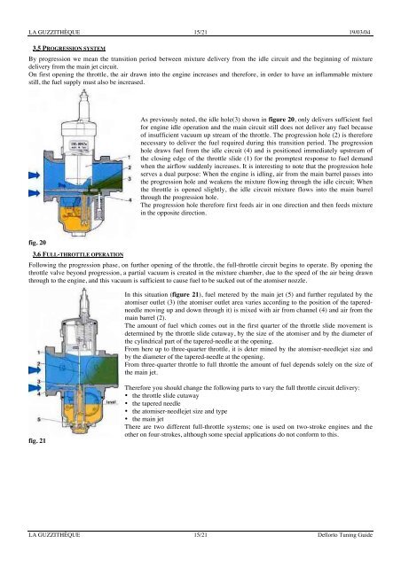
In this situation (figure 21), fuel metered by the main jet (5) and further regulated by the<br />
atomiser outlet (3) (the atomiser outlet area varies according to the position of the taperedneedle<br />
moving up and down through it) is mixed with air from channel (4) and air from the<br />
main barrel (2).<br />
The amount of fuel which comes out in the first quarter of the throttle slide movement is<br />
determined by the throttle slide cutaway, by the size of the atomiser and by the diameter of<br />
the cylindrical part of the tapered-needle at the opening.<br />
From here up to three-quarter throttle, it is deter mined by the atomiser-needlejet size and<br />
by the diameter of the tapered-needle at the opening.<br />
From three-quarter throttle to full throttle the amount of fuel depends solely on the size of<br />
the main jet.<br />
Therefore you should change the following parts to vary the full throttle circuit delivery:<br />
• the throttle slide cutaway<br />
• the tapered needle<br />
• the atomiser-needlejet size and type<br />
• the main jet<br />
There are two different full-throttle systems; one is used on two-stroke engines and the<br />
other on four-strokes, although some special applications do not conform to this.<br />
LA GUZZITHÈQUE 15/21 Dellorto Tuning <strong>Guide</strong>