Rawinsonde and Pibal Observations - Office of the Federal ...
Rawinsonde and Pibal Observations - Office of the Federal ...
Rawinsonde and Pibal Observations - Office of the Federal ...

You also want an ePaper? Increase the reach of your titles
YUMPU automatically turns print PDFs into web optimized ePapers that Google loves.
U.S. DEPARTMENT OF COMMERCE/ National Oceanic <strong>and</strong> Atmospheric Administration<br />
OFFICE OF THE FEDERAL COORDINATOR FOR<br />
METEOROLOGICAL SERVICES AND SUPPORTING RESEARCH<br />
<strong>Federal</strong> Meteorological<br />
H<strong>and</strong>book No. 3<br />
<strong>Rawinsonde</strong><br />
<strong>and</strong><br />
<strong>Pibal</strong><br />
<strong>Observations</strong><br />
FCM-H3-1997<br />
Washington, DC<br />
May 1997
FCM-H3-1997<br />
Washington, DC<br />
May 1997<br />
FEDERAL COORDINATOR<br />
FOR<br />
METEOROLOGICAL SERVICES AND SUPPORTING RESEARCH<br />
8455 Colesville Road, Suite 1500<br />
Silver Spring, Maryl<strong>and</strong> 20910<br />
FEDERAL METEOROLOGICAL HANDBOOK No. 3<br />
RAWINSONDE AND PIBAL OBSERVATIONS
CHANGE AND REVIEW LOG<br />
Use this page to record changes <strong>and</strong> notices <strong>of</strong> reviews.<br />
Change Page Date<br />
Number Numbers Posted Initial<br />
1<br />
Page 6-2 Effective August 1 st 2006 MMC<br />
2<br />
3<br />
4<br />
5<br />
6<br />
7<br />
8<br />
9<br />
10<br />
Changes are indicated by a vertical line in <strong>the</strong> margin next to <strong>the</strong> change or by shading <strong>and</strong> strikeouts.<br />
Review<br />
Date Comments Initial<br />
ii
FOREWORD<br />
In 1987, <strong>the</strong> <strong>Office</strong> <strong>of</strong> <strong>the</strong> <strong>Federal</strong> Coordinator for Meteorology (OFCM) assumed responsibility for<br />
preparing <strong>and</strong> maintaining <strong>Federal</strong> Meteorological H<strong>and</strong>books. The task <strong>of</strong> accomplishing preparation <strong>and</strong><br />
coordination <strong>of</strong> h<strong>and</strong>book No. 3 (FMH-3) — Radiosonde <strong>Observations</strong> <strong>and</strong> associated h<strong>and</strong>books #4, 5, <strong>and</strong><br />
6, was assigned to <strong>the</strong> Ad Hoc Group for FMH-Upper Air (AHG/FMH-UA) through <strong>the</strong> Working Group for<br />
Upper Air <strong>Observations</strong> under <strong>the</strong> Committee for Basic Services (CBS).<br />
This edition <strong>of</strong> FMH-3, "<strong>Rawinsonde</strong> <strong>and</strong> <strong>Pibal</strong> <strong>Observations</strong>," concludes a 5-year effort by <strong>the</strong><br />
AHG/FMH-UA to meet <strong>the</strong> objectives outlined in guidance issued by CBS. Specifically, <strong>the</strong> CBS directed<br />
that <strong>the</strong> new FMH-3 should: (1) reflect our Nation's commitments to international organizations (i.e., WMO,<br />
ICAO); (2) integrate conventional <strong>and</strong> automatically observed data by adopting new st<strong>and</strong>ards for automated,<br />
augmented, <strong>and</strong> manual observations; (3) allow agencies to prepare <strong>and</strong> issue agency-specific procedures <strong>and</strong><br />
instructions for taking <strong>and</strong> reporting upper air observations; <strong>and</strong> (4) combine FMHs 3, 4, 5, <strong>and</strong> 6 into a new<br />
FMH-3. In previous editions <strong>of</strong> <strong>the</strong> <strong>Federal</strong> Meteorological H<strong>and</strong>books, all procedures <strong>and</strong> internal agency<br />
instructions pertaining to upper air observations were described in FMHs 3 through 6. Beginning with this<br />
edition, FMH-3 will contain only <strong>Federal</strong> st<strong>and</strong>ards; it will not contain agency-specific procedures <strong>and</strong><br />
practices.<br />
I would like to acknowledge <strong>the</strong> efforts put forth by members <strong>of</strong> <strong>the</strong> AHG/FMH-UA, past as well as<br />
present, who diligently labored <strong>and</strong> persevered to produce this document. Interagency coordination, especially<br />
<strong>the</strong> establishment <strong>of</strong> new st<strong>and</strong>ards which have impacts on policies <strong>and</strong> procedures, is an extremely difficult<br />
task <strong>and</strong> worthy <strong>of</strong> special recognition. I commend <strong>the</strong> AHG/FMH-UA members for <strong>the</strong>ir efforts.<br />
Julian M. Wright, Jr.<br />
<strong>Federal</strong> Coordinator for Meteorological Services<br />
<strong>and</strong> Supporting Research<br />
iii
FEDERAL METEOROLOGICAL HANDBOOK NO. 3<br />
RAWINSONDE AND PIBAL OBSERVATIONS<br />
TABLE OF CONTENTS<br />
CHANGE AND REVIEW LOG ....................................................... ii<br />
FOREWORD ......................................................................iii<br />
TABLE OF CONTENTS ............................................................. v<br />
LIST OF TABLES ..................................................................xi<br />
LIST OF FIGURES .................................................................xi<br />
CHAPTER 1 INTRODUCTION .................................................... 1- 1<br />
1.1 Purpose <strong>and</strong> Scope .................................................... 1- 1<br />
1.2 Relation to O<strong>the</strong>r H<strong>and</strong>books <strong>and</strong> Manuals ................................. 1- 2<br />
1.3 Changes <strong>and</strong> Revisions ................................................ 1- 2<br />
1.4 Agency Specific Procedures ............................................ 1- 2<br />
1.5 <strong>Rawinsonde</strong> Program - General .......................................... 1- 2<br />
1.6 History <strong>of</strong> U.S. Upper-air Observing Programs.............................. 1- 3<br />
1.7 Present <strong>Rawinsonde</strong> Program ........................................... 1- 3<br />
1.7.1 Network <strong>of</strong> U.S. Stations ............................................... 1- 3<br />
1.7.2 Network Design <strong>and</strong> Configuration ....................................... 1- 4<br />
1.7.3 Transmission <strong>of</strong> <strong>Observations</strong> ........................................... 1- 4<br />
1.7.4 Recording <strong>and</strong> Preserving <strong>Observations</strong> ................................... 1- 4<br />
1.7.5 Data Applications..................................................... 1- 4<br />
CHAPTER 2 SYSTEMS AND EQUIPMENT ..........................................2-1<br />
2.1 Introduction ..........................................................2-1<br />
2.2 Accuracy <strong>and</strong> Precision <strong>of</strong> <strong>the</strong> Measurements ................................2-1<br />
2.3 Flight Subsystem ......................................................2-1<br />
2.3.1 Balloons .............................................................2-1<br />
2.3.2 Flight-Train ..........................................................2-3<br />
2.3.3 Radiosondes ..........................................................2-4<br />
2.4 The Surface Subsystem .................................................2-7<br />
2.4.1 The Antenna..........................................................2-7<br />
2.4.2 The Receiver <strong>and</strong> Sensor Processing Units ..................................2-8<br />
2.5 The Data Processing Subsystem ..........................................2-8<br />
2.5.1 Recording Data .......................................................2-8<br />
2.5.2 Signal Processing ......................................................2-8<br />
2.5.3 Data File Formats......................................................2-9<br />
CHAPTER 3 PREFLIGHT PROCEDURES AND SUCCESS CRITERIA ..................3-1<br />
3.1 Introduction ..........................................................3-1<br />
3.2 Safety Considerations ..................................................3-1<br />
3.3 Flight Equipment Prerelease Actions .......................................3-1<br />
3.3.1 Balloon Inflation <strong>and</strong> Performance ........................................3-1<br />
3.3.2 Balloon Inflation ......................................................3-2<br />
v
3.3.3 Flight-Train Assembly ..................................................3-2<br />
3.4 Preparing <strong>the</strong> Radiosonde for <strong>the</strong> Preflight Check .............................3-2<br />
3.4.1 Calibration <strong>of</strong> <strong>the</strong> Radiosonde Sensors .....................................3-2<br />
3.4.2 The Surface Observation ................................................3-3<br />
3.4.3 NAVAID Radiosonde ..................................................3-3<br />
3.4.4 Release Notifications ...................................................3-3<br />
3.5 Notice to Airmen (NOTAM) .............................................3-4<br />
3.6 The Release ..........................................................3-4<br />
3.6.1 Release into Thunderstorms ..............................................3-5<br />
3.6.2 Delayed Release .......................................................3-5<br />
3.7 Termination <strong>of</strong> Radiosonde Observation ....................................3-5<br />
3.7.1 Due to Missing Data ...................................................3-5<br />
3.7.2 Due to Weak Signal ....................................................3-5<br />
3.7.3 O<strong>the</strong>r Reasons for Termination ...........................................3-5<br />
3.8 Successful/Unsuccessful Observation Criteria ...............................3-5<br />
3.9 Multiple Releases ......................................................3-6<br />
3.10 Unscheduled or Special <strong>Observations</strong> ......................................3-6<br />
CHAPTER 4 QUALITY CONTROL AT THE STATIONS ..............................4-1<br />
4.1 Introduction ..........................................................4-1<br />
4.2 Pressure Anomalies ....................................................4-1<br />
4.2.1 Anomalies Caused By Pressure Sensor or Radiosonde Failure ...................4-1<br />
4.2.2 Anomalies Caused By Balloon ...........................................4-2<br />
4.2.3 Anomalies Caused by Atmospheric Events ..................................4-3<br />
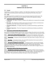
4.3 Temperature Anomalies.................................................4-3<br />
4.3.1 Anomalies Caused By Temperature Sensor or Radiosonde Failure ...............4-3<br />
4.3.2 Superadiabatic Lapse Rates ..............................................4-4<br />
4.4 Relative Humidity Anomalies ............................................4-5<br />
4.4.1 Missing Relative Humidity Data..........................................4-5<br />
4.4.2 Erroneous RH Data ....................................................4-5<br />
4.4.3 RH Data Biased Too High or Too Low .....................................4-6<br />
4.4.4 Rapid Change in RH Immediately After Release .............................4-6<br />
4.5 Wind Anomalies ......................................................4-7<br />
4.5.1 Anomalous Wind Data From Radio Direction Finding (RDF) Systems ............4-6<br />
4.5.2 Anomalous Wind Data From NAVAID (LORAN or GPS) Systems ..............4-8<br />
4.5.3 Doubtful Wind Data ....................................................4-9<br />
CHAPTER 5 PROCESSING SOUNDING DATA .......................................5-1<br />
5.1 Introduction ..........................................................5-1<br />
5.2 Level Selection - Thermodynamic Variables.................................5-1<br />
5.2.1 St<strong>and</strong>ard Pressure Levels ................................................5-2<br />
5.2.2 M<strong>and</strong>atory Significant Levels ............................................5-2<br />
5.2.3 Additional Level Selection ..............................................5-5<br />
5.3 Wind Data ...........................................................5-5<br />
5.3.1 Fixed Levels for Reporting Purposes.......................................5-6<br />
5.3.2 Additional Winds......................................................5-6<br />
5.3.3 Terminating Wind .....................................................5-7<br />
5.3.4 Maximum Winds ......................................................5-7<br />
vi
5.3.5 Primary <strong>and</strong> Secondary Maximum Winds ...................................5-7<br />
5.3.6 Wind Shear ..........................................................5-8<br />
5.3.7 Mean Winds..........................................................5-8<br />
5.3.8 O<strong>the</strong>r Factors .........................................................5-8<br />
5.4 Selecting <strong>the</strong> Tropopause ................................................5-9<br />
5.4.1 The First Tropopause ...................................................5-9<br />
5.4.2 Multiple Tropopause Levels ............................................5-10<br />
5.4.3 Reporting ...........................................................5-10<br />
5.5 Coded Message Generation .............................................5-10<br />
5.6 Additional Information ................................................5-10<br />
CHAPTER 6 PILOT BALLOON OBSERVATIONS ...................................6-1<br />
6.1 Introduction ..........................................................6-1<br />
6.2 The <strong>Pibal</strong> Observation ..................................................6-1<br />
6.3 Selecting <strong>the</strong> Site ......................................................6-1<br />
6.4 The Theodolite ........................................................6-3<br />
6.4.1 Optical features .......................................................6-3<br />
6.4.2 Angular Measurements .................................................6-3<br />
6.4.3 O<strong>the</strong>r Features ........................................................6-3<br />
6.5 Theodolite Leveling <strong>and</strong> Orientation .......................................6-6<br />
6.6 Focusing <strong>the</strong> Theodolite .................................................6-6<br />
6.7 General Test..........................................................6-6<br />
6.8 The Observation.......................................................6-6<br />
6.8.1 Release Time .........................................................6-7<br />
6.8.2 Theodolite Preparation ..................................................6-7<br />
6.9 Balloons .............................................................6-7<br />
6.10 Night <strong>Pibal</strong> Lighting Units...............................................6-7<br />
6.11 Train Assembly .......................................................6-8<br />
6.12 The Release ..........................................................6-8<br />
6.13 Errors Encountered in Tracking <strong>the</strong> Balloon .................................6-8<br />
6.13.1 Extraneous Light ......................................................6-8<br />
6.13.2 Sun in Field ..........................................................6-8<br />
6.13.3 Confusion <strong>of</strong> Stars with <strong>the</strong> Lighting Device.................................6-8<br />
6.14 Termination ..........................................................6-9<br />
6.15 Preliminary Inspection <strong>of</strong> Data ...........................................6-9<br />
6.16 Criteria for Satisfactory <strong>Observations</strong> ......................................6-9<br />
6.17 <strong>Pibal</strong> Evaluation......................................................6-10<br />
6.17.1 Missing Data ........................................................6-10<br />
6.17.2 Errors ..............................................................6-10<br />
6.18 The <strong>Pibal</strong> Message ....................................................6-11<br />
6.19 Theodolite Care <strong>and</strong> Adjustments ........................................6-11<br />
6.20 Storage Between <strong>Observations</strong> ..........................................6-11<br />
CHAPTER 7 DATA DISSEMINATION ..............................................7-1<br />
7.1 Introduction ..........................................................7-1<br />
7.2 Global, Regional, <strong>and</strong> National Telecommunications ..........................7-1<br />
7.2.1 The Regional Telecommunications System..................................7-1<br />
7.2.2 National Telecommunications Systems .....................................7-1<br />
vii
7.3 WMO Index Numbers ..................................................7-1<br />
7.3.1 Assignment <strong>of</strong> International Station Index Numbers...........................7-2<br />
7.3.2 Obtaining Assignments <strong>of</strong> WMO Block/Station Numbers ......................7-2<br />
7.4 Transmitting <strong>Rawinsonde</strong> Reports .........................................7-3<br />
7.4.1 RADAT ............................................................7-3<br />
7.5 Data Archiving........................................................7-3<br />
CHAPTER 8 QUALITY ASSURANCE ..............................................8-1<br />
8.1 Introduction ..........................................................8-1<br />
8.2 Monitoring <strong>and</strong> Quality Control ..........................................8-1<br />
8.2.1 Operational Quality Control .............................................8-1<br />
8.2.2 Administrative Quality Control ...........................................8-2<br />
8.2.3 WMO Reports ........................................................8-2<br />
8.3 Coordination <strong>and</strong> Quality Assurance .......................................8-3<br />
8.3.1 The National <strong>and</strong> Regional Headquarters ...................................8-4<br />
8.3.2 Exchange <strong>of</strong> Information Notifying Individual Upper-air Units ..................8-4<br />
8.4 Documenting Quality Information for Archival Data ..........................8-4<br />
APPENDIX A. REFERENCES .................................................... A-1<br />
APPENDIX B. OBSERVATION SITE SPECIFICATIONS ............................ B-1<br />
B.1 Introduction ....................................................... B-1<br />
B.2 Site St<strong>and</strong>ards ...................................................... B-1<br />
B.2.1 Surveying <strong>the</strong> Site................................................... B-2<br />
B.2.2 Posting <strong>the</strong> Location <strong>of</strong> Wires Antennas, <strong>and</strong> O<strong>the</strong>r Obstructions .............. B-2<br />
B.2.3 Developing <strong>the</strong> RDF Limiting Angles Table .............................. B-2<br />
B.2.4 Developing <strong>the</strong> Surface Elevation/Launch Elevation Pressure Correction Table . . B-2<br />
B.3 Equipment Orientation Checks......................................... B-2<br />
B.4 Equipment <strong>and</strong> Shelter Considerations................................... B-3<br />
B.5 Inflation Gasses .................................................... B-4<br />
B.5.1 Hydrogen Cylinders ................................................. B-4<br />
B.5.2 Pressure Regulation ................................................. B-4<br />
B.5.3 Heat/Leak Detectors ................................................. B-4<br />
B.5.4 Inflation Equipment - Hydrogen Cylinders ............................... B-4<br />
B.5.5 Inflation Equipment - Hydrogen Generators .............................. B-5<br />
B.6 Safety St<strong>and</strong>ards for Hydrogen Gas ..................................... B-5<br />
B.6.1 Grounding ......................................................... B-5<br />
B.6.2 The Hydrogen Safety Switch .......................................... B-5<br />
B.6.3 Electrical Components ............................................... B-5<br />
B.6.4 Hydrogen Housing .................................................. B-6<br />
B.6.5 Storage <strong>of</strong> Flammable Materials........................................ B-6<br />
B.6.6 Fire Extinguishers ................................................... B-6<br />
B.6.7 Additional Equipment................................................ B-6<br />
B.7 Procedure for Ground Equipment ....................................... B-7<br />
B.8 Hydrogen Generator Maintenance ...................................... B-7<br />
B.9 General Safety ..................................................... B-7<br />
B.9.1 Smoking .......................................................... B-7<br />
viii
B.9.2 Safety Instructions .................................................. B-7<br />
B.9.3 Inflation Building Safety Inspections .................................... B-7<br />
B.9.4 Daily Inspections ................................................... B-7<br />
B.9.5 Annual Inspections <strong>of</strong> Inflation Facilities ................................. B-8<br />
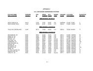
APPENDIX C. U.S. LAND-BASED RAWINSONDE STATIONS ....................... C-1<br />
APPENDIX D. COMPUTATIONAL FORMULAE AND CONSTANTS .................. D-1<br />
D.1 Radiosonde Sensors <strong>and</strong> Data Reduction ................................. D-1<br />
D.2 Geopotential Height ................................................. D-1<br />
D.3 Thermodynamic Relationships ......................................... D-3<br />
D.3.1 Vapor Pressure ..................................................... D-3<br />
D.3.2 Virtual Temperature ................................................. D-3<br />
D.3.3 Dew Point <strong>and</strong> Dew Point Depression ................................... D-3<br />
D.4 Mixing Ratio....................................................... D-4<br />
D.5 Potential Temperature................................................ D-4<br />
D.6 Wind Variables ..................................................... D-4<br />
D.6.1 Wind Speed <strong>and</strong> Direction ............................................ D-4<br />
D.6.2 Wind Shear ........................................................ D-5<br />
D.7 Location <strong>of</strong> <strong>the</strong> Balloon .............................................. D-5<br />
D.8 Three-Dimensional Balloon Location ................................... D-5<br />
D.9 Logarithmic Pressure Ratio (for Interpolation to Selected Pressure) ............ D-6<br />
APPENDIX E. PILOT BALLOON AND RAWINSONDE<br />
ENCODING AND DECODING ...................................... E-1<br />
Table <strong>of</strong> Contents ........................................................... E-2<br />
E.1 Introduction ............................................................ E-3<br />
E.2WMO Code Forms ....................................................... E-3<br />
E.3 Symbolic Forms for Data Groups ............................................ E-4<br />
E.4 References to Level Coding ................................................ E-4<br />
E.5Basic Code Construction .................................................. E-4<br />
E.5.1 Versions <strong>of</strong> <strong>the</strong> PILOT Message ......................................... E-4<br />
E.5.2 Versions <strong>of</strong> <strong>the</strong> TEMP Message .......................................... E-6<br />
E.6Numbering System <strong>of</strong> International Code Tables ............................... E-7<br />
Appendix E-I Code Form for PILOT <strong>Observations</strong> ............................... E-9<br />
E-I.1 CODE FORM: PILOT Parts A,B,C, <strong>and</strong> D by Section Number ................ E-9<br />
E-I.2 CODE FORM: PILOT Upper Wind Report Code Forms ..................... E-12<br />
E-I.2.1 Section 1 - Identification <strong>and</strong> Position Data ............................... E-12<br />
E-I.2.2 Section 2 - Data for St<strong>and</strong>ard Isobaric Surfaces ............................ E-15<br />
E-I.2.3 Section 3 - Data for Max Wind Levels ................................... E-16<br />
E-I.2.4 Section 4 - Data for Fixed Additional Levels .............................. E-19<br />
E-I.2.5 Section 5 - Regional Code Groups ....................................... E-23<br />
E-I.2.6 Section 6 - National Code Groups ....................................... E-23<br />
Appendix E-II Code Form for TEMP <strong>Rawinsonde</strong> <strong>Observations</strong> .................... E-24<br />
E-II.1 CODE FORM: TEMP Parts up to <strong>and</strong> including <strong>the</strong> 100 hPa Surface<br />
<strong>and</strong> Parts C <strong>and</strong> D Above <strong>the</strong> 100 hPa Surface .......................... E-24<br />
ix
E-II.2 CODE FORM: TEMP Upper-level Pressure, Temperature, Humidity<br />
<strong>and</strong> Wind Report Code Forms ............................................. E-27<br />
E-II.2.1 Section 1 - Identification <strong>and</strong> Position Data ............................ E-27<br />
E-II.2.2 Section 2 - Data for St<strong>and</strong>ard Isobaric Surfaces ......................... E-30<br />
E-II.2.3 Section 3 - Data for Tropopause Level(s) .............................. E-32<br />
E-II.2.4 Section 4 - Data for Max Wind Levels ................................ E-33<br />
E-II.2.5 Section 5 - Data for Additional Levels (Temperature) .................... E-35<br />
E-II.2.6 Section 6 - Data for Additional Levels (Winds) ......................... E-39<br />
E-II.2.7 Section 7 - Data on Sea Surface Temperature <strong>and</strong> Sounding System ......... E-40<br />
E-II.2.8 Section 8 - Cloud Data ............................................ E-41<br />
E-II.2.9 Section 9 - Code Groups Developed Regionally ......................... E-43<br />
E-II.2.10 Section 10 - Code GroupsDeveloped Nationally ........................ E-43<br />
Appendix E-III Required Code Tables for PILOT <strong>and</strong> TEMP Code Forms ............. E-44<br />
Table <strong>of</strong> Contents to Appendix E-III ........................................... E-44<br />
APPENDIX F. ARCHIVING .......................................................F-1<br />
F.1 Introduction ........................................................F-1<br />
F.2 Data Centers ........................................................F-1<br />
F.3 Data Transfer to <strong>the</strong> Data Centers........................................F-1<br />
F.4 Station Information..................................................F-15<br />
APPENDIX G. GLOSSARY ...................................................... G-1<br />
x
LIST OF TABLES<br />
2-1. Accuracy <strong>and</strong> Precision <strong>of</strong> <strong>the</strong> Variables ..........................................2-2<br />
2-2. Radiosonde Telemetry Frequencies ..............................................2-7<br />
3-1 Termination Due to Missing Temperature Data: Maximum Tolerable Amounts ...........3-6<br />
5-1 Stability Index Station Base Levels ..............................................5-4<br />
5-2 Altitudes <strong>of</strong> <strong>the</strong> Fixed Wind Levels ..............................................5-6<br />
6-1 Ascension Rate Table .........................................................6-2<br />
7-1 Deadlines (in minutes after release time R) for Transmission <strong>of</strong> Scheduled Synoptic<br />
<strong>Rawinsonde</strong> <strong>Observations</strong> ......................................................7-3<br />
8-1 Specific Components Involved in Upper Air <strong>Observations</strong> ............................8-3<br />
LIST OF FIGURES<br />
2-1 Schematic <strong>of</strong> a sonde with balloon, parachute, <strong>and</strong> train ..............................2-3<br />
4-1 Plot <strong>of</strong> temperature vs. Time showing incidents <strong>of</strong> missing <strong>and</strong> spurious data values ........4-4<br />
6-1a Theodolite <strong>of</strong> <strong>the</strong> type used at l<strong>and</strong> stations ........................................6-4<br />
6-1b Theodolite <strong>of</strong> <strong>the</strong> type used at l<strong>and</strong> stations ........................................6-5<br />
B-1 Sample compass declination chart .............................................. B-3<br />
E-1 Assignment <strong>of</strong> Marsden Square numbers ........................................ E-59<br />
E-2 Assignment <strong>of</strong> Marsden Square numbers for polar zones............................ E-60<br />
E-3 Subdivisions <strong>of</strong> <strong>the</strong> Marsden 10-degree squares into one-degree squares<br />
for <strong>the</strong> eight octants (Q) <strong>of</strong> <strong>the</strong> globe ........................................... E-61<br />
xi
xii
CHAPTER 1<br />
INTRODUCTION<br />
1.1 Purpose <strong>and</strong> Scope. A radiosonde is a balloon-borne instrument used to simultaneously measure <strong>and</strong><br />
transmit meteorological data while ascending through <strong>the</strong> atmosphere. The instrument consists <strong>of</strong> sensors for<br />
<strong>the</strong> measurement <strong>of</strong> pressure, temperature, <strong>and</strong> relative humidity. The sensors' information is transmitted in<br />
a predetermined sequence to <strong>the</strong> ground receiving station where that information is processed at some fixed<br />
time interval. When wind information is processed by tracking <strong>the</strong> balloon's movement <strong>the</strong> instrument<br />
package is termed a rawinsonde. Thus, rawinsonde observations <strong>of</strong> <strong>the</strong> atmosphere describe <strong>the</strong> vertical<br />
pr<strong>of</strong>ile <strong>of</strong> temperature, humidity, <strong>and</strong> wind direction <strong>and</strong> speed as a function <strong>of</strong> pressure <strong>and</strong> height from <strong>the</strong><br />
surface to <strong>the</strong> altitude where <strong>the</strong> sounding is terminated. O<strong>the</strong>r derived parameters are also determined from<br />
a rawinsonde observation. The rawinsonde system consists <strong>of</strong> a balloon-borne radiosonde, receiving <strong>and</strong><br />
tracking equipment, <strong>and</strong> computer systems for data processing. <strong>Pibal</strong> (pilot balloon) observations are<br />
soundings to delineate <strong>the</strong> vertical pr<strong>of</strong>ile <strong>of</strong> wind direction <strong>and</strong> speed as a function <strong>of</strong> height. They are made<br />
by <strong>the</strong> tracking <strong>of</strong> a balloon by optical means or by radar equipment. In this H<strong>and</strong>book only <strong>the</strong> opticallytracked<br />
balloon will be considered.<br />
This H<strong>and</strong>book prescribes federal st<strong>and</strong>ards for taking rawinsonde <strong>and</strong> pibal observations; for<br />
processing <strong>the</strong> observations; <strong>and</strong> for encoding, telecommunicating, <strong>and</strong> archiving <strong>the</strong> data. Also provided are<br />
procedures for quality control throughout <strong>the</strong> various phases <strong>of</strong> data acquisition, processing, <strong>and</strong><br />
dissemination. All methodology contained in this H<strong>and</strong>book is consistent with that stipulated by <strong>the</strong> World<br />
Meteorological Organization (WMO).<br />
The st<strong>and</strong>ards defined in this H<strong>and</strong>book apply to all U.S. government agencies or o<strong>the</strong>r U.S. facilities<br />
which take routine synoptic or unscheduled rawinsonde <strong>and</strong> pibal observations. The dissemination st<strong>and</strong>ards<br />
<strong>and</strong> requirements herein apply to all rawinsonde <strong>and</strong> pibal data transmitted over broadcast communication<br />
systems <strong>and</strong>/or use by <strong>the</strong> public or <strong>the</strong> government. Examples <strong>of</strong> such broadcast systems are satellites, <strong>the</strong><br />
Automation <strong>of</strong> Field Operations <strong>and</strong> Services (AFOS) system, <strong>the</strong> Automated Wea<strong>the</strong>r Network (AWN)<br />
system, <strong>and</strong> <strong>the</strong> Global Telecommunications System (GTS). The st<strong>and</strong>ards <strong>and</strong> requirements also apply to<br />
all U.S. Agencies which provide rawinsonde <strong>and</strong> pibal data for archival at <strong>the</strong> World Data Center-A for<br />
Meteorology located at <strong>the</strong> National Climatic Data Center (NCDC), Asheville, North Carolina. Fur<strong>the</strong>r, this<br />
H<strong>and</strong>book is a reference <strong>and</strong> guide to <strong>the</strong> various users <strong>of</strong> upper-air data <strong>and</strong> to private enterprises engaged<br />
in <strong>the</strong> development <strong>of</strong> observational systems.<br />
Throughout this manual, <strong>the</strong> following definitions apply:<br />
! "shall" indicates that a procedure or practice is m<strong>and</strong>atory.<br />
! "should" indicates that a procedure or practice is recommended.<br />
! "may" indicates that a procedure or practice is optional.<br />
! "will" indicates futurity, not a requirement to be applied to current practices.<br />
1-1
1.2 Relation to O<strong>the</strong>r H<strong>and</strong>books <strong>and</strong> Manuals. This version <strong>of</strong> FMH No. 3, <strong>Rawinsonde</strong> <strong>and</strong> <strong>Pibal</strong><br />
<strong>Observations</strong>, supersedes <strong>and</strong> replaces <strong>the</strong> predecessor <strong>Federal</strong> Meteorological H<strong>and</strong>books:<br />
! FMH No. 3 ! FMH No.4<br />
- Radiosonde <strong>Observations</strong> - Radiosonde Code<br />
! FMH No. 5 ! FMH No. 6<br />
- Winds Al<strong>of</strong>t <strong>Observations</strong> - Winds Al<strong>of</strong>t Code<br />
1.3 Changes <strong>and</strong> Revisions. Changes <strong>and</strong> revisions to this H<strong>and</strong>book will be made under <strong>the</strong> direction <strong>of</strong><br />
<strong>the</strong> <strong>Office</strong> <strong>of</strong> <strong>the</strong> <strong>Federal</strong> Coordinator for Meteorological Services <strong>and</strong> Supporting Research (OFCM).<br />
Agencies shall submit recommendations for changes through <strong>the</strong>ir representatives to <strong>the</strong> OFCM.<br />
1.4 Agency Specific Procedures. Agencies may issue supplemental instructions, but such instructions are<br />
not to be identified as part <strong>of</strong> this H<strong>and</strong>book. If agencies intend to enter data collected under <strong>the</strong> supplemental<br />
instructions into <strong>the</strong> GTS, <strong>the</strong> data shall meet or exceed <strong>the</strong> basic provisions <strong>of</strong> this H<strong>and</strong>book.<br />
1.5 <strong>Rawinsonde</strong> Program - General. The United States <strong>and</strong> o<strong>the</strong>r WMO member countries maintain, on<br />
a cooperative basis, observing locations that cumulatively form part <strong>of</strong> The Global Observing System <strong>of</strong> <strong>the</strong><br />
World Wea<strong>the</strong>r Watch (WWW) network. The synoptic rawinsonde observing programs <strong>of</strong> <strong>the</strong> United States<br />
<strong>and</strong> <strong>the</strong> o<strong>the</strong>r WMO member countries are designed to meet real-time operational needs for wea<strong>the</strong>r analysis<br />
<strong>and</strong> forecasting. These observations also provide a national <strong>and</strong> international data base <strong>of</strong> upper-air<br />
observations for research <strong>and</strong> climatological purposes. Synoptic observations are defined as those that are<br />
being taken simultaneously at fixed, scheduled times at a large number <strong>of</strong> locations. Unscheduled<br />
observations are those taken in support <strong>of</strong> specific missions without regard to long-term continuing, fixed<br />
scheduled times.<br />
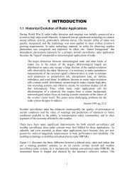
1.6 History <strong>of</strong> U.S. Upper-air Observing Programs. Upper-air observations began in <strong>the</strong> United States<br />
as early as 1749 with experiments using large kites to carry al<strong>of</strong>t primitive instruments. Later in <strong>the</strong> eighteenth<br />
century, experiments were conducted using te<strong>the</strong>red balloons so that observations could be made on calm as<br />
well as windy days. The advent <strong>of</strong> <strong>the</strong> airplane provided a means to carry al<strong>of</strong>t <strong>and</strong> safely return recording<br />
instruments that were impractical for use with balloons. In 1920, <strong>the</strong> U.S. Wea<strong>the</strong>r Bureau <strong>and</strong> <strong>the</strong> Army Air<br />
Corps established a program <strong>of</strong> daily airplane upper-air observations at about 20 locations nationwide. These<br />
provided <strong>the</strong> first national coverage <strong>of</strong> upper-air data.<br />
In 1921, <strong>the</strong> U.S. Wea<strong>the</strong>r Bureau established a kite network which remained in operation until 1933.<br />
In <strong>the</strong> meantime, free-flight pilot balloons, tracked visually with a <strong>the</strong>odolite, were being used to determine<br />
winds al<strong>of</strong>t.<br />
Around 1930, radio telemetry was successfully incorporated with balloon-borne atmospheric sensing<br />
instrumentation, <strong>the</strong> forerunner <strong>of</strong> today's rawinsonde/radiosonde program. A radiosonde network in <strong>the</strong><br />
coterminous U.S. was begun by <strong>the</strong> (<strong>the</strong>n) Wea<strong>the</strong>r Bureau in 1937-38. World War II provided special<br />
impetus in development <strong>of</strong> <strong>the</strong> rawinsonde/radiosonde technology <strong>and</strong> fostered <strong>the</strong> growth <strong>of</strong> upper-air<br />
observing networks.<br />
1-2
Before computerized processing <strong>of</strong> upper-air observation data became <strong>the</strong> norm, <strong>the</strong> process involved<br />
a significant amount <strong>of</strong> manual labor. The observation process was generally considered a two-person effort,<br />
with a third person frequently involved for quality control, general oversight <strong>of</strong> procedures, <strong>and</strong> assistance.<br />
All aspects <strong>of</strong> <strong>the</strong> observation, from preparation for <strong>the</strong> sounding release through subjective recorder recordtrace<br />
evaluation to preparation <strong>of</strong> adiabatic charts <strong>and</strong> <strong>the</strong> coded message, were manually performed <strong>and</strong> labor<br />
intensive. The process <strong>of</strong> preparation, evaluation, <strong>and</strong> coded message generation typically took an additional<br />
period <strong>of</strong> time equal to or greater than <strong>the</strong> period <strong>of</strong> time required for <strong>the</strong> actual observation. U.S. agencies<br />
began experimenting with computerized reduction <strong>of</strong> rawinsonde data during <strong>the</strong> late 1960s <strong>and</strong> early 1970s.<br />
In <strong>the</strong> 1980's, technological advances in telemetry <strong>and</strong> small computers made near-fully automated<br />
rawinsonde observations feasible. At U.S. locations, manual involvement in taking rawinsonde observations<br />
was significantly reduced. By <strong>the</strong> middle 1980s both <strong>the</strong> National Oceanic <strong>and</strong> Atmospheric Administration<br />
(NOAA) <strong>and</strong> <strong>the</strong> Department <strong>of</strong> Defense (DoD) had made significant progress in automation. The use <strong>of</strong><br />
station minicomputers <strong>and</strong> interfaces to automatically acquire flight data meant that <strong>the</strong> data computations,<br />
coded message generation, data transfer, <strong>and</strong> data storage functions could all be performed with minimal<br />
human intervention. The rawinsonde observation had thus become an operation with improved data quality,<br />
even though <strong>the</strong> time required for preparing radiosonde data for transmission had been reduced to, typically,<br />
less than one staff hour.<br />
Currently, <strong>the</strong> upper-air observing program <strong>of</strong> <strong>the</strong> U.S. comprises a network <strong>of</strong> rawinsonde stations<br />
toge<strong>the</strong>r with a number <strong>of</strong> additional observing systems, including pibals, a network <strong>of</strong> ground-based remotesensing<br />
wind pr<strong>of</strong>ilers, en route commercial aircraft, <strong>and</strong> satellite-based temperature pr<strong>of</strong>ile <strong>and</strong> cloud-motion<br />
wind capability. Toge<strong>the</strong>r <strong>the</strong>se systems provide upper-air measurements that are basic to meeting <strong>the</strong> needs<br />
<strong>of</strong> operational wea<strong>the</strong>r forecasting, climatological data bases, <strong>and</strong> meteorological research programs.<br />
1.7 Present <strong>Rawinsonde</strong> Program. The U.S. participates in <strong>the</strong> WMO's World Wea<strong>the</strong>r Watch program<br />
by maintaining <strong>and</strong> operating <strong>the</strong> Washington D.C. World Meteorological Center (WMC); <strong>the</strong> WMO Region<br />
IV Regional Telecommunication Hub (RTH), which is responsible for North <strong>and</strong> Central America <strong>and</strong><br />
adjacent ocean areas; <strong>and</strong> radiosonde facilities at a network <strong>of</strong> civilian <strong>and</strong> military sites on its major l<strong>and</strong><br />
masses <strong>and</strong> remote isl<strong>and</strong> locations. The Washington D.C. WMC comprises <strong>the</strong> NOAA National Wea<strong>the</strong>r<br />
Service Telecommunication Gateway (NWSTG) <strong>and</strong> <strong>the</strong> National Centers for Environmental Prediction<br />
(NCEP). Toge<strong>the</strong>r <strong>the</strong>y fulfill global <strong>and</strong> regional telecommunications, data processing, <strong>and</strong> data monitoring<br />
responsibilities for <strong>the</strong> WMO.<br />
The U.S. program for rawinsonde <strong>and</strong> pibal observations assists in meeting <strong>the</strong> data requirements <strong>of</strong><br />
<strong>the</strong> international, regional, national, state, <strong>and</strong> local forecast centers <strong>and</strong> <strong>of</strong>fices. The basic requirements<br />
include station spacing <strong>and</strong> density, frequency <strong>of</strong> observations, precision <strong>and</strong> accuracy <strong>of</strong> data, <strong>and</strong> resolution<br />
<strong>of</strong> measurements. The requirements may be supplemented to meet special mission needs but shall not be<br />
diminished, except in emergencies, to less than <strong>the</strong> st<strong>and</strong>ards for routine scheduled operations. A list <strong>of</strong> <strong>the</strong><br />
upper-air sites operated by <strong>the</strong> U.S. is given in Appendix C.<br />
<strong>Pibal</strong> observations are taken mainly by Department <strong>of</strong> Defense operations in <strong>the</strong> field, <strong>and</strong> are used<br />
primarily for artillery support.<br />
1-3
1.7.1 Network <strong>of</strong> U.S. Stations. The U.S. network <strong>of</strong> stations comprises more than ten percent <strong>of</strong><br />
<strong>the</strong> global rawinsonde network. The primary responsibility for maintaining this network rests with NOAA’s<br />
National Wea<strong>the</strong>r Service (NWS). The network is augmented by observations made at military, National<br />
Aeronautics <strong>and</strong> Space Administration (NASA), Department <strong>of</strong> Energy (DoE), <strong>and</strong> o<strong>the</strong>r installations.<br />
Regardless <strong>of</strong> <strong>the</strong> purpose for <strong>the</strong> observations, agencies that do acquire rawinsonde <strong>and</strong> pibal observations<br />
<strong>and</strong> communicate <strong>the</strong>m for general use shall comply with <strong>the</strong> provisions <strong>of</strong> this H<strong>and</strong>book.<br />
1.7.2 Network Design <strong>and</strong> Configuration. The proper frequency <strong>and</strong> spacing <strong>of</strong> rawinsonde <strong>and</strong><br />
pibal observations, toge<strong>the</strong>r with o<strong>the</strong>r types <strong>of</strong> upper-air measurements (i. e. satellite, aircraft <strong>and</strong> groundbased<br />
remote-sensing systems), enable identification <strong>and</strong> prediction <strong>of</strong> meteorological phenomena to protect<br />
human life <strong>and</strong> promote economic interests.<br />
Many factors influence <strong>the</strong> size <strong>of</strong> <strong>the</strong> U.S. network <strong>and</strong> <strong>the</strong> locations <strong>of</strong> stations. Operational<br />
requirements play a central role in determining <strong>the</strong> network <strong>of</strong> stations <strong>and</strong> types <strong>of</strong> observing systems needed<br />
to describe <strong>the</strong> state <strong>of</strong> <strong>the</strong> atmosphere. Budgetary realities, in terms <strong>of</strong> existing <strong>and</strong> planned appropriations,<br />
determine agencies' ability to establish <strong>and</strong> sustain operations over an extended period <strong>of</strong> time. Logistics<br />
determine <strong>the</strong> ability to supply <strong>and</strong> maintain each station on a continuing basis. Geography determines an<br />
optimum location for each station, taking into account terrain, climatology, urban development, <strong>and</strong> o<strong>the</strong>r<br />
physical considerations. O<strong>the</strong>r important factors include national security requirements, special research<br />
studies (particularly <strong>of</strong> severe storms <strong>and</strong> in support <strong>of</strong> international programs), <strong>and</strong> needs for observations<br />
in support <strong>of</strong> special events.<br />
The WMO recommends a minimum upper-air station spacing <strong>of</strong> about 250 km over large l<strong>and</strong> areas<br />
<strong>and</strong> 1000 km over sparsely populated <strong>and</strong> oceanic regions <strong>and</strong> fur<strong>the</strong>r recommends that observations be taken<br />
one-to-four times daily (Ref 12: II.2, II.3). The average continental U.S. rawinsonde station separation is<br />
presently about 315 km, <strong>and</strong> two observations daily (at 0000 <strong>and</strong> 1200 UTC) are scheduled.<br />
1.7.3 Transmission <strong>of</strong> <strong>Observations</strong>. The coded report containing data from <strong>the</strong> observation, when<br />
presented to <strong>the</strong> telecommunication system for dissemination to <strong>the</strong> general public <strong>and</strong> government agencies,<br />
shall adhere to <strong>the</strong> st<strong>and</strong>ards set forth in Chapter 7 <strong>and</strong> Appendix E. Telecommunication systems are<br />
described in Chapter 7 <strong>and</strong> detailed description <strong>of</strong> <strong>the</strong> coding procedure is contained in Appendix E.<br />
1.7.4 Recording <strong>and</strong> Preserving <strong>Observations</strong>. An archive record <strong>of</strong> all regular synoptic<br />
rawinsonde <strong>and</strong> pibal observations shall be made for presentation to NCDC. An archive record shall also be<br />
made <strong>of</strong> unscheduled observations that are transmitted over telecommunications for use by <strong>the</strong> public or <strong>the</strong><br />
government. The requirements for recording <strong>and</strong> transmitting <strong>the</strong>se records to <strong>the</strong> NCDC are described in<br />
Appendix F.<br />
1.7.5 Data Applications. <strong>Rawinsonde</strong> observation data are applied to a broad spectrum <strong>of</strong><br />
operational, climatological, <strong>and</strong> research efforts. Applications include: initialization for numerical wea<strong>the</strong>r<br />
prediction models; input for pollution/dispersion models; severe storm, general, aviation, <strong>and</strong> marine<br />
forecasts; climatology records <strong>and</strong> atlases; ground truth for satellite retrieval algorithm development <strong>and</strong><br />
verification; support for DoD programs; climate studies; <strong>and</strong> general research.<br />
1-4
CHAPTER 2<br />
SYSTEMS AND EQUIPMENT<br />
2.1 Introduction. This chapter describes <strong>the</strong> upper-air sounding systems <strong>and</strong> associated equipment used for<br />
fixed l<strong>and</strong>-based, shipboard, <strong>and</strong> mobile rawinsonde observations taken by U.S. agencies. Upper-air systems<br />
are composed <strong>of</strong> a flight subsystem (inflated balloon, flight-train, radiosonde) <strong>and</strong> a ground-based subsystem<br />
(tracking, receiving, <strong>and</strong> signal- <strong>and</strong> data-processing equipment).<br />
2.2 Accuracy <strong>and</strong> Precision <strong>of</strong> <strong>the</strong> Measurements. Table 2-1 presents accuracies <strong>and</strong> functional precisions<br />
<strong>of</strong> <strong>the</strong> measured variables: <strong>the</strong>se shall be considered minimum st<strong>and</strong>ards. They are not to be interpreted as<br />
technical st<strong>and</strong>ards, but as quantities easily achievable with present (1997) technologies. Two important<br />
points about <strong>the</strong>se specifications should be noted. The accuracy <strong>and</strong> precision <strong>of</strong> wind measurements depends<br />
upon <strong>the</strong> balloon-tracking system employed <strong>and</strong> <strong>the</strong> conditions under which <strong>the</strong> sounding is made. The<br />
geopotential height values are calculated <strong>and</strong> are a complicated function <strong>of</strong> <strong>the</strong> accuracy <strong>and</strong> precision <strong>of</strong> <strong>the</strong><br />
individual pressure, temperature, <strong>and</strong> humidity variables. The values in <strong>the</strong> Table are based upon actual field<br />
tests (see Table 2-1 footnote #3).<br />
2.3 Flight Subsystem. The flight subsystem is composed <strong>of</strong> a balloon, flight-train, <strong>and</strong> radiosonde. The<br />
free-flight meteorological sounding balloon is designed to lift <strong>the</strong> radiosonde to a desired height at a desired<br />
ascension rate. The flight-train connects <strong>the</strong> radiosonde to <strong>the</strong> balloon <strong>and</strong> may include a combination <strong>of</strong><br />
parachute, train regulator, lights or radar reflector. The flight-train is designed to aid in radiosonde launching,<br />
flight, <strong>and</strong> descent. The radiosonde is composed <strong>of</strong> meteorological sensing instruments, telemetry encoders,<br />
<strong>and</strong> a radio-signal transmitter. The radiosonde is designed to make in-flight measurements <strong>and</strong> transmit <strong>the</strong>m<br />
to <strong>the</strong> ground subsystem. The flight subsystem is designed to be expendable, although some radiosondes are<br />
recovered, reconditioned, <strong>and</strong> used again.<br />
2.3.1 Balloons. Meteorological sounding balloons used for routine operational synoptic soundings<br />
are made <strong>of</strong> natural (latex) or syn<strong>the</strong>tic (neoprene) rubber. The latex balloons tend to be more spherical when<br />
inflated <strong>and</strong> have a faster, more uniform ascension rate in <strong>the</strong> lower atmosphere. Comparatively, <strong>the</strong> neoprene<br />
balloons tend to be elongated vertically when inflated to <strong>the</strong> same lift <strong>and</strong>, because <strong>the</strong>ir tops tend to flatten<br />
when rising, have a slower, less uniform ascension rate. High wind launches are also more difficult with<br />
neoprene balloons. Severe wea<strong>the</strong>r <strong>and</strong> fast-rising balloons are also made, <strong>and</strong> are used for special conditions<br />
<strong>and</strong> purposes. Sounding balloons are made in a variety <strong>of</strong> sizes or weights. This variety allows for tailored<br />
performance in bursting height <strong>and</strong> ascent rates for combinations <strong>of</strong> gas type, lift, <strong>and</strong> payload weight. The<br />
inflation guidance <strong>and</strong> performance data <strong>of</strong> a specific balloon can be obtained from <strong>the</strong> balloon manufacturer.<br />
Typical lighter-than-air gasses used for upper-air soundings are hydrogen, helium, <strong>and</strong> natural gas. (See<br />
Chapter 3 <strong>and</strong> Appendix B for balloon preparation <strong>and</strong> inflation safety st<strong>and</strong>ards <strong>and</strong> guidelines.)<br />
2.3.1.1 Inflation Gases. Hydrogen is used at most l<strong>and</strong> stations because its price is only a<br />
fraction <strong>of</strong> <strong>the</strong> cost <strong>of</strong> helium. However, it is a highly combustible gas <strong>and</strong> can cause fires or explode.<br />
Hydrogen is ei<strong>the</strong>r manufactured, compressed, <strong>and</strong> bottled by a gas distributor or produced locally at field<br />
sites by a hydrogen generator.<br />
2-1
Variable being<br />
Sampled<br />
Table 2-1 Accuracy <strong>and</strong> Precision <strong>of</strong> <strong>the</strong> Variables<br />
Range Capability<br />
<strong>of</strong> Measurement<br />
Accuracy <strong>of</strong><br />
Measurement 1<br />
2-2<br />
Precision <strong>of</strong><br />
Measurement<br />
2<br />
Air Temperature +50 to -90°C 0.5°C 0.40°C for<br />
1050 - 20 hPa<br />
1.00°C for<br />
< 20 hPa<br />
Relative<br />
Humidity<br />
1 to 100% 5% 2.5% for<br />
100 - 30%<br />
3.5% for<br />
29.9 - 1%<br />
Wind Speed 0 to 225 knots 3 knots<br />
1.5 mps<br />
6 knots<br />
3 mps<br />
Wind Direction 360 degrees 5 degrees Varies with<br />
wind speed<br />
Atmospheric<br />
Pressure<br />
Geopotential<br />
Height 3 <strong>of</strong><br />
<strong>the</strong> Pressure<br />
Levels<br />
1070 to 2 hPa 2.0 hPa for<br />
P > 300 hPa<br />
1070-500 hPa<br />
500-300 hPa<br />
300-100 hPa<br />
100-10 hPa<br />
10-3 hPa<br />
1.5 hPa for<br />
300 # P < 50<br />
hPa<br />
1.0 hPa for<br />
P # 50 hPa<br />
< 10 m<br />
< 15 m<br />
< 20 m<br />
< 30 m<br />
< 50 m<br />
1.5 hPa for<br />
1050 - 100<br />
hPa<br />
1.5 hPa for<br />
99.9 - 50 hPa<br />
1.5 hPa for<br />
49.9 - 2 hPa<br />
< 10 m<br />
< 15 m<br />
< 20 m<br />
< 30 m<br />
< 50 m<br />
Resolution <strong>of</strong><br />
Measurement<br />
0.1°C<br />
1%<br />
1 knot<br />
0.5 mps<br />
1 degree<br />
0.1 hPa for<br />
P > 50 hPa<br />
0.01 hPa for<br />
P # 50 hPa<br />
1- Sensor accuracy is defined as <strong>the</strong> closest whole or decimal value a given type <strong>of</strong> sensor is capable <strong>of</strong><br />
measuring in <strong>the</strong> environment in which it is intended to operate <strong>and</strong> is expressed as <strong>the</strong> root mean square<br />
<strong>of</strong> differences between <strong>the</strong> sensor readings <strong>and</strong> <strong>the</strong> st<strong>and</strong>ard.<br />
2- Sensor precision is defined as how closely r<strong>and</strong>omly selected sensors <strong>of</strong> <strong>the</strong> same type may be expected<br />
to measure a quantity repeatedly. This type <strong>of</strong> precision is normally made by comparing in flight two or<br />
more sensors <strong>of</strong> a given type that are identical. When tested over <strong>the</strong> full range <strong>of</strong> measurement <strong>and</strong><br />
environmental conditions, <strong>the</strong> precision <strong>of</strong> <strong>the</strong> sensor can be determined. The root mean square error <strong>of</strong><br />
a large data sample may be considered its "precision", with respect to time.<br />
3- Geopotential heights <strong>of</strong> <strong>the</strong> pressure surfaces as estimated from Ref. 3.<br />
1 m
Helium is used for shipboard <strong>and</strong> mobile operations because it is an inert gas <strong>and</strong> does not pose as<br />
much <strong>of</strong> a safety hazard as hydrogen. It may also be used at fixed field sites owing to safety <strong>and</strong> supply<br />
considerations. Helium gas is normally compressed <strong>and</strong> bottled. Liquid helium is <strong>of</strong>ten used onboard ships<br />
owing to space constraints.<br />
Natural gas is used in <strong>the</strong> Arctic because it is readily available <strong>and</strong> is more economical than hydrogen<br />
or helium in that remote region. It is a combustible gas <strong>and</strong> can cause fires or explode. While natural gas is<br />
usually cheaper than helium or hydrogen, its use is less desirable because it produces less lift per unit volume.<br />
2.3.1.2 Safety St<strong>and</strong>ards. Hydrogen <strong>and</strong> natural gas are extremely explosive. Extreme<br />
caution shall be taken when inflating sounding balloons with hydrogen or natural gas. The operator shall<br />
follow <strong>the</strong> hydrogen <strong>and</strong> natural gas safety regulations (refer to appendix B). Required safe practices shall<br />
be strictly adhered to when using hydrogen or natural gas. Proper caution shall be taken when h<strong>and</strong>ling<br />
bottles <strong>of</strong> compressed gas. Since <strong>the</strong> boiling-point <strong>of</strong> helium is -268°C (5.2°K), special care should be taken<br />
to prevent injury when h<strong>and</strong>ling it in its liquid form.<br />
2.3.2 Flight-Train. The flight-train used for routine operational synoptic soundings typically<br />
consists <strong>of</strong> a parachute, a train-regulator, <strong>and</strong> a lighting unit attached at night, all connected <strong>and</strong> rigged with<br />
string <strong>of</strong> appropriate strength. The rigging between <strong>the</strong> radiosonde, balloon, <strong>and</strong> flight-train devices is<br />
illustrated in Figure 2-1 <strong>and</strong> discussed in Chapter 3.<br />
2.3.2.1 Parachutes. Parachutes shall be used at all stations unless <strong>the</strong> parent agency issues<br />
specific instructions to <strong>the</strong> station to exclude <strong>the</strong>m. Parachutes are optional in areas where risk <strong>of</strong> injury to<br />
people is essentially non-existent, (e.g., an isl<strong>and</strong> or at sea) <strong>and</strong> risk <strong>of</strong> property damage is negligible. The<br />
color <strong>of</strong> <strong>the</strong> parachute shall be orange or some o<strong>the</strong>r bright color that can be distinguished from <strong>the</strong> sky<br />
background.<br />
2.3.2.2 Train Regulators. A train regulator (also termed dereeler or let-down) may be used<br />
when <strong>the</strong> release is made in high winds. Train regulators come in various designs. Train regulators may be<br />
provided by <strong>the</strong> radiosonde manufacturer as an add-on or incorporated into <strong>the</strong> radiosonde itself or may be<br />
acquired separately.<br />
2.3.2.3 Shock Unit. A shock unit may be used in <strong>the</strong> flight train between train regulator<br />
<strong>and</strong> radiosonde if <strong>the</strong> vibration caused by <strong>the</strong> regulator tends to produce unstable signals.<br />
2.3.2.4 Lighting Units. Tracking systems that require manual antenna positioning to track<br />
<strong>the</strong> radiosonde during <strong>the</strong> first few minutes <strong>of</strong> flight may use a lighting unit for nighttime releases to help in<br />
locking <strong>the</strong> tracking antenna on to <strong>the</strong> radiosonde's signal. The c<strong>and</strong>lepower emitted from a lighting unit shall<br />
be sufficient that <strong>the</strong> position <strong>of</strong> <strong>the</strong> balloon flight-train can be distinguished from <strong>the</strong> background for at least<br />
five minutes after launch. Battery powered light bulbs or chemically activated light sticks are two commonlyused<br />
devices.<br />
2.3.3 Radiosondes. The basic parts <strong>of</strong> <strong>the</strong> radiosonde are: <strong>the</strong> meteorological sensors, <strong>the</strong> data<br />
encoding electronics, <strong>and</strong> <strong>the</strong> telemetry transmitter. The traditional radiosonde measures atmospheric state<br />
properties <strong>of</strong> pressure (P), temperature (T), <strong>and</strong> relative humidity (U). This PTU or met (meteorological)<br />
2-3
Figure 2-1. Schematic <strong>of</strong> a sonde with balloon, parachute, <strong>and</strong> train.<br />
data is used to calculate derived variables such as geopotential height <strong>and</strong> dewpoint. With <strong>the</strong> wide-spread<br />
access to radio broadcasts <strong>of</strong> Navigational Aids (NAVAIDS) such as VLF <strong>and</strong> Loran-C systems, <strong>and</strong> Global<br />
Positioning System (GPS), a NAVAID translator or sensor has been incorporated into some radiosonde<br />
designs. These NAVAID sensors are used to determine upper-air winds represented by balloon movement.<br />
An alternative to using NAVAID sensors is to track <strong>the</strong> radiosonde with a precision radio<strong>the</strong>odolite or a<br />
windfinding radar to determine <strong>the</strong> upper-air winds.<br />
2.3.3.1 Meteorological Sensors. The meteorological sensors measure <strong>the</strong> bulk<br />
<strong>the</strong>rmodynamic state properties <strong>of</strong> <strong>the</strong> atmosphere — specifically pressure, temperature, <strong>and</strong> relative<br />
humidity. Sensors are factory calibrated: <strong>the</strong> calibration shall be ground checked ("base lined") during<br />
preflight preparation (see Chapter 3). This process verifies that all radiosonde components are operating<br />
properly prior to release <strong>and</strong> that calibration values are appropriate. Descriptions <strong>of</strong> commonly employed<br />
sensors are given below.<br />
The pressure sensor measures <strong>the</strong> ambient pressure over <strong>the</strong> whole range <strong>of</strong> flight conditions from<br />
launch to balloon burst. This sensor is usually an evacuated aneroid cell, a part <strong>of</strong> which flexes with variations<br />
in pressure. The flex is proportional to <strong>the</strong> absolute pressure. The flex is reported as a movement <strong>of</strong> a<br />
mechanical arm, as a capacitance, or as <strong>the</strong> amount <strong>of</strong> voltage required to balance a wheatstone bridge. The<br />
pressure cell is usually temperature-compensated to measure pressures at temperatures that range from +50°C<br />
to -90°C. A hypsometer can be also used to measure <strong>the</strong> ambient atmospheric pressure. The hypsometer bases<br />
2-4
its measurement on <strong>the</strong> known boiling-point <strong>of</strong> a fluid at a specific external pressure. By keeping <strong>the</strong> fluid<br />
at its boiling-point <strong>and</strong> measuring its temperature, <strong>the</strong> ambient air pressure can be calculated.<br />
Some radiosondes do not use a pressure sensor. Instead, <strong>the</strong> pressure levels are computed from <strong>the</strong><br />
hypsometric equation using height determined from radar toge<strong>the</strong>r with <strong>the</strong> temperature <strong>and</strong> humidity<br />
measurements from <strong>the</strong> radiosonde (see Appendix D).<br />
The temperature sensor measures <strong>the</strong> ambient temperature over <strong>the</strong> whole range <strong>of</strong> flight conditions<br />
from launch to balloon burst. This sensor is usually an electrical device whose resistance or capacitance varies<br />
proportionately with <strong>the</strong> change in temperature. The temperature sensor is exposed during flight to solar <strong>and</strong><br />
infrared radiation which can introduce temperature measurement errors. Radiation, sensor lag, <strong>and</strong> o<strong>the</strong>r<br />
errors depend on <strong>the</strong> sensor coating, size, shape, mounting, <strong>and</strong> position in relation to <strong>the</strong> radiosonde <strong>and</strong> <strong>the</strong><br />
balloon. Radiosonde manufacturers <strong>and</strong> various researchers have developed adjustment schemes to reduce<br />
biases in temperature measurements [e.g. Ref. 2].<br />
All temperature sensors are affected to some extent by both solar short-wave <strong>and</strong> infrared long- wave<br />
radiation. The effect on <strong>the</strong> sensor is to cause it to report a temperature that differs from that <strong>of</strong> <strong>the</strong> ambient<br />
air. While <strong>the</strong> solar effect always causes warming, <strong>the</strong> long-wave effect may be ei<strong>the</strong>r warming or cooling<br />
depending on <strong>the</strong> ambient air temperature <strong>and</strong> <strong>the</strong> temperature <strong>of</strong> bodies surrounding <strong>the</strong> temperature sensor.<br />
Because multiple long-wave sources exist (i.e., space, ground, clouds, atmosphere, radiosonde, balloon, etc.),<br />
determination <strong>of</strong> <strong>the</strong> net long-wave radiation effect is difficult. Radiation effects on temperature sensors also<br />
differ in <strong>the</strong> troposphere <strong>and</strong> stratosphere owing to <strong>the</strong> reversal <strong>of</strong> <strong>the</strong> <strong>the</strong>rmal lapse rate. In general, radiation<br />
effects are larger in <strong>the</strong> stratosphere, where sensors read too warm in <strong>the</strong> daytime <strong>and</strong> usually too cold at<br />
night. The differences can be up to a few tenths C degrees in <strong>the</strong> troposphere <strong>and</strong> 1 C degree or more in <strong>the</strong><br />
stratosphere.<br />
The humidity sensor measures <strong>the</strong> ambient water vapor (humidity) over <strong>the</strong> whole range <strong>of</strong> flight<br />
conditions from launch to balloon burst. Physical sensors such as hair <strong>and</strong> goldbeaters skin, with poor<br />
measurement accuracy or precision, slow response times, or limited measurement range, are inadequate <strong>and</strong><br />
shall not be used. Electrical sensors which have adequate accuracy, time response, <strong>and</strong> measurement range,<br />
such as <strong>the</strong> carbon element <strong>and</strong> <strong>the</strong> thin-film capacitance sensors, are recommended for use. Humidity<br />
sensors typically used on radiosondes measure relative humidity directly. The relative humidity is a function<br />
<strong>of</strong> <strong>the</strong> temperature, so any temperature errors will be reflected in <strong>the</strong> relative humidity measurements. The<br />
humidity sensor can also be affected by liquid <strong>and</strong> frozen precipitation encountered below <strong>and</strong> in precipitating<br />
clouds. Sensors have been typically placed in a duct within <strong>the</strong> radiosonde or o<strong>the</strong>rwise protected to minimize<br />
this effect, but this placement can lead to inadequate ventilation.<br />
Common limitations to sensors include sensor lag <strong>and</strong> hysteresis. Sensor lag mainly affects<br />
temperature <strong>and</strong> humidity sensors. A sensor's time constant is <strong>the</strong> time that <strong>the</strong> sensor takes to respond to<br />
some arbitrary quantitative change in <strong>the</strong> ambient environment. As <strong>the</strong> balloon rises, a sensor's value can lag<br />
significantly behind <strong>the</strong> actual values <strong>of</strong> <strong>the</strong> atmospheric environment. For temperature sensors, <strong>the</strong> lag is<br />
typically on <strong>the</strong> order <strong>of</strong> seconds. For <strong>the</strong> humidity sensor <strong>the</strong> lag may range from seconds to minutes. A<br />
carbon element sensor may require one minute or more to stabilize to <strong>the</strong> new conditions when passing<br />
through steep humidity gradients at temperatures lower than -40°C.<br />
2-5
Hysteresis refers to <strong>the</strong> property <strong>of</strong> a sensor failing to reproduce <strong>the</strong> same values when cycling from<br />
an initial value to ano<strong>the</strong>r value <strong>and</strong> <strong>the</strong>n back again to <strong>the</strong> original value. For example, when a balloon enters<br />
<strong>and</strong> exits clouds, hysteresis <strong>of</strong> <strong>the</strong> carbon element sensor can cause a measurement error. Limiting <strong>the</strong><br />
hysteresis effect in humidity sensors is important because <strong>of</strong> <strong>the</strong> highly variable nature <strong>of</strong> <strong>the</strong> vertical<br />
humidity pr<strong>of</strong>ile in <strong>the</strong> atmosphere.<br />
2.3.3.2 NAVAID Windfinding. Radiosondes that use NAVAID signals for windfinding<br />
contain electronics that receive <strong>the</strong> NAVAID signals from fixed transmitting stations on <strong>the</strong> ground (in <strong>the</strong><br />
case <strong>of</strong> LORAN or VLF signals) or from moving satellites in space (in <strong>the</strong> case <strong>of</strong> GPS). The radiosonde <strong>the</strong>n<br />
ei<strong>the</strong>r retransmits <strong>the</strong> received signal to <strong>the</strong> ground subsystem or processes <strong>the</strong> received signals into Dopplershift,<br />
velocity, or position information <strong>and</strong> <strong>the</strong>n transmits. Balloon position <strong>and</strong> wind data are contained in<br />
or derived from this information. A description <strong>of</strong> <strong>the</strong> common NAVAID sensors flown on radiosondes<br />
follows:<br />
2.3.3.2.1 GPS. Each one <strong>of</strong> <strong>the</strong> GPS satellites in <strong>the</strong> 24-satellite constellation<br />
transmits a very stable 1575.42 (L1) <strong>and</strong> 1227.60 (L2) MHZ frequency, precise time, <strong>and</strong> orbital almanac<br />
information. The L1 b<strong>and</strong> is available for civilian use with a Selective Availability degradation <strong>of</strong> <strong>the</strong><br />
positioning capability. The carrier is a spread-spectrum signal <strong>of</strong> about 2 MHZ b<strong>and</strong>width. Because <strong>of</strong> <strong>the</strong><br />
large b<strong>and</strong>width, full signal translation is not desirable, so a number <strong>of</strong> alternatives have been used. They<br />
include velocity information extraction <strong>and</strong> retransmission, partial sampling <strong>of</strong> position information <strong>and</strong><br />
retransmission, <strong>and</strong> full position processing onboard <strong>the</strong> radiosonde with digital position data transmitted to<br />
<strong>the</strong> ground system. GPS is a 24-hour, world-wide, all-wea<strong>the</strong>r navigational positioning system. GPS is<br />
capable <strong>of</strong> providing wind component accuracies <strong>of</strong> 0.5 m/s or better.<br />
2.3.3.2.2 Loran-C. Each Loran-C station transmits a unique series <strong>of</strong> pulses on a<br />
100 kHz carrier wave. The Loran-C sensor flown on Loran radiosondes receives <strong>the</strong> signals from all stations<br />
within reception range <strong>and</strong> retransmits <strong>the</strong>m as a modulated signal on top <strong>of</strong> <strong>the</strong> radiosonde's carrier<br />
frequency. For this reason, it is commonly called a Loran translator. Loran-C coverage is not world-wide <strong>and</strong><br />
<strong>the</strong> usefulness <strong>of</strong> regional chains is limited by transmitting power, skywave contamination, <strong>and</strong> geometry.<br />
Loran-C provides wind component accuracies <strong>of</strong> about 0.5 m/s.<br />
2.3.3.2.3 VLF Systems. Currently radiosondes that use VLF translators for<br />
windfinding are in general use, <strong>and</strong> most use a hybrid <strong>of</strong> all available VLF system signals. VLF systems<br />
provide wind component accuracies <strong>of</strong> about 3 m/s.<br />
2.3.3.3 Data Encoding Electronics. The data encoding electronics periodically sample <strong>the</strong><br />
various sensors, encode <strong>the</strong> sensor signals, <strong>and</strong> modulate <strong>the</strong>m on <strong>the</strong> radiosonde's carrier frequency. The<br />
sampling rate for each measurement shall be such that a representative pr<strong>of</strong>ile <strong>of</strong> <strong>the</strong> atmosphere can be<br />
derived from <strong>the</strong> telemetered data. Present radiosonde sampling rates are in <strong>the</strong> 1- to 6- second range. The<br />
sensor data can be in digital or analog form <strong>and</strong> ei<strong>the</strong>r amplitude modulated (AM) or frequency modulated<br />
(FM) on <strong>the</strong> radiosonde's carrier frequency. For <strong>the</strong> case <strong>of</strong> <strong>the</strong> digital radiosonde, <strong>the</strong> sensor's analog signal<br />
is digitized. For an analog AM radiosonde, <strong>the</strong> sensor's signal is Pulse Code Modulated on an AM carrier<br />
frequency. For a NAVAID radiosonde, <strong>the</strong> electronics also combine <strong>the</strong> NAVAID signal with <strong>the</strong><br />
radiosonde's carrier frequency.<br />
2.3.3.4 Telemetry Transmitter. A radiosonde can travel in excess <strong>of</strong> 200 km from its<br />
ground subsystem. The radiosonde shall transmit its carrier frequency at sufficient power, typically about 250<br />
2-6
milliwatts, for <strong>the</strong> ground system to receive its signal at 250 km. The radiosonde shall transmit its carrier<br />
frequency within ei<strong>the</strong>r <strong>of</strong> <strong>the</strong> two primary Meteorological Aids Service transmission b<strong>and</strong>s. The carrier<br />
frequencies currently authorized are: 400.15 to 406.00 MHZ <strong>and</strong> 1668.4 to 1700 MHZ. Authorization for <strong>the</strong><br />
1680 MHZ b<strong>and</strong> will decrease by 6.6 MHZ on January 1, 1999, to only allow use from 1675 to 1700 MHZ.<br />
Table 2-2 lists <strong>the</strong> applicable telemetry frequencies for <strong>the</strong> various types <strong>of</strong> radiosondes in use.<br />
2.4 The Surface Subsystem. Several different systems located on <strong>the</strong> ground or aboard ship presently are<br />
used by U.S. agencies for rawinsonde observations. Specifics <strong>of</strong> engineering, design, configuration, <strong>and</strong><br />
operation for <strong>the</strong>se systems are addressed in agency manuals. The surface system typically fulfills <strong>the</strong><br />
tracking, receiving, <strong>and</strong> signal- <strong>and</strong> data-processing functions.<br />
2.4.1 The Antenna. The antenna for <strong>the</strong> ground subsystem detects <strong>the</strong> radiosonde's signal, provides<br />
signal amplification through its gain, <strong>and</strong>, if it is a directional antenna, allows for tracking <strong>the</strong> radiosonde. If<br />
<strong>the</strong> tracking is used for radio-direction-finding windfinding, <strong>the</strong> tracking control is a much more critical<br />
function <strong>of</strong> <strong>the</strong> antenna than signal strength. O<strong>the</strong>rwise, <strong>the</strong> critical function <strong>of</strong> <strong>the</strong> antenna is to pass a<br />
sufficiently strong signal to <strong>the</strong> receiver.<br />
2.4.1.1 RDF Windfinding Antennae. A Radio Direction Finding (RDF) antenna is<br />
designed to track a radiosonde transmitting in <strong>the</strong> 1680 MHZ Meteorological Aids b<strong>and</strong>. The antenna position<br />
information (i.e., azimuth <strong>and</strong> elevation) is combined with <strong>the</strong> height calculations from <strong>the</strong> radiosonde to<br />
determine <strong>the</strong> changes in position <strong>of</strong> <strong>the</strong> radiosonde during flight. These changes in position are taken as<br />
representative <strong>of</strong> <strong>the</strong> winds encountered during flight. A RDF antenna is also called a radio<strong>the</strong>odolite. A<br />
parabolic dish antenna can resolve azimuth <strong>and</strong> elevation or azimuth angles to 0.05°. Newer phased-array<br />
RDF antennas resolve angles to about <strong>the</strong> same accuracy <strong>and</strong> have fewer moving parts. Both types <strong>of</strong><br />
antennae suffer from multipath contamination when <strong>the</strong> elevation angle <strong>of</strong> <strong>the</strong> antenna to <strong>the</strong> radiosonde gets<br />
close to <strong>the</strong> horizon or any interposed obstruction. If it is expected that <strong>the</strong> flight will encounter elevation<br />
angles below those limited by multipath propagation, a radiosonde may be augmented with a transponder (i.e.,<br />
a ranging adjunct) in order to measure its slant-range or distance to <strong>the</strong> radiosonde. Winds can <strong>the</strong>n be<br />
determined using <strong>the</strong> azimuth, slant-range, <strong>and</strong> height <strong>of</strong> <strong>the</strong> radiosonde. With adequate antenna elevation<br />
angles, RDF systems provide wind component accuracies <strong>of</strong> about 1 m/s.<br />
2.4.1.2 O<strong>the</strong>r Antennae. Non-RDF windfinding antennae need only detect <strong>and</strong> amplify<br />
<strong>the</strong> radiosonde's telemetry signal. Current (1997) NAVAID processing units exist for Loran-C, VLF, <strong>and</strong><br />
GPS systems.<br />
2.4.2 The Receiver <strong>and</strong> Sensor Processing Units. The surface-based receiver filters, demodulates<br />
<strong>and</strong> outputs <strong>the</strong> various signals from <strong>the</strong> radiosonde. The receiver also tracks <strong>the</strong> telemetry signal to control<br />
<strong>the</strong> tuning circuits for optimum gain <strong>and</strong> frequency reception, <strong>and</strong> passes <strong>the</strong> meteorological signals to <strong>the</strong><br />
signal processing units.<br />
The signal processing units take <strong>the</strong>se demodulated signals <strong>and</strong> convert <strong>the</strong>m into values <strong>of</strong> pressure,<br />
temperature, <strong>and</strong> humidity. If appropriate, NAVAID signal processing units output times-<strong>of</strong>-arrival (TOAs)<br />
or pseudo-ranges from <strong>the</strong> various stations or satellites. The units may <strong>the</strong>n process this<br />
2-7
Ground<br />
System<br />
Table 2-2 Radiosonde Telemetry Frequencies<br />
Tracking/<br />
Positioning<br />
2-8<br />
Nominal Frequency<br />
(MHZ)<br />
Maximum Range*<br />
(MHZ)<br />
RDF St<strong>and</strong>ard 1680±4 1668.4-1700<br />
Ranging<br />
Adjunct<br />
Transponder 1680±4<br />
403 MHZ<br />
1668.4-1700<br />
NAVAID Loran-C 403±1 400.15-406.00<br />
NAVAID VLF 403±1 400.15-406.00<br />
NAVAID GPS 403±1 400.15-406.00<br />
*Refers to <strong>the</strong> maximum tuning range allocated for meteorological aids by <strong>the</strong> National<br />
Telecommunications <strong>and</strong> Information Administration Table <strong>of</strong> Frequency Allocations.<br />
Sondes must not be permitted to drift outside <strong>the</strong>se ranges <strong>and</strong> cause interference with<br />
o<strong>the</strong>r frequencies.<br />
information into position <strong>and</strong>/or velocity information, or pass <strong>the</strong> information directly to <strong>the</strong> data processing<br />
unit that performs <strong>the</strong> actual windfinding computations.<br />
The meteorological processing units are typically radiosonde-specific "blackboxes" that convert <strong>the</strong><br />
demodulated radiosonde signal containing <strong>the</strong> sensor measurements into calibrated meteorological data<br />
expressed in <strong>the</strong> proper units. The output is typically a digitized signal to <strong>the</strong> data processing unit for storage,<br />
display, or fur<strong>the</strong>r processing.<br />
2.5 The Data Processing Subsystem. The data processing system shall have built-in capabilities for<br />
viewing, editing, <strong>and</strong> printing data. Systems shall have <strong>the</strong> capability to produce a hard copy <strong>of</strong> products that<br />
can be generated from <strong>the</strong> observation. Examples include: data versus time plots; quality control <strong>and</strong> system<br />
monitoring; time-tagged data files; coded messages for transmission (see Chapter 7 <strong>and</strong> Appendix E); <strong>and</strong><br />
archiving file format (see Appendix F).<br />
Graphical plotting <strong>of</strong> <strong>the</strong> meteorological variables serves to identify problems during <strong>the</strong> flight,<br />
providing <strong>the</strong> operator with an additional method for determining such things as sensor failures, unusual<br />
meteorological phenomena, <strong>and</strong> potential hardware problems. Data versus time plots are useful in identifying<br />
problems or phenomena that require observer editing, as are <strong>the</strong>rmodynamic diagrams such as a Skew T-log<br />
P chart.<br />
In addition, <strong>the</strong> data processing subsystem shall have <strong>the</strong> capability <strong>of</strong> performing signal processing,<br />
managing <strong>the</strong> meteorological information, <strong>and</strong> performing general file management <strong>and</strong> data-base tasks.
2.5.1 Recording Data. The release time <strong>of</strong> <strong>the</strong> radiosonde observation shall be determined <strong>and</strong><br />
recorded <strong>and</strong> an elapsed time shall be assigned to in-flight data. The time <strong>of</strong> release may be determined<br />
externally by a release signal or internally by s<strong>of</strong>tware detecting a decreasing trend in pressure.<br />
The time-stamped in-flight data from <strong>the</strong> radiosonde shall be recorded electronically in a file<br />
consisting <strong>of</strong> <strong>the</strong> elapsed time in seconds, pressure in hPa, temperature in Celsius or Kelvin degrees, <strong>and</strong><br />
relative humidity in percent <strong>of</strong> saturation with respect to water. The wind velocity data shall be recorded as<br />
vector wind components or as wind direction <strong>and</strong> speed.<br />
2.5.2 Signal Processing. Before derived variables are calculated <strong>and</strong> subsequent processing is begun,<br />
<strong>the</strong> telemetered data should be analyzed to detect system noise <strong>and</strong> signal dropouts. The exact algorithm will<br />
depend upon <strong>the</strong> signal <strong>and</strong> noise properties <strong>of</strong> <strong>the</strong> radiosonde system used. The data telemetry will also<br />
depend upon <strong>the</strong> type <strong>and</strong> make <strong>of</strong> radiosonde: nominal procedure should maintain a high data-rate record<br />
<strong>of</strong> <strong>the</strong> telemetry for processing, thus allowing for maximum resolution in pressure (time). The intent <strong>of</strong> this<br />
requirement is to provide a time-tagged file <strong>of</strong> high quality basic variables for use in subsequent data<br />
manipulation. Similar signal processing shall be performed upon <strong>the</strong> balloon tracking data.<br />
2.5.3 Data File Formats. A minimum <strong>of</strong> three files should be maintained during <strong>the</strong> processing<br />
described in this Chapter: a time-tagged file <strong>of</strong> <strong>the</strong> original, unedited values <strong>of</strong> pressure, temperature, <strong>and</strong><br />
humidity; a time-tagged file <strong>of</strong> balloon position; <strong>and</strong> an edited, quality-controlled file <strong>of</strong> all variables <strong>and</strong><br />
derived data.<br />
2-9
2-10
CHAPTER 3<br />
PREFLIGHT PROCEDURES AND SUCCESS CRITERIA<br />
3.1. Introduction. This chapter describes st<strong>and</strong>ards <strong>and</strong> procedures for activities leading up to <strong>the</strong> release<br />
<strong>of</strong> <strong>the</strong> radiosonde <strong>and</strong> its train <strong>and</strong> for <strong>the</strong> determination <strong>of</strong> <strong>the</strong> end or completion <strong>of</strong> a valid sounding.<br />
3.2 Safety Considerations. Safe practice procedures shall be followed for all pre-release <strong>and</strong> release<br />
activities. The following require special attention to safety guidance:<br />
! location <strong>of</strong> any high tension electrical lines antennas, masts, etc. <strong>and</strong> procedures for removal <strong>of</strong><br />
radiosondes <strong>and</strong>/or balloons which might become entangled during a release,<br />
! movement <strong>of</strong> <strong>the</strong> assembled radiosonde train about, indoors <strong>and</strong> outdoors,<br />
! exposure to potentially hazardous wea<strong>the</strong>r <strong>and</strong> terrain during <strong>the</strong> balloon release,<br />
! employment <strong>of</strong> equipment such as weights, valves, <strong>and</strong> o<strong>the</strong>r hardware,<br />
! operation <strong>of</strong> electrical <strong>and</strong> electronic equipment,<br />
! use <strong>of</strong> hydrogen, helium, or natural gas, <strong>and</strong><br />
! clearance from FAA tower or ship's comm<strong>and</strong>ing <strong>of</strong>ficer.<br />
3.3 Flight Equipment Prerelease Actions. Observers shall be cognizant <strong>of</strong> <strong>the</strong> wind <strong>and</strong> wea<strong>the</strong>r<br />
conditions <strong>and</strong> expected air traffic in <strong>the</strong> vicinity <strong>of</strong> <strong>the</strong> station prior to commencing an upper-air observation.<br />
For instance, <strong>the</strong> exposure <strong>and</strong> warm-up times required for <strong>the</strong> various types <strong>of</strong> equipment must be considered<br />
<strong>and</strong> <strong>the</strong> agency guidelines determining <strong>the</strong> order in which preliminary operations are to be performed must<br />
be followed. Expendables should be periodically checked to ensure an adequate supply to maintain<br />
observations without interruption. Batteries used with <strong>the</strong> various radiosondes should be prepared in<br />
accordance with <strong>the</strong> manufacturer’s instructions. In <strong>the</strong> event <strong>of</strong> a second or subsequent release, <strong>the</strong><br />
radiosonde shall be tuned to a different frequency to avoid interference with previously released<br />
radiosonde(s).<br />
3.3.1 Balloon Inflation <strong>and</strong> Performance. The burst altitude <strong>of</strong> a balloon is affected by:<br />
! <strong>the</strong> free lift (number <strong>of</strong> grams <strong>of</strong> lift available over <strong>and</strong> above that required by a balloon to just<br />
support <strong>the</strong> weight <strong>of</strong> a complete flight-train <strong>and</strong> radiosonde),<br />
3-1
! <strong>the</strong> air mass(es) through which <strong>the</strong> balloon ascends <strong>and</strong> <strong>the</strong> wea<strong>the</strong>r conditions to which it is<br />
exposed, <strong>and</strong><br />
! <strong>the</strong> thickness <strong>of</strong> <strong>the</strong> balloon skin <strong>and</strong> <strong>the</strong> size <strong>and</strong> shape <strong>of</strong> <strong>the</strong> balloon envelope.<br />
Ascent rate is affected by free lift <strong>and</strong> drag. The amount <strong>of</strong> free lift required for producing optimum<br />
performance shall be determined before <strong>the</strong> balloon is inflated. Optimum performance is usually defined as<br />
<strong>the</strong> highest possible bursting altitude with an average ascension rate favorable for obtaining winds al<strong>of</strong>t data<br />
<strong>and</strong> for properly ventilating <strong>the</strong> radiosonde sensors (RH <strong>and</strong> temperature). The balloon must be sufficiently<br />
inflated to ensure successful release in <strong>the</strong> surface conditions which may exist at <strong>the</strong> time. These factors<br />
include, but are not limited to, <strong>the</strong> following considerations:<br />
! During fair wea<strong>the</strong>r conditions, optimum performance <strong>and</strong> free lift will normally be achieved with<br />
800-1300 grams <strong>of</strong> hydrogen or helium for 600-1200 gram balloons; 800-1000 grams <strong>of</strong> hydrogen<br />
or helium for 300 gram balloons; <strong>and</strong> 600-800 grams <strong>of</strong> hydrogen or helium for 100 gram<br />
balloons. The st<strong>and</strong>ard, average ascension rate should be 300 meters per minute. However,<br />
consideration should be given to how individual balloons produced by different manufacturers<br />
will perform based on <strong>the</strong>ir shape <strong>and</strong> thickness characteristics. Refer to manufacturer's<br />
instructions for recommended gas inflation amounts for specified ascension rates.<br />
! The performance obtained by preceding flights should be considered in selecting a free lift value<br />
to be used.<br />
! When precipitation, icing, or terrain turbulence is occurring, sufficient free lift shall be provided<br />
to ensure that <strong>the</strong> balloon will not descend or float. An increase <strong>of</strong> 100 grams free lift is typically<br />
sufficient to compensate for an increase in <strong>the</strong> weight <strong>of</strong> <strong>the</strong> train resulting from light precipitation.<br />
Under light or moderate icing conditions, moderate to heavy precipitation, or terrain<br />
turbulence induced by high surface winds, an increase in free lift <strong>of</strong> 200 to 300 grams will usually<br />
be sufficient. Under severe icing conditions, an increase <strong>of</strong> 500 grams or more may be required.<br />
3.3.2 Balloon Inflation. Specific procedures for inflating balloons are contained in Appendix B.<br />
3.3.3 Flight-Train Assembly. The train consists <strong>of</strong> <strong>the</strong> balloon, parachute, cord, regulator, <strong>and</strong><br />
radiosonde plus lighting <strong>and</strong> shock units as appropriate. Assembly procedures shall be designed to minimize<br />
strain on <strong>the</strong> balloon neck, avoid entanglement <strong>of</strong> train components, reduce risk <strong>of</strong> collision with ground<br />
obstacles, <strong>and</strong> prevent unrepresentative atmospheric sensing.<br />
Under normal conditions, a train length <strong>of</strong> about 26 meters (85 feet) should be used. Trains in excess<br />
<strong>of</strong> about 36 meters (120 feet) should not be used because <strong>the</strong>y can induce excessive pendulum motion <strong>of</strong> <strong>the</strong><br />
radiosonde <strong>and</strong> signal dropout leading to premature flight termination. Trains <strong>of</strong> less than about 21 meters<br />
(70 feet) in length should not be used. Short trains increase <strong>the</strong> risk <strong>of</strong> <strong>the</strong> radiosonde being too close to <strong>the</strong><br />
radiation environment <strong>of</strong> <strong>the</strong> balloon or <strong>of</strong> encountering <strong>the</strong> balloon's wake as it ascends, <strong>the</strong>reby placing <strong>the</strong><br />
radiosonde in disturbed <strong>and</strong> unnatural conditions. Longer train lengths may be used with radiosondes<br />
employing GPS technology. The length <strong>of</strong> line between <strong>the</strong> balloon <strong>and</strong> parachute should be 1.5 meters.<br />
(Refer to Figure 2-1).<br />
3-2
3.4 Preparing <strong>the</strong> Radiosonde for <strong>the</strong> Preflight Check. The radiosonde should be physically inspected<br />
prior to being prepared for <strong>the</strong> preflight check. If <strong>the</strong> frequency check was done more than twelve hours prior<br />
to <strong>the</strong> sounding, <strong>the</strong> radiosonde frequency check shall be redone before <strong>the</strong> preflight check. The radio<br />
frequency <strong>of</strong> 1680 MHz radiosondes shall be adjusted to within ± 2 MHz <strong>of</strong> 1680 MHz or <strong>the</strong> 403 MHz<br />
radiosondes to within ± 1 MHz <strong>of</strong> 403 MHz.<br />
3.4.1 Calibration <strong>of</strong> <strong>the</strong> Radiosonde Sensors. Preflight calibration <strong>of</strong> <strong>the</strong> sensors shall be<br />
performed to ensure that electronic signals from <strong>the</strong> radiosonde sensor circuits, with sensors in a controlled<br />
environment, are in agreement with data furnished with <strong>the</strong> radiosonde or with known surface conditions.<br />
This procedure is designed to ensure <strong>the</strong> radiosonde is functioning within acceptable tolerances prior to<br />
release <strong>and</strong> should be completed prior to entering administrative or surface data into <strong>the</strong> ground station<br />
computer. A check should be made <strong>of</strong> <strong>the</strong> accuracy <strong>of</strong> <strong>the</strong> temperature <strong>and</strong> relative humidity sensors. This<br />
can be done by comparing <strong>the</strong> radiosonde measurements with those taken by agency-approved<br />
instrumentation. The comparison may be done inside or outdoors. If <strong>the</strong> comparison is done outside, <strong>the</strong><br />
radiosonde shall be acclimated to <strong>the</strong> ambient air before <strong>the</strong> comparison is made. The location <strong>of</strong> <strong>the</strong><br />
instrumentation <strong>and</strong> radiosonde shall be as close as possible to each o<strong>the</strong>r. During this comparison <strong>the</strong><br />
radiosonde should be suspended or placed on a non-conductive surface away from metallic or solid surfaces.<br />
If <strong>the</strong> comparison values are outside <strong>the</strong> range plus or minus 1°C for temperature <strong>and</strong> plus or minus 10% for<br />
relative humidity, <strong>the</strong> radiosonde shall be allowed to acclimate an additional 5 minutes. If <strong>the</strong> radiosonde fails<br />
this check a second time, it shall be rejected <strong>and</strong> ano<strong>the</strong>r used.<br />
3.4.2 The Surface Observation A surface observation as close as possible to <strong>the</strong> time <strong>and</strong> place<br />
<strong>of</strong> <strong>the</strong> release shall be made. Procedures for recording <strong>the</strong> observation are to be provided by <strong>the</strong> individual<br />
agencies. Station pressure shall be taken to <strong>the</strong> nearest tenth <strong>of</strong> a hectoPascal (hPa), <strong>and</strong> corrected for <strong>the</strong><br />
appropriate pressure at <strong>the</strong> release point. A measurement <strong>of</strong> air temperature shall be taken <strong>and</strong> recorded to<br />
<strong>the</strong> nearest tenth <strong>of</strong> a degree Celsius. A measurement <strong>of</strong> humidity shall be taken <strong>and</strong> recorded such that <strong>the</strong><br />
dew-point temperature is specified to <strong>the</strong> nearest tenth <strong>of</strong> a degree Celsius. Wind speed <strong>and</strong> direction<br />
appropriate to <strong>the</strong> release point shall be recorded to <strong>the</strong> nearest whole nautical mile per hour (knot) <strong>and</strong> 5<br />
degrees for archival purposes. Clouds <strong>and</strong> wea<strong>the</strong>r shall be observed <strong>and</strong> reported as <strong>the</strong> "41414 N hC LhC MC H"<br />
group using 41414 <strong>and</strong> a five digit code to describe surface observed wea<strong>the</strong>r <strong>and</strong> cloud conditions at <strong>the</strong> time<br />
<strong>of</strong> <strong>the</strong> radiosonde observation. See Appendix E, E-II.2.8, for coding instructions. Note: <strong>the</strong> code to describe<br />
<strong>the</strong> state <strong>of</strong> <strong>the</strong> wea<strong>the</strong>r, wwww, is not required for international data exchange; it is required for archival<br />
purposes.<br />
3.4.3 NAVAID Radiosonde. Observers using radiosondes that need navigational aid signals such<br />
as LORAN or VLF for computation <strong>of</strong> upper level wind data should follow manufacturer’s instructions to<br />
prepare <strong>the</strong>ir system to properly receive <strong>the</strong> navigation signals. The latest information should be consulted<br />
regarding <strong>the</strong> availability <strong>of</strong> navigation stations, such as <strong>of</strong>f-<strong>the</strong>-air, down for maintenance etc. Bulletins are<br />
routinely issued by responsible agencies (such as <strong>the</strong> U.S. Coast Guard.)<br />
3.4.4 Release Notifications. <strong>Federal</strong> Aviation Regulations (FAR) Part 101, Moored Balloons, Kites,<br />
Unmanned Rockets, <strong>and</strong> Unmanned Free Balloons (Ref. 5), specifies notification requirements. Notification<br />
requirements for release near civilian airports or military airfields are as follows:<br />
3-3
For Controlled airports with Air Traffic Control Tower (ATCT) in operation.<br />
!- ATCT shall be informed in accordance with agency procedures before <strong>the</strong> intended release<br />
time, <strong>and</strong><br />
! ATCT clearance shall be obtained prior to <strong>the</strong> actual time <strong>of</strong> release.<br />
For Non-controlled Airports that do not have ATCT or whose ATCT is not in operation:<br />
! a release notification broadcast on <strong>the</strong> local Flight Services Station <strong>and</strong>/or <strong>the</strong> local airport’s<br />
UNICOM frequency shall be attempted.<br />
For Military Activities:<br />
! upper-air units operating within an eight km (five mile) radius <strong>of</strong> a military airfield shall<br />
provide <strong>the</strong> comm<strong>and</strong>er with a schedule <strong>of</strong> observations, <strong>and</strong><br />
! ATCT clearance at actual time <strong>of</strong> release shall be obtained.<br />
! Upper-air units operating on a vessel underway shall notify <strong>the</strong> launch vessel's Tactical<br />
Action <strong>Office</strong> (TAO) or <strong>Office</strong>r <strong>of</strong> <strong>the</strong> Deck (OOD) <strong>of</strong> <strong>the</strong> intent to release, <strong>and</strong>, fur<strong>the</strong>r,<br />
shall obtain release authority from ei<strong>the</strong>r <strong>the</strong> TAO, OOD or both prior to release.<br />
3.5 Notice to Airmen (NOTAM). Routine rawinsonde/radiosonde observations are, in general, exempt from<br />
<strong>the</strong> provisions <strong>of</strong> FAR 101 (Ref. 5) relative to filing a NOTAM for <strong>the</strong> following reasons:<br />
! radiosondes do not weigh more than four pounds or have a weight/size ratio <strong>of</strong> more than<br />
three ounces per square inch on any surface <strong>of</strong> <strong>the</strong> package,<br />
! balloons do not carry a total payload package weighing more than six pounds,<br />
! balloons do not transport two or more packages that weigh more than twelve pounds, <strong>and</strong><br />
! trains do not use a rope or o<strong>the</strong>r device for suspension <strong>of</strong> <strong>the</strong> payload that requires an impact<br />
force <strong>of</strong> more than fifty pounds to separate <strong>the</strong> suspended payload from <strong>the</strong> balloon.<br />
Any station that launches a balloon, connecting train, or payload equaling or exceeding <strong>the</strong> limits shown in<br />
this paragraph shall comply with Subpart D <strong>of</strong> FAR 101. Agencies shall ensure that any <strong>of</strong> <strong>the</strong>ir stations<br />
which launch large observational packages have a current version <strong>of</strong> FAR 101 available for reference <strong>and</strong><br />
compliance.<br />
As with any o<strong>the</strong>r <strong>Federal</strong> Regulation, FAR 101 is subject to change from time to time.<br />
3-4
3.6 The Release. Release shall be made immediately following completion <strong>of</strong> <strong>the</strong> release notification.<br />
Safety procedures relevant to <strong>the</strong> local site <strong>and</strong> wea<strong>the</strong>r conditions shall be followed. The radiosonde should<br />
be held at arms length <strong>and</strong> swung back <strong>and</strong> forth to force ambient air over <strong>the</strong> humidity sensors. The unit<br />
should not be placed on <strong>the</strong> ground at any time.<br />
The actual release time expressed in terms <strong>of</strong> <strong>the</strong> 24-hour clock (UTC) shall be recorded to <strong>the</strong><br />
nearest minute for use in <strong>the</strong> coded message. Midnight (UTC) shall be expressed as 0000 <strong>and</strong> regarded as <strong>the</strong><br />
beginning <strong>of</strong> <strong>the</strong> day. Normally all rawinsonde stations operated in <strong>the</strong> coterminous U.S. take observations<br />
at 0000 <strong>and</strong> 1200 UTC. Stations in WMO Region IV that are unable to carry out <strong>the</strong> full upper-air program<br />
should give priority to <strong>the</strong> sounding scheduled for 1200 UTC (Ref. 12: II 3). (Stations in <strong>the</strong> Pacific Ocean<br />
sector may be exempted from this choice.) The actual release time <strong>of</strong> <strong>the</strong> regular radiosonde soundings shall<br />
fall within <strong>the</strong> time interval from 45 minutes before to <strong>the</strong> scheduled time <strong>of</strong> <strong>the</strong> observation (see para. 7.4<br />
<strong>and</strong> Ref. 12:2.3.11.)<br />
For all non-st<strong>and</strong>ard observation times <strong>the</strong> release window, in regard to <strong>the</strong> recorded time <strong>of</strong> <strong>the</strong><br />
observation, is from 30 minutes before to 29 minutes after <strong>the</strong> hour <strong>of</strong> assigned observation time.<br />
3.6.1. Release into Thunderstorms. For considerations <strong>of</strong> safety, a radiosonde shall not be released<br />
in or near thunderstorms. (An exception may be made, under agency control, because <strong>of</strong> research or o<strong>the</strong>r<br />
needs.) Thunderstorms can degrade <strong>the</strong> radiosonde signal, which results in early termination <strong>of</strong> <strong>the</strong> flight.<br />
Also, <strong>the</strong> resulting data provides pr<strong>of</strong>iles that are unrepresentative <strong>of</strong> <strong>the</strong> synoptic pattern. Chapter 4 describes<br />
how thunderstorms can affect <strong>the</strong> telemetered data quality.<br />
3.6.2. Delayed Release. The radiosonde should be released within <strong>the</strong> <strong>of</strong>ficially prescribed time<br />
limits. If a release is delayed beyond <strong>the</strong> time limit, careful consideration should be given to replacing <strong>the</strong><br />
battery to preclude battery failure during flight. Use <strong>the</strong> time limits set by <strong>the</strong> manufacturer in determining<br />
whe<strong>the</strong>r <strong>the</strong> battery be replaced. If a battery is replaced, preflight <strong>and</strong> exposure (see para. 3.4) procedures<br />
should be repeated.<br />
3.7 Termination <strong>of</strong> Radiosonde Observation. The termination <strong>of</strong> a successful flight normally occurs when<br />
<strong>the</strong> balloon bursts or stops rising. However, some o<strong>the</strong>r occurrences could be cause for termination.<br />
3.7.1 Due to Missing Data. Whenever a stratum <strong>of</strong> missing temperature data (see Chapter 4, Quality<br />
Control) is followed by a satisfactory record, <strong>the</strong> computations should be continued provided <strong>the</strong> stratum or<br />
strata <strong>of</strong> missing data do not exceed <strong>the</strong> limits given in Table 3-1. The flight should be terminated if at any<br />
time <strong>the</strong> limitations <strong>of</strong> missing temperature data are met or exceeded. The Table represents <strong>the</strong> maximum<br />
tolerable amount <strong>of</strong> missing data, expressed in both strata thickness <strong>and</strong> time interval. Agencies may enforce<br />
stricter limits.<br />
Whenever a stratum <strong>of</strong> missing pressure is followed by a satisfactory record, <strong>the</strong> computations should<br />
be continued provided <strong>the</strong> stratum does not exceed a limit that causes <strong>the</strong> determination <strong>of</strong> geopotential<br />
heights to be unsatisfactory. (This limit is less restrictive than that <strong>of</strong> temperature because <strong>of</strong> <strong>the</strong> nature <strong>of</strong><br />
<strong>the</strong> hypsometric equation, Appendix D, D.2.) Chapter 4, para. 4.2.1.2, contains <strong>the</strong> specification <strong>of</strong> this limit.<br />
3-5
The occurrence <strong>of</strong> missing relative humidity data is not considered justification for termination <strong>of</strong><br />
<strong>the</strong> sounding unless <strong>the</strong> responsible agency deems o<strong>the</strong>rwise.<br />
Whenever <strong>the</strong> limits are exceeded in one stratum <strong>of</strong> missing data, <strong>the</strong> computations should be<br />
terminated at <strong>the</strong> base <strong>of</strong> <strong>the</strong> stratum. Whenever <strong>the</strong> limits are exceeded in <strong>the</strong> summation <strong>of</strong> several strata<br />
<strong>of</strong> missing data, <strong>the</strong> observation should be terminated at <strong>the</strong> base <strong>of</strong> <strong>the</strong> stratum in which <strong>the</strong> limits are<br />
exceeded.<br />
3.7.2 Due to Weak Signal. Weak or fading signals can result from a weak battery, a radiosonde<br />
moving too far away, or a ground tracking antenna that is not correctly locking onto <strong>the</strong> radiosonde signal<br />
(Chapter 4).<br />
3.7.3 O<strong>the</strong>r Causes for Termination. In <strong>the</strong> event that <strong>the</strong> quality <strong>of</strong> <strong>the</strong> telemetered data becomes<br />
questionable <strong>and</strong> <strong>the</strong> criteria covered above are not met, <strong>the</strong> ascent may be terminated. See Chapter 4 for<br />
details.<br />
3.8. Successful/Unsuccessful Observation Criteria. All U.S. network (synoptic) radiosonde sites shall<br />
track <strong>the</strong> radiosonde to <strong>the</strong> natural termination <strong>of</strong> <strong>the</strong> observation <strong>and</strong> record <strong>and</strong> evaluate usable data to <strong>the</strong><br />
highest altitude possible. A second release is required whenever <strong>the</strong> radiosonde terminates at a pressure<br />
greater than 400 hPa. Whenever necessary, a second radiosonde should be released as promptly as possible<br />
in order to stay within <strong>the</strong> time limits <strong>of</strong> scheduled observation (see para. 3.6.2 for instructions concerning<br />
delayed observations.) However, if, because <strong>of</strong> unfavorable atmospheric conditions or o<strong>the</strong>r reasons, it is<br />
apparent that a pressure equal to or less than 400 hPa cannot be attained in subsequent attempts, an additional<br />
release should not be made. If a second release is not made <strong>and</strong> <strong>the</strong> record from <strong>the</strong> first one is usable, even<br />
though it did not extend to a pressure equal to or less than 400 hPa, <strong>the</strong> record from <strong>the</strong><br />
Pressure Range<br />
(hPa)<br />
Table 3-1 Termination Due to Missing Temperature Data:<br />
Maximum Tolerable Amounts<br />
Strata Thickness<br />
(km)<br />
3-6<br />
Minutes <strong>of</strong> Missing Data<br />
Surface to 700 1 3<br />
Surface to 400 2 6, with above satisfied<br />
Surface to 100 4 12, with above satisfied<br />
1070 to termination 5<br />
(less than 100 hPa)<br />
16, with above satisfied<br />
Note: The relation shown between strata thickness <strong>and</strong> time assumes a st<strong>and</strong>ard ascent rate <strong>of</strong><br />
about 300 meters per minute: <strong>the</strong> maximum tolerable stratum thickness should be used.
first release should be evaluated <strong>and</strong> used for summary <strong>and</strong> transmission purposes. (When a second release<br />
is required but not made, <strong>the</strong> reasons for <strong>the</strong> omission should be stated fully in <strong>the</strong> "Remarks" section <strong>of</strong> <strong>the</strong><br />
observational forms for <strong>the</strong> first release, if evaluated; o<strong>the</strong>rwise, on <strong>the</strong> observational forms for <strong>the</strong> next<br />
succeeding radiosonde.) If a second <strong>and</strong> succeeding release does not reach <strong>the</strong> required minimum altitude,<br />
<strong>the</strong> ascension providing <strong>the</strong> greatest amount <strong>of</strong> data should be evaluated <strong>and</strong> used as <strong>the</strong> <strong>of</strong>ficial observation.<br />
3.9 Multiple Releases. A second or third release may be necessary when flight equipment or ground<br />
equipment fail, causing a premature termination <strong>of</strong> <strong>the</strong> observation. The limit for releases in attempting to<br />
complete a scheduled synoptic radiosonde observation is three. If a third release does not meet <strong>the</strong> criteria<br />
for a successful observation, fur<strong>the</strong>r release attempts shall not be made <strong>and</strong> <strong>the</strong> data from <strong>the</strong> single most<br />
complete observation shall be disseminated unless missing data occurred in each <strong>of</strong> <strong>the</strong> observations that<br />
exceeded <strong>the</strong> tolerances in Table 3-1. In this case, no observation shall be reported.<br />
3.10 Unscheduled or Special <strong>Observations</strong>. Special observations are those performed outside <strong>the</strong> st<strong>and</strong>ard<br />
times <strong>of</strong> scheduled synoptic observations (para. 3.6), <strong>and</strong> are generally under agency control. Special<br />
observations taken by designated network upper-air units shall adhere to all <strong>the</strong> basic requirements for <strong>the</strong><br />
synoptic observations unless severe wea<strong>the</strong>r, equipment limitation, or o<strong>the</strong>r factors warrant early termination.<br />
Special observations shall be transmitted <strong>and</strong> archived in <strong>the</strong> same manner as scheduled synoptic<br />
observations.<br />
3-7
3-8
CHAPTER 4<br />
QUALITY CONTROL AT THE STATIONS<br />
4.1 Introduction. Quality control <strong>of</strong> <strong>the</strong> sounding data at <strong>the</strong> observing site must be accomplished by<br />
an effective mix <strong>of</strong> automated <strong>and</strong> observer-initiated procedures. The data quality control information given<br />
herein is mostly appropriate for automated processing; however, observers must be capable <strong>of</strong> monitoring<br />
<strong>the</strong> automated processing <strong>and</strong> exercising final judgement <strong>of</strong> <strong>the</strong> quality <strong>of</strong> <strong>the</strong> sounding data before it is<br />
transmitted <strong>and</strong> archived.<br />
Determining <strong>the</strong> quality <strong>of</strong> rawinsonde data can be a subjective process. In many cases it is a<br />
straightforward matter for an automated scheme to distinguish erroneous from satisfactory data. This Chapter<br />
provides guidelines for determining if <strong>the</strong> data are satisfactory, erroneous, or doubtful. These guidelines are<br />
based on research studies, known radiosonde sensor limitations, <strong>and</strong> what is physically possible to occur in<br />
<strong>the</strong> atmosphere.<br />
This Chapter describes data anomalies that may be encountered when analyzing radiosonde pressure,<br />
temperature, humidity, <strong>and</strong> wind measurements. These data anomalies are defined as erroneous or doubtful<br />
data. Data determined to be erroneous shall be eliminated <strong>and</strong> considered as missing data. Data suspected to<br />
be erroneous, but not determined to be so, shall be reported as doubtful. (See Appendix E-II.2.9 <strong>and</strong> Table<br />
0421.)<br />
4.2 Pressure Anomalies. Because measurements <strong>of</strong> temperature, humidity, <strong>and</strong> wind are expressed in <strong>the</strong><br />
coded message in terms <strong>of</strong> pressure, <strong>and</strong> because <strong>the</strong> relationship between pressure <strong>and</strong> geopotential height<br />
involves an integration with pressure (Appendix D), critical dependence is placed upon a satisfactory<br />
measurement <strong>of</strong> pressure.<br />
The following sections describe <strong>the</strong> causes <strong>and</strong> identification <strong>of</strong> in-flight pressure pr<strong>of</strong>ile distortions,<br />
<strong>and</strong> <strong>the</strong> procedures that shall be followed if <strong>the</strong>se anomalies are observed. Radiosonde pressure data<br />
anomalies may be caused by ground system failure, a faulty pressure sensor, or atmospheric phenomena<br />
affecting <strong>the</strong> ascension rate <strong>of</strong> <strong>the</strong> flight train.<br />
4.2.1 Anomalies Caused By Pressure Sensor or Radiosonde Failure.<br />
4.2.1.1 Surface Pressure Discrepancy. It is important to determine if <strong>the</strong> pressure sensor<br />
is operating correctly as soon as possible after <strong>the</strong> balloon has been released. One method for checking this<br />
is to determine <strong>the</strong> discrepancy between <strong>the</strong> surface pressure observation (obtained from instrumentation o<strong>the</strong>r<br />
than <strong>the</strong> radiosonde) <strong>and</strong> <strong>the</strong> first few pressure readings from <strong>the</strong> radiosonde after release. Since <strong>the</strong> exact<br />
method is dependent on <strong>the</strong> radiosonde being used, agencies should develop specific techniques to check for<br />
surface discrepancies <strong>and</strong> <strong>the</strong> appropriate tolerances. Discrepancies that exceed <strong>the</strong> tolerance should result<br />
in a system message requesting <strong>the</strong> observer to verify that <strong>the</strong> surface pressure was entered correctly, since<br />
<strong>the</strong> discrepancy may be due to incorrect entry <strong>of</strong> observed surface pressure instead <strong>of</strong> an actual pressure<br />
4-1
sensor failure. If <strong>the</strong> observer determines that <strong>the</strong> radiosonde pressure sensor is at fault <strong>and</strong> <strong>the</strong> discrepancy<br />
exceeds agency tolerances, <strong>the</strong> flight shall be terminated.<br />
4.2.1.2 Missing Pressure Data. Pressure sensor or ground system failures are to be<br />
suspected when <strong>the</strong>re is loss <strong>of</strong> signal which causes a number <strong>of</strong> sampling points to be missing. If more than<br />
10 minutes <strong>of</strong> contiguous pressure information is missing, a sufficient number <strong>of</strong> st<strong>and</strong>ard levels (Section 5.2)<br />
will be lost that <strong>the</strong> sounding will be without value <strong>and</strong> <strong>the</strong> sounding shall be terminated.<br />
4.2.1.3 Constant Pressure Values. Pressure values that become constant with time are<br />
indicators <strong>of</strong> ei<strong>the</strong>r sensor defects or balloon failure. The flight shall be terminated at <strong>the</strong> data point where<br />
<strong>the</strong> constant values began if, over a 5-minute period, <strong>the</strong> pressure does not change.<br />
4.2.1.4 Rapidly-Changing or Biased Pressure Data. A faulty or leaking pressure cell<br />
causes <strong>the</strong> radiosonde to report pressures that are inconsistent or rapidly changing with time, ra<strong>the</strong>r than<br />
exhibiting a smooth <strong>and</strong> gradual minute-by-minute change. This problem may be especially apparent at<br />
pressures less than 100 hPa. Analysis or examination <strong>of</strong> a pressure-versus-time plot can help determine if<br />
this is occurring.<br />
The observer should be aware that a leaking pressure cell is occurring if pressure levels are reached<br />
much earlier in <strong>the</strong> flight than is typical. For example, <strong>the</strong> 10 hPa level may be reached at 60 minutes instead<br />
<strong>of</strong> <strong>the</strong> usual 90 to 100 minutes (for nominal ascent rates). A serious effect <strong>of</strong> pressure-bias errors is that<br />
higher or lower (i.e. biased) temperatures are chosen along with <strong>the</strong> erroneous pressures, causing large<br />
changes (e.g. from previous soundings) in geopotential heights calculated for <strong>the</strong> pressure levels.<br />
A pressure sensor that leaks slowly will cause erratic changes in ascension rate <strong>and</strong> height, resulting<br />
in a pressure versus time pr<strong>of</strong>ile resembling a staircase. A pressure sensor that leaks abruptly will cause a<br />
rapid decrease in <strong>the</strong> reported pressures, resulting in a rapid, unrealistic increase in reported ascension rate<br />
<strong>and</strong> height.<br />
Flights containing a leaking pressure sensor provide data that are no longer representative <strong>of</strong> <strong>the</strong><br />
atmosphere <strong>and</strong> shall be terminated at <strong>the</strong> last usable pressure observation before <strong>the</strong> leakage began. When<br />
it cannot be exactly determined at what point <strong>the</strong> pressure cell began leaking, <strong>the</strong> flight shall be terminated<br />
at <strong>the</strong> last pressure where it is known <strong>the</strong> data are valid.<br />
4.2.2 Anomalies Caused By Balloon.<br />
4.2.2.1 Balloon Burst. Balloon burst is identified when <strong>the</strong> pressure changes from<br />
decreasing to increasing for at least two minutes at pressures less than 400 hPa <strong>and</strong> for five minutes at<br />
pressures greater than or equal to 400 hPa.<br />
4.2.2.2 Floating Balloons. A balloon with a small hole or one weighed down by icing may<br />
stop rising <strong>and</strong> float. A floating balloon is identified by little or no change in pressure over time. The flight<br />
shall be terminated at <strong>the</strong> data point where <strong>the</strong> constant values began if over a 5-minute period <strong>the</strong> pressure<br />
stays constant or <strong>the</strong> ascent rate slows to 100 meters per minute or less.<br />
4-2
4.2.3 Anomalies Caused by Atmospheric Events. Large changes in ascent rates may result from<br />
a variety <strong>of</strong> atmospheric events, including downdrafts or updrafts inside a thunderstorm <strong>and</strong> near strong winds<br />
al<strong>of</strong>t (such as <strong>the</strong> jet stream), icing on <strong>the</strong> balloon, or heavy rain.<br />
Flights taken near or inside thunderstorms have a characteristic pressure -versus- time pr<strong>of</strong>ile. The<br />
pr<strong>of</strong>iles are distorted, not because <strong>of</strong> a pressure sensor problem, but because <strong>of</strong> changes in <strong>the</strong> ascension rate<br />
<strong>of</strong> <strong>the</strong> balloon. The ascension rate-versus-time pr<strong>of</strong>ile may show several periods <strong>of</strong> differing ascension rates.<br />
A reduced rate <strong>of</strong> pressure (height) change with time is likely due to <strong>the</strong> radiosonde being in a downdraft.<br />
On <strong>the</strong> o<strong>the</strong>r h<strong>and</strong>, an increased rate <strong>of</strong> pressure change with time likely reflects <strong>the</strong> influence <strong>of</strong> an updraft.<br />
The cause <strong>of</strong> observed pressure anomalies should be determined. O<strong>the</strong>r wea<strong>the</strong>r observations (e.g.,<br />
surface, radar, pilot reports) can provide information to help. Erratic pressure pr<strong>of</strong>iles caused by wea<strong>the</strong>r<br />
conditions usually happen at pressures greater than 400 hPa, where ice accumulation on <strong>the</strong> flight train, strong<br />
updrafts/downdrafts, <strong>and</strong> heavy rain most likely occur.<br />
If it is determined that <strong>the</strong> ascension rate changes are due to meteorological events, <strong>the</strong> flight shall<br />
not be terminated. However, if pressure sensor or general radiosonde failure is determined to be causing <strong>the</strong><br />
anomaly <strong>the</strong> flight shall be terminated at <strong>the</strong> last satisfactory pressure observation.<br />
4.3 Temperature Anomalies. Radiosonde temperature anomalies may be caused by ground system failure,<br />
radiosonde defects, or atmospheric events. The following sections describe typical temperature data<br />
anomalies <strong>and</strong> <strong>the</strong> procedures that shall be followed if <strong>the</strong>y are observed. Whenever any portion <strong>of</strong> <strong>the</strong><br />
temperature record is classified as doubtful, <strong>the</strong> flight shall continue provided that no more than three minutes<br />
<strong>of</strong> doubtful data occur at pressures greater than 700 hPa. If more than three minutes <strong>of</strong> data are doubtful, <strong>the</strong><br />
flight shall be terminated <strong>and</strong> ano<strong>the</strong>r flight made. Strata with doubtful data shall be encoded in <strong>the</strong><br />
rawinsonde message in <strong>the</strong> proper group (see Appendix E-II.2.9 <strong>and</strong> Table 0421).<br />
Since relative humidity calculations require temperature data, relative humidity data shall be defined<br />
as doubtful if <strong>the</strong> temperature data are doubtful.<br />
4.3.1 Anomalies Caused By Temperature Sensor or Radiosonde Failure.<br />
4.3.1.1 Missing Temperature Data. Ground system, temperature sensor, or radiosonde<br />
defects are to be suspected when <strong>the</strong>re is loss <strong>of</strong> signal or sensor dropouts. Whenever a portion <strong>of</strong> missing<br />
data is followed by a satisfactory record, <strong>the</strong> computations shall be continued, provided <strong>the</strong> total amount <strong>of</strong><br />
missing data does not exceed <strong>the</strong> limits provided in Table 3-1. If any <strong>of</strong> <strong>the</strong>se limits are exceeded, <strong>the</strong> flight<br />
shall be terminated at <strong>the</strong> pressure value where <strong>the</strong> missing data began.<br />
4.3.1.2 Constant Temperature Values. Constant temperature values with time (values<br />
changing by less than 0.5/C) can result immediately after release if <strong>the</strong> temperature sensor is damaged in<br />
some way. For instance, during release in high winds <strong>the</strong> radiosonde sometimes strikes <strong>the</strong> ground,<br />
damaging <strong>the</strong> temperature sensor. Radiosonde defects can also cause this effect to occur during later portions<br />
<strong>of</strong> <strong>the</strong> flight.<br />
4-3
If temperature values change by less than 0.5/C over a 5-minute period from surface to 400 hPa <strong>the</strong><br />
erroneous temperature data during <strong>the</strong> time period shall be deleted <strong>and</strong> <strong>the</strong> flight terminated. From 400 hPa<br />
to termination, temperatures changing less than 0.5/C over a 10-minute period shall necessitate <strong>the</strong><br />
termination <strong>of</strong> <strong>the</strong> flight at <strong>the</strong> point where <strong>the</strong> constant temperatures began.<br />
4.3.1.3 Erratic Temperatures. Abrupt shifts in <strong>the</strong> temperature data from one data point<br />
to <strong>the</strong> next can be caused by temperature sensor defects, radiosonde defects, or interference in <strong>the</strong> radiosonde<br />
signal <strong>and</strong> shall be deleted. The temperature pr<strong>of</strong>ile may be abruptly shifted ei<strong>the</strong>r toward higher or lower<br />
values from <strong>the</strong> normal trend, causing a shallow layer <strong>of</strong> superadiabatic lapse rates (see Section 4.3.2) <strong>and</strong><br />
inversions to appear. Sometimes <strong>the</strong> shift may revert back to <strong>the</strong> original trend at a later point in <strong>the</strong><br />
observation. Automated procedures for identifying erroneous data involve knowledge <strong>of</strong> <strong>the</strong> response time<br />
Time (Minutes)<br />
30<br />
25<br />
20<br />
15<br />
10<br />
5<br />
0<br />
Temperature vs. Time<br />
Showing Spurious <strong>and</strong> Missing Data<br />
-40 -30 -20 -10 0 10 20<br />
Temperature (Degrees C)<br />
Figure 4-1. Plot <strong>of</strong> temperature -versus- time, showing incidents <strong>of</strong> missing <strong>and</strong> erroneous data.<br />
<strong>of</strong> <strong>the</strong> temperature sensor. If <strong>the</strong> temperature change per unit <strong>of</strong> time is greater than <strong>the</strong> capabilities <strong>of</strong> <strong>the</strong><br />
sensor, <strong>the</strong> data are erroneous <strong>and</strong> shall be deleted. Figure 4-1 illustrates some occurrences <strong>of</strong> some missing<br />
<strong>and</strong> erroneous temperatures.<br />
4.3.1.4 Temperature Biases. Identifying temperature readings throughout a flight that are<br />
biased too high or low can be difficult. One way to check is for <strong>the</strong> observer to have knowledge <strong>of</strong> <strong>the</strong><br />
4-4
temperature structure made throughout <strong>the</strong> previous sounding. If significant changes in this structure are<br />
observed that cannot be attributed to changes in atmospheric structure <strong>the</strong> sounding should be terminated.<br />
4.3.2 Superadiabatic Lapse Rates. Superadiabatic lapse rates are defined as a temperature<br />
decrease with height greater than 9.77/C/km or any decrease in potential temperature with increasing height.<br />
Such indicated lapse rates might be associated with temperature sensor shifts, pressure sensor failures, or<br />
outliers resulting from signal noise. They may also occur naturally under certain atmospheric conditions. It<br />
is not uncommon for <strong>the</strong>se lapse rates to occur in thin layers near <strong>the</strong> ground owing to surface heating from<br />
<strong>the</strong> sun; <strong>the</strong>y are not typically found above <strong>the</strong> surface layer. Thunderstorms, atmospheric gravity waves, or<br />
upper-tropospheric fronts could, for example, be a cause <strong>of</strong> indicated super-adiabatic lapse rates.<br />
Occasionally a thick layer exhibiting a superadiabatic lapse rate occurs when <strong>the</strong> sensor becomes<br />
covered with moisture. This is known as <strong>the</strong> "wet-bulb effect" <strong>and</strong> results when water or ice on <strong>the</strong><br />
temperature sensor evaporates or sublimates, cooling <strong>the</strong> sensor. In general, high relative humidities occur<br />
with <strong>the</strong> wet-bulb effect, followed by a sharp drying trend. A characteristic temperature inversion also is<br />
present at <strong>the</strong> level <strong>of</strong> drying. The inversion is due to <strong>the</strong> sensor's recovery from <strong>the</strong> cooling <strong>of</strong> evaporation<br />
or sublimation.<br />
Often a super-adiabatic lapse rate results at <strong>the</strong> beginning <strong>of</strong> <strong>the</strong> sounding because <strong>the</strong> surface<br />
temperature observation, taken with equipment o<strong>the</strong>r than <strong>the</strong> radiosonde, is significantly warmer than <strong>the</strong><br />
first radiosonde temperature measurement a few seconds after release. The resulting pr<strong>of</strong>ile may be real,<br />
owing to daytime heating from <strong>the</strong> sun; it may be erroneous, owing to radiosonde defects, poor siting <strong>of</strong> <strong>the</strong><br />
surface observation equipment (e.g., too far from <strong>the</strong> release point) or differences in accuracy <strong>of</strong> both systems,<br />
since temperature sensors differ significantly. If strong near-surface pr<strong>of</strong>iles (more than 1/K decrease in<br />
potential temperature) frequently occur at a site, siting problems or problems with <strong>the</strong> observing equipment<br />
are likely <strong>the</strong> cause <strong>and</strong> should be corrected.<br />
Layers <strong>of</strong> temperature data showing super-adiabatic lapse rates shall be categorized as valid if <strong>the</strong><br />
decrease in potential temperature in <strong>the</strong> layer does not exceed 1.0/K. If <strong>the</strong> lapse rate exceeds this value, <strong>the</strong><br />
temperature data in <strong>the</strong> layer are not realistic [Ref. 4.] Data shall be deleted if <strong>the</strong> potential temperature<br />
decreases by more than 1.0/K over any stratum or interval. If <strong>the</strong> temperature reverts back to <strong>the</strong> original<br />
trend, <strong>the</strong> data should be carefully examined to determine if <strong>the</strong> shift is real or erroneous. If <strong>the</strong> observer<br />
suspects it is erroneous those data shall be flagged as doubtful.<br />
4.4 Relative Humidity Anomalies. The detection <strong>of</strong> relative humidity (RH) data anomalies is difficult<br />
since humidity data do not always decrease with height as does pressure. Some anomalies, caused by sensor<br />
failure, improper sensor acclimation to ambient conditions, or atmospheric events, can be readily identified<br />
<strong>and</strong> are described below. Even if any RH data are missing, geopotential height calculations shall be carried<br />
out.<br />
4.4.1 Missing Relative Humidity Data. Ground system failure, RH sensor defects, or o<strong>the</strong>r<br />
radiosonde defects can cause missing RH data. Situations when doubtful data occur are described in <strong>the</strong><br />
following sections. If <strong>the</strong> agency considers <strong>the</strong> RH data <strong>of</strong> decided importance, a stratum <strong>of</strong> missing or<br />
doubtful RH data exceeding <strong>the</strong> limits in Table 3-1 would require ano<strong>the</strong>r release.<br />
4-5
Since relative humidity sensor conversion algorithms require temperature data, relative humidity data<br />
shall be defined as doubtful if <strong>the</strong> temperature data are doubtful.<br />
4.4.2 Erroneous RH Data. Erroneous RH data are much more difficult to spot than erroneous<br />
temperature data, although <strong>the</strong>y may occur for <strong>the</strong> same reasons. However, if signal quality is marginal or<br />
better, <strong>the</strong> erroneous data may be identified if <strong>the</strong> relative humidity pr<strong>of</strong>ile shows points that are significantly<br />
different (appear as a data "spike" in a RH versus time plot) from <strong>the</strong> data above <strong>and</strong> below <strong>the</strong>m. This is easy<br />
to recognize if <strong>the</strong> suspect data points occur in a thick layer <strong>of</strong> humidities that are <strong>of</strong> equal value. Ano<strong>the</strong>r<br />
method used by automated checking procedures for determining erroneous RH data is through knowledge<br />
<strong>of</strong> <strong>the</strong> response time <strong>of</strong> <strong>the</strong> humidity sensor: if <strong>the</strong> RH change per unit <strong>of</strong> time is greater than <strong>the</strong> capabilities<br />
<strong>of</strong> <strong>the</strong> sensor <strong>the</strong> data are erroneous.<br />
4.4.3 RH Data Biased Too High or Too Low. Sometimes during a flight all or most <strong>of</strong> <strong>the</strong> RH<br />
values reported by <strong>the</strong> radiosonde may appear biased too high or low. This anomaly is likely caused by one<br />
or a combination <strong>of</strong> <strong>the</strong> following:<br />
! Damaged sensor. A damaged sensor may occur during shipment from <strong>the</strong> factory, during<br />
observer prerelease procedures, or during release if <strong>the</strong> radiosonde strikes ano<strong>the</strong>r object.<br />
Observers shall take extreme care not to damage <strong>the</strong> sensor during preflight procedures.<br />
Depending on <strong>the</strong> type <strong>of</strong> radiosonde used, a damaged sensor can cause <strong>the</strong> humidity to read<br />
too high or too low. For example, a scratch or fingerprint on a carbon element can cause RH<br />
pr<strong>of</strong>iles to be biased too high.<br />
! Lack <strong>of</strong> a sensor. Some radiosonde types require <strong>the</strong> observer to place <strong>the</strong> humidity sensor<br />
(e.g., a carbon element) into <strong>the</strong> radiosonde. If <strong>the</strong> observer fails to do this, an "open circuit"<br />
results, causing <strong>the</strong> RH data to be near 100% throughout <strong>the</strong> flight.<br />
! Sensor wetting or icing. A sensor that becomes wet from precipitation or from passing<br />
through a thick layer <strong>of</strong> cloud may not recover <strong>and</strong> will report RH values biased too high for<br />
<strong>the</strong> remainder <strong>of</strong> <strong>the</strong> flight.<br />
! Incorrectly calibrated sensor.<br />
! General radiosonde failure.<br />
During <strong>the</strong> flight, identifying RH biases can be difficult. However, high biases are likely occurring<br />
if more than 30 minutes <strong>of</strong> RH data are greater than 90%, or at least 15 minutes are greater than 80% from<br />
400 hPa to flight termination. If this occurs, all relative humidity data greater than 80% shall be designated<br />
as doubtful.<br />
RH values that are biased low can sometimes be identified if a thick layer <strong>of</strong> clouds is observed<br />
covering <strong>the</strong> entire sky, but <strong>the</strong> RH pr<strong>of</strong>ile at <strong>the</strong> height <strong>of</strong> <strong>the</strong> clouds is too dry (less than 50% RH). If this<br />
discrepancy is observed at pressures greater than 400 hPa (<strong>the</strong> region <strong>of</strong> <strong>the</strong> troposphere where most clouds<br />
occur), all RH data at <strong>and</strong> above <strong>the</strong> height <strong>of</strong> <strong>the</strong> cloud ceiling shall be deleted.<br />
4.4.4 Rapid Change in RH Immediately After Release. Occasionally <strong>the</strong> RH pr<strong>of</strong>ile just above<br />
<strong>the</strong> surface exhibits an abrupt shift from <strong>the</strong> surface observation. This anomaly usually occurs when an<br />
4-6
unventilated radiosonde is calibrated in a room where <strong>the</strong> temperature <strong>and</strong> RH are significantly different from<br />
what are observed at <strong>the</strong> release point. This effect is more likely to occur with radiosondes using carbonelement<br />
sensors positioned in a duct, <strong>and</strong> is caused by <strong>the</strong> RH sensors not being properly ventilated prior to<br />
release. This problem can be mitigated by having <strong>the</strong> observer hold <strong>the</strong> radiosonde outside <strong>and</strong> moving it up<br />
<strong>and</strong> down for 30 seconds so that air will pass through <strong>the</strong> duct <strong>and</strong> over <strong>the</strong> RH sensor.<br />
Faulty or poor location <strong>of</strong> surface observing equipment can also cause this anomaly to occur. If this<br />
anomaly frequently occurs <strong>and</strong> inadequate radiosonde ventilation is not <strong>the</strong> cause, problems with <strong>the</strong> surface<br />
equipment accuracy or location with respect to <strong>the</strong> release point may be <strong>the</strong> cause <strong>and</strong> <strong>the</strong> equipment should<br />
be checked.<br />
4.5 Wind Anomalies. Detecting wind data anomalies is difficult since wind speed <strong>and</strong> direction can change<br />
significantly with height <strong>and</strong>/or time. However, <strong>the</strong> following sections provide descriptions <strong>of</strong> how <strong>the</strong><br />
ground tracking system <strong>and</strong>/or radiosonde can cause missing or erroneous winds. Guidelines for identifying<br />
<strong>and</strong> h<strong>and</strong>ling such data follow: additional instructive information on upper-air wind-finding can be found in<br />
Ref. 6, Chapter 12, <strong>and</strong> Ref. 8.<br />
4.5.1 Anomalous Wind Data From Radio Direction Finding (RDF) Systems. Anomalous winds<br />
from RDF tracking systems result from incorrect determinations <strong>of</strong> <strong>the</strong> radiosonde's position that are due to<br />
errors in one or more <strong>of</strong> <strong>the</strong> positioning parameters: elevation angle, azimuth angle, <strong>and</strong> range. Factors<br />
affecting <strong>the</strong> accuracy <strong>of</strong> position determination are discussed below.<br />
4.5.1.1 Tracking on Antenna Side Lobes. The RDF antenna receives radiosonde radio<br />
signals in two distinct patterns, one associated with <strong>the</strong> main lobe <strong>and</strong> <strong>the</strong> o<strong>the</strong>r <strong>the</strong> side lobes. If <strong>the</strong><br />
radio<strong>the</strong>odolite system locks onto a side lobe instead <strong>of</strong> <strong>the</strong> main lobe, <strong>the</strong> position data are incorrect <strong>and</strong> tend<br />
to be very erratic with time. Wind data determined to be derived from side lobe tracing are in error <strong>and</strong> shall<br />
be deleted.<br />
4.5.1.2 Noisy or Weak Signal. Anomalous angular data may result from signal interference<br />
(i.e., noise), weak or fading signals, or faulty ground equipment. This situation is most prevalent when<br />
elevation angles are below 12 degrees, but can occur at o<strong>the</strong>r angles as well. Sudden, abrupt changes in <strong>the</strong><br />
elevation or azimuth angles <strong>of</strong> <strong>the</strong> antenna from one data point to <strong>the</strong> next are not realistic <strong>and</strong> are caused by<br />
signals that are too weak to supply <strong>the</strong> ground receiver with an adequate reference or by <strong>the</strong> lack <strong>of</strong> tracking<br />
sensitivity in <strong>the</strong> ground equipment.<br />
Ano<strong>the</strong>r type <strong>of</strong> elevation angle anomaly occurs when <strong>the</strong> elevation angles are greater than 12 degrees<br />
<strong>and</strong> at least 15 minutes <strong>of</strong> <strong>the</strong> observation have elapsed. In this case, erratic angles can be caused by<br />
equipment which is not operating properly, is tracking on a secondary lobe, or has undergone a signal loss.<br />
The result will be tracking errors that are in excess <strong>of</strong> predetermined tolerances in azimuth or elevation angles.<br />
Erratic angles or spikes in <strong>the</strong> data caused by noisy or weak signals or ground equipment problems<br />
shall be "smoo<strong>the</strong>d" or removed in accordance with <strong>the</strong> manufacturer instructions or individual agency<br />
guidelines.<br />
4-7
4.5.1.3 Multipath Propagation <strong>and</strong> Limiting Angles. Multipath propagation causes <strong>the</strong><br />
antenna to stay in one position for a short time <strong>and</strong> recover when it gets an adequate signal. This will cause<br />
<strong>the</strong> antenna to "bounce" <strong>and</strong> plots <strong>of</strong> <strong>the</strong> elevation angles with time look like steps, or waves, on <strong>the</strong> plots.<br />
This situation is most prevalent when elevation angles below 12 degrees are encountered <strong>and</strong> becomes<br />
increasingly pronounced as <strong>the</strong> elevation angles near 0 degrees. If multipath propagation is determined to<br />
be occurring, <strong>the</strong> anomalous data shall be deleted.<br />
The limiting angle is <strong>the</strong> elevation or azimuth angle <strong>of</strong> <strong>the</strong> RDF antenna above or along <strong>the</strong> horizon<br />
below which <strong>the</strong> antenna cannot successfully track <strong>the</strong> radiosonde owing to multipath propagation. Generally,<br />
limiting angles are no less than 6 degrees from <strong>the</strong> horizon or obstructions (e.g., mountains or buildings)<br />
along <strong>the</strong> horizon. All computer systems associated with RDF systems should contain a data file <strong>of</strong> <strong>the</strong><br />
limiting angles to identify limiting angles for <strong>the</strong> antenna. Whenever <strong>the</strong> elevation <strong>and</strong> azimuth angles are<br />
equal to or less than <strong>the</strong> limiting angles, <strong>the</strong> data shall not be used to calculate winds.<br />
4.5.1.4 Transponder-Related Problems. RDF systems that use transponder radiosondes<br />
for obtaining slant range <strong>of</strong> <strong>the</strong> flight train may encounter <strong>the</strong> following problems:<br />
Slant Range Shift. Shifts in <strong>the</strong> slant ranges result from noise or momentary power interruptions.<br />
Abrupt differences in <strong>the</strong> slant range values from minute-to-minute may indicate where <strong>the</strong> failure has<br />
occurred. It is likely that <strong>the</strong> ground equipment did not receive one <strong>of</strong> <strong>the</strong> one-half wavelength cycles from<br />
<strong>the</strong> radiosonde. Errors <strong>of</strong> this type shall be corrected in <strong>the</strong> radiosonde position data file.<br />
failed:<br />
Transponder Failure. The following are guidelines to determine when <strong>the</strong> transponder sonde has<br />
! If <strong>the</strong> slant range stops increasing for a period <strong>of</strong> 5 minutes or increases at a rate <strong>of</strong> less than<br />
500 meters/minute <strong>and</strong> <strong>the</strong> corresponding elevation angles continue to decrease, <strong>the</strong> ranging<br />
has failed or <strong>the</strong> balloon has burst.<br />
! If <strong>the</strong> slant range increases at greater than 2000 meters/minute for at least 5 consecutive<br />
minutes without a decrease in <strong>the</strong> corresponding elevation angles, <strong>the</strong> ranging has failed.<br />
! If <strong>the</strong> elevation angles are exceeding <strong>the</strong> limiting angle threshold <strong>and</strong> <strong>the</strong> change <strong>of</strong> slant<br />
range between consecutive minutes becomes less than 100 meters, <strong>the</strong> elevation angle must<br />
begin increasing; o<strong>the</strong>rwise, it has failed.<br />
! If <strong>the</strong> height in meters (MSL) is greater than <strong>the</strong> acquired slant range (after shift correction),<br />
that minute should be considered invalid. If five consecutive minutes have been designated<br />
invalid, <strong>the</strong> transponder has failed.<br />
When <strong>the</strong> radiosonde transponder has failed <strong>and</strong> slant ranges cannot be used, elevation angles shall<br />
be used in <strong>the</strong> processing <strong>of</strong> <strong>the</strong> position data file if <strong>the</strong>y are above <strong>the</strong> limiting angle threshold.<br />
4.5.1.5 Balloon Overhead. Under light or calm wind conditions near <strong>the</strong> surface or with<br />
shifting winds al<strong>of</strong>t, <strong>the</strong> radiosonde may track directly over <strong>the</strong> RDF antenna (i.e., elevation angles approach<br />
90 degrees) <strong>and</strong> <strong>the</strong> ground equipment antenna system may not be able to continue tracking. In such cases,<br />
<strong>the</strong> antenna drive mechanism "locks up," requiring operator intervention to regain antenna tracking. When<br />
4-8
<strong>the</strong> following conditions occur, <strong>the</strong> angular data may be in error <strong>and</strong> should be checked: <strong>the</strong> elevation angles<br />
are greater than 80 degrees within <strong>the</strong> first five minutes <strong>of</strong> <strong>the</strong> observation or <strong>the</strong> azimuth angles have changed<br />
by more than 100 degrees from one whole minute to <strong>the</strong> next for at least one <strong>of</strong> <strong>the</strong> elevation angles greater<br />
than 85 degrees.<br />
In many instances, <strong>the</strong> RDF system s<strong>of</strong>tware should detect this situation <strong>and</strong> automatically delete <strong>the</strong><br />
wind data during <strong>the</strong> period <strong>of</strong> <strong>the</strong> lockup.<br />
4.5.2 Anomalous Wind Data From NAVAID (LORAN or GPS) Systems. Unlike RDF systems,<br />
wind data obtained from LORAN or GPS tracking systems are not degraded by low elevation angle <strong>of</strong> <strong>the</strong><br />
balloon flight train resulting from strong winds. Provided an adequate telemetry link is maintained between<br />
<strong>the</strong> balloon <strong>and</strong> <strong>the</strong> data processing ground station, NAVAID wind errors are not dependent on <strong>the</strong> distance<br />
between <strong>the</strong>m. However, <strong>the</strong> availability <strong>and</strong> quality <strong>of</strong> LORAN <strong>and</strong> GPS wind data can be degraded by <strong>the</strong><br />
following:<br />
! poor maintenance <strong>of</strong> <strong>the</strong> ground equipment,<br />
! strong electric fields in <strong>the</strong> vicinity <strong>of</strong> <strong>the</strong> radiosonde caused by thunderstorms or snowfall<br />
(this affects LORAN <strong>and</strong> VLF),<br />
! radio interference, especially for radiosondes operating in <strong>the</strong> 400 MHz b<strong>and</strong>,<br />
! poor location <strong>of</strong> LORAN or VLF transmitters with respect to <strong>the</strong> release point (i.e., all<br />
transmitters are positioned within a limited azimuth angle or one transmitter located too close<br />
to <strong>the</strong> release point), or<br />
! LORAN station or GPS satellite "signal" is lost immediately after balloon release.<br />
4.5.3 Doubtful Wind Data. After <strong>the</strong> wind data have been processed from ei<strong>the</strong>r <strong>the</strong> raw RDF or<br />
NAVAID data, a check shall be made to assess <strong>the</strong> validity <strong>of</strong> <strong>the</strong> data. Because <strong>of</strong> <strong>the</strong> variety <strong>of</strong> possible<br />
meteorological phenomena influencing <strong>the</strong> wind pr<strong>of</strong>ile, it is difficult to determine if winds are erroneous or<br />
satisfactory. The following are some guidelines for identifying <strong>and</strong> h<strong>and</strong>ling doubtful wind data.<br />
4.5.3.1 Missing Wind Data. The flight shall continue to termination regardless <strong>of</strong> <strong>the</strong><br />
amount <strong>of</strong> missing, erroneous, or doubtful data. However, some agencies may set <strong>the</strong>ir own requirements for<br />
second releases.<br />
4.5.3.2 Rapid Change in Winds Near <strong>the</strong> Surface. Immediately after release, a<br />
comparison should be made with <strong>the</strong> surface wind measuring equipment <strong>and</strong> <strong>the</strong> 300m wind measurement<br />
reported by <strong>the</strong> radiosonde. If <strong>the</strong> topography near <strong>the</strong> release point is generally flat <strong>and</strong> <strong>the</strong>re is no low- level<br />
temperature inversion, surface winds at speeds over 15 knots are not expected to be significantly higher (10<br />
knots or more) than <strong>the</strong> winds measured at 300m. If such a decrease is observed, <strong>the</strong> surface equipment may<br />
be out <strong>of</strong> calibration or <strong>the</strong> winds at 300m may be erroneous.<br />
4-9
During a flight <strong>the</strong> winds may rapidly increase <strong>of</strong>f surface. In many cases, this change in speed is<br />
real. However, wind speed increases <strong>of</strong> 40 knots or more between <strong>the</strong> surface <strong>and</strong> 300m are not likely to<br />
occur <strong>and</strong> such measurements may be erroneous.<br />
Wind direction in <strong>the</strong> first 300m <strong>of</strong> <strong>the</strong> flight can shift through <strong>the</strong> layer more than 180 degrees.<br />
However, if <strong>the</strong> wind speed throughout <strong>the</strong> layer exceeds 20 knots <strong>and</strong> <strong>the</strong> wind direction shifts more than<br />
90 degrees, <strong>the</strong> data may be in error.<br />
4.5.3.3 Rapid Changes Above 300m. If rapid changes in wind speed or direction occur,<br />
<strong>the</strong> entire wind pr<strong>of</strong>ile should be examined closely. The raw position data should be checked for validity <strong>and</strong><br />
upper-air charts, aircraft observations, <strong>and</strong>/or wind forecasts should also be checked to determine if such<br />
winds are possible. Wind data determined to be erroneous shall be deleted.<br />
Occasionally, <strong>the</strong> wind pr<strong>of</strong>ile during <strong>the</strong> flight will show rapid changes in wind speed <strong>and</strong> direction<br />
over layers approximately 300 meters thick. If <strong>the</strong> winds are less than 20 knots in <strong>the</strong> layer, <strong>the</strong> rapid wind<br />
changes could be valid. However, if <strong>the</strong> wind speed changes more than 40 knots over a 300 meter layer <strong>the</strong><br />
data may be in error, especially if <strong>the</strong> change occurred at altitudes where <strong>the</strong> jet stream winds are not located<br />
(generally below 8 km <strong>and</strong> above 15 km). Wind speeds that exceed 250 knots are not typical <strong>and</strong> may also<br />
be in error.<br />
Wind pr<strong>of</strong>iles with wind speeds greater than 20 knots usually show a gradual change in wind<br />
direction at 300m increments. However, if <strong>the</strong> wind speed exceeds 20 knots in <strong>the</strong> layer <strong>and</strong> <strong>the</strong> wind<br />
direction changes more than 90 degrees, <strong>the</strong> wind data may be erroneous.<br />
4.5.3.4 Flights Near <strong>and</strong> Into Thunderstorms. Thunderstorms may affect <strong>the</strong> validity <strong>of</strong><br />
<strong>the</strong> flight position data. Typically, wind speed <strong>and</strong> direction change abruptly in <strong>and</strong> near thunderstorms,<br />
causing unusual wind pr<strong>of</strong>iles to appear. With RDF systems, erratic angles may also result from lightning<br />
causing radiosonde signals to drop out. High electric fields in <strong>and</strong> near <strong>the</strong> storms may cause NAVAID<br />
signals to drop out as well. If <strong>the</strong> observer determines that <strong>the</strong> flight train is in or near a thunderstorm,<br />
individual agency guidelines for processing <strong>the</strong> wind data shall be followed.<br />
4-10
CHAPTER 5<br />
PROCESSING SOUNDING DATA<br />
5.1 Introduction. The processing <strong>of</strong> <strong>the</strong> high data-rate, time-tagged, <strong>and</strong> quality-controlled information<br />
includes not only <strong>the</strong> preparation <strong>of</strong> <strong>the</strong> information for <strong>the</strong> meteorological message, currently (1997) using<br />
<strong>the</strong> character-code format described fully in Appendix E, but also <strong>the</strong> preparation <strong>of</strong> <strong>the</strong> information for <strong>the</strong><br />
data archive described in Appendix F. In <strong>the</strong> future, <strong>the</strong> full data record will be encoded in <strong>the</strong> binary, selfdefining<br />
BUFR code both for transmission on <strong>the</strong> communication services <strong>and</strong> for archiving purposes.<br />
This Chapter describes data processing for <strong>the</strong> creation <strong>of</strong> information to be included in <strong>the</strong><br />
<strong>Rawinsonde</strong> <strong>and</strong> Upper-Air messages, as defined in Appendix E. A complete description <strong>of</strong> <strong>the</strong> material in<br />
this Chapter can be found in References 7, 9, <strong>and</strong> 12. An important part <strong>of</strong> this procedure is <strong>the</strong> selection <strong>of</strong><br />
a limited number <strong>of</strong> or a subset <strong>of</strong> points or levels at which <strong>the</strong> atmospheric sounding is represented in <strong>the</strong><br />
message form. The types <strong>of</strong> levels <strong>and</strong> <strong>the</strong> techniques used in making <strong>the</strong> selections are covered. Automated<br />
processing <strong>of</strong> <strong>the</strong> information, coupled with observer interaction, is assumed.<br />
5.2 Level Selection - Thermodynamic Variables. The following procedures are used for selecting<br />
atmospheric levels for transmission <strong>and</strong> for archiving. Levels are selected at points in <strong>the</strong> time-tagged file<br />
which enable <strong>the</strong> definition <strong>of</strong> a representative pr<strong>of</strong>ile <strong>of</strong> <strong>the</strong> temperature <strong>and</strong> humidity (<strong>and</strong> wind vectors)<br />
as a function <strong>of</strong> pressure or altitude. Levels are selected ei<strong>the</strong>r when <strong>the</strong> flight reaches a predetermined<br />
specific pressure level or when a defined, significant change occurs in <strong>the</strong> temperature, humidity, or wind<br />
pr<strong>of</strong>iles. The following criteria for selecting <strong>the</strong> levels meet minimum st<strong>and</strong>ards. The criteria for selecting<br />
levels for <strong>the</strong> wind vector data are given in Section 5.3.<br />
Levels pertaining to temperature <strong>and</strong> humidity information are classified into three main types:<br />
st<strong>and</strong>ard, m<strong>and</strong>atory significant, <strong>and</strong> additional levels. St<strong>and</strong>ard <strong>and</strong> m<strong>and</strong>atory significant levels are predefined;<br />
additional levels (5.2.3) occur at any point in <strong>the</strong> sounding. [This WMO classification (<strong>and</strong> resulting<br />
definitions 5.2.1, 5.2.2, <strong>and</strong> 5.2.3) does not correspond to traditional U.S. meteorological usage that contained<br />
only 'm<strong>and</strong>atory' (= st<strong>and</strong>ard) <strong>and</strong> 'significant' (= m<strong>and</strong>atory significant <strong>and</strong> additional).]<br />
Level selection shall occur by examining <strong>the</strong> time-tagged <strong>and</strong> signal-processed data values for<br />
pressure, temperature, <strong>and</strong> relative humidity. Calculated data values for geopotential height, dew point, <strong>and</strong><br />
dew point depression shall be determined for each level. The height <strong>of</strong> <strong>the</strong> surface level in geopotential meters<br />
is set to that appropriate for <strong>the</strong> release point <strong>of</strong> <strong>the</strong> radiosonde (Chapter 3). Temperature <strong>and</strong> relative<br />
humidity values shall be interpolated for periods <strong>of</strong> missing data <strong>of</strong> less than one minute. Special procedures<br />
are applied to strata with missing relative humidity or temperature data <strong>and</strong> cases <strong>of</strong> abnormal balloon<br />
ascension. Appendix D provides formulas <strong>and</strong> information on geopotential height, geometric altitude, <strong>and</strong><br />
dew point computations.<br />
5-1
The st<strong>and</strong>ard levels are selected first, <strong>the</strong>n <strong>the</strong> m<strong>and</strong>atory significant levels, followed by selection <strong>of</strong><br />
<strong>the</strong> additional levels evaluated with temperature criteria; additional levels with respect to relative humidity<br />
criteria are selected last.<br />
5.2.1 St<strong>and</strong>ard Pressure Levels. The st<strong>and</strong>ard isobaric levels are selected at <strong>the</strong> specified pressure<br />
levels — namely 1000, 925, 850, 700, 500, 400, 300, 250, 200, 150, 100, 70, 50, 30, 20, 10 hPa. These levels<br />
shall be reported in Part A <strong>and</strong> Part C <strong>of</strong> <strong>the</strong> coded message (refer to Appendix E-II.2.2.) In addition, <strong>the</strong><br />
following levels should be considered as st<strong>and</strong>ard levels: 7, 5, 3, 2, <strong>and</strong> 1 hPa. St<strong>and</strong>ard pressure levels shall<br />
be selected from <strong>the</strong> high data-rate time-tagged points closest to <strong>the</strong> specified pressures. Data are interpolated<br />
if a time-tagged point does not have a pressure exactly equal to <strong>the</strong> st<strong>and</strong>ard pressure.<br />
5.2.2 M<strong>and</strong>atory Significant Levels. The m<strong>and</strong>atory significant levels accommodate a number <strong>of</strong><br />
important characteristics <strong>of</strong> <strong>the</strong> rawinsonde sounding which are included in <strong>the</strong> coded message. These levels<br />
are defined as:<br />
! <strong>the</strong> surface;<br />
! <strong>the</strong> highest level achieved (<strong>the</strong> termination level);<br />
! one level between 110 <strong>and</strong> 100 hPa;<br />
! <strong>the</strong> tropopause;<br />
! <strong>the</strong> bases <strong>and</strong> tops <strong>of</strong> temperature inversions <strong>and</strong> iso<strong>the</strong>rmal layers greater than 20 hPa in<br />
thickness <strong>and</strong> at pressures greater than 300 hPa;<br />
! <strong>the</strong> bases <strong>and</strong> tops <strong>of</strong> all inversion layers with temperature changes <strong>of</strong> 2.5°C or 20% relative<br />
humidity at pressures greater than 300 hPa; <strong>and</strong><br />
! levels delineating layers with missing or doubtful data.<br />
In addition, WMO Regional <strong>and</strong> National Practice requirements define some supplemental m<strong>and</strong>atory<br />
significant levels. M<strong>and</strong>atory significant levels shall be selected <strong>and</strong> reported according to <strong>the</strong> following:<br />
5.2.2.1 Termination Level. The "termination level" shall be selected at <strong>the</strong> highest usable<br />
point <strong>of</strong> ascent. Listed below are <strong>the</strong> situations causing termination (Refer also to Chapter 3):<br />
! Balloon Burst. When detected, <strong>the</strong> termination level shall be placed at <strong>the</strong> last identifiable<br />
pressure point.<br />
! Floating Balloon. When a floating balloon has been detected, <strong>the</strong> termination level shall be<br />
placed at <strong>the</strong> last pressure point before <strong>the</strong> balloon began floating.<br />
! Pressure Sensor Failure. When <strong>the</strong> pressure sensor fails <strong>the</strong> flight shall be terminated at <strong>the</strong><br />
last pressure measurement before <strong>the</strong> failure. Pressure sensor failures are usually related to<br />
5-2
a loss <strong>of</strong> signal or sensor dropouts causing a number <strong>of</strong> sampling points to be missing. Since<br />
<strong>the</strong> type <strong>of</strong> pressure sensor failure is dependent on <strong>the</strong> type <strong>of</strong> sensor used, requirements for<br />
this type <strong>of</strong> failure shall be stipulated by individual agencies.<br />
! Temperature sensor failure or excessive missing temperature data (Table 3-1).<br />
! Weak Signals. When <strong>the</strong> flight is terminated owing to weak signals, <strong>the</strong> termination level<br />
shall be placed at <strong>the</strong> last pressure point before <strong>the</strong> first weak signals were detected.<br />
5.2.2.2 Descending <strong>and</strong> Reascending Levels. A "descending level" shall be selected when<br />
<strong>the</strong> balloon first descends. A "reascending level" shall be selected when <strong>the</strong> balloon reascends past <strong>the</strong> point<br />
<strong>of</strong> highest previous ascent. There are three cases where a reascending level shall not be selected following<br />
a descending level:<br />
! If <strong>the</strong> balloon descends but never reascends past <strong>the</strong> highest ascent a reascending level shall<br />
not be assigned. In this case, <strong>the</strong> descending level shall be converted to a termination level.<br />
! If <strong>the</strong> data become missing after <strong>the</strong> balloon descends <strong>and</strong> do not reappear until <strong>the</strong> balloon<br />
is above <strong>the</strong> prior highest ascent point, a reascending level cannot be selected since <strong>the</strong> data<br />
were missing where <strong>the</strong> balloon ascended past <strong>the</strong> prior highest point. Instead, an end<br />
missing data level shall be selected where <strong>the</strong> data reappeared.<br />
! If <strong>the</strong> reascending level coincides with a st<strong>and</strong>ard pressure, <strong>the</strong> st<strong>and</strong>ard level shall be<br />
selected because <strong>the</strong>se levels have higher priority.<br />
5.2.2.3 Missing Temperature <strong>and</strong> End Missing Temperature Levels. If all data are<br />
missing at <strong>the</strong> point selected for <strong>the</strong> level, <strong>the</strong> level shall be classified as a "missing data level" ra<strong>the</strong>r than<br />
a "missing temperature level". The level at which <strong>the</strong> data return shall be classified as an "end missing<br />
temperature level". There are three cases where <strong>the</strong>re will not be an end missing temperature level:<br />
! If <strong>the</strong> data become missing <strong>and</strong> never return, an end missing temperature level shall not be<br />
assigned. The begin missing temperature level shall be converted to a termination level after<br />
<strong>the</strong> flight terminates.<br />
! If <strong>the</strong> balloon descends after <strong>the</strong> data become missing <strong>and</strong> does not reascend until after <strong>the</strong><br />
data return, an end missing temperature level should not be selected, since <strong>the</strong> balloon was<br />
not past <strong>the</strong> highest ascent when <strong>the</strong> data returned. Instead, a reascending level shall be<br />
selected where <strong>the</strong> balloon passed <strong>the</strong> highest ascent.<br />
! If <strong>the</strong> end missing temperature level is <strong>the</strong> same point as a st<strong>and</strong>ard level, that level shall be<br />
selected because st<strong>and</strong>ard levels have higher priority.<br />
If <strong>the</strong> flight has terminated before <strong>the</strong> return <strong>of</strong> temperature data <strong>the</strong> last level selected shall become <strong>the</strong><br />
termination level.<br />
5-3
5.2.2.4 Missing RH Levels. Missing relative humidity levels differ from missing<br />
temperature data levels in that <strong>the</strong> data for o<strong>the</strong>r variables between <strong>the</strong> begin missing relative humidity level<br />
<strong>and</strong> <strong>the</strong> end missing relative humidity level should still be checked against level criteria. Geopotential height<br />
calculations require pressure, temperature, <strong>and</strong> relative humidity for each incremental level, except when <strong>the</strong><br />
relative humidity low value cut<strong>of</strong>f ( dependent upon <strong>the</strong> humidity sensor used) has been reached or <strong>the</strong><br />
relative humidity is missing.<br />
5.2.2.5 Station Base Pressure Level. A level shall be selected at <strong>the</strong> station base pressure<br />
used for computation <strong>of</strong> <strong>the</strong> stability index. The station base level (<strong>the</strong> pressure at <strong>the</strong> release location <strong>of</strong> <strong>the</strong><br />
sounding) should be determined in accordance with <strong>the</strong> criteria given in Table 5-1.<br />
The base pressure level shall be selected from <strong>the</strong> high data-rate point closest to <strong>the</strong> release location<br />
pressure.<br />
Table 5-1 Stability Index Station Base Levels<br />
Station Elevation Station Base<br />
Pressure Level<br />
Less than 1000 gpm 850 hPa<br />
1000 to 1400 gpm 800 hPa<br />
1401 to 2000 gpm 750 hPa<br />
5.2.2.6 Freezing Levels. For aviation purposes it is useful to know at what altitude(s) <strong>the</strong><br />
sonde passes through <strong>the</strong> freezing level(s). Freezing levels are selected at zero degree (Celsius) temperatures.<br />
Two types <strong>of</strong> heights shall be assigned: <strong>the</strong> calculated heights computed for all levels <strong>and</strong> U. S. St<strong>and</strong>ard<br />
Atmospheric heights rounded to <strong>the</strong> nearest 100 feet. Up to three crossings <strong>of</strong> 0°C shall be determined as<br />
follows:<br />
! <strong>the</strong> one nearest <strong>the</strong> surface,<br />
! <strong>the</strong> highest (lowest pressure) one, <strong>and</strong><br />
! <strong>the</strong> intermediate one between <strong>the</strong> above two with <strong>the</strong> highest relative humidity.<br />
Additional freezing levels (more than three) shall not have St<strong>and</strong>ard Atmospheric heights computed,<br />
but a count <strong>of</strong> <strong>the</strong> total number encountered maintained. Appendix E describes <strong>the</strong> coded message formats<br />
<strong>and</strong> Appendix D specifies <strong>the</strong> information for computing St<strong>and</strong>ard Atmospheric heights.<br />
5.2.2.7 Within 20 hPa <strong>of</strong> Surface Level. A level shall be selected within 20 hPa <strong>of</strong> <strong>the</strong><br />
surface level if a level has not already been selected in this range for o<strong>the</strong>r reasons. This level is necessary<br />
to ensure that any significant lapse rate near <strong>the</strong> surface is properly identified. The point <strong>of</strong> maximum<br />
temperature deviation from a linear relation between time (or <strong>the</strong> logarithm <strong>of</strong> pressure) <strong>and</strong> <strong>the</strong> surface<br />
temperature <strong>and</strong> <strong>the</strong> temperature 20 hPa above <strong>the</strong> surface shall be selected. The level shall not be selected<br />
if temperature is missing.<br />
5-4
5.2.2.8 Superadiabatic Lapse Rates. If a potential temperature lapse-rate between two<br />
consecutive levels exceeds 1.0°K, <strong>the</strong> level with <strong>the</strong> greater time shall not be selected provided:<br />
! levels are less than or equal to 0.3 minutes apart,<br />
! <strong>the</strong> level with <strong>the</strong> greater time is a temperature or relative humidity level, <strong>and</strong><br />
! it is not within 20 hPa <strong>of</strong> <strong>the</strong> surface.<br />
5.2.2.9 Relative Humidity Cut<strong>of</strong>f. A level should be selected when <strong>the</strong> lower limit <strong>of</strong> <strong>the</strong><br />
relative humidity sensor's measuring capacity is reached. This value will be sensor dependent.<br />
5.2.3 Additional Level Selection. The data between st<strong>and</strong>ard <strong>and</strong> m<strong>and</strong>atory significant levels shall<br />
be examined for <strong>the</strong> additional levels <strong>and</strong> included in <strong>the</strong> coded message in Parts B <strong>and</strong> D. [E-II.1]. These<br />
levels are selected at points that are defined with respect to <strong>the</strong> temperature <strong>and</strong> relative humidity pr<strong>of</strong>iles<br />
based on <strong>the</strong> departure from linearity on a logarithmic pressure scale between two previously selected levels.<br />
Temperature levels shall be selected first, <strong>and</strong> relative humidity levels selected when no additional<br />
temperature levels can be identified.<br />
5.2.3.1 Departure from Linearity. Temperature <strong>and</strong> relative humidity levels are selected<br />
at points <strong>of</strong> greatest departure from linearity (GDL). Departure from linearity is <strong>the</strong> absolute value <strong>of</strong> <strong>the</strong><br />
difference between <strong>the</strong> measured temperature or relative humidity at each time-tagged point <strong>and</strong> <strong>the</strong><br />
temperature or relative humidity at that point computed by linear interpolation, based on <strong>the</strong> logarithm <strong>of</strong><br />
pressure, between <strong>the</strong> two nearest previously-selected levels on ei<strong>the</strong>r side <strong>of</strong> <strong>the</strong> point. The point having <strong>the</strong><br />
greatest absolute difference shall be selected as <strong>the</strong> point <strong>of</strong> GDL between <strong>the</strong> two levels. If two points have<br />
<strong>the</strong> same difference, <strong>the</strong> first point in time is selected. A level shall <strong>the</strong>n be selected at <strong>the</strong> point <strong>of</strong> GDL if<br />
<strong>the</strong> data at that point meet certain criteria. The procedure shall <strong>the</strong>n be repeated using <strong>the</strong> first point <strong>and</strong> <strong>the</strong><br />
greatest departure point, <strong>the</strong>n <strong>the</strong> greatest departure point <strong>and</strong> <strong>the</strong> second point, until no additional levels can<br />
be selected.<br />
5.2.3.2 Selection Criteria. A temperature level shall be selected if <strong>the</strong> GDL exceeds ±<br />
1.0°C for pressures from surface to 100 hPa <strong>and</strong> ±2.0°C for pressures from 100 hPa to termination.<br />
A relative humidity level shall be selected if <strong>the</strong> GDL exceeds ± 10% for all pressures<br />
5.3 Wind Data. After <strong>the</strong> <strong>the</strong>rmodynamic level selection process is complete, wind levels are determined.<br />
Wind directions shall be reported in <strong>the</strong> rawinsonde messages with respect to true north to <strong>the</strong> nearest five<br />
degrees <strong>of</strong> <strong>the</strong> 360 degree compass. However, <strong>the</strong> processing <strong>and</strong> calculation <strong>of</strong> <strong>the</strong> winds <strong>and</strong> <strong>the</strong>ir use in <strong>the</strong><br />
level selection shall be in whole degrees <strong>and</strong> in knots or tenths <strong>of</strong> meters per second.<br />
The signal processing <strong>and</strong> creation <strong>of</strong> <strong>the</strong> time-tagged wind vector file will depend upon <strong>the</strong> type <strong>of</strong><br />
wind-finding system employed. The procedures in this Section are given in terms <strong>of</strong> a nominal one-minute<br />
file structure. This does not necessarily mean that <strong>the</strong> wind-finding system is capable <strong>of</strong> accurate wind finding<br />
at one-minute intervals. It is suggested that such a structure or one similar to it should be employed.<br />
5-5
Wind speeds <strong>and</strong> directions are derived for each level encoded in Parts A <strong>and</strong> C <strong>of</strong> <strong>the</strong> TEMP<br />
telecommunication message. In addition, wind speeds <strong>and</strong> directions shall be determined for <strong>the</strong> additional<br />
levels reported in Parts B <strong>and</strong> D. Winds are also reported in <strong>the</strong> PILOT message according to coding<br />
specifications given in E-I. The criteria for selecting <strong>and</strong> reporting fixed level <strong>and</strong> additional level winds are<br />
explained in <strong>the</strong> following subparagraphs.<br />
! St<strong>and</strong>ard Pressure Levels - The predefined pressure levels for which winds shall always be<br />
reported with accompanying <strong>the</strong>rmodynamic data (see para. 5.2.1). (TEMP).<br />
! Additional Levels - The levels chosen during <strong>the</strong> observation where ei<strong>the</strong>r <strong>the</strong> wind direction<br />
or wind speed departs significantly from a linear change. As with <strong>the</strong> <strong>the</strong>rmodynamic<br />
variables, <strong>the</strong> term is used with respect to <strong>the</strong> selection <strong>of</strong> <strong>the</strong> winds that will accurately<br />
replicate <strong>the</strong> wind pr<strong>of</strong>ile <strong>of</strong> <strong>the</strong> observation. (TEMP <strong>and</strong> PILOT).<br />
! Fixed Levels - These are predetermined altitude levels which are reported to supplement <strong>the</strong><br />
winds provided with o<strong>the</strong>r data for <strong>the</strong> st<strong>and</strong>ard isobaric levels. Inclusion <strong>of</strong> winds for <strong>the</strong>se<br />
fixed levels provides a more detailed pr<strong>of</strong>ile <strong>of</strong> <strong>the</strong> vertical wind field than can be obtained<br />
from only <strong>the</strong> winds given for <strong>the</strong> st<strong>and</strong>ard <strong>and</strong> additional levels. (PILOT).<br />
5.3.1 Fixed Levels for Reporting Purposes. Wind directions <strong>and</strong> speeds, when <strong>the</strong>y are available,<br />
shall be selected on <strong>the</strong> basis <strong>of</strong> <strong>the</strong> altitudes <strong>of</strong> <strong>the</strong> fixed levels listed in Table 5-2. These levels have been<br />
defined by WMO Region IV as required levels for reporting wind measurements.<br />
Table 5-2 Altitudes <strong>of</strong> <strong>the</strong> Fixed Wind Levels<br />
Feet Meters Feet Meters Feet Meters<br />
1,000 300 12,000 3,600 70,000 21,000<br />
2,000 600 14,000 4,200 80,000 24,000<br />
3,000 900 16,000 4,800 90,000 27,000<br />
4,000 1,200 20,000 6,000 100,000 30,000<br />
6,000 1,800 25,000 7,500 110,000 33,000<br />
7,000 2,100 30,000 9,000 * **<br />
8,000 2,400 50,000 15,000<br />
9,000 2,700 60,000 18,000<br />
* . . . <strong>and</strong> for every 10,000 feet upward.<br />
* *. . . <strong>and</strong> for every 3,000 meters upward<br />
5-6
5.3.2 Additional Winds. The criteria for determining <strong>the</strong> additional levels with respect to wind are<br />
based on <strong>the</strong> premise that <strong>the</strong>se data alone would make it possible to reconstruct <strong>the</strong> wind speed <strong>and</strong> wind<br />
direction pr<strong>of</strong>iles within <strong>the</strong> limits <strong>of</strong> ten degrees for direction <strong>and</strong> five meters per second (ten knots) for<br />
speed. The number <strong>of</strong> additional levels should be kept to a minimum.<br />
The additional level winds shall be selected without regard to <strong>the</strong> requirement for selecting fixed<br />
(regional) levels. In o<strong>the</strong>r words, an additional level wind could also be a fixed level wind.<br />
5.3.2.1 Additional Level Selection Process. The additional wind levels for coding in <strong>the</strong><br />
Part B <strong>and</strong>/or Part D <strong>of</strong> <strong>the</strong> coded message are selected in similar fashion to those for <strong>the</strong> <strong>the</strong>rmodynamic<br />
variables. Levels are selected based on <strong>the</strong> departure <strong>of</strong> wind speed or direction from linearity when a<br />
function <strong>of</strong> <strong>the</strong> logarithm <strong>of</strong> pressure. To qualify, <strong>the</strong> wind speed must depart from such a linear interpolation<br />
by more than 10 knots or <strong>the</strong> wind direction must depart by more than 10 degrees. Winds whose speed is 10<br />
knots or less are not considered at all in selecting additional wind levels. No additional wind levels occur<br />
within strata where <strong>the</strong> speed is 10 knots or less, regardless <strong>of</strong> <strong>the</strong> change in direction that may be occurring.<br />
Some preference is given to speed over direction in selecting <strong>the</strong>se levels. If <strong>the</strong> wind speed for a<br />
level exceeds <strong>the</strong> limit for departure from linearity <strong>and</strong> also is <strong>the</strong> greatest departure <strong>of</strong> wind speed from<br />
linearity, <strong>the</strong>n <strong>the</strong> direction is not evaluated. If, however, <strong>the</strong> departure from linearity <strong>of</strong> wind speed is not<br />
sufficient to qualify a wind, <strong>the</strong>n <strong>the</strong> direction is considered.<br />
5.3.3 Terminating Wind. The terminating wind shall be selected if both <strong>of</strong> <strong>the</strong> following conditions<br />
are satisfied:<br />
! <strong>the</strong> wind speed at <strong>the</strong> terminating level must exceed <strong>the</strong> speed <strong>of</strong> any o<strong>the</strong>r wind <strong>of</strong> <strong>the</strong> entire<br />
flight, <strong>and</strong><br />
! <strong>the</strong> wind speed at <strong>the</strong> terminating level must be greater than 60 knots.<br />
5.3.4 Maximum Winds. Maximum winds are determined for Part A <strong>and</strong>/or Part C <strong>of</strong> <strong>the</strong> coded<br />
message (refer to Appendix E-II.2.4). Each maximum wind must satisfy all <strong>of</strong> <strong>the</strong> following criteria:<br />
! <strong>the</strong> wind speed must be greater than 60 knots,<br />
! it must occur at pressures less than 500 hPa, <strong>and</strong><br />
! a maximum wind level must be bounded by levels with winds <strong>of</strong> lower speeds than <strong>the</strong><br />
maximum.<br />
The following conditions disqualify a wind from being a maximum wind:<br />
! a wind adjacent to a missing wind,<br />
! a wind for a level whose pressure is equal to or less than 100 hPa (<strong>the</strong> dividing point for<br />
message Parts) if <strong>the</strong> adjacent wind at a level whose pressure is higher than 100 hPa is<br />
greater, or<br />
5-7
! a wind for a level whose pressure is lower than 100 hPa if <strong>the</strong> adjacent wind below 100 hPa<br />
is larger.<br />
Exception: The terminating wind qualifies as a level <strong>of</strong> maximum wind if it is <strong>the</strong> largest wind speed<br />
<strong>of</strong> <strong>the</strong> entire flight. It must be <strong>the</strong> largest wind speed in <strong>the</strong> range covered by a coded message Part<br />
(i.e., surface to 100 hPa or at pressures lower than 100 hPa).<br />
5.3.5 Primary <strong>and</strong> Secondary Maximum Winds. If two winds with identical wind speeds satisfy<br />
<strong>the</strong> criteria for a maximum wind, <strong>the</strong> levels shall be encoded successively, beginning with <strong>the</strong> lowest altitude.<br />
The search for a secondary maximum does not start until a minimal wind is found. A minimal wind is<br />
identified when <strong>the</strong> previous trend is decreasing or missing <strong>and</strong> <strong>the</strong> current trend is increasing. When a<br />
minimal wind is identified, its speed is saved for fur<strong>the</strong>r sequential analysis <strong>of</strong> c<strong>and</strong>idate maximum winds.<br />
A maximum wind is identified when <strong>the</strong> previous trend is increasing <strong>and</strong> <strong>the</strong> current trend is<br />
decreasing. When a maximum is found, it becomes a possible c<strong>and</strong>idate for a secondary maximum wind if<br />
all <strong>of</strong> <strong>the</strong> following conditions are met:<br />
! <strong>the</strong>re has been no missing wind since <strong>the</strong> previous minimum wind,<br />
! <strong>the</strong> speed <strong>of</strong> <strong>the</strong> maximum exceeds <strong>the</strong> speed <strong>of</strong> <strong>the</strong> two adjacent minima by at least ten<br />
meters per second (20 knots), <strong>and</strong><br />
! <strong>the</strong> speed <strong>of</strong> <strong>the</strong> maximum is greater than or equal to that <strong>of</strong> any c<strong>and</strong>idate secondary<br />
maximum found.<br />
The remaining winds are evaluated even after a secondary maximum is confirmed in case<br />
<strong>the</strong>re is ano<strong>the</strong>r wind with a higher speed, or <strong>the</strong> same speed but a higher altitude, that qualifies as ano<strong>the</strong>r<br />
secondary maximum.<br />
5.3.6 Wind Shear. The wind shear 915 meters (3000) ft above <strong>and</strong> 915 meters (3000 ft) below <strong>the</strong><br />
maximum wind shall be computed <strong>and</strong> included in Part A <strong>and</strong> Part C <strong>of</strong> <strong>the</strong> coded messages. Refer to<br />
Appendices D <strong>and</strong> E for additional information on determining <strong>and</strong> coding wind shear.<br />
5.3.7 Mean Winds. The mean wind direction <strong>and</strong> speed from <strong>the</strong> surface to 1525 meters (5000 ft)<br />
altitude <strong>and</strong> from 1525 to 3048 meters (5000 ft to 10,000 ft) shall be computed. The mean wind speed is<br />
a weighted average <strong>of</strong> wind vector components with respect to altitude. If <strong>the</strong> wind data are missing for 2500<br />
ft altitude or more, <strong>the</strong>n <strong>the</strong> mean wind is missing. Information for computing <strong>the</strong> mean wind is given in<br />
Appendix D.<br />
5.3.8 O<strong>the</strong>r Factors. In addition to <strong>the</strong> st<strong>and</strong>ard isobaric <strong>and</strong> fixed regional levels specified above,<br />
o<strong>the</strong>r factors are pertinent to <strong>the</strong> selection <strong>of</strong> wind levels.<br />
! The surface level <strong>and</strong> <strong>the</strong> highest level <strong>of</strong> <strong>the</strong> wind sounding are specified as m<strong>and</strong>atory<br />
significant levels <strong>and</strong> <strong>the</strong>y shall be recorded as <strong>the</strong> first <strong>and</strong> last additional levels.<br />
5-8
! The highest level <strong>of</strong> <strong>the</strong> sounding is defined as <strong>the</strong> highest 1000 foot level for which<br />
observed data are available. For example, if <strong>the</strong> ascent ended at 94,900 feet, <strong>the</strong> 94,000 foot<br />
level is <strong>the</strong> highest level <strong>of</strong> <strong>the</strong> sounding because it is <strong>the</strong> highest 1000 foot level for which<br />
observed data are available.<br />
! When two additional wind levels occur within <strong>the</strong> stratum from 150 meters (500 feet) below<br />
to 150 meters (499 feet) above a reportable altitude, <strong>the</strong> wind having <strong>the</strong> greater speed shall<br />
be recorded for that altitude. In <strong>the</strong> event that both <strong>the</strong> winds have <strong>the</strong> same speed, data for<br />
<strong>the</strong> one having <strong>the</strong> greater altitude shall be recorded. For example, if <strong>the</strong> two additional<br />
winds occurred within <strong>the</strong> 26,500 - 27,499 foot stratum, <strong>the</strong> altitude to be recorded would<br />
be <strong>the</strong> 27,000 foot level.<br />
! When an additional wind level occurs within <strong>the</strong> stratum from 500 feet below to 499 feet<br />
above a fixed Regional level, <strong>the</strong> speed <strong>and</strong> direction <strong>of</strong> <strong>the</strong> wind shall be recorded for that<br />
fixed Regional level in lieu <strong>of</strong> <strong>the</strong> data observed at <strong>the</strong> fixed level. An exception to this rule<br />
is when this occurs just above <strong>the</strong> surface. In this case, <strong>the</strong> surface wind shall be <strong>the</strong> only<br />
one reported.<br />
! When an additional level coincides with some o<strong>the</strong>r compulsory reporting level (st<strong>and</strong>ard<br />
isobaric, maximum wind, tropopause, etc.) <strong>the</strong> wind shall also be recorded as an additional<br />
wind level.<br />
5.4 Selecting <strong>the</strong> Tropopause. The information required for selecting <strong>the</strong> tropopause(s) has been<br />
delayed to this Section because both <strong>the</strong>rmodynamic <strong>and</strong> wind data are helpful in <strong>the</strong> determination; <strong>the</strong><br />
tropopause is best determined by examining all <strong>the</strong> level data selected. The expected conditions at <strong>the</strong><br />
tropopause, in simple terms, are an abrupt change in temperature lapse rate <strong>and</strong> a maximum in wind speed.<br />
There may be, however, more than one such occurrence.<br />
5.4.1 The First Tropopause. The tropopause(s) shall not be selected if <strong>the</strong> radiosonde has not<br />
reached 200 hPa or if an adjacent stratum is missing temperature data. The criteria for selecting <strong>the</strong> first<br />
tropopause are:<br />
A. At pressures from 500 to 30 hPa (all three must occur):<br />
1) The first instance (i.e. pressure) where <strong>the</strong> temperature lapse rate becomes less than<br />
or equal to 2°C per kilometer.<br />
2) The average lapse rate from <strong>the</strong> tropopause point (from A.1) to any point at a higher<br />
height, within <strong>the</strong> next 2 km, does not exceed 2°C.<br />
3) The radiosonde ascends to 2 km or more above <strong>the</strong> tropopause point (from A.1).<br />
No tropopause is reported at pressures less than 30 hPa.<br />
B. At pressures greater than 500 hPa (<strong>and</strong> only if no tropopause is found in (A.)<br />
5-9
1) The smallest pressure (greater than 500 hPa) where <strong>the</strong> temperature lapse rate<br />
becomes less than or equal to 2°C per kilometer.<br />
C. O<strong>the</strong>rwise:<br />
1) If <strong>the</strong> average lapse rate from <strong>the</strong> tropopause point (B.1) to any height within <strong>the</strong><br />
next 1 km does not exceed 3°C, nor for any o<strong>the</strong>r subsequent 1 km layer at pressures<br />
greater than 100 hPa.<br />
The results <strong>of</strong> <strong>the</strong> automated procedure for determining <strong>the</strong> tropopause shall be displayed for <strong>the</strong> observer<br />
to check. The purpose <strong>of</strong> such a display is to advise <strong>the</strong> observer that a possible tropopause was rejected <strong>and</strong><br />
to allow an examination <strong>of</strong> <strong>the</strong> selected tropopause, if one was found, to ensure that it is correct.<br />
5.4.2 Multiple Tropopause Levels. If more than one pressure level satisfies <strong>the</strong> criteria <strong>of</strong> para.<br />
5.4.1, <strong>the</strong>n an additional tropopause level(s) shall be selected <strong>and</strong> reported.<br />
5.4.3 Reporting. The pressure, geopotential height, temperature, dew-point depression, <strong>and</strong> wind<br />
direction <strong>and</strong> speed shall be reported at <strong>the</strong> tropopause level(s) for <strong>the</strong> TEMP message, parts A or C.<br />
(Appendix E-II.2.3).<br />
5.5 Coded Message Generation. Routinely, <strong>the</strong> processing <strong>of</strong> parts A <strong>and</strong> B <strong>of</strong> <strong>the</strong> coded messages should<br />
not begin until <strong>the</strong> observation has reached 70 hPa. The coded message sequence shall be processed as<br />
specified below.<br />
The coded message generation sequence should be initiated in one <strong>of</strong> three ways: automatically (such<br />
as at 70 hPa), on flight termination, or when a comm<strong>and</strong> is invoked.<br />
The ground-system computer shall alert <strong>the</strong> observer when <strong>the</strong> coded message generation is complete<br />
<strong>and</strong> ready for review.<br />
Parts C <strong>and</strong> D <strong>of</strong> <strong>the</strong> message should be coded immediately upon termination <strong>of</strong> <strong>the</strong> sounding.<br />
5.6 Additional Information. Additional information to be reported shall be logged. Included are <strong>the</strong> date<br />
<strong>and</strong> time, information about <strong>the</strong> tropopause <strong>and</strong> <strong>the</strong> computed stability index, a report <strong>of</strong> flight problems, type<br />
<strong>of</strong> sonde <strong>and</strong> ground equipment used, <strong>and</strong> actual release time. The requirements for <strong>the</strong>se additional code<br />
groups are found in Appendix E <strong>and</strong> Table 0421.<br />
The stability index (see definition, Appendix G) may be determined graphically on a <strong>the</strong>rmodynamic<br />
diagram or calculated automatically. In <strong>the</strong> latter instance, a complicated algorithm must be constructed<br />
owing to <strong>the</strong> intractability <strong>of</strong> <strong>the</strong> moist adiabatic process; no specific algorithm is given in Appendix D.<br />
5-10
CHAPTER 6<br />
PILOT BALLOON OBSERVATIONS<br />
6.1 Introduction. The methods available for tracking balloons in upper wind measurement can be divided<br />
into optical-<strong>the</strong>odolite <strong>and</strong> radio methods. The latter include radio direction finding, primary <strong>and</strong> secondary<br />
radar techniques <strong>and</strong> <strong>the</strong> use <strong>of</strong> stable radio transmissions (NAVAIDS). In radio-balloon observations<br />
(rabals), <strong>the</strong> balloon used for <strong>the</strong> radiosonde ascent is tracked with a <strong>the</strong>odolite in <strong>the</strong> same manner as that<br />
<strong>of</strong> a pilot balloon. Rabals differ from pibals in that <strong>the</strong> height data necessary to compute <strong>the</strong> position <strong>of</strong> <strong>the</strong><br />
balloon at one-minute intervals are taken from <strong>the</strong> radiosonde observation. Double <strong>the</strong>odolite pibals are nonroutine<br />
observations <strong>and</strong> are taken when <strong>the</strong>re is a need for great accuracy for research or o<strong>the</strong>r purposes. In<br />
this chapter however, only <strong>the</strong> single optical-<strong>the</strong>odolite method will be discussed.<br />
6.2 The <strong>Pibal</strong> Observation. In a pilot balloon observation (pibal), a balloon which is inflated with ei<strong>the</strong>r<br />
hydrogen or helium to provide a fixed free lift is tracked visually with an optical <strong>the</strong>odolite. The height <strong>of</strong><br />
<strong>the</strong> balloon at successive minutes is not measured, but is a pre-computed value based on <strong>the</strong> average <strong>of</strong> a large<br />
number <strong>of</strong> flights triangulated by two <strong>the</strong>odolites. These results are shown in Columns two <strong>and</strong> four <strong>of</strong> Table<br />
6-1. In any individual observation, however, local turbulence may alter <strong>the</strong> ascension rate <strong>and</strong> <strong>the</strong> balloon<br />
may actually be higher or lower than <strong>the</strong> assumed altitude. At one-minute intervals during <strong>the</strong> ascent, <strong>the</strong><br />
azimuth <strong>and</strong> elevation angles <strong>of</strong> <strong>the</strong> balloon with reference to <strong>the</strong> point <strong>of</strong> observation are read from <strong>the</strong><br />
azimuth <strong>and</strong> elevation scales on <strong>the</strong> <strong>the</strong>odolite. Computations <strong>of</strong> <strong>the</strong> positions <strong>of</strong> <strong>the</strong> balloon at selected<br />
minutes <strong>and</strong>, consequently, computations <strong>of</strong> directions <strong>and</strong> speeds <strong>of</strong> movement <strong>of</strong> <strong>the</strong> balloon at selected<br />
intervals, are derived by trigonometry. The height to which <strong>the</strong> balloon can be tracked is governed by many<br />
factors, such as <strong>the</strong> speed <strong>of</strong> winds al<strong>of</strong>t, which might take it beyond <strong>the</strong> range <strong>of</strong> <strong>the</strong> <strong>the</strong>odolite; <strong>the</strong><br />
intervention <strong>of</strong> an obscuring medium, such as cloud, between <strong>the</strong> balloon <strong>and</strong> <strong>the</strong> observer; <strong>and</strong> <strong>the</strong> bursting<br />
point <strong>of</strong> <strong>the</strong> balloon. Tracking <strong>the</strong> balloon during a night observation is accomplished by attaching a small,<br />
self-illuminating light stick or a small battery-powered lighting unit to <strong>the</strong> balloon. The single <strong>the</strong>odolite<br />
method should be used for taking all routine pibals.<br />
6.3 Selecting <strong>the</strong> Site. The site <strong>of</strong> <strong>the</strong> observing equipment is regarded as <strong>the</strong> point <strong>of</strong> observation. The<br />
point <strong>of</strong> observation shall be selected with a view that reduces to a minimum <strong>the</strong> probability <strong>of</strong> loss <strong>of</strong> data<br />
due to interference by fixed obstructions such as buildings, trees, towers, etc. Angular elevations <strong>of</strong><br />
obstructions around <strong>the</strong>odolite sites, with <strong>the</strong> exception <strong>of</strong> small pipes or masts, should not exceed 6° above<br />
<strong>the</strong> horizontal plane.<br />
6-1
MINUTE<br />
Table 6-1. <strong>Pibal</strong> Time vs. Height Table<br />
Assumed HT ABOVE SFC<br />
(METERS)<br />
30gram/100gram<br />
6-2<br />
SECONDS<br />
ASSUMED<br />
HEIGHT(FT)<br />
30g/100g<br />
0 SURFACE<br />
1 216/350 60 700/1150<br />
2 414/670 120 1350/2200<br />
3 612/980 180 2000/3200<br />
4 801/1285 240 2630/4300<br />
5 990/1585 300 3250/5400<br />
6 1170/1880 360 3850/6200<br />
7 1350/2170 420 4430/7100<br />
8 1530/2455 480 5350/8050<br />
9 1710/2740 540 5600/9000<br />
10 1890/3020 600 6200/9900<br />
11 2070/3300 660 6800/10800<br />
12 2250/3580 720 7400/11750<br />
13 2430/3855 780 8000/12650<br />
14 2610/4130 840 8550/13550<br />
15 2790/4405 900 9150/14450<br />
16 2970/4675 960 9750/15300<br />
17 3150/4945 1020 10300/16200<br />
18 3330/5215 1080 10900/17100<br />
19 3510/5485 1140 11500/18000<br />
20 3690/5755 1200 12100/19000<br />
21 3870/6025 1260 12700/19800<br />
22 4050/6296 1320 13300/20650<br />
23 4230/6565 1380 13900/21500<br />
24 4410/6835 1440 14500/22400<br />
25 4590/7105 1500 15000/23300<br />
26 4770/7375 1560 16600/24200<br />
27 4950/7645 1620 16200/25000<br />
28 5130/7915 1680 16800/26000<br />
29 5310/8186 1740 17400/26850<br />
30 5490/8455 1800 18000/27800<br />
Note: This Table is valid for an ascent rate <strong>of</strong> approximately 300 meters per minute. To achieve this <strong>the</strong><br />
following Combined Inflation Nozzle <strong>and</strong> Counterweight free lift values are recommended.<br />
Helium Hydrogen<br />
30 Gram Balloons Day 139 grams 125 grams<br />
Night 192 grams w/light 170 grams w/light<br />
100 Gram Balloons Day 515 grams 450 grams<br />
Night 552 grams w/light 482 grams w/light
6.4 The Theodolite. The type <strong>of</strong> <strong>the</strong>odolite used at ei<strong>the</strong>r fixed or mobile l<strong>and</strong> pibal stations is similar in<br />
many respects to a surveyor's transit telescope, with certain modifications made to adapt it to pibal work. A<br />
typical <strong>the</strong>odolite is shown in Figure 6-1a&b. The telescope, supported over <strong>the</strong> center <strong>of</strong> <strong>the</strong> upper plate by<br />
a yoke st<strong>and</strong>ard, is mounted in a manner that allows it to be rotated in both <strong>the</strong> vertical <strong>and</strong> horizontal planes;<br />
i.e., it can be turned on a horizontal axis passing through <strong>the</strong> center <strong>of</strong> <strong>the</strong> vertical circle <strong>and</strong> it can be revolved<br />
about a vertical axis passing through <strong>the</strong> center <strong>of</strong> <strong>the</strong> horizontal circle. The <strong>the</strong>odolite telescope differs from<br />
<strong>the</strong> transit telescope in that <strong>the</strong> line <strong>of</strong> sight in a <strong>the</strong>odolite is bent through an angle <strong>of</strong> 90°, which places <strong>the</strong><br />
objective lens <strong>and</strong> <strong>the</strong> eyepiece at right angles to each o<strong>the</strong>r. A glass prism conveys <strong>the</strong> image from <strong>the</strong><br />
objective lens to <strong>the</strong> eyepiece, which remains stationary in <strong>the</strong> vertical plane, as <strong>the</strong> objective lens is moved<br />
up <strong>and</strong> down while tracking <strong>the</strong> balloon. To avoid <strong>the</strong> use <strong>of</strong> two additional lenses, <strong>and</strong> a subsequent<br />
reduction in light, <strong>the</strong>odolites are equipped with non-erecting eyepieces; hence, <strong>the</strong> image appears inverted.<br />
By rotating an attached internal spiral cam <strong>the</strong> eyepiece is focused on crosshairs provided for use in centering<br />
<strong>the</strong> balloon in <strong>the</strong> field <strong>of</strong> <strong>the</strong> telescope. Measurement errors <strong>of</strong> <strong>the</strong> angles should not exceed +/-0.05°. Scalereading<br />
errors become increasingly important at great distances <strong>and</strong> for low elevation angles <strong>and</strong> should not<br />
exceed 0.1°.<br />
6.4.1 Optical features. Theodolites are classed as ei<strong>the</strong>r fixed-focus or adjustable focus. The former<br />
is adjusted at <strong>the</strong> factory to focus on distant objects. The latter must be re-focused each time <strong>the</strong> <strong>the</strong>odolite<br />
is used, <strong>and</strong> usually several times during <strong>the</strong> course <strong>of</strong> an observation. In both types, <strong>the</strong> eyepiece must be<br />
focused on <strong>the</strong> crosshairs before <strong>the</strong> <strong>the</strong>odolite is used.<br />
Some <strong>the</strong>odolites have a secondary wide-angle telescope <strong>of</strong> low magnification, which is <strong>of</strong>ten helpful<br />
in locating a balloon during <strong>the</strong> first few minutes <strong>of</strong> <strong>the</strong> observation. This telescope has a short-focus<br />
objective that is brought into view by means <strong>of</strong> a swinging mirror inside <strong>the</strong> unit. The focal planes <strong>of</strong> <strong>the</strong> two<br />
objectives coincide so that <strong>the</strong> same eyepiece is used, which eliminates <strong>the</strong> need to refocus. The change from<br />
one field to <strong>the</strong> o<strong>the</strong>r is made by means <strong>of</strong> a lever located on top <strong>of</strong> <strong>the</strong> telescope.<br />
6.4.2 Angular Measurements. Vertical <strong>and</strong> horizontal circles, graduated in whole degrees, are<br />
provided for determining <strong>the</strong> bearing <strong>of</strong> <strong>the</strong> telescope. That is, <strong>the</strong> angles an elevated object makes with a<br />
plane tangent to <strong>the</strong> earth in a vertical plane, <strong>and</strong> with any reference point, such as true north in a horizontal<br />
plane, are read on <strong>the</strong> circles. Angles can be read to 0.1° by means <strong>of</strong> a micrometer-type tangent screw, <strong>and</strong><br />
estimated to 0.01°. Backlash in <strong>the</strong> gearing <strong>of</strong> <strong>the</strong> circles should not exceed 0.025°. Errors in horizontal <strong>and</strong><br />
vertical collimation should not exceed 0.1°.<br />
Theodolites should be equipped with micrometer drums, integral with <strong>the</strong> tangent screws, for<br />
measuring angles to 0.1°. These drums should be graduated to 0.1°, <strong>and</strong> <strong>the</strong> graduations should be numbered<br />
from 0 to 9, inclusive. The reading should be taken in whole degrees if taken from <strong>the</strong> graduated circles, <strong>and</strong><br />
to 0.1° from <strong>the</strong> micrometer drum.<br />
6.4.3 O<strong>the</strong>r Features. Gunsights should be mounted on each end <strong>of</strong> <strong>the</strong> telescope. They should<br />
be adjusted so that when <strong>the</strong> telescope is aimed correctly at a balloon it will be within <strong>the</strong> field <strong>of</strong> <strong>the</strong><br />
<strong>the</strong>odolite <strong>and</strong> can be viewed by looking through <strong>the</strong> eyepiece. The gunsights should be a combination <strong>of</strong><br />
short sights <strong>and</strong> folding sights.<br />
6-3
Theodolites should be equipped with lights to illuminate <strong>the</strong> crosshairs <strong>and</strong> micrometer drums when<br />
conducting night pibals. Power can be supplied by dry cells or a transformer. Theodolites should be<br />
equipped with a rheostat to control <strong>the</strong> intensity <strong>of</strong> <strong>the</strong> crosshair light, <strong>and</strong> with switches to turn <strong>of</strong>f <strong>the</strong><br />
crosshair <strong>and</strong> micrometer lights between readings. The intensity <strong>of</strong> <strong>the</strong> crosshair light should be adjusted to<br />
<strong>the</strong> lowest possible value consistent with accurate scalar readings. When <strong>the</strong>re is danger <strong>of</strong> losing <strong>the</strong> balloon<br />
from <strong>the</strong> field <strong>of</strong> view, <strong>the</strong> crosshair <strong>and</strong> micrometer drum lights should be turned <strong>of</strong>f between readings.<br />
6.5 Theodolite Leveling <strong>and</strong> Orientation. When leveling <strong>the</strong> <strong>the</strong>odolite, <strong>the</strong> mount or tripod should be<br />
adjusted to a height convenient to <strong>the</strong> observer before <strong>the</strong> <strong>the</strong>odolite is leveled. The process <strong>of</strong> insuring that<br />
<strong>the</strong> base-plane <strong>of</strong> <strong>the</strong> <strong>the</strong>odolite is level involves a series <strong>of</strong> set screws controlling <strong>the</strong> orientation. Bubble<br />
levels are used to determine <strong>the</strong> orientation; when <strong>the</strong> <strong>the</strong>odolite has been leveled successfully <strong>the</strong> bubbles<br />
remain in <strong>the</strong> center <strong>of</strong> <strong>the</strong> levels as <strong>the</strong> <strong>the</strong>odolite is rotated about its vertical axis.<br />
After <strong>the</strong> <strong>the</strong>odolite has been leveled, it should be oriented about its vertical axis by rotating it until<br />
<strong>the</strong> reading <strong>of</strong> <strong>the</strong> azimuth scale is <strong>the</strong> same as that <strong>of</strong> an orientation point with respect to true north. The<br />
azimuth tangent screw should be engaged with <strong>the</strong> base plate. Because <strong>the</strong> azimuth scale on some <strong>the</strong>odolites<br />
may be read at two positions, <strong>the</strong> <strong>the</strong>odolite shall be oriented with reference to <strong>the</strong> position to be used during<br />
<strong>the</strong> subsequent observations. The base-plate clamp screw should be loosened <strong>and</strong> <strong>the</strong> base plate turned about<br />
its vertical axis until <strong>the</strong> telescope is trained approximately upon <strong>the</strong> reference point <strong>of</strong> orientation. The base<br />
plate should be locked to <strong>the</strong> vertical axis by tightening <strong>the</strong> base-plate clamp screw. If <strong>the</strong> reference point<br />
is not at <strong>the</strong> intersection <strong>of</strong> <strong>the</strong> crosshairs, <strong>the</strong> necessary vertical adjustment should be made with <strong>the</strong> elevation<br />
tangent screw, <strong>and</strong> <strong>the</strong> azimuth adjustment with <strong>the</strong> slow-motion base-plate screw. This final azimuth<br />
adjustment should not be made with <strong>the</strong> azimuth tangent screw, because to do so would change <strong>the</strong><br />
orientation <strong>of</strong> <strong>the</strong> <strong>the</strong>odolite.<br />
6.6 Focusing <strong>the</strong> Theodolite. The <strong>the</strong>odolite eye-piece should be focused by turning <strong>the</strong> aperture disk to<br />
obtain maximum sharpness <strong>of</strong> <strong>the</strong> crosshairs. The telescope itself should be focused by use <strong>of</strong> <strong>the</strong> eyepiece<br />
sleeve-adjustment screw to obtain maximum sharpness <strong>of</strong> a distant object. The telescope should be refocused<br />
during <strong>the</strong> observation whenever <strong>the</strong> balloon or lighting device appears blurred.<br />
6.7 General Test. A general test should be conducted upon receipt <strong>of</strong> <strong>the</strong> <strong>the</strong>odolite <strong>and</strong> every three months<br />
<strong>the</strong>reafter to determine whe<strong>the</strong>r <strong>the</strong> <strong>the</strong>odolite requires adjusting by a laboratory technician. The test should<br />
determine if any alignment problems, such as confusion <strong>of</strong> horizontal <strong>and</strong> vertical angle change, exist. A<br />
satisfactory test involves sighting on a chosen object about 120 meters (400 feet) from <strong>the</strong> <strong>the</strong>odolite <strong>and</strong><br />
recording <strong>the</strong> indicated angles. A change <strong>of</strong> both angles by 180 degrees <strong>and</strong> a re-reading <strong>of</strong> <strong>the</strong> indicated<br />
angles will normally produce identical readings. If <strong>the</strong> resulting difference is more than 0.2° in ei<strong>the</strong>r azimuth<br />
or elevation individual agencies shall make <strong>the</strong> appropriate adjustments or corrections to insure that <strong>the</strong><br />
<strong>the</strong>odolite is functioning within st<strong>and</strong>ards.<br />
6.8 The Observation. Before starting a pibal observation, <strong>the</strong> observer shall become familiar with wea<strong>the</strong>r<br />
conditions prevailing at that time <strong>and</strong> those expected during <strong>the</strong> course <strong>of</strong> <strong>the</strong> observation. The type <strong>of</strong><br />
6-6
observation, <strong>the</strong> time required for preparation <strong>of</strong> equipment, <strong>and</strong> station requirements should all be considered<br />
while preparing for <strong>the</strong> release.<br />
6.8.1 Release Time. Ins<strong>of</strong>ar as possible, pilot balloon release times (actual times <strong>of</strong> observation)<br />
shall be scheduled as close as possible to H-30 minutes, where H is one <strong>of</strong> <strong>the</strong> st<strong>and</strong>ard times; eg: 0000,<br />
0600, 1200, 1800 UTC. The release time <strong>of</strong> <strong>the</strong> pibal observation shall not fall outside <strong>of</strong> <strong>the</strong> time range<br />
from H-45 to H, a period known as <strong>the</strong> release window. For all non-st<strong>and</strong>ard observation times, <strong>the</strong> release<br />
window, in regard to <strong>the</strong> record time <strong>of</strong> <strong>the</strong> observation, is from 30 minutes before to 29 minutes after <strong>the</strong><br />
assigned hour <strong>of</strong> observation.<br />
6.8.2 Theodolite Preparation. The <strong>the</strong>odolite to be used in taking a pibal should be set up <strong>and</strong><br />
adjusted in accordance with instructions outlined in para. 6.5. Particular attention shall be directed to <strong>the</strong><br />
requirement for proper leveling <strong>and</strong> orientation <strong>of</strong> <strong>the</strong> <strong>the</strong>odolite with respect to established reference points<br />
before <strong>the</strong> observation is started. Accurate orientation <strong>of</strong> <strong>the</strong> <strong>the</strong>odolite with respect to true north is an<br />
essential preliminary to <strong>the</strong> observations <strong>of</strong> azimuth <strong>and</strong> elevation <strong>of</strong> <strong>the</strong> moving balloon. Lights for<br />
illuminating <strong>the</strong> crosshairs <strong>and</strong> micrometer drums shall be turned on <strong>and</strong> checked prior to night releases.<br />
6.9 Balloons. All pilot balloons used in taking winds-al<strong>of</strong>t observations are spherical shaped films <strong>of</strong> natural<br />
(latex) or syn<strong>the</strong>tic rubber (neoprene), which are inflated with a lighter-than-air gas (hydrogen, or helium.)<br />
The film thickness <strong>of</strong> <strong>the</strong> inflated balloons is extremely small, <strong>and</strong> <strong>the</strong> balloons are very delicate. The smallest<br />
cut, bruise, or scratch sustained during storage or preflight preparations will seriously affect <strong>the</strong> altitude at<br />
which <strong>the</strong> balloon will burst; <strong>the</strong>refore, <strong>the</strong> requirement for careful h<strong>and</strong>ling <strong>of</strong> <strong>the</strong> balloons cannot be<br />
overemphasized.<br />
Balloons should be stored in <strong>the</strong>ir original sealed containers <strong>and</strong>, if possible, in a warm room at<br />
temperatures not exceeding 120°F (50°C). They should not be placed immediately adjacent to large electric<br />
generators or motors because <strong>the</strong>se create ozone, which is detrimental to neoprene. Since balloons deteriorate<br />
with age, <strong>the</strong>y should be used in <strong>the</strong> order <strong>of</strong> <strong>the</strong>ir production dates to avoid excessive aging. If balloons must<br />
be stored at below-freezing temperatures, <strong>the</strong>y should be returned to a temperature <strong>of</strong> 18°C or higher for a<br />
period <strong>of</strong> 12 hours or more before removal from <strong>the</strong>ir containers. This practice will avoid any damage that<br />
<strong>the</strong>y might receive when removed from containers <strong>and</strong> unfolded while cold. No part <strong>of</strong> <strong>the</strong> balloon except<br />
<strong>the</strong> neck should be touched with <strong>the</strong> bare h<strong>and</strong>s. When it is necessary to h<strong>and</strong>le any portion o<strong>the</strong>r than <strong>the</strong><br />
neck, s<strong>of</strong>t rubber gloves, s<strong>of</strong>t cloth gloves, or some o<strong>the</strong>r non-abrasive material should be used.<br />
Thirty-gram balloons should be used for l<strong>and</strong> pibal observations that extend to 4600m (15,000 feet.)<br />
Hundred-gram balloons should be used for pibal requirements above 15,000 feet when a strong possibility<br />
exists that <strong>the</strong> 30-gram balloon would be lost before attaining that altitude. The balloon color is a matter for<br />
<strong>the</strong> observer to decide. In general though, a white balloon should be used with a clear sky, a black balloon<br />
with low or middle overcast, <strong>and</strong> a red balloon with high overcast or with a white or gray background. It will<br />
usually be found that when haze, dust, or smoke are present in a cloudless sky, a white balloon will remain<br />
visible longest because <strong>the</strong> sun shining upon it above a lower layer <strong>of</strong> haze creates scintillation that is absent<br />
when colored balloons are used. Chapter 3 <strong>of</strong> this H<strong>and</strong>book should be referred to for st<strong>and</strong>ards<br />
regarding balloon pre-release <strong>and</strong> release procedures.<br />
6-7
6.10 Night <strong>Pibal</strong> Lighting Units. Tracking a pibal at night can be made possible by attaching a lightweight,<br />
self-illuminating or battery-operated lighting unit to <strong>the</strong> balloon. No lighting unit should be used for a release<br />
more than 15 minutes after <strong>the</strong> unit has been activated. The lighting unit should be activated just prior to <strong>the</strong><br />
release in accordance with accompanying manufacturer’s instructions.<br />
6.11 Train Assembly. Attachments should not be made to pilot balloons used in observations taken during<br />
daylight hours. At night, attach <strong>the</strong> lighting unit directly to <strong>the</strong> balloon with a length <strong>of</strong> cord. The length <strong>of</strong><br />
<strong>the</strong> train should generally be limited to 2 meters (6 feet).<br />
6.12 The Release. The timing device shall be started at <strong>the</strong> same instant as <strong>the</strong> balloon release. When <strong>the</strong><br />
balloon is released 100 meters (300 feet) or more from <strong>the</strong> observation point, <strong>the</strong> azimuth bearing <strong>and</strong><br />
distance from <strong>the</strong> point <strong>of</strong> release shall be noted.<br />
A surface wind observation shall be taken at <strong>the</strong> release point no more than 5 minutes before <strong>the</strong><br />
balloon is released.<br />
Whenever <strong>the</strong> release point is below <strong>the</strong> level <strong>of</strong> <strong>the</strong> <strong>the</strong>odolite or whenever <strong>the</strong> released balloon is<br />
forced below <strong>the</strong> level <strong>of</strong> <strong>the</strong> <strong>the</strong>odolite by a downdraft, <strong>the</strong> time that <strong>the</strong> balloon re-ascends to <strong>the</strong> level <strong>of</strong><br />
<strong>the</strong> <strong>the</strong>odolite shall be regarded as <strong>the</strong> time <strong>of</strong> release, <strong>and</strong>, if possible, <strong>the</strong> timing device should be reset<br />
accordingly. To minimize <strong>the</strong> error as much as possible in such instances, <strong>the</strong> time <strong>of</strong> release should be<br />
adjusted to <strong>the</strong> nearest whole minute. That is, if <strong>the</strong> balloon descends for less than one-half minute after <strong>the</strong><br />
actual time <strong>of</strong> release, no adjustment in time should be made. If it descends for one-half minute or more, but<br />
less than a minute <strong>and</strong> a half, <strong>the</strong> time <strong>of</strong> release shall be regarded as <strong>the</strong> actual time <strong>of</strong> release plus 1 minute.<br />
In this case, angles read at <strong>the</strong> end <strong>of</strong> <strong>the</strong> second minute after <strong>the</strong> actual release <strong>of</strong> <strong>the</strong> balloon shall be<br />
ascribed to <strong>the</strong> first minute. The azimuth bearing <strong>of</strong> <strong>the</strong> <strong>the</strong>odolite should be read at this point <strong>and</strong> <strong>the</strong><br />
distance between <strong>the</strong> balloon <strong>and</strong> <strong>the</strong> <strong>the</strong>odolite estimated. These values should be recorded when <strong>the</strong><br />
distance is 100 meters or more. The speed <strong>of</strong> <strong>the</strong> surface wind should aid in making <strong>the</strong> estimation.<br />
6.13 Errors Encountered in Tracking <strong>the</strong> Balloon. The time <strong>of</strong> any jar suffered by <strong>the</strong> <strong>the</strong>odolite should<br />
be noted since this is <strong>the</strong> most common cause for a shift in orientation. If <strong>the</strong> difference in orientation is less<br />
than 0.3°, <strong>the</strong> observation shall not be corrected. If difference is 0.3° or more, <strong>and</strong> <strong>the</strong> time <strong>of</strong> <strong>the</strong> shift is<br />
known, successive readings should be corrected by applying <strong>the</strong> amount <strong>of</strong> <strong>the</strong> difference <strong>and</strong> entering <strong>the</strong><br />
corrected values above <strong>the</strong> original entries. If <strong>the</strong> time <strong>of</strong> <strong>the</strong> shift is not known, <strong>the</strong> observation shall be<br />
discarded <strong>and</strong> ano<strong>the</strong>r started as soon as possible within <strong>the</strong> time constraints specified in para. 6.12.<br />
6.13.1 Extraneous Light. The interference encountered in night pibals from extraneous light<br />
entering <strong>the</strong> objective lens should be reduced by using <strong>the</strong> <strong>the</strong>odolite sun shield. When light from an<br />
extraneous source enters <strong>the</strong> observer's eyes directly, a shield should be improvised from a piece <strong>of</strong> cardboard<br />
or o<strong>the</strong>r material cut with a U-shaped slot <strong>and</strong> mounted over <strong>the</strong> yoke st<strong>and</strong>ard. Authority should be obtained<br />
whenever possible to turn <strong>of</strong>f all lights that are a persistent source <strong>of</strong> annoyance <strong>and</strong> that are not essential to<br />
local operations while a night pibal is being taken.<br />
6-8
6.13.2 Sun in Field. THE OBSERVER'S EYES WILL BE PERMANENTLY DAMAGED BY<br />
LOOKING DIRECTLY AT THE FOCUSED SUN IMAGE THROUGH THE THEODOLITE.<br />
THEREFORE, THE OBSERVER MUST USE EXTREME CAUTION FOLLOWING THE<br />
BALLOON WHILE IT IS NEAR THE SUN'S ANGULAR BEARING, AND NEVER TRACK THE<br />
BALLOON ACROSS THE SUN'S DISK.<br />
6.13.3 Confusion <strong>of</strong> Stars With <strong>the</strong> Lighting Device. When taking night observations, it is <strong>of</strong>ten<br />
possible to distinguish <strong>the</strong> lighting device from stars only by <strong>the</strong> relatively rapid movement <strong>of</strong> <strong>the</strong> former.<br />
When angular changes are small, <strong>the</strong> difficulty is correspondingly greater. If <strong>the</strong> light that is being tracked<br />
does not appear to diminish in brilliance with time, <strong>and</strong> if it moves from east to west with an angular change<br />
<strong>of</strong> about 1° in 4 minutes, it is probable that a star is being tracked.<br />
6.14 Termination. Immediately upon <strong>the</strong> termination <strong>of</strong> a sounding, a preliminary accuracy check should<br />
be made <strong>of</strong> both <strong>the</strong> equipment <strong>and</strong> <strong>the</strong> observed data. A determination should be made as to whe<strong>the</strong>r <strong>the</strong><br />
orientation <strong>of</strong> <strong>the</strong> <strong>the</strong>odolite has remained unchanged during <strong>the</strong> observation. Any reference point <strong>of</strong> known<br />
bearing should be sighted upon <strong>and</strong> <strong>the</strong> indicated azimuth angle read on <strong>the</strong> <strong>the</strong>odolite. If <strong>the</strong>re is a difference<br />
between <strong>the</strong> indicated angle <strong>and</strong> <strong>the</strong> true bearing <strong>of</strong> <strong>the</strong> reference point, <strong>the</strong> difference is <strong>the</strong> amount that <strong>the</strong><br />
<strong>the</strong>odolite has shifted during <strong>the</strong> observation.<br />
6.15 Preliminary Inspection <strong>of</strong> Data. All pibal observations should be continued as long as possible up<br />
to 4600m (15,000 feet) above ground level, except when <strong>the</strong> agency specifically requests that an observation<br />
be continued to a higher level, when <strong>the</strong> pibal is taken in lieu <strong>of</strong> a scheduled rawinsonde observation, or when<br />
<strong>the</strong> <strong>of</strong>ficial in charge <strong>of</strong> <strong>the</strong> station deems an extended observation desirable.<br />
If <strong>the</strong> observed data are not known to be inaccurate but some reason exists for questioning <strong>the</strong>ir<br />
validity, <strong>the</strong> observation should be evaluated <strong>and</strong> filed for transmission. If severe or unusual wea<strong>the</strong>r exists<br />
in <strong>the</strong> vicinity <strong>of</strong> <strong>the</strong> station during <strong>the</strong> pibal observation, a verifying pibal should be taken as soon <strong>the</strong>reafter<br />
as possible, within <strong>the</strong> time limits specified in para. 6.12. Occasionally during a pibal, a balloon will develop<br />
a leak that markedly affects its ascension rate. This condition will usually be recognized by a sudden <strong>and</strong><br />
rapid decrease in <strong>the</strong> elevation angle. Whenever a leaking balloon is suspected, a second release shall be<br />
made as soon as possible within <strong>the</strong> time constraints specified in para. 6.12.<br />
The second pibal should be evaluated <strong>and</strong>, if necessary, a correction filed with <strong>the</strong> transmitted data.<br />
If a correction message is sent, <strong>the</strong> ascension number shall be assigned to <strong>the</strong> second pibal <strong>and</strong> <strong>the</strong> first<br />
discarded. If no correction message is sent, <strong>the</strong> verifying pibal shall be discarded.<br />
6.16 Criteria for Satisfactory <strong>Observations</strong>. A pibal should not be taken whenever low clouds or o<strong>the</strong>r<br />
phenomena would prevent <strong>the</strong> observation from reaching 900m (3,000 feet) above <strong>the</strong> surface, unless<br />
specifically requested by <strong>the</strong> area or local forecaster, or whenever <strong>the</strong> station is within an area described in<br />
a severe wea<strong>the</strong>r warning or watch. Pilot balloon observations extending to less than 300m (1,000 feet) above<br />
<strong>the</strong> surface shall not be transmitted. Very light rain or very light rain showers, <strong>and</strong> occurrences <strong>of</strong> restrictions<br />
to vision that do not reduce <strong>the</strong> visibility to zero, are not in <strong>the</strong>mselves regarded as sufficient justification for<br />
omission <strong>of</strong> a pibal observation. A pibal observation shall not contain more than 5 consecutive minutes <strong>of</strong><br />
6-9
missing data. If this occurs <strong>and</strong> an observation is required, <strong>the</strong> flight shall be terminated <strong>and</strong> ano<strong>the</strong>r pibal<br />
taken.<br />
Whenever a pibal is lost from <strong>the</strong> field <strong>of</strong> <strong>the</strong> <strong>the</strong>odolite less than 10 minutes after release <strong>and</strong> <strong>the</strong><br />
wea<strong>the</strong>r conditions or circumstances <strong>of</strong> <strong>the</strong> loss are such that a longer observation is possible, ano<strong>the</strong>r pibal<br />
should be started immediately. The longer observation shall be used for all record <strong>and</strong> transmission<br />
purposes, <strong>and</strong> any record <strong>of</strong> <strong>the</strong> shorter observation should be discarded.<br />
A loose base-plate clamp will necessitate a second observation if <strong>the</strong> duration <strong>of</strong> <strong>the</strong> flight prior to<br />
<strong>the</strong> loosening does not meet <strong>the</strong> requirements for a satisfactory observation unless <strong>the</strong> exact time <strong>of</strong> its<br />
loosening, <strong>and</strong> <strong>the</strong> amount <strong>of</strong> error, can be definitely determined <strong>and</strong> <strong>the</strong> observation corrected.<br />
Ano<strong>the</strong>r pibal shall not be required whenever <strong>the</strong> balloon is lost less than 10 minutes after release<br />
because <strong>of</strong> <strong>the</strong> following conditions:<br />
! When <strong>the</strong> balloon entered <strong>the</strong> base <strong>of</strong>, or was obscured by, clouds <strong>and</strong> it seems unlikely that<br />
ano<strong>the</strong>r pibal would extend to 10 minutes or more.<br />
! Obstructions to vision, provided <strong>the</strong>re is reasonable certainty that a longer observation could<br />
not be secured with a different color balloon.<br />
! Obscuration by fixed obstruction, when <strong>the</strong> path <strong>of</strong> <strong>the</strong> balloon is so low as to render <strong>the</strong><br />
success <strong>of</strong> ano<strong>the</strong>r observation improbable.<br />
! Disappearance at a horizontal distance <strong>of</strong> 10 kilometers or more in daytime <strong>and</strong> 7 kilometers<br />
or more at night, <strong>and</strong> <strong>the</strong> exact reason is not known (loss <strong>of</strong> <strong>the</strong> balloon will be ascribed to<br />
distance).<br />
6.17 <strong>Pibal</strong> Evaluation. Evaluation <strong>of</strong> pibals taken at fixed or mobile l<strong>and</strong> stations shall be accomplished<br />
by projecting <strong>the</strong> path <strong>of</strong> <strong>the</strong> balloon to a horizontal plane tangent to <strong>the</strong> surface <strong>of</strong> <strong>the</strong> earth through <strong>the</strong><br />
observation point. The evaluation <strong>of</strong> wind speed <strong>and</strong> direction involves <strong>the</strong> trigonometric computation <strong>of</strong> <strong>the</strong><br />
minute-to-minute changes in <strong>the</strong> plan position <strong>of</strong> <strong>the</strong> balloon. Computer s<strong>of</strong>tware specifically designed for<br />
<strong>the</strong>se computations is available <strong>and</strong> should be used in lieu <strong>of</strong> manual computation with plotting boards <strong>and</strong><br />
graphs.<br />
Wind direction <strong>and</strong> speed shall be evaluated for each minute for which actual or interpolated angular<br />
data are available using a 2-minute interval with a 1-minute overlap procedure.<br />
6.17.1 Missing Data. At a minimum, when angular data are missing for 3 minutes or less <strong>and</strong><br />
accurate data bound this stratum both above <strong>and</strong> below, interpolate for <strong>the</strong> missing angular data. If three<br />
minutes or less are missing or in error at <strong>the</strong> beginning <strong>of</strong> <strong>the</strong> pibal, a best estimate for <strong>the</strong> interpolated<br />
minutes should be used by using <strong>the</strong> reading changes <strong>of</strong> <strong>the</strong> following good minutes <strong>and</strong> <strong>the</strong> observed flight<br />
<strong>of</strong> <strong>the</strong> balloon after release.<br />
6.17.2 Errors. For <strong>the</strong>odolite observations, <strong>the</strong> wind errors vary markedly with range, elevation <strong>and</strong><br />
azimuth, even when <strong>the</strong> errors <strong>of</strong> <strong>the</strong>se parameters remain constant.<br />
6-10
In single-<strong>the</strong>odolite ascents <strong>the</strong> largest source <strong>of</strong> error is <strong>the</strong> uncertainty in <strong>the</strong> rate <strong>of</strong> ascent. This may<br />
be due partly to incorrect inflation <strong>and</strong> partly to vertical currents in <strong>the</strong> air. The proportional error <strong>of</strong> <strong>the</strong><br />
assumed mean rate <strong>of</strong> ascent introduces a like proportional error in <strong>the</strong> height <strong>and</strong>, with modification by <strong>the</strong><br />
elevation angle, a proportional error in wind speed.<br />
Errors in <strong>the</strong> measurement <strong>of</strong> <strong>the</strong> mean wind in a shallow layer arise partly from errors in <strong>the</strong> assumed<br />
height <strong>of</strong> <strong>the</strong> layer. The latter errors result in <strong>the</strong> measured wind being attributed to <strong>the</strong> wrong level <strong>and</strong> are<br />
not usually serious unless <strong>the</strong> height is derived for an assumed rate <strong>of</strong> ascent. Height measurements are<br />
affected more by systematic errors, such as those arising from incorrect leveling <strong>of</strong> <strong>the</strong> equipment, than by<br />
r<strong>and</strong>om errors <strong>of</strong> observation.<br />
When upper-wind data are required in mean layers up to one kilometer thick, corresponding to three<br />
or four minutes <strong>of</strong> <strong>the</strong> ascent, it is usual to smooth <strong>the</strong> reading over this period. This procedure reduces <strong>the</strong><br />
errors to nearly one-half <strong>of</strong> those for pairs <strong>of</strong> observations at one minute intervals, provided <strong>the</strong> errors are<br />
perfectly r<strong>and</strong>om.<br />
6.18 The <strong>Pibal</strong> Message. Instructions for coding <strong>the</strong> pibal message for transmission are found in Appendix<br />
E-I.<br />
The height <strong>of</strong> <strong>the</strong> pibal balloon is assumed <strong>and</strong> given in Columns 2 or 4 <strong>of</strong> Table 6-1. However, WMO<br />
st<strong>and</strong>ards require that <strong>the</strong> coded message for a pibal observation include wind information at <strong>the</strong> height <strong>of</strong><br />
st<strong>and</strong>ard isobaric surfaces (para 5.2.1). The height for <strong>the</strong>se st<strong>and</strong>ard isobaric surfaces should be determined<br />
using <strong>the</strong> following methods:<br />
! At stations taking rawinsonde observations in addition to pibal observations, use <strong>the</strong><br />
pressure-altitude curve from a current rawinsonde observation to determine <strong>the</strong> heights <strong>of</strong><br />
<strong>the</strong> constant pressure surfaces for <strong>the</strong> pibal observation.<br />
! At stations taking pibal observations only, use tables <strong>of</strong> mean monthly heights <strong>of</strong> constant<br />
pressure surfaces. If mean monthly heights are not available, use U.S. St<strong>and</strong>ard Atmosphere<br />
geopotential heights. (Ref. 15) (See Appendix D for method <strong>of</strong> computation.)<br />
6.19 Theodolite Care <strong>and</strong> Adjustments. Special care should be taken to avoid any situation that might<br />
result in <strong>the</strong> <strong>the</strong>odolite being dropped or o<strong>the</strong>rwise subjected to a severe jolt. In addition, <strong>the</strong>odolites should<br />
be cared for <strong>and</strong> adjusted by following <strong>the</strong> specific recommended guidelines that are listed in <strong>the</strong> following<br />
paragraphs:<br />
! A clean cloth or lens tissue should be used to remove dust from <strong>the</strong> objective lens <strong>and</strong> <strong>the</strong><br />
eyepiece. The lens should be kept covered when <strong>the</strong> <strong>the</strong>odolite is not in use. A sunshade<br />
should be used to protect <strong>the</strong> lens from <strong>the</strong> direct rays <strong>of</strong> <strong>the</strong> sun.<br />
! In order to retard oxidation, <strong>the</strong> graduated circles <strong>and</strong> micrometer drums should be coated<br />
with a clear lacquer. A thin film <strong>of</strong> oil applied with a lint-free cloth may help keep <strong>the</strong> scale<br />
surfaces clean.<br />
6-11
! The <strong>the</strong>odolite should be inspected frequently for loose screws or parts.<br />
! The bearing surfaces on <strong>the</strong> <strong>the</strong>odolite should be lubricated occasionally with a small<br />
amount <strong>of</strong> anemometer or machine oil to keep <strong>the</strong>m operating smoothly. Nei<strong>the</strong>r <strong>the</strong> worm<br />
gears nor any element <strong>of</strong> <strong>the</strong> optical system should be lubricated.<br />
6.20 Storage Between <strong>Observations</strong>. If <strong>the</strong> <strong>the</strong>odolite is adequately covered <strong>and</strong> not accessible to<br />
unauthorized persons, it need not be taken indoors between observations, provided it is not exposed to <strong>the</strong><br />
elements. If it is taken indoors between observations, care should be taken each time it is placed on its<br />
adjustable mount or tripod to ensure that <strong>the</strong> threads holding it to <strong>the</strong> mount are properly secured <strong>and</strong><br />
engaged, <strong>and</strong> that <strong>the</strong> legs <strong>of</strong> <strong>the</strong> tripod are properly seated in <strong>the</strong>ir foot blocks.<br />
Both tangent screws should be disengaged after <strong>the</strong> observation to avoid possible damage to <strong>the</strong> worm<br />
gears if <strong>the</strong> instrument is accidentally jarred. When moved about, <strong>the</strong> <strong>the</strong>odolite should be carried by <strong>the</strong> base<br />
plate ra<strong>the</strong>r than by <strong>the</strong> yoke assembly.<br />
6-12
CHAPTER 7<br />
DATA DISSEMINATION<br />
7.1 Introduction. Radiosonde <strong>and</strong> pibal observations are disseminated for operational use by means <strong>of</strong><br />
various communication services described below. In addition, <strong>the</strong>se observations are archived for research<br />
<strong>and</strong> o<strong>the</strong>r use <strong>and</strong> disseminated by <strong>the</strong> archive centers. Under agency control, all observations shall be<br />
disseminated by means <strong>of</strong> one <strong>of</strong> <strong>the</strong> communication services <strong>and</strong> archived by one <strong>of</strong> <strong>the</strong> archival centers.<br />
This H<strong>and</strong>book recognizes that some observations may be taken for local use only.<br />
7.2 Global, Regional, <strong>and</strong> National Telecommunications. The GTS comprises <strong>the</strong> data collection systems<br />
<strong>of</strong> <strong>the</strong> World Wea<strong>the</strong>r Watch (WWW). The GTS ties toge<strong>the</strong>r <strong>the</strong> three World Meteorological Centers<br />
(WMCs): Melbourne, Australia; Moscow, Russia; <strong>and</strong> Washington, DC; <strong>and</strong> <strong>the</strong>ir various supporting regional<br />
<strong>and</strong> national systems. The WMCs receive data from <strong>the</strong> various Regional Telecommunication Hubs (RTH)<br />
within <strong>the</strong>ir zone <strong>of</strong> responsibility. The systems for collection <strong>of</strong> data at <strong>the</strong> RTHs from <strong>the</strong> various National<br />
Meteorological Centers (NMCs) in each country comprise <strong>the</strong> Regional Telecommunications Network.<br />
Lastly, <strong>the</strong> individual national configurations for <strong>the</strong> collection <strong>of</strong> data within countries make up <strong>the</strong> National<br />
Telecommunications Systems for meteorological data.<br />
7.2.1 The Regional Telecommunications System. WMO Regions IV <strong>and</strong> V, North America <strong>and</strong><br />
Southwest Pacific Ocean, contain rawinsonde sites operated by <strong>the</strong> United States as part <strong>of</strong> <strong>the</strong> Global<br />
Observing (GOS) Network. Exceptions are <strong>the</strong> sites operated by <strong>the</strong> U.S. DoD at Diego Garcia located in <strong>the</strong><br />
Indian Ocean, <strong>and</strong> Ascension Isl<strong>and</strong> in <strong>the</strong> Atlantic Ocean (both in Region I.) (See Appendix C - List <strong>of</strong> U.S.<br />
<strong>Rawinsonde</strong> Stations.)<br />
7.2.2 National Telecommunications Systems. The principal systems for collecting <strong>and</strong> exchanging<br />
data among rawinsonde units <strong>and</strong> o<strong>the</strong>r facilities within <strong>the</strong> coterminous U.S. are NOAA's AFOS; Alaskanet,<br />
Pacific Communication Systems; <strong>and</strong> DoD's AWN.<br />
The major hub for <strong>the</strong> AFOS is <strong>the</strong> NWSTG located in Silver Spring, Maryl<strong>and</strong>, <strong>and</strong> for <strong>the</strong> AWN,<br />
Tinker AFB, Oklahoma. Each <strong>of</strong> <strong>the</strong>se facilities is responsible for transferring data between one ano<strong>the</strong>r <strong>and</strong><br />
to <strong>and</strong> from all o<strong>the</strong>r national circuits. The NWSTG is <strong>the</strong> U.S. interface to <strong>the</strong> GTS <strong>and</strong> provides distribution<br />
to international users. Each system is designed to prevent system failure <strong>and</strong> data losses by having multiple<br />
data flow paths. If a failure occurs at a point that inhibits flow <strong>of</strong> data in one direction, data will continue to<br />
flow in <strong>the</strong> o<strong>the</strong>r direction. Reports from <strong>the</strong> DoD stations which form part <strong>of</strong> <strong>the</strong> GOS are entered onto <strong>the</strong><br />
GTS through <strong>the</strong> NWSTG. O<strong>the</strong>r DoD sites communicate <strong>the</strong>ir data only on <strong>the</strong> AWN or its branch circuits.<br />
7.3 WMO Index Numbers. A station index number in <strong>the</strong> symbolic form IIiii is included in <strong>the</strong> reports <strong>of</strong><br />
meteorological observations made at fixed l<strong>and</strong> meteorological stations or aboard ships using l<strong>and</strong> code<br />
forms. The station index number is composed <strong>of</strong> <strong>the</strong> WMO block number (II -representing Identification)<br />
7-1
<strong>and</strong> a three-digit national station number (iii). The two-digit block number defines <strong>the</strong> area in which <strong>the</strong><br />
reporting station is located.<br />
7.3.1 Assignment <strong>of</strong> International Station Index Numbers. Each station within <strong>the</strong> WWW Global<br />
Observing Network which communicates synoptic observations (surface <strong>and</strong>/or rawinsonde) or o<strong>the</strong>r<br />
specified types <strong>of</strong> data (e.g., CLIMAT, CLIMAT TEMP, etc.) has a five digit international station index<br />
number assigned to it. These numerical designations facilitate identifying, switching, <strong>and</strong> processing <strong>the</strong><br />
bulletins <strong>and</strong> data that <strong>the</strong> individual stations provide. Quality control is imperative to ensure <strong>the</strong> accurate<br />
transmission <strong>of</strong> station numbers. An erroneous index number can cause ei<strong>the</strong>r a loss <strong>of</strong> <strong>the</strong> report or<br />
assignment <strong>of</strong> <strong>the</strong> data to <strong>the</strong> wrong location if <strong>the</strong> erroneous number happens to be that <strong>of</strong> ano<strong>the</strong>r station.<br />
Block number designation assignments are made by <strong>the</strong> WMO; station numbers assignments are delegated<br />
to member countries. If a station moves, even a short distance, a new index number may need to be assigned.<br />
Stations shall be responsible for obtaining a proper index number.<br />
7.3.2 Obtaining Assignments <strong>of</strong> WMO Block/Station Numbers. Responsibility for <strong>the</strong> assignment<br />
<strong>of</strong> WMO Block/Station Numbers for U.S. rawinsonde stations rests exclusively with <strong>the</strong> Permanent<br />
Representative <strong>of</strong> <strong>the</strong> U.S. to <strong>the</strong> WMO. Agencies requiring assignments <strong>of</strong> WMO index numbers for any<br />
<strong>of</strong> <strong>the</strong>ir stations shall direct <strong>the</strong>ir requests to:<br />
Headquarters, National Wea<strong>the</strong>r Service - NOAA<br />
Attn: W/OSO242<br />
Silver Spring Metro Center 2<br />
Silver Spring, MD 20910<br />
Requests for block/station number assignments must be made in writing <strong>and</strong> <strong>the</strong> following information about<br />
<strong>the</strong> station shall be provided:<br />
! Name <strong>of</strong> <strong>the</strong> Station ! Date operations are to begin<br />
! Latitude ! Synoptic programs to be carried out<br />
(i.e., synoptic, rawinsonde, CLIMAT, etc.)<br />
! Longitude ! Schedule <strong>of</strong> planned synoptic times for data transmissions<br />
! Station elevation information, in meters, including<br />
- H P - <strong>the</strong> datum level to which barometric reports at <strong>the</strong> station refer (station pressure).<br />
- H - <strong>the</strong> elevation <strong>of</strong> <strong>the</strong> ground in <strong>the</strong> immediate vicinity <strong>of</strong> <strong>the</strong> station for stations not<br />
located on aerodromes<br />
or<br />
H A - <strong>of</strong>ficial height <strong>of</strong> <strong>the</strong> aerodrome for stations located on aerodromes.<br />
- Elevation <strong>of</strong> <strong>the</strong> release point (if different than station elevation).<br />
7-2
7.4 Transmitting <strong>Rawinsonde</strong> Reports. The complete observation shall be transmitted not later than 30<br />
minutes after termination <strong>of</strong> <strong>the</strong> ascent. The coded report containing data for pressures greater than 100hPa<br />
(Parts A & B, Appendix E) shall be transmitted no later than 45 minutes after <strong>the</strong> st<strong>and</strong>ard observation time<br />
( 0000 or 1200 UTC). If, owing to unforeseen circumstances, less than a full data report can be provided,<br />
stations shall do <strong>the</strong> following:<br />
! When no data are available, a report giving <strong>the</strong> coded reason shall be filed within <strong>the</strong><br />
scheduled deadline.<br />
! When some data are available but a full report cannot be filed, a partial report shall be<br />
transmitted within <strong>the</strong> time scheduled for a full report. In addition, <strong>the</strong> coded reason for<br />
providing only a partial report shall be included with <strong>the</strong> partial report.<br />
The times shown in Table 7-1 are <strong>the</strong> maximum times allowable for transmissions. In <strong>the</strong> event a complete<br />
report is not ready at <strong>the</strong>se times for any reason, rawinsonde sites shall communicate as much data as are<br />
available by <strong>the</strong> deadline <strong>and</strong> include in <strong>the</strong> message(s) <strong>the</strong> appropriate 101-- group explaining <strong>the</strong> reason for<br />
missing data (see Appendix E-II.2.9). As soon as <strong>the</strong> remaining data for <strong>the</strong> Part are available, a<br />
retransmission <strong>of</strong> <strong>the</strong> entire Part shall be made.<br />
Table 7-1. Deadlines (in minutes after release time R) for Transmission<br />
<strong>of</strong> Scheduled Synoptic <strong>Rawinsonde</strong> <strong>Observations</strong><br />
CODE FORM: TEMP CODE FORM: PILOT<br />
Part A Part B Part C Part D Part B Part D<br />
R* + 90 R + 90 R + 180 R + 180 R + 120 R + 180<br />
Minutes Minutes Minutes Minutes Minutes Minutes<br />
* R is <strong>the</strong> balloon release time, not <strong>the</strong> observation time. [Ref 12, Part III]<br />
7.4.1 RADAT. This coded report is composed <strong>of</strong> information concerning <strong>the</strong> freezing level <strong>and</strong><br />
should be transmitted 15 minutes following <strong>the</strong> st<strong>and</strong>ard time <strong>of</strong> observation. Procedures for encoding<br />
RADAT reports are given in Appendix E, Table 0421.<br />
7.5 Data Archiving. There are many critical non-real-time users <strong>of</strong> rawinsonde observations in climatology<br />
<strong>and</strong> research. In order to make rawinsonde observations available to retrospective users, all observations shall<br />
be sent to major data centers in compliance with <strong>the</strong> st<strong>and</strong>ards defined in Appendix F. Three major data<br />
centers maintain historical rawinsonde data: NOAA's NCDC; Operating Location-A (OL-A) <strong>of</strong> <strong>the</strong> U.S. Air<br />
Force's Combat Climatology Center (AFCCC); <strong>and</strong> Fleet Numerical Meteorology <strong>and</strong> Oceanography<br />
Detachment. These Centers are located in Asheville, NC. See Appendix F for details.<br />
7-3
7-4
CHAPTER 8<br />
QUALITY ASSURANCE<br />
8.1 Introduction. Effective quality control (QC) requires actions on <strong>the</strong> part <strong>of</strong> observers; communicators;<br />
national analysis centers (<strong>the</strong> principal users <strong>of</strong> <strong>the</strong> data) <strong>and</strong> archival centers; <strong>and</strong> <strong>the</strong> upper-air program<br />
managers. The QC endeavors <strong>of</strong> <strong>the</strong>se entities are so interrelated that <strong>the</strong>ir activities cannot be carried out<br />
independently. This Chapter describes an integrated system for coordination between <strong>the</strong>se entities. Such<br />
a system provides Quality Assurance.<br />
The purpose <strong>of</strong> Quality Assurance is to identify deficiencies in <strong>the</strong> rawinsonde data <strong>and</strong> to initiate<br />
swift <strong>and</strong> corrective actions. To identify deficiencies, an efficient monitoring program must be maintained.<br />
Subsequent to <strong>the</strong> detection <strong>of</strong> problems, procedures must exist to enable <strong>the</strong> problems to be corrected. Each<br />
<strong>of</strong> <strong>the</strong> entities listed above has a particular responsibility in <strong>the</strong> Quality Assurance program.<br />
WMO recommendations <strong>and</strong> minimum st<strong>and</strong>ards for upper-air observations quality control are given<br />
in Reference 10.<br />
8.2 Monitoring <strong>and</strong> Quality Control. Two types <strong>of</strong> quality control are imposed on U.S. upper-air<br />
observations. The primary type is referred to as Operational Quality Control (OQC). The second type is<br />
referred to as Administrative Quality Control (AQC). The basis for performing both types can be found in<br />
WMO Manuals <strong>and</strong> Guides for <strong>the</strong> Global Observing System, <strong>the</strong> Global Telecommunications System, <strong>and</strong><br />
<strong>the</strong> Global Data Processing System. [Refs. 10-13] The requirements <strong>and</strong> methods for carrying out <strong>the</strong>se two<br />
types <strong>of</strong> quality control are jointly agreed upon by <strong>the</strong> agencies involved <strong>and</strong> are specified in this Chapter.<br />
8.2.1 Operational Quality Control. OQC is <strong>the</strong> term used to describe monitoring which is carried<br />
out in real-time to near-real-time (0 to 12 hours after observation). It is defined as <strong>the</strong> quality control<br />
performed in time to salvage missing, incomplete, or erroneous data for immediate use or to allow remedial<br />
actions to be taken in time to be <strong>of</strong> value before <strong>the</strong> next scheduled observation takes place. The following<br />
entities are involved: <strong>the</strong> observing station (OQC described in Chapter 4); <strong>the</strong> communication hubs (OQC<br />
described in this Chapter); <strong>and</strong> <strong>the</strong> national analysis centers (OQC covered in this Chapter).<br />
Successful OQC monitoring includes checks <strong>of</strong> <strong>the</strong> following items: <strong>the</strong> quantity <strong>and</strong> regularity <strong>of</strong><br />
observations, <strong>the</strong> quality <strong>of</strong> <strong>the</strong> data, <strong>the</strong> completeness <strong>and</strong> timeliness <strong>of</strong> <strong>the</strong> collection <strong>of</strong> observational data<br />
at <strong>the</strong> Center concerned, <strong>and</strong> adherence to st<strong>and</strong>ard codes <strong>and</strong> communications procedures.<br />
Two very important keys to <strong>the</strong> success <strong>of</strong> quality control are awareness <strong>and</strong> timeliness. These include<br />
speed in detecting <strong>and</strong> correcting deficiencies <strong>and</strong> promptness in notifying data sources <strong>and</strong> parent units <strong>of</strong><br />
deficiencies found in <strong>the</strong>ir data.<br />
8.2.1.1 The Communications Centers. The Communications Centers are responsible for<br />
monitoring <strong>the</strong> regular flow <strong>of</strong> meteorological information. This first level <strong>of</strong> OQC, after <strong>the</strong> data leave <strong>the</strong><br />
8-1
observing site, involves keeping a close watch on <strong>the</strong> receipt <strong>and</strong> transmission <strong>of</strong> information, generating<br />
requests for missing bulletins <strong>and</strong> reports, checking communications formats, <strong>and</strong> arranging for <strong>the</strong> rerouting<br />
<strong>of</strong> traffic in case <strong>of</strong> system difficulties.<br />
Established procedures allow for verification <strong>of</strong> <strong>the</strong> successful transmission <strong>and</strong> reception <strong>of</strong> all parts<br />
<strong>of</strong> <strong>the</strong> rawinsonde message from each scheduled observation. Normally this verification takes place at a<br />
location o<strong>the</strong>r than <strong>the</strong> observing site, to assure that <strong>the</strong> data have successfully found <strong>the</strong>ir way through <strong>the</strong><br />
telecommunications system, <strong>and</strong> may occur at a communication center or at an analysis center.<br />
8.2.1.2 OQC at <strong>the</strong> National Analysis Centers. Procedures performed by <strong>the</strong> centers<br />
consist <strong>of</strong> a series <strong>of</strong> computerized <strong>and</strong> interactive examinations <strong>of</strong> <strong>the</strong> decoded upper-air messages. Each<br />
center makes a decision as to <strong>the</strong> quality <strong>of</strong> each report. Any change or rejection (deletion) <strong>of</strong> <strong>the</strong> entire report<br />
or a portion <strong>the</strong>re<strong>of</strong> is recorded.<br />
8.2.1.3 Reporting Deficiencies. The centers have <strong>the</strong> authority for reporting suspected<br />
deficiencies to individual upper-air units within <strong>the</strong>ir purview. The National Centers for Environmental<br />
Prediction (NCEP) alert NWS upper-air units <strong>of</strong> problems with <strong>the</strong>ir observations. Air Force Global Wea<strong>the</strong>r<br />
Center (AFGWC) <strong>and</strong> Fleet Numerical Meteorology <strong>and</strong> Oceanography Center (FNMOC) perform a similar<br />
function for DoD installations. However, <strong>the</strong> centers should also exchange OQC information for stations <strong>of</strong><br />
o<strong>the</strong>r agencies.<br />
8.2.2 Administrative Quality Control. AQC is <strong>the</strong> term used to describe monitoring data after<br />
OQC has been completed. AQC includes monitoring data timeliness, quantity, <strong>and</strong> quality. It is intended to<br />
identify <strong>and</strong> correct chronic or persistent system problems which may not be readily identifiable by OQC.<br />
Its purpose is to review <strong>the</strong> general performance <strong>of</strong> <strong>the</strong> system <strong>and</strong> network <strong>and</strong> to identify shortcomings<br />
which may persist after real-time monitoring is completed. Non-real-time monitoring requires <strong>the</strong> preparation<br />
<strong>of</strong> summaries <strong>and</strong> various statistics. It may also include <strong>the</strong> more immediate record checking accomplished<br />
at <strong>the</strong> station by <strong>the</strong> following working shift.<br />
AQC is performed at <strong>the</strong> centers by <strong>the</strong> upper-air program managers <strong>and</strong> at <strong>the</strong> Archival Centers.<br />
Most <strong>of</strong> <strong>the</strong> centers' programs assign probable values to questionable <strong>and</strong> erroneous data. This enables <strong>the</strong><br />
centers to evaluate <strong>the</strong> magnitude <strong>of</strong> difference between reported <strong>and</strong> computed values - an essential tool in<br />
AQC. Daily statistics on <strong>the</strong> differences between <strong>the</strong> observed variables <strong>and</strong> <strong>the</strong> assimilating forecast are<br />
accumulated monthly. Also available are <strong>the</strong> records <strong>of</strong> <strong>the</strong> consistency-checking programs <strong>and</strong> <strong>the</strong><br />
differences between <strong>the</strong> observed variables <strong>and</strong> <strong>the</strong> analysis in which <strong>the</strong>y were used. Digital (by site) <strong>and</strong><br />
graphical summaries <strong>of</strong> <strong>the</strong> mean difference to <strong>the</strong> forecast, <strong>the</strong> root-mean-square difference, <strong>and</strong> <strong>the</strong> number<br />
<strong>of</strong> rejections by <strong>the</strong> analysis (assimilation) scheme are produced. Monthly reports containing a brief summary<br />
<strong>of</strong> this information are prepared for <strong>the</strong> upper-air program managers.<br />
8.2.3 WMO Reports. Under <strong>the</strong> World Wea<strong>the</strong>r Watch program, <strong>the</strong> WMO has requested that<br />
various WMCs <strong>and</strong> Regional Meteorological Centers (RMCs) assume <strong>the</strong> responsibility for global monitoring<br />
<strong>and</strong> quality control <strong>of</strong> specific types <strong>of</strong> data. The task <strong>of</strong> coordinating <strong>the</strong> monitoring <strong>of</strong> upper-air data has<br />
been undertaken by <strong>the</strong> European Center for Medium-Range Wea<strong>the</strong>r Forecasting (ECMWF), located near<br />
Reading, Engl<strong>and</strong>. The ECMWF, along with <strong>the</strong> major numerical prediction centers throughout <strong>the</strong> world,<br />
monitors <strong>the</strong> reception <strong>and</strong> quality <strong>of</strong> upper-air data from every synoptic network upper-air station in <strong>the</strong><br />
world. The ECMWF�s responsibility is to collect information from <strong>the</strong>se prediction centers, identify sites<br />
whose data by consensus pose problems during <strong>the</strong> analysis <strong>and</strong> forecast procedure, <strong>and</strong> report its findings<br />
to <strong>the</strong> WMO Secretariat. NCEP (Washington D.C., WMC) compiles <strong>the</strong> U.S. AQC Monthly Quality<br />
8-2
Monitoring report for <strong>the</strong> WMO which includes statistics for U.S. stations. The report is <strong>the</strong>n distributed to<br />
o<strong>the</strong>r U.S. centers, ECMWF, <strong>and</strong> o<strong>the</strong>r WMCs <strong>and</strong> RMCs.<br />
8.3 Coordination <strong>and</strong> Quality Assurance. The efficient exchange <strong>of</strong> information generated by AQC is<br />
essential for Quality Assurance. The entire atmospheric science community will have contact with upper-air<br />
observations at some time or o<strong>the</strong>r. In this H<strong>and</strong>book, those units which perform regularly some kind <strong>of</strong><br />
quality control are listed. Table 8-1 contains a list <strong>of</strong> <strong>the</strong> organizational units in <strong>the</strong> U.S. that have<br />
responsibility for some phase <strong>of</strong> <strong>the</strong> rawinsonde <strong>and</strong> pibal observations - ei<strong>the</strong>r <strong>the</strong> taking <strong>of</strong>, <strong>the</strong> use <strong>of</strong>, or<br />
<strong>the</strong> management <strong>of</strong> <strong>the</strong> program. An alphabetic code is given for each as well as a location <strong>and</strong> telephone<br />
number. The purpose <strong>of</strong> this list is to enable <strong>the</strong>m to contact one ano<strong>the</strong>r <strong>and</strong> exchange information.<br />
Table 8-1. Specific Components Involved in Upper-air <strong>Observations</strong><br />
Name Location Phone OQC AQC<br />
National Centers for Camp Springs, MD (301) 763-4408 X X<br />
Environmental Prediction<br />
(DOC/NOAA/NWS/NCEP)<br />
Air Force Global Wea<strong>the</strong>r Offutt AFB, NE (402) 294-3947 X<br />
Center<br />
(DoD/USAF/AFGWC/SY)<br />
Fleet Numerical Meteorology Monterey, CA (408) 656-4779 X X<br />
<strong>and</strong> Oceanography Center<br />
(DoD/USN/NMOC/FNMOC)<br />
National Climatic Data Asheville, NC (704) 271-4021 X<br />
Center<br />
(DOC/NOAA/NCDC)<br />
Air Force Combat Climatology Asheville, NC (704) 271-4202 X<br />
Center<br />
(DoD/USAF/ACCC)<br />
Fleet Numerical Meteorology <strong>and</strong> Asheville, NC (704) 271-4852 X<br />
Oceanography Detachment<br />
(DoD/USN/NMOC/FNMOC/FNMOD)<br />
<strong>Office</strong> <strong>of</strong> Systems Operations Silver Spring, MD (301) 713-0722 X<br />
(DOC/NOAA/NWS/OSO)<br />
8-3
8.3.1 The National <strong>and</strong> Regional Headquarters. The Headquarters elements <strong>of</strong> <strong>the</strong> various<br />
agencies must be committed to <strong>and</strong> directly involved in <strong>the</strong> AQC aspect <strong>of</strong> <strong>the</strong> upper-air program. They<br />
should rely on <strong>the</strong> national centers <strong>and</strong> <strong>the</strong> communication centers to provide statistical information for<br />
evaluation <strong>and</strong> action. By assembling statistical data into useful formats, <strong>the</strong> various Headquarters can:<br />
! identify repetitious occurrences <strong>of</strong> deficiencies in operational upper-air data,<br />
! determine when <strong>and</strong> where system breakdowns <strong>and</strong> shortcomings are occurring,<br />
! ascertain where additional training may be required,<br />
! establish reasonable st<strong>and</strong>ards <strong>of</strong> performance for evaluating <strong>the</strong> observing <strong>and</strong><br />
communicating networks as a function <strong>of</strong> geographic or management criteria, <strong>and</strong><br />
! use <strong>the</strong> objective st<strong>and</strong>ards for evaluating various segments <strong>of</strong> <strong>the</strong> upper-air network.<br />
Initial corrective action should be taken as rapidly as possible by <strong>the</strong> observing sites' program<br />
manager. Follow-up action to remedy systematic deficiencies should be taken by <strong>the</strong> agency concerned in<br />
a timely fashion. Performance statistics <strong>and</strong> actions should be based on station groupings according to<br />
geographic <strong>and</strong> management criteria. Similarly, Regional Headquarters should establish st<strong>and</strong>ards for <strong>the</strong><br />
observing sites under <strong>the</strong>ir management control.<br />
8.3.2 Exchange <strong>of</strong> Information Notifying Individual Upper-air Units. The centers should<br />
provide <strong>the</strong> summary statistics to <strong>the</strong>ir upper-air program managers for fur<strong>the</strong>r analysis, review, <strong>and</strong> action.<br />
Individual station supervisors should take action to correct deficiencies. The objective basis for actions<br />
should be predicated on <strong>the</strong> establishment <strong>of</strong> long term averages <strong>of</strong> <strong>the</strong> performance by individual observers.<br />
Based on <strong>the</strong>se averages, attention should be focused on subst<strong>and</strong>ard performance.<br />
The style <strong>and</strong> format for any published diagnostic information shall be coordinated among <strong>the</strong> centers<br />
<strong>and</strong> approved by <strong>the</strong> individual agencies. This will ensure consistency <strong>and</strong> compatibility among <strong>the</strong> methods<br />
<strong>and</strong> formats <strong>and</strong> will avoid misinterpretation <strong>of</strong> results. All diagnostics should be summarized, tabulated,<br />
printed, <strong>and</strong> distributed to interested <strong>of</strong>fices within <strong>the</strong> agencies. They should also be exchanged among <strong>the</strong><br />
centers for analysis <strong>and</strong> comparison.<br />
8.4 Documenting Quality Information for Archival Data. The centers responsible for maintaining an<br />
archive <strong>of</strong> rawinsonde <strong>and</strong> pibal data collect reports that have been subjected to various levels <strong>of</strong> OQC <strong>and</strong><br />
AQC. In addition, <strong>the</strong>y perform some types <strong>of</strong> AQC independently <strong>of</strong> <strong>the</strong> centers responsible for forecasts.<br />
The results <strong>of</strong> all quality control activity should be archived as metadata in appropriate formats. Moreover,<br />
future users <strong>of</strong> archival information need to be aware <strong>of</strong> previously documented problems. Therefore,<br />
documentation related to data quality problems that may have been resolved but remain in <strong>the</strong> archived data<br />
should be maintained.<br />
8-4
APPENDIX A<br />
REFERENCES<br />
1. Buck, A.L. New Equations for Computing Vapor Pressure <strong>and</strong> Enhancement Factor. J. Applied<br />
Meteorology, 20, 1527-1532, 1981.<br />
2. Leurs, J. & Eskridge, R. E. Temperature corrections for <strong>the</strong> VIZ <strong>and</strong> Vaisala Radiosondes. J. Applied<br />
Meteorology, 34, 1241-1253, 1995.<br />
3. Schmidlin, F.J. Instruments <strong>and</strong> Observational Methods, Report #29. WMO International<br />
Radiosonde Intercomparison, Phase II. World Meteorological Organization Technical Document<br />
#312, 1988.<br />
4. Slonaker, R.L., B. E. Schwartz, <strong>and</strong> W. J. Emery. Occurrence <strong>of</strong> non-surface super-adiabatic lapse<br />
rates within Raob Data. Wea<strong>the</strong>r <strong>and</strong> Forecasting, 11, 350-359, 1996.<br />
5. <strong>Federal</strong> Aviation Regulations, Part 101 (Moored Balloons, Kites, Unmanned Rockets <strong>and</strong> Unmanned<br />
Free Balloons), Subpart D -- Unmanned Balloons, Sections 101.31-101.39, Amendment 101-5, 56<br />
FR 65662, 17 Dec 1991.<br />
6. Guide to Meteorological Instruments <strong>and</strong> Methods <strong>of</strong> Observation (Chapters 12,13,14). World<br />
Meteorological Organization, No. 8, Fifth Edition, 1983.<br />
7. WMO Technical Regulations. World Meteorological Organization, No. 49, Vol. 1, 1988 edition.<br />
8. Performance Requirements for Aerological Instruments: An Assessment Based on Atmospheric<br />
Variability. WMO Technical Note #112. World Meteorological Organization,, 1970<br />
9. Manual on Codes. World Meteorological Organization, No. 306, Vols. 1 & 2, 1995.<br />
10. Manual on Global Data Processing System. World Meteorological Organization, No. 485, Vol. 1,<br />
1992 ed.<br />
11. Guide on <strong>the</strong> Global Observing System. World Meteorological Organization, No. 488, 1989 as<br />
amended.<br />
12. Manual on <strong>the</strong> Global Observing System. World Meteorological Organization, No. 544, Vols 1 &<br />
2, 1981 as amended.<br />
13. Guide on World Wea<strong>the</strong>r Watch Data Management. World Meteorological Organization, No. 788,<br />
1993.<br />
14. Manual on <strong>the</strong> Global Telecommunication System. No. 386, Vols. 1 & 2, 1992.<br />
A-1
15. Manual <strong>of</strong> <strong>the</strong> ICAO St<strong>and</strong>ard Atmosphere. International Civil Aeronautical Organization, U. S.<br />
Government Printing <strong>Office</strong>, 1964.<br />
A-2
APPENDIX B<br />
OBSERVATION SITE SPECIFICATIONS<br />
B.1 Introduction. This Appendix contains siting <strong>and</strong> equipment orientation st<strong>and</strong>ards for initiating a new<br />
fixed-location or mobile upper-air site. In addition, <strong>the</strong> st<strong>and</strong>ards required for operating a safe hydrogen<br />
program have been included.<br />
B.2 Site St<strong>and</strong>ards. The optimum location for an upper-air observing site would be on an immense flat<br />
plateau with no trees or buildings, far away from any population concentrations or industries, <strong>and</strong> with <strong>the</strong><br />
surrounding l<strong>and</strong> gently sloping away in all directions for a long distance. Since such locations are practically<br />
nonexistent, <strong>the</strong> alternative choice is a site as closely approximating <strong>the</strong> prime location as possible. There<br />
are three major factors to consider when selecting any site for radiosonde observations:<br />
! The problem <strong>of</strong> terrain features or structures interfering with <strong>the</strong> tracking <strong>of</strong> <strong>the</strong><br />
balloon/instrument.<br />
! The suitability <strong>of</strong> <strong>the</strong> balloon release area to ensure safety <strong>of</strong> personnel.<br />
! The absence <strong>of</strong> hazards which would interfere with <strong>the</strong> free flight <strong>of</strong> <strong>the</strong> balloon train, e.g.<br />
wires, trees, ship superstructure, etc.<br />
The site <strong>of</strong> <strong>the</strong> observing equipment (tracking or receiving antenna) is regarded as <strong>the</strong> point <strong>of</strong> observation.<br />
The point <strong>of</strong> observation shall be selected to minimize <strong>the</strong> probability <strong>of</strong> data loss due to fixed obstructions<br />
such as buildings, trees, <strong>and</strong> towers. Obstructions around radiosonde sites may affect <strong>the</strong> ability <strong>of</strong> <strong>the</strong><br />
antenna to track <strong>the</strong> instrument or receive <strong>the</strong> signal whenever <strong>the</strong> angular altitude <strong>and</strong> bearing <strong>of</strong> <strong>the</strong><br />
obstruction is approached by that <strong>of</strong> <strong>the</strong> target. Therefore, ins<strong>of</strong>ar as possible, heights <strong>of</strong> obstructions should<br />
be less than that <strong>of</strong> <strong>the</strong> tracking antenna. The site for rawinsonde equipment should be on high ground with<br />
<strong>the</strong> horizon as free from obstructions as possible. In addition, <strong>the</strong> launching area terrain should be flat,<br />
smooth, well drained, <strong>and</strong> free <strong>of</strong> obstructions <strong>and</strong> vegetation that would constitute hazards to personnel<br />
during balloon launches. Since <strong>the</strong> flight-trains can range from 26 to 36 meters (85 to 120 feet) in length, <strong>the</strong><br />
observer shall insure considerable maneuvering room, especially during strong surface wind releases. In <strong>the</strong><br />
case <strong>of</strong> observations made aboard ships, releases should be made downwind from <strong>the</strong> superstructure even if<br />
it necessitates a brief alteration <strong>of</strong> <strong>the</strong> ship's course. There should be no extensive obstructions subtending<br />
an angle exceeding six degrees at <strong>the</strong> observation point. A symmetrical hill with a downward slope <strong>of</strong> about<br />
six degrees for a distance <strong>of</strong> 400 meters, in a hollow surrounded by hills rising to one or two degrees<br />
elevation, affords a good site because it would eliminate ground echoes beyond <strong>the</strong> short range. The site<br />
should be provided with a firm foundation on which <strong>the</strong> buildings <strong>and</strong> equipment can rest.<br />
Mobile upper-air sites should follow <strong>the</strong> same guidelines that apply to fixed sites. In addition, <strong>the</strong><br />
following general considerations should be taken: fixed man-made obstructions, dense trees, or o<strong>the</strong>r<br />
B-1
topographic features should not be less than 18 meters (60 feet) from <strong>the</strong> point <strong>of</strong> observation. Individual<br />
agencies should refer to manufacturer's instructions regarding detailed setup guidelines.<br />
Requirements for equipment operating on low radio-frequencies (e.g. NAVAID systems) are more<br />
exacting since <strong>the</strong> effect <strong>of</strong> ground reflections is more pronounced. The site in such cases should be flat <strong>and</strong><br />
have a largely obstruction-free horizon. There should be no conducting objects or irregularities, such as large<br />
machinery (i.e. electrical motors, farm implements, etc.), trees, hedges, or outlying buildings within a radius<br />
<strong>of</strong> about 500 meters in order to avoid reflections <strong>of</strong> <strong>the</strong> signal.<br />
B.2.1. Surveying <strong>the</strong> Site. A complete survey <strong>of</strong> <strong>the</strong> site shall be performed to determine fixed<br />
compass points <strong>and</strong> l<strong>and</strong>marks in relation to <strong>the</strong> location <strong>of</strong> <strong>the</strong> ground tracking-antenna. The survey shall<br />
be performed in accordance with established surveying methods <strong>and</strong> <strong>the</strong> critical points shall be documented<br />
<strong>and</strong> made part <strong>of</strong> <strong>the</strong> station record. Stations using RDF systems should utilize <strong>the</strong> pertinent surveying points<br />
to orient <strong>the</strong> tracking antenna towards a known fixed point. If this equipment moves for any reason, a new<br />
survey shall be conducted.<br />
B.2.2 Posting <strong>the</strong> Location <strong>of</strong> Wires Antennas, <strong>and</strong> O<strong>the</strong>r Obstructions. The location <strong>of</strong> wires,<br />
antennas, buildings, <strong>and</strong> o<strong>the</strong>r critical obstructions throughout a 360 degree circle <strong>and</strong> within 1/4 mile <strong>of</strong> <strong>the</strong><br />
launch site shall be charted <strong>and</strong> prominently posted by <strong>the</strong> upper-air unit. All observers shall be familiar with<br />
<strong>the</strong> meaning <strong>and</strong> importance <strong>of</strong> this chart. They shall be made aware that severe burns <strong>and</strong> possibly death<br />
could result from coming into contact with wires <strong>and</strong> antennas or from holding <strong>the</strong> radiosonde train if it<br />
comes into contact with <strong>the</strong>m. The station manager shall advise all <strong>of</strong> <strong>the</strong> staff <strong>of</strong> <strong>the</strong> inherent dangers <strong>of</strong><br />
trying to disentangle radiosonde equipment from wires <strong>of</strong> any kind that carry an electrical current.<br />
B.2.3 Developing <strong>the</strong> RDF Limiting Angles Table. Limiting angles refer to angles ei<strong>the</strong>r side <strong>of</strong><br />
<strong>and</strong> above obstructions extending above <strong>the</strong> horizon which, when reached, would cause errors in <strong>the</strong> RDF<br />
antenna's position. Typical values are not less than six degrees. Equipment manufacturers should be<br />
consulted for specific system constraints. Errors are normally caused by radio interference <strong>and</strong> multipath<br />
propagation <strong>of</strong> <strong>the</strong> radiosonde's signal causing <strong>the</strong> position <strong>of</strong> <strong>the</strong> antenna to 'bounce" or be erratic. RDF<br />
systems require <strong>the</strong> generation <strong>of</strong> a limiting angles table for <strong>the</strong> purpose <strong>of</strong> determining <strong>the</strong> minimum<br />
elevation angle associated with every whole azimuth angle around <strong>the</strong> horizon. These angles are normally<br />
plotted to produce a Limiting Angles Plot diagram that should be posted conspicuously within <strong>the</strong> workplace.<br />
The limiting angles zone is, by definition, <strong>the</strong> area below each limiting angle in <strong>the</strong> plot. Angles in this zone<br />
are not representative <strong>of</strong> <strong>the</strong> radiosonde's true position <strong>and</strong> should, <strong>the</strong>refore, be eliminated. Agencies should<br />
develop, maintain, <strong>and</strong> follow specific guidelines for <strong>the</strong> Limiting Angles Plot. (See para. 4.5.1.3.)<br />
B.2.4 Developing <strong>the</strong> Surface Elevation/Launch Elevation Pressure Correction Table. When<br />
<strong>the</strong> release location <strong>and</strong> <strong>the</strong> location at which <strong>the</strong> surface pressure is determined are not collocated correction<br />
factors shall be applied to adjust pressure readings accordingly.<br />
B.3 Equipment Orientation Checks. The orientation <strong>of</strong> <strong>the</strong> equipment in reference to true north should<br />
be checked at least every three months if wind data are obtained by RDF systems. This is done by ei<strong>the</strong>r<br />
comparing RDF antenna readings with those taken simultaneously with an optical <strong>the</strong>odolite or by using a<br />
high resolution range/angle recorder.<br />
B-2
RDF equipment should be checked daily by using a signal from a fixed distant object (if possible)<br />
whose location is accurately known. The range reading should be correct to within 20 meters <strong>and</strong> azimuth<br />
correct to within 0.05 degrees.<br />
For meteorological purposes, all equipment used for determining direction is oriented with respect<br />
to true North. This includes orientation <strong>of</strong> <strong>Rawinsonde</strong> antennas, pibal <strong>the</strong>odolites, target antennas, <strong>and</strong><br />
limiting angle diagrams required for radio direction finding systems. If using a compass to do this, care shall<br />
be taken to ensure <strong>the</strong> correct orientation by accounting for <strong>the</strong> local magnetic variation. To accomplish <strong>the</strong><br />
correct orientation, knowing <strong>the</strong> current local magnetic variation, <strong>the</strong> following shall be performed:<br />
1) The wind-finding antenna <strong>and</strong> <strong>the</strong>odolite shall be oriented such that a zero degree azimuth<br />
points to magnetic (compass) north.<br />
2a) If <strong>the</strong> local variation angle is x degrees east, <strong>the</strong> antenna shall be rotated x degrees counterclockwise,<br />
or<br />
b) If <strong>the</strong> local declination angle is x degrees west, <strong>the</strong> antenna shall be rotated x degrees<br />
clockwise.<br />
Figure B-1 presents an example <strong>of</strong> <strong>the</strong> large-scale magnetic variation (declination) for <strong>the</strong><br />
coterminous U.S. Since <strong>the</strong> magnetic pole possesses a secular position drift, care should be taken to employ<br />
a current value for <strong>the</strong> local declination. Local magnetic variation can be obtained from current sectional<br />
aeronautical charts or USGS topographic maps.<br />
Figure B-1. Sample compass declination chart.<br />
B.4 Equipment <strong>and</strong> Shelter Considerations. As long as VLF facilities continue to be maintained, some<br />
simplification in user equipment responsibilities can be expected to result from <strong>the</strong> choice <strong>of</strong> a NAVAID<br />
system. Although a stable platform is not required for such systems, it may be necessary to install a<br />
directional telemetry antenna to maintain a reliable radiosonde-to-ground station communication link. To<br />
allow rapid acquisition <strong>of</strong> phase differences after launch or to use <strong>the</strong> differential VLF technique, facilities<br />
should be equipped to receive <strong>the</strong> NAVAID signals locally at <strong>the</strong> ground station.<br />
B-3
To allow for better signal reception <strong>and</strong> to maximize <strong>the</strong> field <strong>of</strong> view, RDF systems are normally<br />
located on top <strong>of</strong> a shelter inside <strong>of</strong> a fiberglass dome called a radome. The radome prevents <strong>the</strong> elements,<br />
such as salt air, from degrading <strong>the</strong> system <strong>and</strong> reduces maintenance problems.<br />
NAVAID antennas are much smaller in size than RDF systems <strong>and</strong> can be situated anywhere that<br />
provides good reception.<br />
B.5 Inflation Gasses. Hydrogen or helium gas should be used at all upper-air facilities, unless <strong>the</strong> use <strong>of</strong><br />
hydrogen is determined to be unsafe or impractical by <strong>the</strong> agency. The determination <strong>of</strong> <strong>the</strong> source <strong>of</strong><br />
hydrogen gas to use for balloon inflation shall be made on <strong>the</strong> basis <strong>of</strong> operational <strong>and</strong> economic feasibility.<br />
Helium gas shall be substituted for hydrogen gas at facilities determined to be impractical or unsafe for<br />
hydrogen.<br />
B.5.1 Hydrogen Cylinders. When bottled gas is used, only commercial suppliers regulated by <strong>the</strong><br />
U. S. Department <strong>of</strong> Transportation shall be used. Hydrogen cylinders shall be stored in nonmetallic racks<br />
<strong>and</strong> secured with cables with nonmetallic surfaces.<br />
A manifold shall not be used on hydrogen cylinders under any circumstances. Fur<strong>the</strong>r, only valving<br />
approved for hydrogen by <strong>the</strong> National Fire Protection Association (NFPA) or <strong>the</strong> American Gas Association<br />
shall be used. Such valves are normally a diaphragm type. Whenever possible, stainless steel tubing with<br />
stainless steel swagelock fittings should be used in hydrogen systems.<br />
Cylinders shall be inspected upon arrival to assure that <strong>the</strong>y have been pressure tested in accordance<br />
with <strong>the</strong> American Society <strong>of</strong> Mechanical Engineers pressure vessel codes. A pressure test is required every<br />
five to ten years depending upon <strong>the</strong> specific rating <strong>of</strong> <strong>the</strong> vessel <strong>and</strong> <strong>the</strong> supplier should know how <strong>of</strong>ten <strong>the</strong><br />
vessels should be tested. The agency should not accept delivery <strong>of</strong> cylinders which have not been tested<br />
according to applicable Department <strong>of</strong> Transportation regulations. Cylinders which will require testing in<br />
<strong>the</strong> near future should be used first.<br />
B.5.2 Pressure Regulation. Pressure regulators shall be <strong>the</strong> double-stage type <strong>and</strong> be approved by<br />
<strong>the</strong> Underwriters Laboratories (UL), Factory Mutual Insurance Company (FM or FMIC), or ano<strong>the</strong>r testing<br />
company <strong>of</strong> comparable stature.<br />
B.5.3 Heat/Leak Detectors. Heat detectors are required for all hydrogen cylinders <strong>and</strong> generators.<br />
Temperature sensitive tabs or crayons should be used to mark all hydrogen cylinders, <strong>and</strong> tabs should be used<br />
to mark all hydrogen generator cell head bolts to enable detection <strong>of</strong> hydrogen fires. Leak detecting fluids<br />
should be stored in <strong>the</strong> inflation building so that hydrogen gas leaks can be easily detected. Each agency<br />
shall determine <strong>the</strong> best gas heat/leak detectors for <strong>the</strong> type <strong>of</strong> generation method being used.<br />
B.5.4 Inflation Equipment/Hydrogen Cylinders. Upper-air sites using hydrogen from cylinders<br />
shall inflate balloons using only one cylinder at a time. The cylinders shall never be moved during inflation<br />
<strong>and</strong> should be kept within <strong>the</strong> storage room. Cylinders shall be properly secured so that <strong>the</strong>y won't fall over<br />
or generate sparks. A UL or FM approved multi-stage regulator should be attached to <strong>the</strong> cylinder in use <strong>and</strong><br />
hydrogen should be routed to <strong>the</strong> balloon at low pressure via <strong>the</strong> special piping. Valves shall be kept closed<br />
on all cylinders not being used for inflation <strong>and</strong> <strong>the</strong> protective cap should be kept in place. If a cylinder's<br />
B-4
protective cap cannot be removed or <strong>the</strong> valve opened using normal h<strong>and</strong> exertion, mark <strong>the</strong> cylinder as<br />
defective <strong>and</strong> have <strong>the</strong> supplier pick it up. Use only approved spark-pro<strong>of</strong> tools for cap removal.<br />
Cylinder valves shall be kept closed while attaching or removing a regulator. Never let hydrogen<br />
escape into <strong>the</strong> free atmosphere. Improper practices which allow hydrogen to bleed from <strong>the</strong> cylinder are<br />
dangerous <strong>and</strong> could result in an unexpected ignition. Whenever a leak is suspected, test for escaping<br />
hydrogen gas by using a solution formulated for detecting leaks. Should a leak be discovered, mark <strong>the</strong><br />
cylinder as defective <strong>and</strong> have <strong>the</strong> supplier pick it up immediately.<br />
B.5.5 Inflation Equipment - Hydrogen Generators. The intelligent <strong>and</strong> safe use <strong>of</strong> <strong>the</strong> hydrogen<br />
generator requires special training. Operators <strong>of</strong> hydrogen generating equipment shall satisfactorily complete<br />
an upper-air operator's training course, or be certified by <strong>the</strong> station manager to have demonstrated<br />
pr<strong>of</strong>iciency. Hydrogen Generator Operating Instructions shall be posted in plain view in close proximity to<br />
<strong>the</strong> generator itself within <strong>the</strong> inflation building. Each agency shall ensure that all persons working with <strong>the</strong><br />
hydrogen generator are familiar with <strong>the</strong> operating <strong>and</strong> safety instructions.<br />
B.6 Safety St<strong>and</strong>ards for Hydrogen Gas. Agency facilities shall comply with <strong>the</strong> National Fire Protection<br />
Association (NFPA) Codes <strong>and</strong> St<strong>and</strong>ards. NFPA 50A is <strong>the</strong> St<strong>and</strong>ard for Gaseous Hydrogen Systems at<br />
Consumer Sites <strong>and</strong> <strong>the</strong> NFPA 220 is <strong>the</strong> St<strong>and</strong>ard on types <strong>of</strong> Building Construction. These two NFPA<br />
St<strong>and</strong>ards along with <strong>the</strong> sections that follow describe <strong>the</strong> st<strong>and</strong>ards required for <strong>the</strong> construction <strong>of</strong> <strong>the</strong><br />
inflation shelter <strong>and</strong> <strong>the</strong> proper <strong>and</strong> safe use <strong>of</strong> hydrogen gas. To reduce <strong>the</strong> risk <strong>of</strong> accidental death, personal<br />
injury, or property damage from accidental hydrogen ignitions <strong>and</strong>/or explosions, <strong>the</strong> guidelines <strong>and</strong> safety<br />
practices detailing <strong>the</strong> proper <strong>and</strong> safe use <strong>of</strong> hydrogen gas <strong>and</strong> related equipment outlined in this manual<br />
shall be strictly adhered to! Individual agencies should produce more specific st<strong>and</strong>ards for <strong>the</strong>ir unique<br />
situations, as required.<br />
Agency facilities shall comply with <strong>the</strong> NFPA Codes <strong>and</strong> St<strong>and</strong>ards. The minimum distance a<br />
facility should be in feet from a hydrogen system, in a separate building or in a special room which is part<br />
<strong>of</strong> or attached to a building, is specified in NFPA No. 50A, Table 2 (for a hydrogen system less than three<br />
thous<strong>and</strong> cubic feet, ten feet to a wood frame or a protected wood frame building or structure).<br />
B.6.1 Grounding. The nozzle, weights, cut<strong>of</strong>f valve, regulator, <strong>and</strong> cylinder shall be connected to<br />
a common ground by a qualified person trained for this task. Grounding straps are required around <strong>the</strong> fill<br />
bench to assure passive grounding <strong>of</strong> <strong>the</strong> operator during filling operations. This requirement is particularly<br />
vital when <strong>the</strong> ambient relative humidity is below 50 percent. Grounding straps should also be provided for<br />
balloons during <strong>the</strong> fill operation <strong>and</strong> should remain connected to <strong>the</strong> balloon while it is secured to <strong>the</strong> fill<br />
bench awaiting release. A passive grounding strap arrangement is required around <strong>the</strong> drain port <strong>of</strong> <strong>the</strong><br />
hydrogen storage tank on hydrogen generators.<br />
The proper functioning <strong>of</strong> all grounds shall be ensured <strong>and</strong> documented by <strong>the</strong> agency every six<br />
months. The agency shall ensure that all grounds are inspected visually by <strong>the</strong> observer before each filling<br />
<strong>and</strong> that any defective ground is repaired immediately. The balloon fill nozzle shall be grounded to a<br />
common ground with <strong>the</strong> frame <strong>of</strong> <strong>the</strong> building <strong>and</strong> <strong>the</strong> remainder <strong>of</strong> <strong>the</strong> fill system. The grounding system<br />
should have a resistance <strong>of</strong> less than twenty-five ohms.<br />
B-5
B.6.2 The Hydrogen Safety Switch. At stations where fill-line freeze-up is not a possibility, <strong>the</strong><br />
hydrogen safety switch shall be used. Where line freeze-up is likely to occur, <strong>the</strong> switch should not be used;<br />
however, <strong>the</strong> inflation process should be closely monitored.<br />
B.6.3 Electrical Components. All electrical equipment, except <strong>the</strong> hydrogen safety switch, shall<br />
have successfully met all Class I, Division 2, Group B specifications in <strong>the</strong> National Electrical Code (NEC),<br />
available from <strong>the</strong> NFPA, Battery Park, Quincy, MA, 02269.<br />
Hydrogen systems shall be securely fastened, electrically grounded, <strong>and</strong> protected from damage due<br />
to falling objects. All interior wiring, receptacles, light switches, <strong>and</strong> light fixtures shall successfully meet<br />
all Class I, Division 2, Group B specifications in <strong>the</strong> NEC.<br />
B.6.4 Hydrogen Housing. All buildings housing hydrogen cylinders or generators need to be well<br />
ventilated to take maximum advantage <strong>of</strong> hydrogen's most vital safety property, which is its ability to disperse<br />
to a non-flammable mixture in air in a matter <strong>of</strong> seconds. There should be at least four ventilation openings,<br />
having a minimum total area <strong>of</strong> one square foot per thous<strong>and</strong> cubic feet <strong>of</strong> room volume, for inflation<br />
buildings using hydrogen; <strong>the</strong> openings should be directed towards <strong>the</strong> open air. Ceilings <strong>of</strong> inflation<br />
buildings with radomes above <strong>the</strong> inflation building shall be gas-tight to prevent hydrogen from entering <strong>the</strong><br />
radome.<br />
B.6.5 Storage <strong>of</strong> Flammable Materials. Flammable materials shall not be stored in rooms where<br />
hydrogen gas is stored or used. A minimum distance <strong>of</strong> sixteen meters (fifty feet) is required between<br />
hydrogen <strong>and</strong> fast burning solids such as lumber, excelsior, or paper. Trash storage receptacles are not<br />
allowed inside an inflation building. The following are <strong>the</strong> st<strong>and</strong>ards for hydrogen systems <strong>and</strong> <strong>the</strong> shelter<br />
vents: a minimum distance <strong>of</strong> eight meters (25 feet) is required between hydrogen systems <strong>of</strong> less than 3,000<br />
cubic feet <strong>and</strong> vent or fill openings <strong>of</strong> below ground flammable <strong>and</strong> combustible liquid storage tanks; a<br />
minimum distance <strong>of</strong> three meters (10 feet) is required between hydrogen systems <strong>of</strong> less than 3,000 cubic<br />
feet <strong>and</strong> up to 1000 gallons <strong>of</strong> flammable <strong>and</strong> combustible liquids in above-ground storage tanks or up to<br />
15,000 cubic feet <strong>of</strong> flammable gas storage; <strong>and</strong> eight meters (25 feet) is required for larger flammable storage<br />
containers.<br />
B.6.6 Fire Extinguishers. A twenty-pound or larger fire extinguisher shall be placed near an exit<br />
<strong>of</strong> <strong>the</strong> fill room. It shall be capable <strong>of</strong> extinguishing type A (ordinary combustibles that leave an ashen<br />
residue), type B (liquid/chemical), <strong>and</strong> type C (electrical fires). Fire extinguishers approved by <strong>the</strong> agency<br />
shall be placed in <strong>the</strong> radome room <strong>and</strong> in any o<strong>the</strong>r room with extensive electrical equipment. To prevent<br />
static electrical shock, plastic or fiber nozzles <strong>of</strong> extinguishers shall be grounded to <strong>the</strong> metal h<strong>and</strong>le or body<br />
<strong>of</strong> <strong>the</strong> extinguisher. At stations where ambient temperature does not drop below -17.7° Celsius (0°F),<br />
approved extinguishers shall be used at locations with extensive electrical equipment. Hydrogen fires are<br />
not normally extinguished until <strong>the</strong> supply <strong>of</strong> hydrogen has been shut <strong>of</strong>f. Re-ignition may occur if a metal<br />
surface adjacent to <strong>the</strong> flame is not cooled. The fire protection provided shall be determined by an analysis<br />
<strong>of</strong> local conditions. HYDROGEN FLAMES ARE PRACTICALLY INVISIBLE, so special care must he<br />
taken to assure that <strong>the</strong> fire is noticed <strong>and</strong> extinguished.<br />
B.6.7 Additional Equipment. Only equipment, tools, <strong>and</strong> supplies required for balloon inflation<br />
should ever be stored in <strong>the</strong> inflation building <strong>and</strong> <strong>the</strong>y should be placed in non-flammable storage cabinets<br />
when not in use. The use <strong>of</strong> <strong>the</strong> inflation building for storing extraneous materials <strong>and</strong> equipment can be a<br />
fire hazard <strong>and</strong> should be avoided.<br />
B-6
B.6.7.1 Space Heaters. Any device used to heat <strong>the</strong> inflation building or <strong>the</strong> radome above<br />
<strong>the</strong> inflation building shall have met Class I, Division 2, Group B specifications in <strong>the</strong> NEC.<br />
B.6.7.2 Spark-Pro<strong>of</strong> Tools. Spark-pro<strong>of</strong> tools should be used in making all repairs <strong>and</strong><br />
adjustments near hydrogen tanks <strong>and</strong> generators. Insulated, spark-pro<strong>of</strong> tools should be used when working<br />
on hydrogen generators when <strong>the</strong>re is a danger <strong>of</strong> electrical shock. Even <strong>the</strong> so-called spark-pro<strong>of</strong> tools, if<br />
used improperly, can provide an invisible spark sufficient to ignite hydrogen gas. Consequently, all repairs<br />
shall be carried out carefully <strong>and</strong> thoughtfully.<br />
B.6.7.3 Radomes. Radomes should be vented at <strong>the</strong>ir apex, where feasible, as an added<br />
safety feature in <strong>the</strong> event <strong>of</strong> a failure <strong>of</strong> <strong>the</strong> gas tight seals between <strong>the</strong> fill room <strong>and</strong> <strong>the</strong> radome. Any device<br />
used to heat <strong>the</strong> radome shall have met Class I, Division 2, Group B specifications in <strong>the</strong> NEC.<br />
B.7 Procedure for Ground Equipment. Only emergency maintenance should be performed on tracking<br />
equipment during balloon inflation periods. If an emergency repair becomes necessary while a balloon is<br />
being inflated, inflation shall stop, <strong>the</strong> hydrogen equipment shall be turned <strong>of</strong>f, <strong>and</strong> <strong>the</strong> balloon shall be<br />
released without <strong>the</strong> radiosonde <strong>and</strong> parachute. The emergency maintenance shall be completed before any<br />
o<strong>the</strong>r filling operations are conducted. The presence <strong>of</strong> personnel in ro<strong>of</strong>-top radomes or on <strong>the</strong> ro<strong>of</strong> <strong>of</strong> <strong>the</strong><br />
inflation building should be avoided during balloon inflation <strong>and</strong> release periods.<br />
B.8 Hydrogen Generator Maintenance. Agencies shall establish <strong>and</strong> maintain records on maintenance<br />
<strong>and</strong> document <strong>the</strong> safe operation <strong>of</strong> <strong>the</strong> hydrogen generator unit. The procedures <strong>and</strong> format should be based<br />
on <strong>the</strong> experience gained within <strong>the</strong>ir respective agency. This allows each maintenance program to include<br />
characteristics unique to each agency. At a minimum, checklists should be established <strong>and</strong> <strong>the</strong> required<br />
safety check <strong>and</strong> maintenance thoroughly carried out by responsible people within <strong>the</strong> time limits established<br />
for <strong>the</strong> various elements <strong>of</strong> equipment. All procedures established shall be reviewed <strong>and</strong> approved prior to<br />
<strong>the</strong>ir implementation.<br />
B.9 General Safety. Each agency shall continuously evaluate safety at upper-air facilities. The agency<br />
should designate a person who is responsible for all aspects <strong>of</strong> safety at <strong>the</strong>ir upper-air facilities, including<br />
carrying out recommended changes in procedure as well as any technical changes that can be h<strong>and</strong>led locally.<br />
To assist in this safety task, <strong>the</strong> agency should designate a local safety representative to assure safe operation<br />
on a daily basis.<br />
B.9.1 Smoking. Smoking or <strong>the</strong> lighting <strong>of</strong> flammable materials shall be absolutely prohibited<br />
within a distance <strong>of</strong> twenty-five (25) feet from buildings where hydrogen is stored or generated. “Hydrogen!<br />
No Smoking!” warning signs shall be posted on all exterior sides <strong>of</strong> <strong>the</strong> inflation shelter <strong>and</strong> at least one sign<br />
in all interior spaces.<br />
B.9.2 Safety Instructions. Agencies shall provide General Rules for Hydrogen Fire Prevention<br />
posters to <strong>the</strong>ir upper-air units. Recommended emergency instructions are given in Exhibits B.1 through B.3<br />
on <strong>the</strong> following four pages. They describe <strong>the</strong> general safety rules to be followed. Such rules shall be<br />
posted in plain view in <strong>the</strong> inflation building. The agency shall ensure that all persons involved in balloon<br />
B-7
inflation with hydrogen become familiar with <strong>the</strong>se rules. Agencies should revise <strong>the</strong>se guidelines to meet<br />
<strong>the</strong>ir particular safety requirements.<br />
B.9.3 Inflation Building Safety Inspections. Agencies should establish <strong>and</strong> follow a daily routine<br />
<strong>of</strong> safety inspection prior to balloon inflation to minimize risks <strong>of</strong> hydrogen accidents. In addition, Agencies<br />
shall periodically inspect upper-air units to ensure that policies <strong>and</strong> st<strong>and</strong>ards are being followed.<br />
B.9.4 Daily Inspections. No flammable materials shall be brought into or stored in <strong>the</strong> building<br />
o<strong>the</strong>r than those required for balloon inflation. All heat detectors shall be visually checked for indications<br />
<strong>of</strong> fire when entering <strong>the</strong> inflation room.<br />
B.9.5 Annual Inspections <strong>of</strong> Inflation Facilities. Agencies shall develop a checklist that resembles<br />
<strong>the</strong> following recommended procedures. The check should be performed at least annually:<br />
a. Check to see that all space heating devices have met Class I, Division 2, Group B<br />
specifications in <strong>the</strong> NEC. (Note: The same limitation applies to radomes above inflation<br />
buildings.)<br />
b. Check to see that <strong>the</strong>re are nei<strong>the</strong>r trash nor trash storage receptacles in <strong>the</strong> building.<br />
c. Check to see that all wiring, receptacles, light switches, light fixtures, <strong>and</strong> electrical<br />
equipment o<strong>the</strong>r than <strong>the</strong> hydrogen safety switch are functioning properly <strong>and</strong> have met<br />
Class I, Division 2, Group B specifications in <strong>the</strong> NEC.<br />
d. Check to see that only spark-pro<strong>of</strong> tools are used <strong>and</strong>/or stored.<br />
e. Check for adequate numbers <strong>and</strong> proper placement <strong>of</strong> heat detectors.<br />
f. Check for presence <strong>of</strong> leak detector fluids.<br />
g. Check for existence, proper placement, <strong>and</strong> proper connection to <strong>the</strong> common ground <strong>of</strong><br />
passive grounding wires.<br />
h. Check for proper grounding <strong>of</strong> <strong>the</strong> runners from <strong>the</strong> overhead door to <strong>the</strong> common ground.<br />
i. Check for documentation stating that a semi-annual safety check conducted by an electronics<br />
technician has been done certifying that all grounds are functioning properly.<br />
j. Check for use <strong>of</strong> a nonflammable cabinet for storing all equipment, tools, <strong>and</strong> supplies.<br />
k. Check for posting <strong>of</strong> “ Hydrogen! No Smoking!” warning signs on all exterior sides <strong>and</strong><br />
interior spaces.<br />
l. Check for placement <strong>of</strong> a twenty pound or larger fire extinguisher near <strong>the</strong> exit <strong>of</strong> <strong>the</strong><br />
building.<br />
m. Check for proper grounding <strong>of</strong> <strong>the</strong> fire extinguisher nozzle to <strong>the</strong> fire extinguisher h<strong>and</strong>le or<br />
body.<br />
B-8
n. Check for posting <strong>of</strong> emergency instruction signs (see Exhibits B1 through B3).<br />
o. Check for posting <strong>of</strong> general rules for hydrogen fire prevention (see Exhibit B3).<br />
p. Verify that all upper-air operators have passed an operator qualification test.<br />
q. When applicable, check for use <strong>of</strong> tested <strong>and</strong> approved two stage pressure regulators on all<br />
cylinders when being used for inflation.<br />
r. When applicable, check for use <strong>of</strong> nonmetallic racks <strong>and</strong> securing cables with non-metallic<br />
surfaces.<br />
s. When applicable, check for installation <strong>of</strong> venting hoods over cylinders (to catch <strong>and</strong> vent<br />
hydrogen gas) when <strong>the</strong>re are less than four ro<strong>of</strong> vents.<br />
t. When applicable, check for posting <strong>of</strong> general safety rules for cylinders (see Exhibit B1).<br />
u. When applicable, check for posting <strong>of</strong> generator operating instructions (see Exhibit B2).<br />
v. When applicable, check for presence <strong>of</strong> salt or o<strong>the</strong>r chemicals to melt ice.<br />
w. When applicable, check for a passive grounding strap around <strong>the</strong> drain port <strong>of</strong> <strong>the</strong> hydrogen<br />
storage tank on <strong>the</strong> hydrogen generator.<br />
x. Check for smooth <strong>and</strong> proper operation <strong>of</strong> all doors.<br />
y. Check for proper operation <strong>of</strong> <strong>the</strong> hydrogen safety switch.<br />
z. Check <strong>the</strong> condition <strong>of</strong> all supply hoses <strong>and</strong> initiate action to replace those that have<br />
deteriorated.<br />
B-9
EXHIBIT B.l<br />
GENERAL SAFETY RULES FOR CYLINDERS<br />
1. NO SMOKING OR OPEN FLAME IS PERMITTED IN THE VICINITY OF<br />
HYDROGEN CYLINDERS.<br />
2. MARK A CYLINDER AS DEFECTIVE IF THE HANDWHEEL CANNOT BE<br />
TURNED BY HAND TO OPEN THE VALVE.<br />
3. MARK A CYLINDER AS DEFECTIVE IF THE CAP CANNOT BE REMOVED BY<br />
HAND. USE NO TOOL TO REMOVE THE CAP.<br />
4. ONLY MOVE CYLINDERS WHEN ABSOLUTELY NECESSARY. ALWAYS<br />
HANDLE WITH CARE, NEVER DROPPING OR JARRING.<br />
5. ALL CYLINDERS SHOULD BE STRAPPED, CHAINED, ETC... TO PREVENT<br />
ACCIDENTALLY KNOCKING OVER THE CYLINDER.<br />
6. CAPS SHOULD BE LEFT ON CYLINDERS WHILE THEY ARE EITHER FULL OR<br />
EMPTY IF THEY ARE NOT CONNECTED TO THE SUPPLY HOSE.<br />
7. NEVER OPEN A VALVE UNTIL THE BALLOON IS CONNECTED TO THE HOSE<br />
AND THE HOSE TO THE CYLINDER. NEVER "CRACK" THE VALVE,<br />
PERMITTING HYDROGEN TO ESCAPE INTO THE FREE ATMOSPHERE.<br />
8. CHECK THE SUPPLY HOSE AND CORRECT TWISTS AND KINKS.<br />
9. FULLY CLOSE THE VALVE AFTER A CYLINDER IS EXHAUSTED. MARK THE<br />
TANK AS EMPTY.<br />
10. CYLINDERS THAT ARE DENTED, LEAKING, OR EXPOSED TO FIRE ARE<br />
CONSIDERED DEFECTIVE UNTIL RE-TESTED AND APPROVED FOR USE.<br />
B-10
EXHIBIT B.2<br />
GENERAL RULES FOR HYDROGEN FIRE PREVENTION<br />
1. GROUND YOURSELF FREQUENTLY.<br />
2. FILL THE BALLOON SLOWLY, USING APPROVED GAUGE ONLY.<br />
3. ENFORCE NO SMOKING RULES.<br />
4. USE ONLY HEATING DEVICES APPROVED FOR A CLASS I, GROUP B<br />
ENVIRONMENT.<br />
5. DO NOT STORE ANY FLAMMABLE MATERIALS IN THE INFLATION<br />
BUILDING.<br />
6. DO NOT USE POWER TOOLS INSIDE THE INFLATION BUILDING.<br />
7. TURN OFF ELECTRICAL POWER AT THE MAIN BREAKER IF ELECTRICAL<br />
WORK MUST BE DONE, EVEN IF ONLY CHANGING A LIGHT BULB!<br />
8. DO NOT PERMIT BATTERY-OPERATED DEVICES IN THE BUILDING UNLESS<br />
THEY HAVE BEEN APPROVED FOR CLASS I, GROUP B USE.<br />
HYDROGEN-FED FIRE<br />
1. IF POSSIBLE, TURN OFF THE SUPPLY OF HYDROGEN.<br />
2. EVACUATE THE BUILDING IF THE FIRE CONTINUES AFTER TURNING OFF<br />
THE HYDROGEN OR IF YOU ARE UNABLE TO REACH THE CUTOFF.<br />
3. NOTIFY:<br />
B. FIRE DEPARTMENT ____________________<br />
B. STATION MANAGER____________________<br />
C. OTHER ________________________________<br />
4. TURN OFF ELECTRICAL POWER AT THE MAIN BREAKER IF POSSIBLE.<br />
5. DO NOT ATTEMPT TO EXTINGUISH A HYDROGEN-FED FIRE WITH A FIRE<br />
EXTINGUISHER. THE RESULTING CHEMICAL INTERACTION COULD<br />
CAUSE UNBURNED HYDROGEN TO DISPERSE AND FORM AN EXPLOSIVE<br />
MIXTURE.<br />
B-11
1. EXIT THE BUILDING.<br />
2. NOTIFY:<br />
EXHIBIT B.3<br />
NON-HYDROGEN FIRE<br />
OR ACTIVATE THE FIRE ALARM.<br />
A. FIRE DEPARTMENT ____________________<br />
B. STATION MANAGER ___________________<br />
C. OTHER ________________________________<br />
3. YOU MAY RETURN TO TRY TO EXTINGUISH THE FIRE, BUT IF YOU HAVE<br />
ANY DOUBT OF YOUR ABILITY TO DO SO, STAND CLEAR OF THE<br />
BUILDING.<br />
BALLOON RUPTURE<br />
1. TURN OFF THE SUPPLY OF HYDROGEN IF AUTOMATIC SHUT-OFF VALVE<br />
IS NOT IMPLEMENTED.<br />
2. EXIT THE BUILDING.<br />
3. NOTIFY:<br />
A. STATION MANAGER ________<br />
B. OTHER _________________<br />
FOR ASSISTANCE IF NECESSARY.<br />
4. ALLOW ADEQUATE VENTING AND FOLLOW AGENCY GUIDELINES BEFORE<br />
RE-ENTERING THE INFLATION BUILDING .<br />
B-12
APPENDIX C<br />
U.S. LAND-BASED RAWINSONDE STATIONS<br />
STATION NAME RSPNSBL STN WBAN INT'L SONDE GROUND LAT/LONG ELEVATION<br />
AND LOCATION AGENCY ID NUMBER INDEX TYPE EQUIP (DEGS/MINS) (METERS)<br />
WMO REGION I, BLOCK 61<br />
DIEGO GARCIA IS. NAVY FJDG 70701 61967 VSL MARWIN 07/18S 72/24E 3<br />
WIDE AWAKE FIELD USAF FHAW 50101 61902 V/11 GMD-5 07/58S 14/24W 79<br />
WMO REGION IV, BLOCK 01<br />
THULE AB, GREENLAND USAF BGTL 17605 04202 V/11 GMD-5 76/32N 68/45W 77<br />
WMO REGION IV, BLOCK 70<br />
ANCHORAGE, AK NWS PAFC 26409 70273 V/51 ART-2 61/09N 149/59W 50<br />
ANNETTE, AK NWS PANT 25308 70398 V/51 ART-2 55/02N 131/34W 37<br />
BARROW, AK NWS PABR 27502 70026 V/51 ART-2 71/18N 156/47W 12<br />
BETHEL, AK NWS PABE 26615 70219 VSL/52 ART-2 60/47N 161/48W 36<br />
COLD BAY, AK NWS PACD 25624 70316 VSL/52 ART-2 55/12N 162/43W 30<br />
FAIRBANKS, AK NWS PAFA 26411 70261 VSL/52 ART-2 64/49N 147/52W 135<br />
KING SALMON, AK NWS PAKN 25503 70326 VSL/52 ART-2 58/41N 156/39W 15<br />
KODIAK, AK NWS PADQ 25501 70350 VSL/52 ART-2 57/45N 152/29W 4<br />
KOTZEBUE, AK NWS PAOT 26616 70133 VSL/52 ART-2 66/52N 162/38W 5<br />
MCGRATH, AK NWS PAMC 26510 70231 VSL/52 ART-2 62/58N 155/37W 103<br />
NOME, AK NWS PAOM 26617 70200 VSL/52 ART-2 64/30N 165/26W 5<br />
ST. PAUL ISLAND, AK NWS PASN 25713 70308 V/51 ART-2 57/09N 170/13W 10<br />
SHEMYA AFB, AK USAF PASY 45715 70414 V/11 GMD-5 52/43N 174/06W 31<br />
YAKUTAT, AK NWS PAYA 25339 70361 VSL/52 ART-1 59/31N 139/40W 12<br />
C-1
STATION NAME RSPNSBL STN WBAN INT'L SONDE GROUND LAT/LONG ELEVATION<br />
AND LOCATION AGENCY ID NUMBER INDEX TYPE EQUIP (DEGS/MINS) (METERS)<br />
WMO REGION IV, BLOCK 72<br />
ABERDEEN, SD NWS KABR 14929 72659 V/51 ART-2 45/27N 98/25W 397<br />
ALBANY, NY NWS KALB 14735 72518 V/51 ART-1 42/45N 73/48W 86<br />
ALBUQUERQUE, NM NWS KABQ 23050 72365 V/51/65 ART-2R 35/02N 106/37W 1615<br />
ALPENA, MI NWS KAPX 04837 72634 V/51 ART-2 44/55N 84/43W 1465<br />
AMARILLO, TX NWS KAMA 23047 72363 VSL/52 ART-1 35/14N 101/42W 1094<br />
ATLANTA, GA NWS KFFC 53819 72215 V/51 ART-2 33/22N 84/34W 246<br />
BIRMINGHAM, AL NWS KBMX 53823 72230 V/51 ART-2 33/10N 86/46W 178<br />
BISMARCK, ND NWS KBIS 24011 72764 V/51/65 ART-2R 46/46N 100/45W 505<br />
BOISE, ID NWS KBOI 24131 72681 VSL/52 ART-2 43/34N 116/13W 871<br />
BROWNSVILLE, TX NWS KBRO 12919 72250 V/51 ART-2 25/54N 97/26W 7<br />
BUFFALO, NY NWS KBUF 14733 72528 V/51 ART-1 42/56N 78/44W 218<br />
CARIBOU, ME NWS KCAR 14607 72712 V/51/65 ART-2R 46/52N 68/01W 191<br />
CHARLESTON, SC NWS KCHS 13880 72208 V/51 ART-2 32/54N 80/02W 15<br />
CINCINNATI, OH NWS KILN 13841 72426 V/51 ART-2 39/25N 83/49W 323<br />
CORPUS CHRISTI, TX NWS KCRP 12924 72251 V/51 ART-2 27/46N 97/30W 14<br />
DEL RIO, TX NWS KDRT 22010 72261 V/51 ART-2 29/22N 100/55W 314<br />
DENVER INT APT, CO NWS KDNR 23062 72469 VSL/52 ART-2 39/46N 104/52W 1611<br />
DESERT ROCK, NV DOE KDRA 03160 72387 V/51 ART-1 36/37N 116/01W 1007<br />
DETROIT, MI NWS KDTX 04830 72632 V/51 ART-2 42/42N 83/28W 329<br />
DODGE CITY, KS NWS KDDC 13985 72451 V/51 ART-2 37/46N 99/58W 790<br />
EDWARDS AFB, CA USAF KEDW 23114 72381 V/11 GMD-5 34/54N 117/55W 724<br />
EGLIN AFB, FL USAF KVPS 13858 72221 V/61 DIGICORA 30/29N 86/31W 20<br />
ELKO, NV NWS KLKN 04105 72582 V/51 ART-2R 40/52N 115/44W 1607<br />
EL PASO, TX NWS KEPZ 03020 72364 VSL/52 ART-2 31/52N 106/42W 1257<br />
FLAGSTAFF, AZ NWS KFGZ 53103 72376 V/51 ART-2 35/14N 111/49W 2180<br />
FORT HOOD, TX ARMY KHLR 03033 72257 V/10 RDF 31/06N 97/20W 270<br />
FORT HUACHUCA, AZ ARMY KFHU 03188 72273 VSL/61 DIGICORA 31/34N 110/21W 1439*<br />
FORT WORTH, TX NWS KFWD 03990 72249 V/51/65 ART-2R 32/08N 97/03W 198<br />
GLASGOW, MT NWS KGGW 94008 72768 V/51 ART-1 48/13N 106/37W 696<br />
GRAND JUNCTION, CO NWS KGJT 23066 72476 V/51/65 ART-2R 39/07N 108/32W 1475<br />
GREAT FALLS, MT NWS KTFX 04102 72776 V/51 ART-2 47/27N 111/23W 1132<br />
C-2
STATION NAME RSPNSBL STN WBAN INT'L SONDE GROUND LAT/LONG ELEVATION<br />
AND LOCATION AGENCY ID NUMBER INDEX TYPE EQUIP (DEGS/MINS) (METERS)<br />
WMO REGION IV, BLOCK 72<br />
GREEN BAY, WI NWS KGRB 14898 72645 V/51 ART-2 44/29N 88/08W 2 1 4<br />
GREENSBORO, NC NWS KGSO 13723 72317 V/51 ART-2 36/05N 79/57W 277<br />
INTERNATIONAL FALLS, MN NWS KINL 14918 72747 V/51 ART-2 48/34N 93/23W 361<br />
JACKSON, MS NWS KJAN 03940 72235 V/51 ART-1 32/19N 90/05W 91<br />
JACKSONVILLE, FL NWS KJAX 13889 72206 V/51 ART-2 30/29N 81/42W 11<br />
KEY WEST, FL NWS KEYW 12850 72201 V/51 ART-1 24/33N 81/45W 2<br />
LAKE CHARLES, LA NWS KLCH 03937 72240 V/51 ART-2 30/07N 93/13W 5<br />
LITTLE ROCK, AR NWS KLZK 03952 72340 V/51/65 ART-2R 34/50N 92/16W 172<br />
MEDFORD, OR NWS KMFR 24225 72597 V/51 ART-2 42/23N 122/53W 397<br />
MIAMI, FL NWS KMFL 92830 72202 V/51 ART-2 24/45N 80/23W 5<br />
MIDLAND, TX NWS KMAF 23023 72265 VSL/52 ART-1 31/57N 102/11W 873<br />
MINNEAPOLIS, MN NWS KMPX 94938 72649 V/51 ART-2 44/51N 93/54W 288<br />
MOREHEAD CITY, NC NWS KMHX 93768 72305 V/51 ART-2 34/47N 76/53W 11<br />
NASHVILLE, TN NWS KOHX 13897 72327 V/51 ART-2 36/15N 86/34W 180<br />
NEW ORLEANS, LA NWS KLIX 53813 72233 V/51 ART-1 30/20N 89/50W 10<br />
NEW YORK CITY, NY NWS KOKX 94703 72501 V/51 ART-2 40/52N 72/52W 20<br />
NORMAN, OK NWS KOUN 03948 72357 V/51 ART-1 35/14N 97/27W 357<br />
NORTH PLATTE, NE NWS KLBF 24023 72562 V/51 ART-2 41/08N 100/41W 847<br />
OAKLAND, CA NWS KOAK 23230 72493 V/51 ART-2 37/45N 122/13W 6<br />
OMAHA, NE NWS KOAX 94980 72558 V/51 ART-2 41/19N 96/22W 350<br />
PITTSBURGH, PA NWS KPBZ 94823 72520 V/51 ART-2 40/32N 80/14W 360<br />
PT. MUGU, CA NAVY KNTD 93111 72391 VSL MARWIN 34/07N 119/07W 14<br />
QUILLAYUTE, WA NWS KUIL 94240 72797 V/51 ART-2 47/47N 124/33W 56<br />
RAPID CITY, SD NWS KUNR 24090 72662 V/51 ART-2 44/03N 103/04W 966<br />
RENO, NV NWS KREV 03198 72489 V/51 ART-2 39/34N 119/48W 1516<br />
RIVERTON, WY NWS KRIW 24061 72672 VSL/52 ART-2 43/04N 108/29W 1700<br />
ROANOKE, VA NWS KRNK 53829 72318 V/51 ART-2 37/12N 80/25W 648<br />
SALEM, OR NWS KSLE 24232 72694 V/51 ART-2 44/55N 123/01W 61<br />
SALT LAKE CITY, UT NWS KSLC 24127 72572 V/51/65 ART-2R 40/47N 111/57W 1288<br />
SAN DIEGO, CA NWS KSGX 03190 72293 V/51 ART-1 32/50N 117/07W 134<br />
SAN NICOLAS IS., CA NAVY KNSI 93116 72291 VSL MARWIN 33/14N 119/28W 14<br />
SHREVEPORT,LA NWS KSHV 13957 72248 V/51 ART-1 32/27N 93/50W 85<br />
C-3
STATION NAME RSPNSBL STN WBAN INT'L SONDE GROUND LAT/LONG ELEVATION<br />
AND LOCATION AGENCY ID NUMBER INDEX TYPE EQUIP (DEGS/MINS) (METERS)<br />
WMO REGION IV, BLOCK 72<br />
SPOKANE, WA NWS KOTX 24157 72785 V/51/65 ART-1R 47/38N 117/32W 720<br />
SPRINGFIELD, MO NWS KSGF 13995 72440 V/51 ART-2 37/14N 93/24W 390<br />
TALLAHASSEE, FL NWS KTLH 93805 72214 V/51 ART-1 30/23N 84/21W 18<br />
TAMPA BAY AREA, FL NWS KTBW 12842 72210 V/51 ART-1 27/42N 82/24W 13<br />
TOPEKA, KS NWS KTOP 13996 72456 V/51 ART-2 39/04N 95/38W 270<br />
TUCSON, AZ NWS KTUS 23160 72274 VSL/52 ART-1 32/07N 110/56W 787<br />
VANDENBERG AFB, CA USAF KVBG 93214 72393 OSC/ MSS 34/44N 120/33W 100<br />
WALLOPS ISLAND, VA NWS KWAL 93739 72402 V/49 WL9000 37/56N 75/29W 13<br />
WASHINGTON D.C. NWS KLWX 93734 72403 VSL/52 ART-2 38/59N 77/28W 85<br />
WMO REGION IV, BLOCK 74<br />
ABERDEEN PROVING, MD ARMY KAPG 93763 74002 VSL/61 DIGICORA 39/28N 76/04W 5*<br />
CAPE CANAVERAL, FL USAF KXMR 12868 74794 V/11 GMD-5 28/29N 80/33W 5<br />
CENTRAL ILLINOIS, IL NWS KILX 04833 74560 V/51 ART-2 40/09N 89/20W 178<br />
CHATHAM, MA NWS KCHH 14684 74494 V/51/65 ART-2R 41/40N 69/58W 16<br />
DUGWAY PROVING, UT ARMY KDPG 24103 74003 V/49 WL9000 40/01N 112/32W 1325*<br />
PORTLAND, ME NWS KGYX 54762 74389 VSL/52 ART-2 43/54N 70/15W 125<br />
QUAD CITY, IA NWS KDVN 94985 74455 V/51/65 ART-2R 41/37N 90/35W 229<br />
REDSTONE ARSENAL, AL ARMY KRSA 53815 74001 VSL/61 DIGICORA 34/36N 86/38W 175*<br />
S. VANDENBERG AFB, CA USAF KVBG 93220 74606 V/45 MSS 34/39N 120/34W 112<br />
WHITE SANDS, NM ARMY KWSD 93098 74690 VSL/61 DIGICORA 32/13N 106/13W 1224*<br />
YUMA, AZ ARMY K1Y7 03125 74004 VSL/61 DIGICORA 32/33N 113/29W 145*<br />
WMO REGION IV, BLOCK 78<br />
GUANTANAMO, CUBA NAVY MUGM 11706 78367 VSL MARWIN 19/54N 75/13W 56<br />
HOWARD AFB, C.Z. USAF MPHO 10705 78806 V/11 GMD-1 08/59N 79/33W 69<br />
SAN JUAN, PR NWS KSJU 11641 78526 V/51 ART-2 18/26N 66/00W 3<br />
C-4
STATION NAME RSPNSBL STN WBAN INT'L SONDE GROUND LAT/LONG ELEVATION<br />
AND LOCATION AGENCY ID NUMBER INDEX TYPE EQUIP (DEGS/MINS) (METERS)<br />
WMO REGION V, BLOCK 91<br />
CHUUK, ECI TRUST PTKK 40505 91334 VSL/52 ART-1 07/27N 151/50E 3<br />
GUAM NWS PGUM 41406 91212 V/49 WO9000 13/29N 144/48E 78<br />
HILO, HI NWS PHTO 21504 91285 V/51 ART-1 19/43N 155/04W 10<br />
KOROR, PALAU WCI TRUST PTRO 40309 91408 VSL/52 ART-1 07/20N 134/29E 30<br />
KWAJALEIN ATOLL ARMY PKWA 40604 91366 V/45 MSS 08/44N 167/44E 8<br />
LIHUE, HI NWS PHLI 22536 91165 VSL/52 ART-1 21/59N 159/21W 32<br />
MAJURO, MARSHALL IS TRUST PMKJ 40710 91376 V/51 ART-1 07/05N 171/23E 3<br />
PAGO PAGO, AM SAMOA NWS NSTU 61705 91765 VSL/52 ART-1 14/20S 170/43W 5<br />
PONAPE, ECI TRUST PTPN 40504 91348 VSL/52 ART-1 06/58N 158/13E 39<br />
WAKE ISLAND NWS PWAK 41606 91245 V/51 ART-1 19/17N 166/39E 5<br />
YAP, WCI TRUST PTYA 40308 91413 VSL/52 ART-1 09/29N 138/05E 14<br />
LEGEND:<br />
1. "STN ID" column - The three or four letter group is <strong>the</strong> station identifier.<br />
2. "WBAN NUMBER" column - used to by NCDC to identify <strong>the</strong> station.<br />
3. "INT'L INDEX" column - is <strong>the</strong> International Index Number issued by <strong>the</strong> WMO <strong>and</strong> is used to identify each station's meteorological data<br />
transmissions.<br />
4. "SONDE TYPE" column -<br />
V - VIZ VSL - Vaisala<br />
10 - Type A Pressure-Commutated 11 - Type B Time-Commutated<br />
49 - Microsonde (Omega/Loran) OSC - Orbital Sciences Corporation<br />
51 - Type B2 Time-Commutated 52 - Time-Commutated<br />
65 - Type B Transponder<br />
5. "GROUND EQUIP" column -<br />
ART-1 is a GMD-1 with an automatic radio<strong>the</strong>odolite modification<br />
ART-2 is a WBRT-57 with an automatic radio<strong>the</strong>odolite modification<br />
R - designates ranging capability<br />
GMD-5 - RDF Ground System<br />
W9000 - VIZ Ground System (WO9000 - Omega WL9000 - Loran)<br />
MARWIN - Vaisala Ground System<br />
C-5
C-6
APPENDIX D<br />
COMPUTATIONAL FORMULAE AND CONSTANTS<br />
D.1 Radiosonde Sensors <strong>and</strong> Data Reduction. Pressure - <strong>the</strong> conversion from <strong>the</strong> engineering units to<br />
meteorological units will be specific to <strong>the</strong> radiosonde <strong>and</strong> its manufacturer. Values shall be converted to <strong>and</strong><br />
reported in hectoPascals (hPa). The hectoPascal is equivalent to <strong>the</strong> previously used millibar.<br />
Temperature - as with pressure, <strong>the</strong> conversion will be specific to <strong>the</strong> radiosonde. Temperatures shall<br />
be recorded in degrees Kelvin or degrees Celsius.<br />
Relative Humidity - <strong>the</strong> same applies. Relative Humidity shall be recorded in per cent.<br />
Wind - NAVAID-derived winds will be under <strong>the</strong> control <strong>of</strong> <strong>the</strong> manufacturer <strong>and</strong> may not be <strong>the</strong><br />
same for <strong>the</strong> same radiosonde type. Wind information shall be recorded in polar form, in degrees from true<br />
north <strong>and</strong> in knots. A secondary form may be in vector form <strong>and</strong> in meters per second. Winds shall be<br />
computed using earth spherical geometry, insuring that accurate determinations result in <strong>the</strong> cases <strong>of</strong> high<br />
mean wind.<br />
D.2 Geopotential Height. The altitude <strong>of</strong> <strong>the</strong> radiosonde is reported in units <strong>of</strong> scaled geopotential<br />
(geopotential height) above mean sea level (MSL). The elevation <strong>of</strong> <strong>the</strong> release point (typically <strong>the</strong> station<br />
elevation) should be a surveyed geometric position, <strong>and</strong> shall be converted to geopotential height. The strata<br />
or layers (in pressure) resulting from <strong>the</strong> radiosonde telemetry rate shall be employed to calculate <strong>the</strong><br />
geopotential height <strong>of</strong> <strong>the</strong> instrument. The time increments are usually <strong>the</strong> points sampled, but <strong>the</strong> values <strong>of</strong><br />
<strong>the</strong> variables should be <strong>the</strong> result <strong>of</strong> <strong>the</strong> signal processing algorithm (Chapter 2) in order to achieve a balance<br />
between vertical resolution <strong>and</strong> <strong>the</strong> quality <strong>of</strong> <strong>the</strong> variables. Layer thicknesses shall be calculated from <strong>the</strong><br />
measured pressures at <strong>the</strong> bounds <strong>of</strong> each layer <strong>and</strong> <strong>the</strong> mean virtual temperature within <strong>the</strong> layer.<br />
The definition <strong>of</strong> geopotential is <strong>the</strong> potential energy due to gravity <strong>of</strong> a unit mass <strong>of</strong> air at some point<br />
above a st<strong>and</strong>ard position (i.e. zero energy), usually mean sea-level, <strong>and</strong> is measured in a positive sense<br />
vertically upward. Geopotential is:<br />
The geopotential meter (gpm) is defined as a rescaled geopotential, <strong>and</strong> is given by:<br />
D-1
Thus, a discrete version <strong>of</strong> <strong>the</strong> hypsometric equation is<br />
where;<br />
p = pressure in hPa<br />
g = acceleration <strong>of</strong> gravity (st<strong>and</strong>ard) = 9.80665 according to WMO Technical Regulations<br />
R* = gas constant for dry air = 287.04 m 2 s -2 K -1<br />
Tv = mean virtual temperature for <strong>the</strong> layer = [Tv(i+1) + Tv(i)]/2 in degrees K<br />
*h = layer thickness (meters)<br />
i refers to lower boundary.<br />
For simplicity, <strong>the</strong> equation above can also be expressed as:<br />
Finally, <strong>the</strong> thickness )h i <strong>of</strong> each pressure layer above <strong>the</strong> surface in geopotential meters may be summed<br />
to give <strong>the</strong> height h n <strong>of</strong> any pressure surface. Thus,<br />
Occasionally it is necessary to convert from geopotential to geometric height. The conversion algorithm is:<br />
where<br />
Gr = <strong>the</strong> gravity ratio = [g N Re/9.80665]<br />
Re = radius <strong>of</strong> <strong>the</strong> earth at latitude N , <strong>and</strong><br />
g N = gravity at N = 9.80616[1-0.002637(cos(2N )) + 0.0000059(cos 2 (2N ))]<br />
For constructing <strong>the</strong> St<strong>and</strong>ard Atmosphere pressure-altitude (pressure-height) relationship, <strong>the</strong> following<br />
parameters are defined; <strong>the</strong>y are identical for <strong>the</strong> ICAO <strong>and</strong> U.S. St<strong>and</strong>ard Atmospheres (Ref. 15):<br />
D-2
The pressure at zero altitude is 1013.250 hPa.<br />
The Temperature at zero pressure-altitude is 288.16°K.<br />
The lapse rate <strong>of</strong> temperature to 11.0km is -6.5°C per kilometer.<br />
The lapse rate <strong>of</strong> temperature from 11.0 to 25km is 0.0°C per kilometer.<br />
The lapse rate <strong>of</strong> temperature from 25.0 to 47km is +3.0°C per kilometer.<br />
In using <strong>the</strong> hypsometric equation to construct <strong>the</strong> pressure-altitude relation, <strong>the</strong> following constants shall be<br />
used:<br />
The acceleration <strong>of</strong> gravity is 9.80665 meters per second.<br />
The gas constant R=R* (<strong>the</strong> atmosphere is assumed to be dry) is 287.04 m 2 s -2 K -1 .<br />
D.3 Thermodynamic Relationships. The basic moisture variable sensed by a radiosonde is <strong>the</strong> relative<br />
humidity. O<strong>the</strong>r variables are calculated from this <strong>and</strong> <strong>the</strong> sensed air temperature. Relative humidity shall be<br />
defined as <strong>the</strong> ratio <strong>of</strong> <strong>the</strong> existing vapor pressure, e, to that at saturation, e s , at temperature, T. If expressed<br />
in percent, <strong>the</strong> notation U is used; if in fractional form, u, thus<br />
The following expressions shall be used:<br />
u = e/e s .<br />
D.3.1 Vapor Pressure. The pressure due to <strong>the</strong> presence <strong>of</strong> water substance in gaseous form is<br />
given by<br />
where e s = saturation vapor pressure in hectoPascals at temperature, T, in degrees Celsius. This approximation<br />
is valid for vapor pressure over water to -50° Celsius.<br />
thus:<br />
D.3.2 Virtual Temperature. Virtual temperature is derived from temperature <strong>and</strong> relative humidity,<br />
where, e = vapor pressure , a function <strong>of</strong> temperature only<br />
p = measured ambient air pressure.<br />
D.3.3 Dew Point <strong>and</strong> Dew Point Depression. The dew point temperature in degrees Celsius is<br />
approximated by<br />
D-3
where u is <strong>the</strong> fractional relative humidity at temperature T (degrees Celsius) <strong>and</strong> constants a = 17.502 <strong>and</strong><br />
b = 240.97. This expression is consistent with D3, <strong>and</strong> has <strong>the</strong> advantage that u can be easily recovered if<br />
desired. The dew point depression is T - T d, a positive definite quantity.<br />
D.4 Mixing Ratio. Mixing ratio, r, in parts per thous<strong>and</strong>, is derived from <strong>the</strong> measured air pressure <strong>and</strong> <strong>the</strong><br />
vapor pressure, thus<br />
D.5 Potential Temperature. The potential temperature is useful in checking <strong>and</strong> characterizing superadiabatic<br />
lapse rates. It is defined as a reference temperature obtained by changing an air parcel's temperature<br />
adiabatically to a pressure <strong>of</strong> 1000hPa. Thus:<br />
where R* is <strong>the</strong> gas constant for air <strong>and</strong> c p is <strong>the</strong> specific heat <strong>of</strong> air at constant pressure. The quantity R*/c p<br />
is equal to 2/7 exactly.<br />
D.6 Wind Variables. The calculation <strong>of</strong> wind from <strong>the</strong> position <strong>of</strong> <strong>the</strong> balloon shall be made using earth<br />
spherical coordinates. The position <strong>of</strong> <strong>the</strong> balloon should also be used for establishing <strong>the</strong> position <strong>of</strong> <strong>the</strong><br />
information at <strong>the</strong> levels selected for <strong>the</strong> rawinsonde message (Chapter 5).<br />
D.6.1 Wind Speed <strong>and</strong> Direction. Meteorological convention specifies wind direction as that<br />
FROM which <strong>the</strong> wind blows. A 360 degree compass oriented clockwise from north is used; thus, a wind<br />
blowing from <strong>the</strong> west is given a 270 degree direction, <strong>and</strong> from <strong>the</strong> south a 180 degree direction. This<br />
convention is in contra-distinction to Oceanographic convention, in which currents are labelled with <strong>the</strong><br />
direction TOWARD which <strong>the</strong> current is flowing.<br />
In meteorological usage <strong>the</strong> Cartesian velocity component values are calculated from <strong>the</strong> wind speed<br />
<strong>and</strong> direction. The u-component (east-west) <strong>of</strong> <strong>the</strong> wind is given by<br />
<strong>and</strong> <strong>the</strong> v- component (north-south) by<br />
u =speed[ - sin (direction)]<br />
v =speed[ - cos(direction)].<br />
In <strong>the</strong> inverse case, correct determination <strong>of</strong> <strong>the</strong> proper quadrant for <strong>the</strong> wind direction can be obtained by<br />
using <strong>the</strong> ATAN2 subroutine available in system s<strong>of</strong>tware, or<br />
D-4
if u = 0 <strong>and</strong> v < 0, direction = 360°<br />
if u = 0 <strong>and</strong> v > 0, direction = 180°, o<strong>the</strong>rwise<br />
<strong>and</strong>, if u < 0 <strong>the</strong>n Direction = 270 - D c,<br />
if u > 0 <strong>the</strong>n Direction = 90 - D c.<br />
Wind speed can be determined from position components by<br />
D.6.2 Wind Shear. The magnitude <strong>of</strong> <strong>the</strong> wind shear between any level <strong>and</strong> <strong>the</strong> level immediately<br />
below it is given by:<br />
D.6.3 Mean Wind. The mean wind (5.3.7) included in <strong>the</strong> coded message is calculated by<br />
averaging separately <strong>the</strong> u- <strong>and</strong> v-components obtained from <strong>the</strong> high-data-rate <strong>and</strong> time-tagged data file<br />
between <strong>the</strong> surface <strong>and</strong> <strong>the</strong> 1525m (5000 ft) level <strong>and</strong> between <strong>the</strong> 1525m <strong>and</strong> <strong>the</strong> 2048m (10,000 ft) levels.<br />
D.6.1 is used to convert to direction <strong>and</strong> speed.<br />
D.7 Location <strong>of</strong> <strong>the</strong> Balloon. Earth spherical geometry shall be used for <strong>the</strong> location <strong>of</strong> <strong>the</strong> balloon relative<br />
to <strong>the</strong> launch site. When <strong>the</strong> height <strong>of</strong> <strong>the</strong> balloon has been calculated from integration <strong>of</strong> <strong>the</strong> hypsometric<br />
equation (Section D.2) independently from <strong>the</strong> measurement <strong>of</strong> <strong>the</strong> elevation angle <strong>of</strong> <strong>the</strong> ground tracking<br />
antenna (e.g. RDF systems):<br />
where d is <strong>the</strong> distance from <strong>the</strong> launch point, $ is <strong>the</strong> measured elevation angle (rad), Re is <strong>the</strong> radius <strong>of</strong> <strong>the</strong><br />
earth (km), <strong>and</strong> h <strong>the</strong> height <strong>of</strong> <strong>the</strong> balloon (km).<br />
D.8 Three-Dimensional Balloon Location. In <strong>the</strong> event that <strong>the</strong> radiosonde does not carry a pressure sensor<br />
<strong>and</strong> that <strong>the</strong> height <strong>of</strong> <strong>the</strong> balloon is established by NAVAID positioning, <strong>the</strong> balloon position in two<br />
dimensions can be obtained from <strong>the</strong> system itself.<br />
D-5
D.9 Logarithmic Pressure Ratio (for Interpolation to Selected Pressure). The logarithmic pressure ratio<br />
is used to interpolate pressure between levels:<br />
where, Pr = pressure ratio,<br />
Pi = pressure <strong>of</strong> <strong>the</strong> lower bounding level,<br />
Pi+1 = pressure <strong>of</strong> <strong>the</strong> upper bounding level, <strong>and</strong><br />
Ps = pressure <strong>of</strong> <strong>the</strong> constant pressure surface being selected.<br />
Interpolation <strong>of</strong> any parameter (height, temperature, relative humidity, etc) is carried out using:<br />
where, X im = parameter value at interpolated level,<br />
P r = pressure ratio,<br />
X i = parameter value at lower bounding level, <strong>and</strong><br />
X i+1 = parameter value <strong>of</strong> <strong>the</strong> upper bounding level.<br />
D-6
APPENDIX E<br />
PILOT BALLOON AND RAWINSONDE OBSERVATION<br />
ENCODING AND DECODING<br />
E-1
APPENDIX E<br />
TABLE OF CONENTS<br />
Index ........................................................................... E-2<br />
E.1 Introduction ............................................................ E-3<br />
E.2WMO Code Forms ....................................................... E-3<br />
E.3 Symbolic Forms for Data Groups ............................................ E-3<br />
E.4 References to Level Coding ................................................ E-4<br />
E.5Basic Code Construction .................................................. E-4<br />
E.5.1 Versions <strong>of</strong> <strong>the</strong> PILOT Messages ..................................... E-4<br />
E.5.2 Versions <strong>of</strong> <strong>the</strong> TEMP Messages ..................................... E-5<br />
E.6Numbering System <strong>of</strong> International Code Tables ............................... E-7<br />
Appendix E-I Code Form for PILOT <strong>Observations</strong> ...................................... E-8<br />
E-I.1 CODE FORM: PILOT Parts A,B,C, <strong>and</strong> D by Section Number ................ E-8<br />
E-I.2 CODE FORM: PILOT Upper Wind Report Code Forms ..................... E-10<br />
E-I.2.1 Section 1 - Identification <strong>and</strong> Position Data ............................ E-10<br />
E-I.2.2 Section 2 - Data for St<strong>and</strong>ard Isobaric Surfaces ......................... E-12<br />
E-I.2.3 Section 3 - Data for Max Wind Levels ................................ E-13<br />
E-I.2.4 Section 4 - Data for Fixed Additional Levels ........................... E-15<br />
E-I.2.5 Section 5 - Regional Code Groups ................................... E-18<br />
E-I.2.6 Section 6 - National Code Groups .................................... E-18<br />
Appendix E-II Code Form for TEMP <strong>Rawinsonde</strong> <strong>Observations</strong> ........................... E-19<br />
E-II.1 CODE FORM: TEMP Parts up to <strong>and</strong> including <strong>the</strong> 100 hPa Surface<br />
<strong>and</strong> Parts C <strong>and</strong> D Above <strong>the</strong> 100 hPa Surface .......................... E-19<br />
E-II.2 CODE FORM: TEMP Upper-level Pressure, Temperature, Humidity<br />
<strong>and</strong> Wind Report Code Forms ............................................. E-21<br />
E-II.2.1 Section 1 - Identification <strong>and</strong> Position Data ......................... E-21<br />
E-II.2.2 Section 2 - Data for St<strong>and</strong>ard Isobaric Surfaces ...................... E-24<br />
E-II.2.3 Section 3 - Data for Tropopause Level(s) ........................... E-26<br />
E-II.2.4 Section 4 - Data for Max Wind Levels ............................. E-27<br />
E-II.2.5 Section 5 - Data for Additional Levels (Temperature) ................. E-29<br />
E-II.2.6 Section 6 - Data for Additional Levels (Winds) ...................... E-32<br />
E-II.2.7 Section 7 - Data on Sea Surface Temperature <strong>and</strong> Sounding System ...... E-33<br />
E-II.2.8 Section 8 - Cloud Data ......................................... E-34<br />
E-II.2.9 Section 9 - Code Groups Developed Regionally ..................... E-36<br />
E-II.2.10 Section 10 - Code Groups Developed Nationally ...................... E-36<br />
Appendix E-III Required Code Tables for PILOT <strong>and</strong> TEMP Code Forms .................... E-37<br />
Table <strong>of</strong> Contents, Appendix E-III ............................................. E-37<br />
E-2<br />
Page
APPENDIX E<br />
RAWINSONDE AND PILOT BALLOON OBSERVATION<br />
ENCODING AND DECODING<br />
E.1 Introduction. Coded messages are used for <strong>the</strong> international exchange <strong>of</strong> meteorological information<br />
comprising observational data provided by <strong>the</strong> World Wea<strong>the</strong>r Watch (WWW) Global Observing System <strong>and</strong><br />
processed data provided by <strong>the</strong> WWW Global Data-processing System. Coded messages are also used for<br />
<strong>the</strong> international exchange <strong>of</strong> observed <strong>and</strong> processed data.<br />
The WMO, through its Commission for Basic Systems (CBS), prescribes st<strong>and</strong>ard formats for <strong>the</strong><br />
exchange <strong>of</strong> meteorological information. These formats (codes) are described in <strong>the</strong> WMO Manuals on<br />
Codes Volumes I <strong>and</strong> II (WMO No. 306) [Ref. 9]. The United States, as a member <strong>of</strong> <strong>the</strong> WMO, uses <strong>the</strong>se<br />
codes for <strong>the</strong> exchange <strong>of</strong> upper-air data.<br />
Rules concerning <strong>the</strong> selection <strong>of</strong> code forms to be exchanged for international purposes, <strong>and</strong> <strong>the</strong><br />
selection <strong>of</strong> <strong>the</strong>ir symbolic words, figure groups <strong>and</strong> letters, are contained in Volume I <strong>of</strong> <strong>the</strong> Manual on<br />
Codes (issued with separate covers as Volume I.1 -- Part A, <strong>and</strong> Volume I.2 -- Part B <strong>and</strong> Part C.)<br />
Apart from <strong>the</strong> international codes, several sets <strong>of</strong> regional codes exist which are intended for<br />
exchanges only within a specific WMO Region. These codes are contained in Volume II <strong>of</strong> <strong>the</strong> Manual on<br />
Codes. Volume II also contains descriptions <strong>of</strong>:<br />
-- Regional procedures for <strong>the</strong> use <strong>of</strong> international code forms;<br />
-- National coding practices in <strong>the</strong> use <strong>of</strong> international or regional codes <strong>of</strong> which <strong>the</strong> WMO<br />
Secretariat has been informed;<br />
-- National code forms.<br />
E.2 WMO Code Forms. Each WMO code form is identified by <strong>the</strong> letters FM followed by a complex term<br />
composed <strong>of</strong> an Arabic numeral followed by a Roman numeral <strong>and</strong> a short descriptor. The Arabic numeral<br />
assigns classes to <strong>the</strong> various code forms. In general <strong>the</strong> 10-series pertains to codes related to surface<br />
observations. The 20-series pertains to radar observations. The 30-series pertains to upper-air observations<br />
involving <strong>the</strong> tracking <strong>of</strong> a balloon or sounding device. However, this convention does not continue through<br />
<strong>the</strong> rest <strong>of</strong> <strong>the</strong> code-series so should not be relied upon as a hard <strong>and</strong> fast rule. The sub-classes in each series<br />
pertain to specific types <strong>of</strong> observations within those classes such as 32-PILOT (an upper wind observation);<br />
35-TEMP (a rawinsonde observation from a fixed l<strong>and</strong> station); 36-TEMP SHIP (a rawinsonde observation<br />
from a ship; 37-TEMP DROP (a dropsonde observation from an aircraft); <strong>and</strong> 38-TEMP MOBIL (a<br />
rawinsonde observation from a mobile l<strong>and</strong> station). The Roman numeral indicates at which session <strong>of</strong> <strong>the</strong><br />
WMO Commission <strong>the</strong> code was ei<strong>the</strong>r adopted or last revised. The principal function <strong>of</strong> <strong>the</strong> Roman numeral<br />
is to enable users to determine if <strong>the</strong>y have <strong>the</strong> most recently published version <strong>of</strong> <strong>the</strong> code.<br />
E.3 Symbolic Forms for Data Groups. The codes are composed <strong>of</strong> a set <strong>of</strong> CODE FORMS <strong>and</strong> BINARY<br />
CODES made up <strong>of</strong> SYMBOLIC LETTERS (or groups <strong>of</strong> letters) representing meteorological or, as <strong>the</strong> case<br />
may be, o<strong>the</strong>r geophysical elements. In messages, <strong>the</strong>se symbolic letters (or groups <strong>of</strong> letters) are transcribed<br />
into figures indicating <strong>the</strong> value or <strong>the</strong> state <strong>of</strong> <strong>the</strong> elements described. SPECIFICATIONS have been defined<br />
for <strong>the</strong> various symbolic letters to permit <strong>the</strong>ir transcription into figures. In some cases, <strong>the</strong> specification <strong>of</strong><br />
<strong>the</strong> symbolic letter is sufficient to permit a direct transcription into figures. In o<strong>the</strong>r cases, it requires <strong>the</strong> use<br />
<strong>of</strong> CODE FIGURES, <strong>the</strong> specifications <strong>of</strong> which are given in CODE TABLES. Fur<strong>the</strong>rmore, a certain<br />
number <strong>of</strong> SYMBOLIC WORDS <strong>and</strong> SYMBOLIC FIGURE GROUPS have been developed for use as code<br />
names, code words, symbolic prefixes or indicator groups. The number <strong>of</strong> letters used in <strong>the</strong> symbolic form<br />
(exclusive <strong>of</strong> subscripts or superscripts) always equals <strong>the</strong> number <strong>of</strong> digits that will appear in <strong>the</strong> numeric<br />
form <strong>of</strong> an actual coded message.<br />
E-3
Parts <strong>and</strong> sections <strong>of</strong> code forms may have been built up from a number <strong>of</strong> well-defined components,<br />
each comprising a different type <strong>of</strong> coded information. Components which can be transmitted as termed a<br />
separate report are 'parts' <strong>and</strong> carry special identification groups. Code forms, or <strong>the</strong>ir parts, can be divided<br />
into sections which may be omitted from <strong>the</strong> report under certain conditions <strong>and</strong> <strong>the</strong>refore carry a symbolic<br />
indicator figure or group.<br />
Code form groups in round brackets are drop-out items <strong>and</strong> may or may not be included, depending<br />
on specified conditions. The absence <strong>of</strong> round brackets means that <strong>the</strong> group concerned is always included,<br />
as determined by international decision; <strong>the</strong>se decisions are indicated in <strong>the</strong> regulations appearing under each<br />
code form.<br />
Unless indicated o<strong>the</strong>rwise, specifications apply to all forms <strong>of</strong> <strong>the</strong> Pilot Balloon <strong>and</strong> <strong>Rawinsonde</strong><br />
codes. Code Tables, if needed, are referenced at <strong>the</strong> end <strong>of</strong> <strong>the</strong> specification.<br />
E.4 References To Level Coding. The following code forms <strong>and</strong> tables contain both explicit <strong>and</strong><br />
implicit references to <strong>the</strong> three types <strong>of</strong> levels: st<strong>and</strong>ard, m<strong>and</strong>atory significant, <strong>and</strong> additional. St<strong>and</strong>ard<br />
levels are covered explicitly in paragraphs E-I.2.2 <strong>and</strong> E-II.2.2. Additional levels are covered explicitly in<br />
paragraphs E-I.2.4 <strong>and</strong> E-II.2.5 <strong>and</strong> .6. Some <strong>of</strong> <strong>the</strong> m<strong>and</strong>atory significant levels. such as <strong>the</strong> surface <strong>and</strong><br />
tropopause, are dealt with explicitly, while <strong>the</strong> remainder are referred to implicitly in <strong>the</strong> paragraphs on<br />
Additional Levels.<br />
E.5 Basic Code Construction for Formatted Messages<br />
E.5.1 Versions <strong>of</strong> <strong>the</strong> PILOT Messages. Messages from fixed l<strong>and</strong> stations which contain only<br />
wind data are called PILOT messages. Those transmitted from ships are labelled PILOT SHIP. Those from<br />
mobile l<strong>and</strong> stations are PILOT MOBIL. The three versions <strong>of</strong> <strong>the</strong> PILOT code are:<br />
! FM 32-IX PILOT, an upper wind report from a l<strong>and</strong> station;<br />
! FM 33-IX PILOT SHIP, an upper wind report from a ship;<br />
! FM 34-IX PILOT MOBIL, an upper wind report from a mobile l<strong>and</strong> station.<br />
A report from a fixed l<strong>and</strong> station which has been assigned a WMO location index number shall<br />
report in FM 32 PILOT. Temporary l<strong>and</strong> stations, tasked <strong>and</strong> equipped to take <strong>and</strong> transmit upper level wind<br />
observations, shall use FM 34 PILOT MOBIL. There is no provision in any <strong>of</strong> <strong>the</strong> upper-level wind codes<br />
for reports from an instrument released from an aircraft.<br />
E.5.1.1 PILOT <strong>Observations</strong>. The relationship <strong>of</strong> <strong>the</strong> four parts <strong>of</strong> <strong>the</strong> code form <strong>and</strong><br />
component sections that can be a part <strong>of</strong> a given part follow:<br />
The code form consists <strong>of</strong> <strong>the</strong> following four parts:<br />
Part Identifier Letters Isobaric surfaces<br />
(MjMj) A<br />
B<br />
AA<br />
BB } Up to <strong>and</strong> including <strong>the</strong> 100-hPa surface<br />
C<br />
D<br />
CC<br />
DD } Above <strong>the</strong> 100-hPa surface<br />
(Each part can be transmitted separately.)<br />
E-4
The code form is divided into <strong>the</strong> following sections <strong>and</strong> indicated Parts:<br />
Section Indicator figures or Contents Parts<br />
number symbolic figure groups<br />
E-5<br />
A B C D<br />
1 -- Identification <strong>and</strong> position data X X X X<br />
2 44 or 55 Data for st<strong>and</strong>ard isobaric surfaces X X<br />
3 6,7,66,or Data for maximum wind level(s), with altitudes given<br />
77 in pressure units or tens <strong>of</strong> geopotential meters, <strong>and</strong><br />
data for vertical wind shear X X<br />
4 8,9(or 1) Data for fixed regional levels <strong>and</strong>/or additional levels,<br />
or 21212 altitudes given ei<strong>the</strong>r in geopotential units or in<br />
pressure units X X<br />
5 51515<br />
6 61616<br />
52525 } Code groups to be developed regionally X X<br />
.....<br />
59595<br />
62626 } Code groups developed nationally X X<br />
.....<br />
69696<br />
E.5.1.2 The full Code Form for PILOT <strong>Observations</strong> is contained in APPENDIX E-I.<br />
Where possible, sections <strong>and</strong> parts are combined in <strong>the</strong> APPENDIX E-1 to minimize largely redundant<br />
symbolic letters, definitions, <strong>and</strong> regulations.<br />
E.5.2 Versions <strong>of</strong> <strong>the</strong> TEMP Messages. Each code form is fur<strong>the</strong>r specified by a character string<br />
that describes <strong>the</strong> code form more succinctly. For example, <strong>the</strong> rawinsonde coded messages are described as<br />
TEMP messages. The three versions <strong>of</strong> <strong>the</strong> TEMP code described in this H<strong>and</strong>book are:<br />
! FM 35-X Ext. TEMP, an upper level pressure, temperature, humidity <strong>and</strong> wind report from a l<strong>and</strong><br />
station;<br />
! FM 36-X Ext. TEMP SHIP, an upper level pressure, temperature, humidity <strong>and</strong> wind report from<br />
a sea station;<br />
! FM 38-X Ext. TEMP MOBIL, an upper level pressure, temperature, humidity, <strong>and</strong> wind report<br />
from a mobile l<strong>and</strong> station.<br />
Temporary l<strong>and</strong> stations are established to support special studies or o<strong>the</strong>r short-term activities. Shortterm<br />
activities are usually less than six months in duration.<br />
E.5.2.1 The relationship <strong>of</strong> <strong>the</strong> four parts <strong>of</strong> <strong>the</strong> code form <strong>and</strong> component sections that can be a<br />
part <strong>of</strong> a given TEMP message are outlined in <strong>the</strong> succeeding paragraphs.
The code form consists <strong>of</strong> <strong>the</strong> four parts as follows:<br />
Part Identifier letters Isobaric surfaces<br />
(M jM j)<br />
A AA<br />
B BB<br />
} Up to <strong>and</strong> including <strong>the</strong> 100-hPa surface<br />
C<br />
D<br />
CC<br />
DD } Above <strong>the</strong> 100-hPa surface<br />
The code form is fur<strong>the</strong>r divided into <strong>the</strong> following sections <strong>and</strong> <strong>the</strong>ir associated parts:<br />
Section Indicator Contents Parts<br />
number figures or<br />
symbolic<br />
figure<br />
groups<br />
A B C D<br />
1 -- Identification <strong>and</strong> position data X X X X<br />
2 -- Data for st<strong>and</strong>ard isobaric surfaces X X<br />
3 88 Data for tropopause level(s) X X<br />
4 66 or 77 Data for maximum wind level(s) <strong>and</strong><br />
data for vertical wind shear X X<br />
5 -- Data for additional levels, with<br />
respect to temperature <strong>and</strong>/or relative<br />
humidity X X<br />
6 21212 Data for additional levels, with<br />
respect to wind X X<br />
7 31313 Data on sea-surface temperature <strong>and</strong><br />
sounding system X<br />
8 41414 Cloud data X<br />
9 51515<br />
52525<br />
.....<br />
59595<br />
10 61616<br />
62626<br />
.....<br />
69696<br />
}Code groups developed regionally<br />
}Code groups developed regionally<br />
E-6<br />
X X<br />
X X<br />
E.5.2.2 The full Code Form for TEMP <strong>Observations</strong> is contained in Appendix E-II. Where<br />
possible, sections <strong>and</strong> parts are combined to minimize largely redundant symbolic letters, definitions, <strong>and</strong><br />
regulations.
E.6 Numbering System <strong>of</strong> International Code Tables. When coding a report, symbolic letters or groups<br />
are replaced by figures, which specify <strong>the</strong> value or <strong>the</strong> state <strong>of</strong> <strong>the</strong> corresponding element. In some cases <strong>the</strong><br />
specification <strong>of</strong> <strong>the</strong> symbolic letter (or group <strong>of</strong> letters) is sufficient to permit a direct transcription into figures,<br />
e.g. GG or PPP. In o<strong>the</strong>r cases, <strong>the</strong>se figures are obtained by means <strong>of</strong> special Code Table for each element.<br />
The Code Tables are also used for decoding incoming reports thus making available <strong>the</strong> information<br />
contained <strong>the</strong>rein.<br />
The Code Tables are numbered, each bearing a number consisting <strong>of</strong> four figures from 0100 up to 5299<br />
<strong>and</strong> allotted in <strong>the</strong> alphabetical order <strong>of</strong> <strong>the</strong> symbols to which <strong>the</strong> Code Tables correspond. The attribution <strong>of</strong><br />
<strong>the</strong> numbers is done in accordance with <strong>the</strong> following system:<br />
(1) The first two figures represent <strong>the</strong> number <strong>of</strong> <strong>the</strong> main letter <strong>of</strong> <strong>the</strong> symbol in alphabetical<br />
order. Capital letters are given an odd number, <strong>and</strong> small letters an even number: 01 for A,<br />
02 for a, 03 for B, 04 for b.....51 for Z <strong>and</strong> 52 for z.<br />
(2) The last two figures are allocated in accordance with <strong>the</strong> following scheme:<br />
00 to 01 are reserved for Code Tables corresponding to a symbol composed <strong>of</strong> one<br />
letter only (X or x, for instance);<br />
02 to 30 are reserved for Code Tables corresponding to symbols <strong>of</strong> <strong>the</strong> forms X A to<br />
X Z, x A to x Z <strong>and</strong> derived symbols such as X AO or x AO;<br />
31 to 60 are reserved for Code Tables corresponding to symbols <strong>of</strong> <strong>the</strong> forms X a to X z,<br />
x a to x z <strong>and</strong> derived symbols such as X aO or x AO<br />
61 to 70 are reserved for Code Tables corresponding to symbols <strong>of</strong> <strong>the</strong> forms X 0 to X n,<br />
or x 0 to x n, n being any number;<br />
71 to 99 are reserved for Code Tables corresponding to symbols <strong>of</strong> <strong>the</strong> forms X', XX,<br />
XXX, x', xx, xxx or any similar forms such as X bX b, X 0X 0X 0, x bx b, x 0x ox o.<br />
The numbers attributed to <strong>the</strong> Code Tables for <strong>the</strong> different elements specific to upper-air observations<br />
for PILOT <strong>and</strong> TEMP observations are provided in Appendix E-III.<br />
Besides <strong>the</strong> specifications given by <strong>the</strong> Code Tables in worldwide use, o<strong>the</strong>r sets are established for<br />
regional use, which are numbered with a three-figure number ranging from 120 to 800, <strong>and</strong> are given in Ref.<br />
9: Volume II.<br />
E-7
APPENDIX E-I<br />
CODE FORM FOR PILOT OBSERVATIONS<br />
E-I.1 CODE FORM: PILOT Parts A, B, C, <strong>and</strong> D by SECTION NUMBER<br />
Parts A, B, C, <strong>and</strong> D: SECTION 1 (E-I.2.1)<br />
M iM iM jM j D....D** YYGGa 4<br />
IIiii*<br />
{ or 99L aL aL a Q cL oL oL oL o MMMU LaU Lo** h 0h 0h 0h 0i m***<br />
44nP 1P 1<br />
or<br />
55nP 1P 1<br />
77P mP mP m<br />
or<br />
66P mP mP m<br />
or<br />
7H mH mH mH m<br />
or<br />
6H mH mH mH m<br />
or<br />
77999<br />
} ddfff ddfff ..... etc.<br />
} d md mf mf mf m (4v bv bv av a)<br />
}<br />
d md mf mf mf m<br />
(4v bv bv av a)<br />
Parts A <strong>and</strong> C: SECTION 2 (E-I.2.2)<br />
Part A <strong>and</strong> C: SECTION 3 (E-I.2.3)<br />
E-8
9<br />
or<br />
8 } t nu 1u 2u 3 ddfff ddfff ddfff<br />
..... ..... ..... ..... .....<br />
9<br />
or<br />
8<br />
or<br />
21212<br />
51515<br />
52525<br />
.....<br />
59595<br />
61616<br />
62626<br />
.....<br />
69696<br />
} t nu 1u 2u 3 ddfff ddfff ddfff<br />
} Code<br />
}<br />
n0n0P0P0P0 d0d0f0f0f0 n1n1P1P1P1 .....<br />
d1d1f1f1f1 .....<br />
nnnnPnPnPn dndnfnfnfn groups developed regionally<br />
Code groups developed nationally.<br />
Parts B <strong>and</strong> D: SECTION 4 (E-I.2.4)<br />
Parts B <strong>and</strong> D: SECTION 5 (E-I.2.5)<br />
Parts B <strong>and</strong> D: SECTION 6 (E-I.2.6)<br />
E-9
E-I.2 PILOT Upper Wind Report Code Forms. Requirements for international exchange require Parts A, B, C, <strong>and</strong> D for <strong>the</strong> Upper<br />
Winds.<br />
NOTE: For exchange within Region IV <strong>and</strong> inclusion in subregional <strong>and</strong> regional broadcasts, Parts A <strong>and</strong> B may be transmitted toge<strong>the</strong>r<br />
or separately, as may Parts C <strong>and</strong> D.<br />
CODE FORM: Parts A <strong>and</strong> B Up to <strong>and</strong> including <strong>the</strong> 100-hPa surface<br />
Parts C <strong>and</strong> D above <strong>the</strong> 100-hPa surface<br />
E-I.2.1 SECTION 1 Identification <strong>and</strong> position data<br />
Symbolic letters <strong>and</strong> definitions<br />
MiMiMjMj {<br />
D....D**<br />
IIiii*<br />
or<br />
99LaLaLa YYGGa4 QcLoLoLoLo MMMULaULo** h0h0h0h0im*** MiMi Type <strong>of</strong> report<br />
PP = PILOT (FM 32)<br />
QQ = PILOT SHIP (FM 33)<br />
EE = PILOT MOBIL (FM 34)<br />
E-10<br />
M jM j Part <strong>of</strong> report transmitted<br />
AA = Part A<br />
BB = Part B<br />
CC = Part C<br />
DD = Part D<br />
* Used in FM 32 only.<br />
** Used in FM 33 <strong>and</strong> FM 34 only.<br />
*** Used in FM 34 only.<br />
D....D ship or mobile l<strong>and</strong> station--for ship use ships call sign (three or more<br />
alphanumeric characters or <strong>the</strong> identifier SHIP. In <strong>the</strong> case <strong>of</strong> mobile<br />
l<strong>and</strong> station, <strong>the</strong> group shall be ei<strong>the</strong>r <strong>the</strong> radio call-sign <strong>of</strong> <strong>the</strong> station<br />
if assigned or an identification group assigned for <strong>the</strong> duration <strong>of</strong> <strong>the</strong><br />
activity which <strong>the</strong> station is supporting. If possible, <strong>the</strong> mobile<br />
station should maintain <strong>the</strong> same identification for <strong>the</strong> duration.<br />
YY Day <strong>of</strong> <strong>the</strong> month (UTC), (01 equals <strong>the</strong> first day, 02 <strong>the</strong> second day,<br />
etc.) on which <strong>the</strong> actual time <strong>of</strong> observation falls. YY shall also be used<br />
to indicate <strong>the</strong> unit <strong>of</strong> wind speed in addition to indicating <strong>the</strong> day <strong>of</strong> <strong>the</strong><br />
month. When wind speeds are given in knots, 50 shall be added to YY.<br />
When <strong>the</strong> speed is given in meters per second, YY shall not be modified.
E-I.2.1 SECTION 1 Identification <strong>and</strong> position data<br />
(Continued)<br />
E-11<br />
Symbolic letters <strong>and</strong> definitions<br />
GG Actual time <strong>of</strong> observation to <strong>the</strong> nearest whole hour UTC. In <strong>the</strong> case <strong>of</strong><br />
a PIBAL observation, <strong>the</strong> actual time <strong>of</strong> observation is <strong>the</strong> time at which<br />
<strong>the</strong> balloon is actually released.<br />
a 4 Type <strong>of</strong> measuring equipment used (Code Table 0265)<br />
IIiii WMO index number assigned to a fixed l<strong>and</strong> station<br />
99L aL aL a Q cL oL oL oL o MMMU LaU Lo replacement group for IIIiii <strong>of</strong> <strong>the</strong> report for<br />
a sea station, aircraft, a carrier balloon, or a mobile l<strong>and</strong> station.<br />
99 data on position to follow<br />
L aL aL a<br />
latitude in tenths <strong>of</strong> a degree<br />
Q c quadrant <strong>of</strong> <strong>the</strong> globe (Code Table 3333)<br />
L oL oL oL o longitude in tenths <strong>of</strong> a degree<br />
MMM Marsden square number in which station is located at observation<br />
time. (Code Table 2590)<br />
U La<br />
U Lo<br />
h 0h 0h 0h 0i m<br />
unit digit <strong>of</strong> reported latitude<br />
unit digit <strong>of</strong> reported longitude<br />
elevation <strong>of</strong> mobile l<strong>and</strong> station, units <strong>of</strong> elevation, <strong>and</strong> elevation<br />
accuracy<br />
h 0h oh 0h 0 elevation if meters or feet as indicated by i m<br />
i m indicator for units <strong>of</strong> elevation <strong>and</strong> confidence factor <strong>of</strong> accuracy (Code<br />
Table 1845) assigned or an identification group assigned for <strong>the</strong> duration<br />
<strong>of</strong> <strong>the</strong> activity which <strong>the</strong> station is supporting. If possible, <strong>the</strong> mobile<br />
station should maintain <strong>the</strong> same identification for <strong>the</strong> duration.
APPENDIX E-I.2: PILOT Upper Wind Report Code Forms<br />
CODE FORM: Part A Up to <strong>and</strong> including <strong>the</strong> 100-hPa surface <strong>and</strong> C<br />
above <strong>the</strong> 100-hPa surface<br />
E-I.2.2 SECTION 2 Data for st<strong>and</strong>ard isobaric surfaces<br />
44nP1P1 or } ddfff ddfff.....etc.<br />
55nP1P1 Regulations:<br />
Section 2 shall contain data, in ascending order with respect to altitude, for <strong>the</strong><br />
st<strong>and</strong>ard isobaric surfaces <strong>of</strong> 850, 700, 500, 400, 300, 250, 200, 150, <strong>and</strong> 100 hPa in<br />
Part A <strong>and</strong> for <strong>the</strong> st<strong>and</strong>ard isobaric surfaces <strong>of</strong> 70, 50, 30, 20, <strong>and</strong> 10 hPa in Part C.<br />
When pressure measurements are not available, wind data shall be reported using<br />
geopotential approximations to <strong>the</strong> st<strong>and</strong>ard isobaric surfaces.<br />
All st<strong>and</strong>ard isobaric surfaces within <strong>the</strong> sounding shall be represented in Section 2<br />
<strong>of</strong> <strong>the</strong> report by ei<strong>the</strong>r a data group or a group <strong>of</strong> solidi (/////).<br />
Indicator figures 44 shall be used when <strong>the</strong> st<strong>and</strong>ard isobaric isobaric surfaces are<br />
located by means <strong>of</strong> pressure equipment. Indicator figures 55 shall be used for <strong>the</strong><br />
reporting <strong>of</strong> winds at altitudes approximating <strong>the</strong> st<strong>and</strong>ard isobaric surfaces. If <strong>the</strong><br />
pressure element failed during <strong>the</strong> ascent, indicator figures 55 shall replace <strong>the</strong><br />
indicator figures 44 for <strong>the</strong> remaining st<strong>and</strong>ard isobaric surfaces to be reported.<br />
In <strong>the</strong> report, no more than three wind groups shall follow a 44nP 1P 1 or 55nP 1P 1<br />
group. The latter groups shall <strong>the</strong>refore be repeated as <strong>of</strong>ten as necessary.<br />
E-12<br />
Symbolic letters <strong>and</strong> coding remarks<br />
44 St<strong>and</strong>ard isobaric surfaces located by radiosonde.<br />
55 Winds reported at altitudes approximating <strong>the</strong> st<strong>and</strong>ard isobaric<br />
surfaces (Code Table 5300).<br />
n Number <strong>of</strong> consecutive isobaric surfaces for which wind data are<br />
reported, starting with <strong>the</strong> surface specified by P 1P 1.<br />
P 1P 1<br />
Pressure <strong>of</strong> <strong>the</strong> lowest st<strong>and</strong>ard isobaric surface, with respect to<br />
altitude, for which wind data are reported. The pressure <strong>of</strong><br />
surfaces up to <strong>and</strong> including <strong>the</strong> 100-hPa surface shall be<br />
reported in tens <strong>of</strong> hectopascals. Above <strong>the</strong> 100-hPa surface,<br />
pressure shall be reported in whole hectopascals.<br />
dd True direction (rounded <strong>of</strong>f to <strong>the</strong> nearest 5 O ), in tens <strong>of</strong> degrees,<br />
from which wind is blowing.<br />
fff Wind speed in, in meters per second or knots. When encoding wind<br />
direction that has been rounded <strong>of</strong>f to <strong>the</strong> nearest 5 O , <strong>the</strong> hundreds<br />
<strong>and</strong> tens figures <strong>of</strong> this rounded direction shall be reported by dd<br />
<strong>and</strong> <strong>the</strong> units figure shall be added to <strong>the</strong> hundreds figure <strong>of</strong> <strong>the</strong><br />
wind speed. When wind speeds are in knots, 50 shall be added to<br />
YY. When speed is given in meters per second, YY shall not be<br />
modified.
E-I.2.3 SECTION 3 Data for maximum wind level(s), with altitudes given in<br />
pressure units or tens <strong>of</strong> geopotential meters, <strong>and</strong> data for vertical<br />
wind shear.<br />
77P mP mP m<br />
or<br />
66P mP mP m<br />
or<br />
7H mH mH mH m<br />
or<br />
6H mH mH mH m<br />
or<br />
77999<br />
Regulations:<br />
}<br />
}<br />
d md mf mf mf m<br />
d md mf mf mf m<br />
(4v bv bv av a)<br />
(4v bv bv av a)<br />
For coding purposes, a maximum wind level:<br />
(a) Shall be determined by consideration <strong>of</strong> <strong>the</strong> list <strong>of</strong> significant levels for<br />
wind speed, as obtained by means <strong>of</strong> <strong>the</strong> relevant recommended or<br />
equivalent national method <strong>and</strong> not by consideration <strong>of</strong> <strong>the</strong> original<br />
wind-speed curve;<br />
(b) Shall be located above <strong>the</strong> 500-hPa isobaric surface <strong>and</strong> shall<br />
correspond to a speed <strong>of</strong> more than 30 meters per second.<br />
NOTE: A maximum wind level is defined as a level at which <strong>the</strong> wind speed is<br />
greater than that observed immediately above <strong>and</strong> below that level.<br />
E-13<br />
Symbolic letters <strong>and</strong> coding remarks<br />
77 When a maximum wind occurred within <strong>the</strong> sounding <strong>and</strong> its level<br />
was determined by means <strong>of</strong> pressure, this indicator shall be used in<br />
<strong>the</strong> first group <strong>of</strong> Section 3, i.e. 77P mP mP m.<br />
7 When a maximum wind occurred within <strong>the</strong> sounding <strong>and</strong> its<br />
altitude was expressed in tens <strong>of</strong> st<strong>and</strong>ard geopotential meters,<br />
<strong>the</strong> indicator figure 7 shall be used in <strong>the</strong> first group <strong>of</strong> Section<br />
3, i.e. 7H mH mH mH m.<br />
66 When <strong>the</strong> greatest wind speed observed throughout <strong>the</strong> sounding<br />
occurred at <strong>the</strong> top <strong>of</strong> <strong>the</strong> sounding <strong>and</strong> <strong>the</strong> level <strong>of</strong> <strong>the</strong> greatest wind<br />
was determined by means <strong>of</strong> pressure, <strong>the</strong> indicator figures 66 shall<br />
be used in <strong>the</strong> first group <strong>of</strong> Section 3, i.e. 66P mP mP m.<br />
6 When <strong>the</strong> greatest wind speed observed throughout <strong>the</strong> sounding<br />
occurred at <strong>the</strong> top <strong>of</strong> <strong>the</strong> sounding <strong>and</strong> <strong>the</strong> altitude <strong>of</strong> <strong>the</strong><br />
greatest wind was expressed in tens <strong>of</strong> st<strong>and</strong>ard geopotential<br />
meters, <strong>the</strong> indicator figure 6 shall be used in <strong>the</strong> first group <strong>of</strong><br />
Section 3, i.e. 66H mH mH m.<br />
77999 When a maximum wind is not observed or not reported,<br />
group 77999 shall be reported in lieu <strong>of</strong> he maximum wind<br />
section, i.e. Section 3.<br />
P mP mP m Pressure at <strong>the</strong> maximum wind level. (1) The pressure <strong>of</strong><br />
surfaces up to <strong>and</strong> including <strong>the</strong> 100-hPa surface shall be<br />
reported in whole hPas. Above <strong>the</strong> 100-hPa surface, pressure<br />
shall be reported in tenths <strong>of</strong> a hectopascal.<br />
d md m True direction (rounded <strong>of</strong>f to <strong>the</strong> nearest 5 O ), in tens <strong>of</strong> degrees,<br />
from which maximum wind is blowing.
APPENDIX E-I.2: PILOT Upper Wind Report Code Forms<br />
CODE FORM: Part A Up to <strong>and</strong> including <strong>the</strong> 100-hPa surface <strong>and</strong><br />
Part C above <strong>the</strong> 100-hPa surface(Continued)<br />
E-I.2.3 SECTION 3 Data for maximum wind level(s), with altitudes given in<br />
pressure units or tens <strong>of</strong> geopotential meters, <strong>and</strong> data for vertical<br />
wind shear (Continued)<br />
Whenever more than one maximum wind level exists, <strong>the</strong>se levels shall be reported<br />
as follows:<br />
(a) The level <strong>of</strong> greatest maximum wind speed shall be transmitted first;<br />
(b) The o<strong>the</strong>r levels shall be classified in descending order <strong>of</strong> speed, <strong>and</strong> be<br />
transmitted only if <strong>the</strong>ir speed exceeds those <strong>of</strong> <strong>the</strong> two adjacent minimals<br />
by at least ten meters per second;<br />
(c) The levels <strong>of</strong> maximum wind with <strong>the</strong> same speed shall be encoded<br />
successively, beginning with <strong>the</strong> lowest ones;<br />
(d) Fur<strong>the</strong>rmore, <strong>the</strong> highest level attained by <strong>the</strong> sounding shall be<br />
transmitted, provided:<br />
(i) It satisfies <strong>the</strong> criteria set forth in <strong>the</strong> Regulation 32.2.3.1 above;<br />
(ii) It constitutes <strong>the</strong> level <strong>of</strong> <strong>the</strong> greatest speed <strong>of</strong> <strong>the</strong> whole sounding.<br />
When more than one level <strong>of</strong> maximum wind is observed, data for each level<br />
shall be reported by repeating Section 3.<br />
E-14<br />
Symbolic letters <strong>and</strong> coding remarks (Continued)<br />
f mf mf m<br />
Maximum wind speed in meters per second or knots. (1)<br />
When encoding wind direction that has been rounded <strong>of</strong>f to<br />
<strong>the</strong> nearest 5 O , <strong>the</strong> hundreds <strong>and</strong> tens figures <strong>of</strong> this rounded<br />
direction shall be reported by dd <strong>and</strong> <strong>the</strong> units figure shall be<br />
added to <strong>the</strong> hundreds figure <strong>of</strong> <strong>the</strong> wind speed. (2) The day<br />
<strong>of</strong> <strong>the</strong> month (UTC) shall be used to indicate <strong>the</strong> unit <strong>of</strong> wind<br />
speed in addition to indicating <strong>the</strong> day <strong>of</strong> <strong>the</strong> month. When<br />
wind speeds are given in knots, 50 shall be added to YY.<br />
When wind speed is given in meters per second, YY shall not<br />
be modified.<br />
(4v bv bv av a) Section containing wind shear. This group shall be<br />
included only if data for vertical wind shear are computed<br />
<strong>and</strong> required.<br />
v bv b<br />
v av a<br />
Absolute value <strong>of</strong> <strong>the</strong> vector difference between <strong>the</strong> maximum<br />
wind <strong>and</strong> <strong>the</strong> wind blowing at 1 km above <strong>the</strong> level <strong>of</strong> maximum<br />
wind, in units indicated by YY.<br />
Absolute value <strong>of</strong> <strong>the</strong> vector difference between <strong>the</strong> maximum<br />
wind <strong>and</strong> <strong>the</strong> wind blowing at 1 km above <strong>the</strong> level <strong>of</strong> maximum<br />
wind, in units indicated by YY.<br />
H mH mH mH m Altitude <strong>of</strong> <strong>the</strong> level <strong>of</strong> maximum wind, in tens <strong>of</strong> st<strong>and</strong>ard<br />
geopotential meters.
E-I.2.4 SECTION 4 Data for fixed-additional levels <strong>and</strong>/or additional levels,<br />
with altitudes given ei<strong>the</strong>r in geopotential units or in pressure units.<br />
9<br />
or } tnu1u2u3 ddfff ddfff ddfff<br />
8<br />
..... ..... ..... ..... .....<br />
9<br />
or } tnu1u2u3 ddfff ddfff ddfff<br />
8<br />
or<br />
21212 n0n0P0P0P0 d0d0f0f0f0 n1n1P1P1P1 d1d1f1f1f1 .... .....<br />
nnnnPnPnPn dndnfnfnfn Regulations:<br />
Additional levels<br />
The reported additional data alone shall make it possible to reconstruct <strong>the</strong> wind<br />
pr<strong>of</strong>ile with sufficient accuracy for practical use. Care shall be taken that:<br />
(a) The direction <strong>and</strong> speed curves (in function <strong>of</strong> <strong>the</strong> log <strong>of</strong> pressure or altitude)<br />
can be reproduced with <strong>the</strong>ir prominent characteristics;<br />
(b) These curves can be reproduced with an accuracy <strong>of</strong> at least 10 O for direction<br />
<strong>and</strong> five meters per second for speed;<br />
(c) The number <strong>of</strong> additional levels is kept strictly to a necessary minimum.<br />
NOTE: To satisfy <strong>the</strong>se criteria, <strong>the</strong> following method <strong>of</strong> successive<br />
approximations is recommended, but o<strong>the</strong>r methods <strong>of</strong> attaining equivalent results<br />
may suit some national practices better <strong>and</strong> may be used:<br />
E-15<br />
Symbolic letters <strong>and</strong> coding remarks<br />
Indicator figures<br />
9 The indicator figure 9 shall be used when <strong>the</strong> altitudes <strong>of</strong> fixed-additional<br />
levels <strong>and</strong>/or additional level are given in units <strong>of</strong> 300 meters. The figure 9<br />
shall be used in Section 4 up to <strong>and</strong> including <strong>the</strong> height <strong>of</strong> 29 700 meters.<br />
Above that level, <strong>the</strong> indicator figure 1 shall be used to specify that 30 000<br />
meters be added to <strong>the</strong> heights indicated by t nu 1u 2u 3<br />
8 The indicator figure 8 shall be used in Section 4 when <strong>the</strong> altitudes <strong>of</strong> fixedadditional<br />
levels <strong>and</strong>/or additional levels are given in units <strong>of</strong> 500 meters.<br />
t n Tens digit <strong>of</strong> <strong>the</strong> altitude, expressed in units <strong>of</strong> 300 meters or 500 meters,<br />
which applies to <strong>the</strong> following data groups<br />
u 1 Units digit <strong>of</strong> <strong>the</strong> altitude, expressed in units <strong>of</strong> 300 meters or 500 meters,<br />
for <strong>the</strong> first data group following.<br />
u 2 Units digit <strong>of</strong> <strong>the</strong> altitude, expressed in units <strong>of</strong> 300 meters or 500 meters,<br />
for <strong>the</strong> second data group following.<br />
u 3 Units digit <strong>of</strong> <strong>the</strong> altitude, expressed in units <strong>of</strong> 300 meters or 500 meters,<br />
for <strong>the</strong> third data group following.<br />
dd True direction, (rounded <strong>of</strong>f to <strong>the</strong> nearest 5 O ), in tens <strong>of</strong> degrees, from<br />
which wind is blowing.<br />
(1) When encoding wind direction that has been rounded <strong>of</strong>f to <strong>the</strong> nearest<br />
5 O , <strong>the</strong> hundreds <strong>and</strong> tens figures <strong>of</strong> this rounded direction shall be<br />
reported by dd <strong>and</strong> <strong>the</strong> units figure shall be added to <strong>the</strong> hundreds figure<br />
<strong>of</strong> <strong>the</strong> wind speed.
APPENDIX E-I.2: PILOT Upper Wind Report Code Forms<br />
CODE FORM: Part B up to <strong>and</strong> including <strong>the</strong> 100-hPa surface<br />
Part D above <strong>the</strong> 100-hPa surface<br />
E-I.2.4 SECTION 4 Data for fixed-additional levels <strong>and</strong>/or additional levels,<br />
with altitudes given ei<strong>the</strong>r in geopotential units or in pressure units<br />
(Continued).<br />
(1) The surface level <strong>and</strong> <strong>the</strong> highest level attained by <strong>the</strong> sounding constitute <strong>the</strong><br />
first <strong>and</strong> <strong>the</strong> last m<strong>and</strong>atory significant levels. The deviation from <strong>the</strong> linearly<br />
interpolated values between <strong>the</strong>se two levels is <strong>the</strong>n considered. If no direction<br />
deviates by more than 10 O <strong>and</strong> no speed by more than five meters per second,<br />
no o<strong>the</strong>r significant level need be reported. Whenever one parameter deviates<br />
by more than <strong>the</strong> limit specified in paragraph (b) above, <strong>the</strong> level <strong>of</strong> greatest<br />
deviation becomes a supplementary significant level for both parameters.<br />
(2) The additional levels so introduced divide <strong>the</strong> sounding into two layers. In each<br />
separate layer, <strong>the</strong> deviation from <strong>the</strong> linearly interpolated values between <strong>the</strong><br />
base <strong>and</strong> <strong>the</strong> top are <strong>the</strong>n considered. The process used in paragraph (1) above<br />
is repeated <strong>and</strong> yields o<strong>the</strong>r significant levels. These additional levels in turn<br />
modify <strong>the</strong> layer distribution, <strong>and</strong> <strong>the</strong> method is applied again until any level is<br />
approximated to <strong>the</strong> above-mentioned specified values. For <strong>the</strong> purpose <strong>of</strong><br />
computational work, it should be noted that <strong>the</strong> values derived from a PILOT<br />
report present two different resolutions:<br />
(a) Winds at all levels are reported to <strong>the</strong> resolution <strong>of</strong> 5 O in direction <strong>and</strong> one<br />
meter per second in speed;<br />
(b) Any interpolated wind at a level between two levels is implicitly reported<br />
to <strong>the</strong> resolution <strong>of</strong> +10 O in direction <strong>and</strong> +5 meters per second in speed.<br />
In addition to wind data at o<strong>the</strong>r levels, altitudes <strong>of</strong> which shall be reported in<br />
geopotential units, data at <strong>the</strong> following levels shall be included:<br />
300 m 1200 m 2400 m 3600 m 7500 m<br />
600 m 1800 m 2700 m 4800 m 9000 m<br />
900 m 2100 m 3200 m 6000 m 15000 m<br />
E-16<br />
fff Wind speed in meters per second or knots.<br />
(1) YY shall be used to indicate <strong>the</strong> unit <strong>of</strong> wind speed in addition to<br />
indicating <strong>the</strong> day <strong>of</strong> <strong>the</strong> month. When wind speeds are given in knots, 50<br />
shall be added to YY. When <strong>the</strong> speed is given in meters per second, YY<br />
shall not be modified.<br />
21212 n 0n 0P 0P 0P 1 d 0d 0f 0f 0f 0<br />
n 1n 1P 1P 1P 1 d 1d 1f 1f 1f 1<br />
... ...<br />
n nn nP nP nP n d nd nf nf nf n<br />
21212 Data for significant levels<br />
n0n0 Number <strong>of</strong> level, starting with<br />
n1n1 station level. Station level<br />
...<br />
nnnn shall be coded n0n0. P0P0P0 Pressure at specified levels.<br />
P1P1P1 The pressure <strong>of</strong> <strong>the</strong> surfaces up<br />
... to <strong>and</strong> including <strong>the</strong> 100-hPa<br />
PnPnPn surface shall be reported in whole hectopascals. Above <strong>the</strong> 100-hPa<br />
surface, pressure shall be reported in tenths <strong>of</strong> a hectopascal.<br />
d0d0 True direction (rounded <strong>of</strong>f to <strong>the</strong><br />
d1d1 nearest 5O ), in tens <strong>of</strong> degrees, from<br />
... which wind is blowing at specified<br />
dndn levels starting with surface level. (1) When encoding wind direction<br />
that has been rounded <strong>of</strong>f to <strong>the</strong> nearest 5O , <strong>the</strong> hundreds <strong>and</strong> tens<br />
figures <strong>of</strong> this rounded direction shall be reported by dd <strong>and</strong> <strong>the</strong> units<br />
figure shall be added to <strong>the</strong> hundreds figure <strong>of</strong> <strong>the</strong> wind speed.
E-I.2.4 SECTION 4 Data for fixed-additional levels <strong>and</strong>/or additional levels,<br />
with altitudes given ei<strong>the</strong>r in geopotential units or in pressure units.<br />
(Continued)<br />
Fixed Levels reported in Section 4 shall be determined by regional decision.<br />
In Section 4, <strong>the</strong> data groups for <strong>the</strong> fixed- <strong>and</strong> additional levels within <strong>the</strong> sounding<br />
shall appear in ascending order with respect to altitude.<br />
To indicate that <strong>the</strong> first wind group refers to station level, u 1 shall be coded/<br />
(solidus), <strong>and</strong> appropriate values shall be reported for t n, u 2 <strong>and</strong> u 3.<br />
Altitudes: The altitudes <strong>of</strong> fixed- <strong>and</strong> additional levels shall be reported ei<strong>the</strong>r in<br />
geopotential units or in pressure units. Only one <strong>of</strong> <strong>the</strong> units shall be used in a coded<br />
report.<br />
In addition to wind data at significant levels, altitudes <strong>of</strong> which shall be reported in<br />
geopotential units, data at <strong>the</strong> following fixed levels shall be included: 18000,<br />
21000, 24000, 27000, 30000, 33000 m <strong>and</strong> all successive levels at 3000 m, provided<br />
<strong>the</strong>y do not coincide with one <strong>of</strong> <strong>the</strong> included significant levels.<br />
The altitudes <strong>of</strong> 30000 m <strong>and</strong> above shall be encoded using units <strong>of</strong> 500 m, i.e. <strong>the</strong><br />
altitudes 30000 m <strong>and</strong> 33000 m shall be included as 8606/, at <strong>the</strong> altitudes 36000 m<br />
<strong>and</strong> 39000 m as 8728/, etc.<br />
E-17<br />
Symbolic letters <strong>and</strong> coding remarks<br />
f0f0f0 Wind speed in meters per second<br />
f1f1f1 or knots, at specified levels<br />
... starting with station level.<br />
fnfnfn (1) When encoding wind direction that has been rounded <strong>of</strong>f to<br />
<strong>the</strong> nearest 5O , <strong>the</strong> hundreds <strong>and</strong> tens figures <strong>of</strong> this rounded<br />
direction shall be reported by dd <strong>and</strong> <strong>the</strong> units figure shall<br />
be added to <strong>the</strong> hundreds figure <strong>of</strong> <strong>the</strong> wind speed. (2) YY<br />
shall be used to indicate <strong>the</strong> unit <strong>of</strong> wind speed in addition<br />
to indicating <strong>the</strong> day <strong>of</strong> <strong>the</strong> month. When wind speeds are<br />
given in knots, 50 shall be added to YY. When <strong>the</strong> speed is<br />
given in meters per second, YY shall not be modified.
APPENDIX E-I.2: PILOT Upper Wind Report Code Forms<br />
CODE FORM: Part B Up to <strong>and</strong> including <strong>the</strong> 100-hPa surface <strong>and</strong><br />
Part D above <strong>the</strong> 100-hPa surface (Continued)<br />
E-I.2.5 SECTION 5 Code groups developed regionally<br />
51515<br />
52525<br />
.....<br />
59595<br />
}<br />
Code groups developed regionally<br />
E-I.2.6 SECTION 6 Code groups developed nationally<br />
61616<br />
62626<br />
.....<br />
69696<br />
}<br />
Code groups to be developed nationally<br />
E-18
APPENDIX E-II<br />
CODE FORM FOR TEMP RAWINSONDE OBSERVATIONS<br />
E-II.1 CODE FORM: TEMP Parts A <strong>and</strong> B Up to <strong>and</strong> including <strong>the</strong> 100-hPa Surface <strong>and</strong><br />
Parts C <strong>and</strong> D Above <strong>the</strong> 100-hPa Surface<br />
M iM iM jM j<br />
99P 0P 0P 0<br />
P 1P 1h 1h 1h 1<br />
.....<br />
P nP nh nh nh n<br />
88P tP tP t<br />
or<br />
88999<br />
77P mP mP m<br />
or<br />
66P mP mP m<br />
or<br />
77999<br />
{<br />
SECTION 1: Parts A, B, C, <strong>and</strong> D<br />
D....D ** IIiii*<br />
or<br />
YYGGId 99LaLaLa QcLoLoLoLo *** MMMULaULo h0h0h0h0im T 0T 0T a0D 0D 0<br />
T 1T 1T a1D nD n<br />
.....<br />
T nT nT anD nD n<br />
T tT tT arD tD t<br />
} d md mf mf mf m<br />
n0n0P0P0P0 n1n1P1P1P1 .....<br />
T0T0Ta0D0D0 T1T1Ta1D1D1 .....<br />
nnnnPnPnPn TnTnTanDnDn d 0d 0f 0f 0f 0<br />
d 1d 1f 1f 1f 1<br />
.....<br />
d nd nf nf nf n<br />
d td tf tf tf t<br />
(4v bv bv av a)<br />
SECTION 2: Parts A <strong>and</strong> C<br />
SECTION 3: Parts A <strong>and</strong> C<br />
SECTION 4: Parts A <strong>and</strong> C<br />
SECTION 5: Parts B <strong>and</strong> D<br />
E-19
APPENDIX E-II.1 CODE FORM: TEMP Parts A <strong>and</strong> B Up to <strong>and</strong> including <strong>the</strong> 100-hPa Surface <strong>and</strong><br />
Parts C <strong>and</strong> D Above <strong>the</strong> 100-hPa Surface<br />
CODE FORM: TEMP Parts A <strong>and</strong> B Up to <strong>and</strong> including <strong>the</strong> 100-hPa surface <strong>and</strong><br />
Parts C <strong>and</strong> D above <strong>the</strong> 100-hPa surface<br />
21212 n0n0P0P0P0 n1n1P1P1P1 .....<br />
d0d0f0f0f0 d1d1f1f1f1 .....<br />
nnnnPnPnPn dndnfnfnfn 31313 s rr ar as as a 8GGgg (9s nT wT wT w)<br />
41414 N hC LhC MC H<br />
51515<br />
52525<br />
.....<br />
59595<br />
61616<br />
62626<br />
.....<br />
69696<br />
} Code groups developed regionally<br />
} Code groups developed nationally<br />
SECTION 6: Part B<br />
SECTION 7: Part B<br />
SECTION 8: Parts B <strong>and</strong> D<br />
SECTION 9: Parts B <strong>and</strong> D<br />
SECTION 10: Parts B <strong>and</strong> D<br />
E-20
APPENDIX E-II.2: TEMP Upper-level Pressure, Temperature, Humidity, <strong>and</strong> Wind Report Code Forms<br />
CODE FORM: Parts A <strong>and</strong> B Up to <strong>and</strong> including <strong>the</strong> 100-hPa surface<br />
Parts C <strong>and</strong> D above <strong>the</strong> 100-hPa surface<br />
E-II.2.1 SECTION 1 Identification <strong>and</strong> Position Data<br />
M iM iM jM j<br />
{<br />
NOTES: Relative to I d indicator<br />
D....D ** IIiii*<br />
or<br />
YYGGId 99LaLaLa QcLoLoLoLo *** MMMULaULo h0h0h0h0im (1) When wind data are missing for one or more isobaric surfaces but are<br />
available for o<strong>the</strong>r isobaric surfaces below <strong>and</strong> above, a group (or groups) <strong>of</strong><br />
solidi shall be included for <strong>the</strong> missing data.<br />
(2) The wind group shall be omitted in <strong>the</strong> case <strong>of</strong> those isobaric surfaces for<br />
which no data are available, provided wind data are not available for any still<br />
higher surface.<br />
(3) Code figure I d = 0 shall refer to <strong>the</strong> 1000-hPa level.<br />
(4) When wind data are not available for any st<strong>and</strong>ard isobaric surfaces (ei<strong>the</strong>r in<br />
Part A or in Part C), I d shall be reported by means <strong>of</strong> a solidus (/).<br />
(5) When <strong>the</strong> wind group relating to <strong>the</strong> surface level shall be included in <strong>the</strong><br />
report; when <strong>the</strong> corresponding wind data are not available, this group shall<br />
be coded /////.<br />
E-21<br />
Symbolic letters <strong>and</strong> definition<br />
M iM i type <strong>of</strong> report<br />
TT = TEMP REPORT (FM 35)<br />
UU = TEMP SHIP (FM 36)<br />
XX = TEMP DROP (FM 37)<br />
II = TEMP MOBIL (FM 38)<br />
M jM j part or report transmitted<br />
AA = Part A<br />
BB = Part B<br />
CC = Part C<br />
DD = Part D<br />
* Used in FM 35 only<br />
** Used in FM 36 <strong>and</strong> FM 38 only<br />
*** Used in FM 36, FM 37, <strong>and</strong> FM 38 only<br />
**** Used in FM 38 only<br />
D....D ship or mobile l<strong>and</strong> station call sign consisting <strong>of</strong> three or more<br />
alphanumeric characters--includes mobile l<strong>and</strong> station observations or issuance<br />
<strong>of</strong> a radiological report on a routine basis <strong>and</strong>/ or in case <strong>of</strong> accident. It is<br />
recommended that this group be encoded in <strong>the</strong> form A 1A 2DDD, where A 1A 2 are<br />
<strong>the</strong> two-letter geographical designators related to countries or territories as<br />
specified in <strong>of</strong> <strong>the</strong> Manual on <strong>the</strong> Global Telecommunications System (Volume<br />
1, Table C1, Part 1, Attachment II-5). DDD are location designators comprising<br />
<strong>the</strong> first three letters <strong>of</strong> <strong>the</strong> name <strong>of</strong> <strong>the</strong> town or commune where <strong>the</strong> mobile l<strong>and</strong><br />
station carries out upper-air reporting.
APPENDIX E-II-2: TEMP Upper-level Pressure, Temperature, Humidity,<br />
<strong>and</strong> Wind Report Code Forms<br />
CODE FORM: Parts A <strong>and</strong> B Up to <strong>and</strong> including <strong>the</strong> 100-hPa surface<br />
Parts C <strong>and</strong> D above <strong>the</strong> 100-hPa surface (Continued)<br />
E-II.2.1 SECTION 1 Identification <strong>and</strong> position data<br />
NOTES: (Continued)<br />
(6) If wind data are available up to <strong>and</strong> including <strong>the</strong> 250-hPa level, <strong>the</strong> wind<br />
group relating to <strong>the</strong> 200 hPa shall also be included in <strong>the</strong> report <strong>and</strong> codes as<br />
///// except when <strong>the</strong> 250-hPa level is <strong>the</strong> highest st<strong>and</strong>ard isobaric surface<br />
reached by <strong>the</strong> sounding. The same rule shall apply to <strong>the</strong> 150-hPa level with<br />
regard to <strong>the</strong> 100-hPa level.<br />
E-22<br />
Symbolic letters <strong>and</strong> definitions (Continued)<br />
IIiii WMO index number assigned to a fixed l<strong>and</strong> station<br />
99L aL aL a Q cL oL oL oL o MMMU LaU Lo replacement group for IIIiii <strong>of</strong> <strong>the</strong> report<br />
for a sea station, aircraft or a carrier balloon, or a mobile l<strong>and</strong> station.<br />
99 data on position to follow<br />
i m<br />
L aL aL a<br />
Q c<br />
latitude in tenths <strong>of</strong> a degree<br />
quadrant <strong>of</strong> <strong>the</strong> globe (Code Table 3333, WMO No. 306)<br />
L oL oL oL o longitude in tenths <strong>of</strong> a degree<br />
MMM Marsden square number in which station is located at observation<br />
time (Code Table 2590)<br />
U La<br />
U Lo<br />
h 0h 0h 0h 0i m<br />
unit digit <strong>of</strong> reported latitude<br />
unit digit <strong>of</strong> reported longitude<br />
elevation <strong>of</strong> mobile l<strong>and</strong> station, units <strong>of</strong> elevation, <strong>and</strong> elevation<br />
accuracy<br />
h 0h oh 0h 0 elevation in meters or feet as indicated by i m<br />
indicator for units <strong>of</strong> elevation <strong>and</strong> confidence factor <strong>of</strong> accuracy (Code<br />
Table 1845) assigned or an identification group assigned for <strong>the</strong> duration<br />
<strong>of</strong> <strong>the</strong> activity which <strong>the</strong> station is supporting. If possible, <strong>the</strong> mobile<br />
station should maintain <strong>the</strong> same identification for <strong>the</strong> duration.
E-II.2.1 SECTION 1 Identification <strong>and</strong> position data<br />
(Continued)<br />
E-23<br />
Symbolic letters <strong>and</strong> definitions (Continued)<br />
YY Day <strong>of</strong> <strong>the</strong> month (UTC), (01 indicating <strong>the</strong> 1st day, 02 <strong>the</strong> 2nd day, etc.)<br />
on which <strong>the</strong> actual time <strong>of</strong> observation falls. YY shall also be used to<br />
indicate <strong>the</strong> unit <strong>of</strong> wind speed in addition to indicating <strong>the</strong> day <strong>of</strong> <strong>the</strong><br />
month. When wind speeds are given in knots, 50 shall be added to YY.<br />
When <strong>the</strong> speed is given in meters per second, YY shall not be modified.<br />
GG Actual time <strong>of</strong> observation to <strong>the</strong> nearest whole hour UTC. In <strong>the</strong> case <strong>of</strong><br />
upper-air observations, <strong>the</strong> actual time <strong>of</strong> observation is <strong>the</strong> time at which<br />
<strong>the</strong> balloon is actually released.<br />
I d<br />
Indicator used to specify <strong>the</strong> hundreds <strong>of</strong> hectopascals figure (in Part A <strong>of</strong><br />
TEMP, TEMP SHIP, <strong>and</strong> TEMP MOBIL reports) or tens <strong>of</strong> hectopascals<br />
figure (in Part C <strong>of</strong> TEMP, TEMP SHIP, TEMP DROP <strong>and</strong> Temp MOBIL<br />
reports) <strong>of</strong> <strong>the</strong> pressure relative to <strong>the</strong> last st<strong>and</strong>ard isobaric surface for<br />
which <strong>the</strong> wind is reported
APPENDIX E-II-2: TEMP Upper-level Pressure, Temperature,<br />
Humidity, <strong>and</strong> Wind Report Code Forms<br />
CODE FORM: Part A Up to <strong>and</strong> including <strong>the</strong> 100-hPa surface<br />
Part C above <strong>the</strong> 100-hPa surface (Continued)<br />
E-II.2.2 SECTION 2 Data for st<strong>and</strong>ard isobaric surfaces<br />
99P 0P 0P 0 T 0T 0T a0D 0D 0 d 0d 0f 0f 0f 0<br />
P 1P 1h 1h 1h 1 T 1T 1T a1D nD n d 1d 1f 1f 1f 1<br />
..... ..... .....<br />
P nP nh nh nh n T nT nT anD nD n d nd nf nf nf n<br />
Regulations:<br />
The data groups for <strong>the</strong> surface level <strong>and</strong> <strong>the</strong> st<strong>and</strong>ard isobaric surfaces <strong>of</strong> 1000, 925,<br />
850, 700, 500, 400, 300, 250, 200, <strong>and</strong> 100 hPa shall appear in Part A in ascending<br />
order with respect to altitude.<br />
For Part C <strong>the</strong> st<strong>and</strong>ard isobaric surfaces are 70, 50, 30, 20, 10, 7, 5, 2, <strong>and</strong> 1 hPa.<br />
When <strong>the</strong> geopotential <strong>of</strong> a st<strong>and</strong>ard isobaric surface is lower than <strong>the</strong> altitude <strong>of</strong> <strong>the</strong><br />
reporting station, <strong>the</strong> air temperature-humidity group for that surface shall be<br />
included. Solidi (/////) shall be reported for <strong>the</strong>se groups. The wind groups for <strong>the</strong>se<br />
levels shall be included as specified by <strong>the</strong> value reported for symbol I d.<br />
When wind data are available for all levels, <strong>the</strong> wind group shall be included for<br />
each level as indicated in <strong>the</strong> symbolic code form. If wind data are not available for<br />
all levels, <strong>the</strong> procedures given below shall be followed:<br />
E-24<br />
Symbolic letters <strong>and</strong> definitions<br />
99P 0P 0P 0 T 0T 0T a0D 0D 0 d 0d 0f 0f 0f<br />
99 data for <strong>the</strong> surface level follows<br />
P 0P 0P 0<br />
Pressure from <strong>the</strong> surface through 100 hPa shall be reported to<br />
whole hPa. Pressures < 100 hPa, report to tenths <strong>of</strong> a hPa.<br />
T 0T 0 Tenths <strong>and</strong> units digits <strong>of</strong> air temperature not rounded <strong>of</strong>f, in O C at <strong>the</strong><br />
specified levels starting with station level.<br />
T a0<br />
Tenths <strong>of</strong> degrees temperature shall be indicated by means <strong>of</strong> T a0,<br />
T a1,..., T an<br />
D 0D 0 Dewpoint depression at st<strong>and</strong>ard isobaric surfaces or at D 1D 1<br />
significant levels, starting with station level (use WMO Code Table<br />
0777)<br />
I d<br />
Indicator used to specify <strong>the</strong> pressure relative to <strong>the</strong> last st<strong>and</strong>ard<br />
isobaric surface for which a wind is reported (WMO Code Table 1734).
E-II.2.2 SECTION 2 Data for st<strong>and</strong>ard isobaric surfaces<br />
(Continued)<br />
Regulations: (Continued)<br />
(a) When wind data are missing for one or more st<strong>and</strong>ard isobaric surfaces but<br />
are available for o<strong>the</strong>r st<strong>and</strong>ard isobaric surfaces below <strong>and</strong> above <strong>the</strong> level<br />
<strong>of</strong> missing wind data, <strong>the</strong> wind group(s), i.e. d nd nf nf nf n, shall be coded by<br />
means <strong>of</strong> solidi (/////).<br />
E-25<br />
Symbolic letters <strong>and</strong> definitions<br />
d 0d 0<br />
True direction (rounded <strong>of</strong>f to <strong>the</strong> nearest 5 O ), in tens <strong>of</strong> degrees from<br />
which <strong>the</strong> wind is blowing at specified levels starting with surface level<br />
f 0f 0f 0 Wind speed in knots (or meters per second depending on YY) starting<br />
with station level<br />
(b) When wind data are missing for a st<strong>and</strong>ard isobaric surface <strong>and</strong> are also missing for all succeeding st<strong>and</strong>ard isobaric surfaces up to <strong>the</strong><br />
termination <strong>of</strong> <strong>the</strong> ascent, <strong>the</strong> wind group shall be omitted for all <strong>the</strong>se levels <strong>and</strong> <strong>the</strong> symbol I d reported accordingly.<br />
Whenever it is desired to extrapolate a sounding for <strong>the</strong> computation <strong>of</strong> <strong>the</strong> geopotential at a st<strong>and</strong>ard isobaric surface, <strong>the</strong> following rules shall apply:<br />
(a) Extrapolation is permissible if, <strong>and</strong> only if, <strong>the</strong> pressure difference between <strong>the</strong> minimum pressure <strong>of</strong> <strong>the</strong> sounding <strong>and</strong> <strong>the</strong> isobaric surface for<br />
which <strong>the</strong> extrapolated value is being computed does not exceed one quarter <strong>of</strong> <strong>the</strong> pressure at which <strong>the</strong> extrapolated value is desired, provided<br />
<strong>the</strong> extrapolation does not extend through a pressure interval exceeding 25 hPa;<br />
(b) For <strong>the</strong> purposes <strong>of</strong> geopotential calculation, <strong>and</strong> for this purpose only, <strong>the</strong> sounding will be extrapolated, using two points only <strong>of</strong> <strong>the</strong> sounding<br />
curve on a T-log p diagram, namely that at <strong>the</strong> minimum pressure reached by <strong>the</strong> sounding <strong>and</strong> that at <strong>the</strong> pressure given by <strong>the</strong> sum <strong>of</strong> this<br />
minimum pressure <strong>and</strong> <strong>the</strong> pressure differences, mentioned in (a) above.
APPENDIX E-II: TEMP Upper-level Pressure, Temperature, Humidity,<br />
<strong>and</strong> Wind Report Code Forms<br />
CODE FORM: Part A Up to <strong>and</strong> including <strong>the</strong> 100-hPa surface<br />
Part C above <strong>the</strong> 100-hPa surface (Continued)<br />
E-II.2.3 SECTION 3 Data for tropopause level(s)<br />
88P tP tP t T tT tT atD tD t d td tf tf tf t<br />
or<br />
88999<br />
Regulations:<br />
When more than one tropopause is observed, each shall be reported by repeating<br />
Section 3.<br />
When no tropopause data are observed, <strong>the</strong> group 88999 shall be reported for<br />
Section 3.<br />
88P tP tP t T tT tT atD tD t Data for tropopause levels<br />
or<br />
88999<br />
E-26<br />
Symbolic letters <strong>and</strong> definitions<br />
P tP tP t Pressure at <strong>the</strong> tropopause levels. The pressures <strong>of</strong> <strong>the</strong> level(s) greater<br />
than <strong>and</strong> including <strong>the</strong> 30 hPa surface shall be reported in whole<br />
hectopascals.<br />
T tT t<br />
Air temperature in whole degrees Celsius at <strong>the</strong> tropopause level. This<br />
temperature, measured in degrees <strong>and</strong> tenths, is not rounded <strong>of</strong>f to <strong>the</strong> next<br />
whole degree; only <strong>the</strong> whole degrees are indicated by T tT t. The tenths <strong>of</strong><br />
this temperature shall be indicated by means <strong>of</strong> T at.<br />
T at Approximate tenths value <strong>and</strong> sign (plus or minus) <strong>of</strong> <strong>the</strong> air temperature at<br />
<strong>the</strong> tropopause level (Code Table 3931).<br />
88999 When no tropopause data are observed, 88999 shall be used for Section<br />
3.
CODE FORM: Part A Up to <strong>and</strong> including <strong>the</strong> 100-hPa surface<br />
Part C above <strong>the</strong> 100-hPa surface (Continued)<br />
E-II.2.4 SECTION 4 Data for maximum wind level(s) <strong>and</strong> data for vertical<br />
wind shear Symbolic letters <strong>and</strong> definitions<br />
77P mP mP m<br />
or<br />
66P mP mP m<br />
or<br />
77999<br />
Regulations:<br />
} d md mf mf mf m<br />
(4v bv bv av a)<br />
When more than one maximum wind level is observed, each shall be reported by<br />
repeating Section 4.<br />
When no maximum wind level is observed, <strong>the</strong> group 77999 shall be reported by for<br />
Section 4.<br />
Indicator figures 77 shall be used when <strong>the</strong> level(s) for which maximum wind data<br />
are reported does not coincide with <strong>the</strong> top <strong>of</strong> <strong>the</strong> wind sounding corresponds to <strong>the</strong><br />
highest wind speed observed throughout <strong>the</strong> ascent. For <strong>the</strong> purpose <strong>of</strong> <strong>the</strong> above<br />
regulation, <strong>the</strong> "top <strong>of</strong> <strong>the</strong> wind sounding" is to be understood as <strong>the</strong> highest altitude<br />
level for which wind data are available.<br />
Group (4v bv bv av a) shall be included only if data for vertical wind shear are computed<br />
<strong>and</strong> required.<br />
E-27<br />
77 or 66 Indicator for maximum wind level(s) <strong>and</strong> wind shear. Indicator figure<br />
77 shall be used when <strong>the</strong> level(s) for which maximum wind data are<br />
reported does (do) not coincide with <strong>the</strong> top <strong>of</strong> <strong>the</strong> wind sounding.<br />
Indicator figures 66 shall be used in <strong>the</strong> opposite case, i.e. whenever<br />
<strong>the</strong> top <strong>of</strong> <strong>the</strong> wind sounding corresponds to <strong>the</strong> highest wind speed<br />
observed throughout <strong>the</strong> ascent. The top <strong>of</strong> <strong>the</strong> wind sounding is to be<br />
understood as <strong>the</strong> highest level for which wind data are available.<br />
P mP mP m Pressure at <strong>the</strong> maximum wind level. (1) The pressures from <strong>the</strong><br />
surface including <strong>the</strong> 100-hPa surface shall be reported in whole hPas.<br />
For a pressure level less than 100-hPa surface, pressure shall be<br />
reported in tenths <strong>of</strong> a hectopascal.<br />
d md m<br />
f mf mf m<br />
True direction (rounded <strong>of</strong>f to <strong>the</strong> nearest 5 O ), in tens <strong>of</strong> degrees, from<br />
which maximum wind is blowing.<br />
Maximum wind speed in meters per second or knots. (1) When<br />
encoding wind direction that has been rounded <strong>of</strong>f to <strong>the</strong> nearest 5 O , <strong>the</strong><br />
hundreds <strong>and</strong> tens figures <strong>of</strong> this rounded direction shall be reported by<br />
dd <strong>and</strong> <strong>the</strong> units figure shall be added to <strong>the</strong> hundreds figure <strong>of</strong> <strong>the</strong><br />
wind speed. (2) The day <strong>of</strong> <strong>the</strong> month (UTC) shall be used to indicate<br />
<strong>the</strong> unit <strong>of</strong> wind speed in addition to indicating <strong>the</strong> day <strong>of</strong> <strong>the</strong> month.<br />
When wind speeds are given in knots, 50 shall be added to YY. When<br />
wind speed is given in meters per second, YY shall not be modified.
APPENDIX E-II: TEMP Upper-level Pressure, Temperature, Humidity,<br />
<strong>and</strong> Wind Report Code Forms<br />
CODE FORM: Part A Up to <strong>and</strong> including <strong>the</strong> 100-hPa surface<br />
Part C above <strong>the</strong> 100-hPa surface (Continued)<br />
E-II.2.4 SECTION 4 Data for maximum wind level(s)<strong>and</strong> data <strong>and</strong> data for<br />
vertical wind shear (Continued) Symbolic letters <strong>and</strong> definitions (Continued)<br />
E-28<br />
(4v bv bv av a) Section containing wind shear.<br />
v bv b<br />
v av a<br />
Absolute value <strong>of</strong> <strong>the</strong> vector difference between <strong>the</strong> maximum wind <strong>and</strong><br />
<strong>the</strong> wind 1 km above <strong>the</strong> level <strong>of</strong> maximum wind, in units indicated by<br />
YY.<br />
Absolute value <strong>of</strong> <strong>the</strong> vector difference between <strong>the</strong> maximum wind <strong>and</strong><br />
<strong>the</strong> wind 1 km above <strong>the</strong> level <strong>of</strong> maximum wind, in units indicated by<br />
YY.<br />
77999 When no maximum wind level is observed, <strong>the</strong> group 77999 shall be<br />
reported for Section 4.
CODE FORM: Part B Isobaric surfaces up to <strong>and</strong> including <strong>the</strong><br />
100-hPa surface Part D above <strong>the</strong> 100-hPa surface<br />
(Continued)<br />
E-II.2.5 SECTION 5 Data for additional levels, with respect to temperature<br />
<strong>and</strong>/or relative humidity<br />
n0n0P0P0P0 n1n1P1P1P1 .....<br />
T0T0Ta0D0D0 T1T1Ta1D1D1 .....<br />
nnnnPnPnPn TnTnTanDnDn Regulations:<br />
If, in <strong>the</strong> determination <strong>of</strong> additional levels with respect to specified criteria for<br />
changes in air temperature <strong>and</strong>/or relative humidity, <strong>the</strong> criteria for ei<strong>the</strong>r variable<br />
are satisfied at a particular point in altitude, data for both variables (as available)<br />
shall be reported for that level.<br />
Dew-point data shall be derived using <strong>the</strong> function (or near equivalent) for <strong>the</strong><br />
relationship between saturation vapor pressure over water <strong>and</strong> air temperature<br />
(Appendix D, Section D.5.) Dew-point data shall not be reported when <strong>the</strong> air<br />
temperature is outside <strong>the</strong> range stated by WMO for <strong>the</strong> application <strong>of</strong> <strong>the</strong> function;<br />
a lesser range may be used as a national practice.<br />
The highest level for which a dew point is reported shall be one <strong>of</strong> <strong>the</strong> levels<br />
selected.<br />
The reported additional levels alone shall make it possible to reconstruct <strong>the</strong> air<br />
temperature <strong>and</strong> humidity pr<strong>of</strong>iles within <strong>the</strong> limits <strong>of</strong> <strong>the</strong> criteria specified.<br />
E-29<br />
Symbolic letters <strong>and</strong> definitions<br />
n0n0P0P0P0 T0T0Ta0D0D0 Data for significant levels, with respect to<br />
n1n1P1P1P1 T1T1Ta1D1D1 temperature <strong>and</strong>/or relative humidity.<br />
.... ....<br />
nnnnPnPnPn TnTnTanDnDn n0n0 Number <strong>of</strong> level, starting with<br />
n1n1 station level. Station level shall be<br />
...<br />
nnnn coded n0n0=0 P0P0P0 Pressure at specified levels. The<br />
P1P1P1 pressure <strong>of</strong> <strong>the</strong> surfaces up to <strong>and</strong><br />
... including <strong>the</strong> 100-hPa surface shall<br />
PnPnPn be reported in whole hectopascals. Above <strong>the</strong> 100-hPa surface,<br />
pressure shall be reported in tenths <strong>of</strong> a hectopascal.<br />
T 0T 0 Tens <strong>and</strong> units digits <strong>of</strong> air temperature<br />
T 1T 1 not rounded <strong>of</strong>f, in degrees Celsius, at<br />
... specified levels starting with station<br />
T nT n level.<br />
Ta0 Approximate tenths value <strong>and</strong> sign (plus<br />
Ta1 or minus) <strong>of</strong> <strong>the</strong> air temperature at<br />
... specified levels starting with station<br />
Tan level (Code Table 3931).
APPENDIX E-II: TEMP Upper-level Pressure, Temperature, Humidity,<br />
<strong>and</strong> Wind Report Code Forms<br />
CODE FORM: Part B Isobaric surfaces up to <strong>and</strong> including<br />
<strong>the</strong> 100-hPa surface Part D above <strong>the</strong> 100-hPa surface (Continued)<br />
E-II.2.5 SECTION 5 Data for m<strong>and</strong>atory significant levels, with respect to<br />
temperature <strong>and</strong>/or relative humidity<br />
Regulations: (Continued)<br />
The following shall be included as "m<strong>and</strong>atory significant levels":<br />
(a) Surface level <strong>and</strong> <strong>the</strong> highest level <strong>of</strong> <strong>the</strong> sounding, or aircraft reference<br />
level <strong>and</strong> termination level for descent soundings.<br />
(b) A level between 110 <strong>and</strong> 100 hPa;<br />
(c) Bases <strong>and</strong> tops <strong>of</strong> inversions <strong>and</strong> iso<strong>the</strong>rmal layers which are at least 20<br />
hPa thick, provided that <strong>the</strong> base <strong>of</strong> <strong>the</strong> layer occurs below <strong>the</strong> 300-hPa<br />
level or <strong>the</strong> first tropopause, whichever is <strong>the</strong> higher;<br />
(d) Bases <strong>and</strong> tops <strong>of</strong> inversion layers which are characterized by a change in<br />
temperature <strong>of</strong> at least 2.5 O C or a change in relative humidity <strong>of</strong> at least 20<br />
percent, provided that <strong>the</strong> base <strong>of</strong> <strong>the</strong> layer occurs below <strong>the</strong> 300-hPa level<br />
or <strong>the</strong> first tropopause, whichever is <strong>the</strong> higher;<br />
E-30<br />
Symbolic letters <strong>and</strong> definitions (Continued)<br />
D0D0 Dew-point depression at st<strong>and</strong>ard isobaric<br />
D1D1 surfaces or at significant levels,<br />
... starting with station level. (Code<br />
DnDn table 0777)<br />
Note:<br />
The inversion layers <strong>of</strong> (c) <strong>and</strong> (d) may be comprised <strong>of</strong> several thinner inversion layers separated by thin layers <strong>of</strong> temperature lapse. To allow for this situation,<br />
<strong>the</strong> tops <strong>of</strong> <strong>the</strong> inversion layers or (c) <strong>and</strong> (d) shall each be at a level such that no fur<strong>the</strong>r inversion layers, whe<strong>the</strong>r thick or thin, shall occur for at least 20 hPa<br />
above <strong>the</strong> level.<br />
The following shall be included as additional levels. They shall be selected in <strong>the</strong> order given, <strong>the</strong>reby giving priority to representing <strong>the</strong> temperature pr<strong>of</strong>ile. As<br />
far as possible, <strong>the</strong>se additional levels shall be <strong>the</strong> actual levels at which prominent changes in <strong>the</strong> lapse rate <strong>of</strong> air temperature occur:<br />
(a) Levels which are necessary to ensure that <strong>the</strong> temperature obtained by linear interpolation (on a T-log P or essentially similar diagram) between adjacent<br />
levels shall not depart from <strong>the</strong> observed temperature by more than 1 O C below <strong>the</strong> first level reported above <strong>the</strong> 300-hPa level or <strong>the</strong> first tropopause,<br />
whichever is <strong>the</strong> lower, or by more than 2 O C <strong>the</strong>reafter;<br />
(b) Levels which are necessary to ensure that <strong>the</strong> relative humidity obtained by linear interpolation between adjacent additional levels shall not depart by<br />
more than 15 percent from <strong>the</strong> observed values. (The criterion <strong>of</strong> 15 percent refers to an amount <strong>of</strong> relative humidity <strong>and</strong> not to <strong>the</strong> percentage <strong>of</strong> <strong>the</strong><br />
observed value, e.g. if an observed value is 50 percent, <strong>the</strong> interpolated value shall lie between 35 percent <strong>and</strong> 65 percent.)
E-II.2.5 SECTION 5 Data for additional levels, with respect to temperature<br />
<strong>and</strong>/or relative humidity (Continued)<br />
Regulations: (Continued)<br />
(c) Levels which are necessary to limit <strong>the</strong> interpolation error on diagrams o<strong>the</strong>r than T-log P. These levels shall be such that <strong>the</strong> pressure at one significant level<br />
divided by <strong>the</strong> pressure <strong>of</strong> <strong>the</strong> preceding significant level shall exceed 0.6 for levels up to <strong>the</strong> first tropopause <strong>and</strong> shall be determined by use <strong>of</strong> <strong>the</strong> method<br />
for selecting additional levels but with application <strong>of</strong> tighter criteria.<br />
When an additional level (with respect to air temperature <strong>and</strong>/or relative humidity) <strong>and</strong> a st<strong>and</strong>ard isobaric surface coincide, data for that level shall be reported in Parts<br />
A <strong>and</strong> B (or C <strong>and</strong> D, as appropriate).<br />
In Part B <strong>and</strong> D, a layer for which data are missing shall be indicated by reporting <strong>the</strong> boundary levels <strong>of</strong> <strong>the</strong> layer <strong>and</strong> a level <strong>of</strong> solidi (/////) to indicate <strong>the</strong> layer <strong>of</strong><br />
missing data, provided that <strong>the</strong> layer is at least 20 hPa thick. The boundary levels are <strong>the</strong> levels closest to <strong>the</strong> bottom <strong>and</strong> top <strong>of</strong> <strong>the</strong> layer for which <strong>the</strong> observed data<br />
are missing. The boundary levels are not required to meet <strong>the</strong> additional level criteria. The boundary levels <strong>and</strong> <strong>the</strong> missing data level groups will be identified by<br />
appropriate nn numbers. For example:<br />
33P 3P 3P 3T 3T 3T a3D 3D 3<br />
44////////<br />
55P 5P 5P 5T 5T 5T a5D 5D 5<br />
where <strong>the</strong> levels 33 <strong>and</strong> 55 are <strong>the</strong> boundary levels <strong>and</strong> 44 indicates <strong>the</strong> layer for which data are missing.<br />
E-31
APPENDIX E-II: TEMP Upper-level Pressure, Temperature, Humidity, <strong>and</strong> Wind Report Code Forms<br />
CODE FORM: Part B Isobaric surfaces up to <strong>and</strong> including <strong>the</strong> 100-hPa surface<br />
Part D above <strong>the</strong> 100-hPa surface<br />
E-II.2.6 SECTION 6 Data for additional levels, with respect to winds<br />
21212 n0n0P0P0P0 n1n1P1P1P1 .....<br />
d0d0f0f0f0 d1d1f1f1f1 .....<br />
nnnnPnPnPn dndnfnfnfn Regulation:<br />
Additional levels shall be chosen so that <strong>the</strong> data from <strong>the</strong>m alone shall make it<br />
possible to reconstruct <strong>the</strong> wind pr<strong>of</strong>ile with sufficient accuracy for practical use.<br />
Note: Criteria for determining additional levels with respect to changes in wind speed<br />
<strong>and</strong> direction are given in Regulation 32.3.1.<br />
E-32<br />
Symbolic letters <strong>and</strong> definitions<br />
21212 n0n0P0P0P1 n1n1P1P1P1 ...<br />
d0d0f0f0f0 d1d1f1f1f1 ...<br />
nnnnPnPnPn dndnfnfnfn n0n0 Number <strong>of</strong> level, starting with<br />
n1n1 station level. Station level<br />
...<br />
nnnn shall be coded n0n0. P0P0P0 Pressure at specified levels. Pressure levels from <strong>the</strong> surface up<br />
P1P1P1 ...<br />
to <strong>and</strong> including <strong>the</strong> 100-hPa PnPnPn surface shall be reported<br />
in whole hectopascals. For pressures less than 100-hPa surface, pressure<br />
shall be reported in tenths <strong>of</strong> a hectopascal.<br />
d0d0 True direction (rounded <strong>of</strong>f to <strong>the</strong> nearest 5O ), in tens <strong>of</strong> degrees, from<br />
d1d1 which wind is blowing at specified levels starting with surface level. (1)<br />
... When encoding wind direction that has been rounded <strong>of</strong>f to <strong>the</strong> nearest<br />
dndn 5O , <strong>the</strong> hundreds <strong>and</strong> tens figures <strong>of</strong> this rounded direction shall be reported<br />
by dd <strong>and</strong> <strong>the</strong> units figure shall be added to <strong>the</strong> hundreds figure <strong>of</strong> <strong>the</strong> wind<br />
speed.
E-II.2.6 SECTION 6 Data for additional levels, with respect to winds<br />
(Continued)<br />
E-II.2.7 SECTION 7 Data on sea-surface temperature <strong>and</strong> sounding system<br />
31313 s rr ar as as a 8GGgg (9s nT wT wT w)<br />
Regulation:<br />
Section 7 is a m<strong>and</strong>atory section <strong>and</strong> shall always be reported. The group<br />
s rr ar as as a <strong>and</strong> 8GGgg are m<strong>and</strong>atory for all TEMP, TEMP SHIP, <strong>and</strong> TEMP<br />
MOBIL. In TEMP SHIP reports, <strong>the</strong> group 9s nT WT WT W shall also be included.<br />
E-33<br />
Symbolic letters <strong>and</strong> definitions<br />
f 0f 0f 0 Wind speed in meters per second or knots,<br />
f 1f 1f 1 at specified levels starting with station level<br />
f nf nf n<br />
(1) When encoding wind direction that has been rounded <strong>of</strong>f to <strong>the</strong> nearest 5 O , <strong>the</strong><br />
hundreds <strong>and</strong> tens figures <strong>of</strong> this rounded direction shall be reported by dd <strong>and</strong><br />
<strong>the</strong> units figure shall be added to <strong>the</strong> hundreds figure <strong>of</strong> <strong>the</strong> wind speed. (2) YY<br />
shall be used to indicate <strong>the</strong> unit <strong>of</strong> wind speed in addition to indicating <strong>the</strong> day<br />
<strong>of</strong> <strong>the</strong> month. When wind speeds are given in knots, 50 shall be added to YY.<br />
When <strong>the</strong> speed is given im meters per second, YY shall not be modified.<br />
Symbolic letters <strong>and</strong> definitions<br />
31313 srrarasasa 8GGgg (9snTwTwTw) sr Solar <strong>and</strong> infrared radiation correction (Code Table 3849).<br />
rara Radiosonde/sounding system used. (Code Table 3685)<br />
sasa Tracking technique/status <strong>of</strong> system used. (Code Table 3872)<br />
8 Indicator for Greenwich time
APPENDIX E-ii: TEMP Upper-level Pressure, Temperature, Humidity, <strong>and</strong> Wind Report Code Forms<br />
CODE FORM: Part B Isobaric surfaces up to <strong>and</strong> including <strong>the</strong> 100-hPa surface<br />
Part D above <strong>the</strong> 100-hPa surface<br />
E-II.2.7 SECTION 7 Data on sea-surface temperature <strong>and</strong> sounding system<br />
(Continued)<br />
E-34<br />
Symbolic letters <strong>and</strong> definitions (Continued)<br />
GGgg Time <strong>of</strong> observation, in hours <strong>and</strong> minutes UTC, <strong>the</strong> actual time <strong>of</strong><br />
radiosonde release.<br />
9 Indicator for<br />
s n Sign <strong>of</strong> data, <strong>and</strong> relative humidity indicator (Code Table 3845)<br />
T WT WT W<br />
E-II.2.8 SECTION 8 Cloud data Symbolic letters <strong>and</strong> definitions Symbolic letters <strong>and</strong> definitions<br />
41414 N hC LhC MC H<br />
Regulation:<br />
In TEMP, TEMP SHIP, <strong>and</strong> TEMP MOBIL reports, this section shall be used to<br />
report cloud data. N h, h, C L, C M, <strong>and</strong> C H shall be coded in accordance with <strong>the</strong><br />
regulations in FM 12 SYNOP.<br />
Sea-surface temperature, in tenths <strong>of</strong> a degree Celsius, its sign<br />
being given by s n.<br />
41414 N hC LhC MC H Section 8 Cloud Data<br />
N h Amount <strong>of</strong> all <strong>the</strong> C L present or, if no C L is present, <strong>the</strong> amount <strong>of</strong> all <strong>the</strong><br />
C M cloud present. (WMO Code Table 2700)<br />
C L Clouds <strong>of</strong> <strong>the</strong> genera Stratocumulus, Stratus, Cumulus <strong>and</strong> Cumulonimbus.<br />
(WMO Code Table 0513)<br />
.
E-II.2.8 SECTION 8 Cloud data (Continued)<br />
E-35<br />
Symbolic letters <strong>and</strong> definitions (Continued)<br />
h Height above surface <strong>of</strong> <strong>the</strong> base <strong>of</strong> <strong>the</strong> lowest cloud seen. (Code Table<br />
1600) (1) <strong>the</strong> term "height above surface" shall be considered as being <strong>the</strong><br />
height above <strong>the</strong> <strong>of</strong>ficial aerodrome elevation or above station level at a<br />
non-aerodrome station, or above <strong>the</strong> surface <strong>of</strong> <strong>the</strong> water in reports from<br />
ships<br />
C M<br />
C H<br />
Clouds <strong>of</strong> <strong>the</strong> genera Altocumulus, Altostratus, <strong>and</strong> Nimbostratus.<br />
(Code Table 0515) (1) The figure to be reported for C M shall be<br />
determined on <strong>the</strong> basis <strong>of</strong> <strong>the</strong> detailed description <strong>of</strong> C M clouds <strong>and</strong><br />
illustrations <strong>of</strong> <strong>the</strong>m in <strong>the</strong> International Cloud Atlas in conjunction<br />
with specifications in Code Table 0515.<br />
Clouds <strong>of</strong> <strong>the</strong> genera Cirrus, Cirrocumulus <strong>and</strong> Cirrostratus. (Code<br />
Table 0509) (1) The figure to be reported for C H shall be determined<br />
on <strong>the</strong> basis <strong>of</strong> <strong>the</strong> detailed description <strong>of</strong> C H clouds <strong>and</strong> illustrations <strong>of</strong><br />
<strong>the</strong>m in <strong>the</strong> International Cloud Atlas in conjunction with specifications<br />
in Code Table 0509. (2) The figure C H = 9 shall be used when <strong>the</strong><br />
predominant C H clouds are Cirrocumulus although small amounts <strong>of</strong><br />
Cirrocumulus may be present in <strong>the</strong> C H cloud system reported under<br />
C H = 1 to 8.
APPENDIX E-II: TEMP Upper-level Pressure, Temperature, Humidity,<br />
<strong>and</strong> Wind Report Code Forms<br />
CODE FORM: Part B Isobaric surfaces up to <strong>and</strong> including <strong>the</strong><br />
100-hPa surface Part D above <strong>the</strong> 100-hPa surface<br />
(Continued)<br />
E-II.2.9 SECTION 9 Code groups developed regionally<br />
WMO Region IV practice calls for additional information for pressure from <strong>the</strong><br />
surface levels to <strong>and</strong> including <strong>the</strong> 100 hPa level shall be reported in this section<br />
by including supplementary groups.<br />
51515 101A dfA df<br />
52525<br />
.....<br />
59595<br />
E-II.2.10 SECTION 10 Code groups developed nationally<br />
61616<br />
62626 Code groups developed nationally<br />
.....<br />
69696<br />
E-36<br />
Symbolic letters <strong>and</strong> definitions<br />
A dfA df<br />
Form <strong>of</strong> additional data reported (Code Table 421)<br />
Symbolic letters <strong>and</strong> definitions<br />
Place holder for Section 10
APPENDIX E-III<br />
REQUIRED CODE TABLES FOR PILOT AND TEMP CODE FORMS<br />
Code Table Page Number Indicator Descriptor<br />
0265 E-38 a 4 Type <strong>of</strong> measuring equipment used<br />
0421 E-39 101A dfA df Form <strong>of</strong> Additional Regional Data<br />
0509 E-43 C H Clouds <strong>of</strong> <strong>the</strong> genera Cirrus, Cirrocumulus <strong>and</strong> Cirrostratus<br />
0513 E-44 C L Clouds <strong>of</strong> <strong>the</strong> genera Stratocumulus, Stratus, Cumulus, <strong>and</strong><br />
Cumulonimbus<br />
0515 E-45 C M Clouds <strong>of</strong> <strong>the</strong> genera Altocumulus, Altostratus, <strong>and</strong> Nimbostratus<br />
0777 E-46 D tD t--D nD n Dew-point depression in two figures<br />
1600 E-47 h Height above <strong>the</strong> surface at <strong>the</strong> base <strong>of</strong> <strong>the</strong> lowest cloud<br />
1734 E-48 I d Indicator used to specify <strong>the</strong> hundreds <strong>of</strong> hectopascals figure<br />
1845 E-49 i m Indicator for units <strong>of</strong> elevation, <strong>and</strong> confidence factor for accuracy <strong>of</strong><br />
elevation<br />
2582 E-49 M iM i M jM j Identification letters <strong>of</strong> <strong>the</strong> report; identification letters <strong>of</strong> <strong>the</strong> part <strong>of</strong><br />
<strong>the</strong> report or <strong>the</strong> version <strong>of</strong> <strong>the</strong> code form<br />
2590 E-50 MMM Number <strong>of</strong> Marsden square in which <strong>the</strong> station is situated at <strong>the</strong> time<br />
<strong>of</strong> observation<br />
2700 E-54 N Total cloud cover<br />
3333 E-55 Q c Quadrant <strong>of</strong> <strong>the</strong> globe<br />
3685 E-56 r ar a Radiosonde/sounding system used<br />
3845 E-58 S n Sign <strong>of</strong> <strong>the</strong> data, exponent, <strong>and</strong> reference value<br />
3849 E-58 s r Solar <strong>and</strong> infrared radiation correction<br />
3872 E-59 s as a Tracking technique/status <strong>of</strong> system used<br />
3931 E-61 T a-T c Encoding/Decoding <strong>the</strong> sign <strong>and</strong> Tenths value <strong>of</strong> <strong>the</strong> air temperature<br />
5300 E-62 P nP nh nh nh n St<strong>and</strong>ard heights <strong>of</strong> isobaric surfaces<br />
E-37
Table 0265 (WMO-No. 306, Vol I.1)<br />
a 4 Type <strong>of</strong> measuring equipment used<br />
_________________________________________________________________<br />
Code Figure<br />
0 Pressure instrument associated with wind-measuring equipment<br />
1 Optical <strong>the</strong>odolite<br />
2 Radio<strong>the</strong>odolite<br />
3 Radar<br />
4 Pressure instrument associated with wind-measuring equipment but pressure element failed<br />
during ascent<br />
5 VLF-Omega<br />
6 Loran-C<br />
7 Wind pr<strong>of</strong>iler<br />
8 Satellite navigation<br />
9 Reserved<br />
E-38
Table 0421 (WMO-No. 306, Vol II)<br />
101A dfA df - Form <strong>of</strong> Additional Regional Data Reported<br />
_________________________________________________________________<br />
Code Figure Definition<br />
00-31<br />
00 Not to be allocated<br />
01 First day <strong>of</strong> month (UTC)<br />
02 Second day <strong>of</strong> month (UTC)<br />
03 Third day <strong>of</strong> month (UTC)<br />
04 Fourth day <strong>of</strong> month (UTC)<br />
05 Fifth day <strong>of</strong> month (UTC)<br />
06 Sixth day <strong>of</strong> month (UTC)<br />
07 Seventh day <strong>of</strong> month (UTC)<br />
08 Eighth day <strong>of</strong> month (UTC)<br />
09 Ninth day <strong>of</strong> month (UTC)<br />
10 Tenth day <strong>of</strong> month (UTC)<br />
11 Eleventh day <strong>of</strong> month (UTC)<br />
12 Twelfth day <strong>of</strong> month (UTC)<br />
13 Thirteenth day <strong>of</strong> month (UTC)<br />
14 Fourteenth day <strong>of</strong> month (UTC)<br />
15 Fifteenth day <strong>of</strong> month (UTC)<br />
16 Sixteenth day <strong>of</strong> month (UTC)<br />
17 Seventeenth day <strong>of</strong> month (UTC)<br />
18 Eighteenth day <strong>of</strong> month (UTC)<br />
19 Nineteenth day <strong>of</strong> month (UTC)<br />
20 Twentieth day <strong>of</strong> month (UTC)<br />
21 Twenty-first day <strong>of</strong> month (UTC)<br />
22 Twenty-second day <strong>of</strong> month (UTC)<br />
23 Twenty-third day <strong>of</strong> month (UTC)<br />
24 Twenty-fourth day <strong>of</strong> month (UTC)<br />
25 Twenty-fifth day <strong>of</strong> month (UTC)<br />
26 Twenty-sixth day <strong>of</strong> month (UTC)<br />
27 Twenty-seventh day <strong>of</strong> month (UTC)<br />
28 Twenty-eighth day <strong>of</strong> month (UTC)<br />
29 Twenty-ninth day <strong>of</strong> month (UTC)<br />
30 Thirtieth day <strong>of</strong> month (UTC)<br />
31 Thirty-first day <strong>of</strong> month (UTC)<br />
32-39 Not allocated<br />
40-59 Reason for no report or an incomplete report<br />
40 Report not filed<br />
41 Incomplete report; full report to follow<br />
42 Ground equipment failure<br />
43 Observation delayed<br />
44 Power failure<br />
E-39
Table 0421 (WMO-No. 306, Vol II) (Continued)<br />
101A dfA df - Form <strong>of</strong> Additional Regional Data Reported<br />
_________________________________________________________________<br />
Code Figure Definition<br />
45 Unfavorable wea<strong>the</strong>r conditions<br />
46 Low maximum altitude (less than 1500 ft above ground)<br />
47 Leaking balloon<br />
48 Ascent not authorized for this period<br />
49 Alert<br />
50 Ascent did not extend above 400 hPa level<br />
51 Balloon forced down by icing conditions<br />
52 Balloon forced down by precipitation<br />
53 Atmospheric interference<br />
54 Local interference<br />
55 Fading signal*<br />
56 Weak signal*<br />
57 Preventive maintenance<br />
58 Flight equipment failure (transmitter, balloon, attachments, etc.)<br />
59 Any reason not listed above<br />
* Fading signals differ from weak signals in that "fading signals" are first received satisfactorily, <strong>the</strong>n<br />
become increasingly weaker, <strong>and</strong> finally become too weak for reception, while "weak signals" are weak<br />
from <strong>the</strong> beginning <strong>of</strong> <strong>the</strong> ascent.<br />
60-64: Miscellaneous<br />
60 Unassigned<br />
61 Unassigned<br />
62 Radiosonde report precedes<br />
63 Unassigned<br />
64 Unassigned<br />
65-69: Doubtful Data<br />
65 Geopotential <strong>and</strong> temperature data are doubtful between following<br />
levels: 0P nP nP' nP' n<br />
66 Geopotential data are doubtful between <strong>the</strong> following levels: 0P nP nP' nP' n<br />
67 Temperature data are doubtful between <strong>the</strong> following levels: 0P nP nP' nP' n<br />
68 Dew point depression is missing for reasons o<strong>the</strong>r than "motor-boating"<br />
between <strong>the</strong> following levels: 0P nP nP' nP' n (not used when T nT n is also<br />
missing)<br />
69 Unassigned<br />
70-74 Not allocated<br />
E-40
Table 0421 (WMO-No. 306, Vol II) (Continued)<br />
101A dfA df - Form <strong>of</strong> Additional Regional Data Reported<br />
_________________________________________________________________<br />
Code Figure Definition<br />
75 - 89 Corrected Data<br />
75 Unassigned<br />
76 Unassigned<br />
77 Unassigned<br />
78 Corrected tropopause data section follows<br />
79 Corrected maximum wind section follows<br />
80 Corrected report for <strong>the</strong> entire report (first* <strong>and</strong> second* transmissions)<br />
precedes<br />
81 Corrected report <strong>of</strong> <strong>the</strong> entire first transmission precedes<br />
82 Corrected report <strong>of</strong> <strong>the</strong> entire second transmission precedes<br />
83 Corrected data for m<strong>and</strong>atory levels** follow<br />
84 Corrected data for significant levels** follow<br />
85 Minor error(s) in this report; correction follows<br />
86 Significant level(s) not included in original report follow: //P nP nP n<br />
T nT nT anD nD n or P nP nP nT nT n<br />
87 Corrected data for surface follow<br />
88 Corrected additional data groups follow: 101A dfA df .... etc.<br />
89 Unassigned<br />
90-99<br />
90 Extrapolated geopotential data follow: P nP nh nh nh n (d nd nd nf nf n)<br />
91 Extrapolated data precede *<br />
92 Unassigned<br />
93 Unassigned<br />
94 Averaged wind for <strong>the</strong> surface to 5000 foot MSL layer <strong>and</strong> <strong>the</strong> 5000 to<br />
10000 foot MSL layer follow: ddfff ddfff (can be used in <strong>the</strong> PART A<br />
message)<br />
95 Early transmission <strong>of</strong> 850 <strong>and</strong> 500 hPa data <strong>and</strong> stability index follows:<br />
85hhh TTT aDD ddfff 50hhh TTT aDD ddfff i si s<br />
96 Early transmission <strong>of</strong> 850, 700, <strong>and</strong> 500 hPa data <strong>and</strong> stability index<br />
follow: 85hhh TTT aDD ddfff 70hhh TTT aDD ddfff 50hhh TTT aDD<br />
ddfff i si s<br />
E-41
Table 0421 (WMO-No. 306, Vol II) (Continued)<br />
101A dfA df - Form <strong>of</strong> Additional Regional Data Reported<br />
_________________________________________________________________<br />
Code Figure Definition<br />
97 Early transmission <strong>of</strong> 500 hPa data <strong>and</strong> stability index follows: 50hhh<br />
TTT aDD ddfff i si s<br />
98 Early transmission <strong>of</strong> 700 hPa data <strong>and</strong> stability index follows: 70hhh<br />
TTT aDD ddfff i si s<br />
99 Not to be allocated<br />
* Code figure 91 is used only in reports <strong>of</strong> dropsonde observations.<br />
Unless both <strong>the</strong> stability index <strong>and</strong> <strong>the</strong> mean winds are missing, <strong>the</strong> Part A message always contains two<br />
special 101 groups as follows:<br />
10164 Group that identifies stability index.<br />
10194 Group that identifies <strong>the</strong> mean winds.<br />
A 5-character group follows <strong>the</strong> 10164 which contains <strong>the</strong> encoded stability index. The value that<br />
appears in <strong>the</strong> coded message for <strong>the</strong> stability index is interpreted as follows:<br />
Code Value Meaning<br />
Coding Stability Index<br />
00 to 40 Stability index is 0 to 40<br />
51 to 90 Stability index is -1 to -40<br />
91 RH < 20% at ei<strong>the</strong>r base or 500 hPa level or calculation failed.<br />
92 RH is missing at <strong>the</strong> base level.<br />
E-42
Table 0509 (WMO-No. 306, Vol I.1)<br />
C HClouds <strong>of</strong> <strong>the</strong> genera Cirrus, Cirrocumulus <strong>and</strong> Cirrostratus<br />
_________________________________________________________________<br />
Code Technical specifications<br />
figure<br />
0 No C H clouds<br />
1 Cirrus fibratus, sometimes uncinus, not<br />
progressively invading <strong>the</strong> sky<br />
2 Cirrus spissatus, in patches or entangled sheaves,<br />
which usually do not increase <strong>and</strong> sometimes<br />
seem to be <strong>the</strong> remains <strong>of</strong> <strong>the</strong> upper part <strong>of</strong> a<br />
Cumulonimbus; or Cirrus castellanus or floccus<br />
3 Cirrus spissatus cumulonimbogenitus<br />
4 Cirrus uncinus or fibratus, or both, progressively<br />
invading <strong>the</strong> sky; <strong>the</strong>y generally thicken as a<br />
whole<br />
5 Cirrus (<strong>of</strong>ten in b<strong>and</strong>s) <strong>and</strong> Cirrostratus, or<br />
Cirrostratus alone, progressively invading <strong>the</strong><br />
sky; <strong>the</strong>y generally thicken as a whole, but <strong>the</strong><br />
continuous veil does not reach 45 degrees above<br />
<strong>the</strong> horizon<br />
6 Cirrus (<strong>of</strong>ten in b<strong>and</strong>s) <strong>and</strong> Cirrostratus, or<br />
Cirrostratus alone, progressively invading <strong>the</strong><br />
sky; <strong>the</strong>y generally thicken as a whole; <strong>the</strong><br />
continuous veil extends more than 45 degrees<br />
above <strong>the</strong> horizon, without <strong>the</strong> sky being totally<br />
covered<br />
7 Cirrostratus covering <strong>the</strong> whole sky<br />
8 Cirrostratus not progressively invading <strong>the</strong> sky<br />
<strong>and</strong> not entirely covering it<br />
9 Cirrocumulus alone, or Cirrocumulus predominant<br />
among <strong>the</strong> CH clouds<br />
/ CH clouds invisible owing to darkness, fog,<br />
blowing dust or s<strong>and</strong>, or o<strong>the</strong>r similar<br />
phenomena, or because <strong>of</strong> a continuous layer <strong>of</strong><br />
lower clouds<br />
E-43<br />
Code Non technical specifications<br />
figure<br />
0 No Cirrus, Cirrocumulus or Cirrostratus<br />
1 Cirrus in <strong>the</strong> form <strong>of</strong> filaments, str<strong>and</strong>s or hooks,<br />
not progressively invading <strong>the</strong> sky<br />
2 Dense Cirrus, in patches or entangled sheaves,<br />
which usually do not increase <strong>and</strong> sometimes<br />
seem to be <strong>the</strong> remains <strong>of</strong> <strong>the</strong> upper part <strong>of</strong> a<br />
Cumulonimbus; or Cirrus with sproutings in <strong>the</strong><br />
form <strong>of</strong> small turrets or battlements, or Cirrus<br />
having <strong>the</strong> appearance <strong>of</strong> cumuliform tufts<br />
3 Dense Cirrus, <strong>of</strong>ten in <strong>the</strong> form <strong>of</strong> an anvil, being<br />
<strong>the</strong> remains <strong>of</strong> <strong>the</strong> upper parts <strong>of</strong> Cumulonimbus<br />
4 Cirrus in <strong>the</strong> form <strong>of</strong> hooks or <strong>of</strong> filaments, or<br />
both, progressively invading <strong>the</strong> sky; <strong>the</strong>y<br />
generally become denser as a whole<br />
5 Cirrus (<strong>of</strong>ten in b<strong>and</strong>s converging towards one<br />
point or two opposite points <strong>of</strong> <strong>the</strong> horizon) <strong>and</strong><br />
Cirrostratus, or Cirrostratus alone; in ei<strong>the</strong>r case,<br />
<strong>the</strong>y are progressively invading <strong>the</strong> sky, <strong>and</strong><br />
generally growing denser as a whole, but <strong>the</strong><br />
continuous veil does not reach 45 degrees above<br />
<strong>the</strong> horizon<br />
6 Cirrus (<strong>of</strong>ten in b<strong>and</strong>s converging towards one<br />
point or two opposite points <strong>of</strong> <strong>the</strong> horizon) <strong>and</strong><br />
Cirrostratus, or Cirrostratus alone; in ei<strong>the</strong>r case,<br />
<strong>the</strong>y are progressively invading <strong>the</strong> sky, <strong>and</strong><br />
generally growing denser as a whole; <strong>the</strong><br />
continuous veil extends more than 45 degrees<br />
above <strong>the</strong> horizon, without <strong>the</strong> sky being totally<br />
covered<br />
7 Veil <strong>of</strong> Cirrostratus covering <strong>the</strong> celestial dome<br />
8 Cirrostratus not progressively invading <strong>the</strong> sky<br />
<strong>and</strong> not completely covering <strong>the</strong> celestial dome<br />
9 Cirrocumulus alone, or Cirrocumulus accompanied<br />
by Cirrus or Cirrostratus, or both, but<br />
Cirrocumulus is predominant<br />
/ Cirrus, Cirrocumulus <strong>and</strong> Cirrostratus invisible<br />
owing to darkness, fog, blowing dust or s<strong>and</strong>, or<br />
o<strong>the</strong>r similar phenomena, or more <strong>of</strong>ten because<br />
<strong>of</strong> <strong>the</strong> presence <strong>of</strong> a continuous layer <strong>of</strong> lower<br />
clouds
Table 0513 (WMO-No. 306, Vol I.1)<br />
C L Clouds <strong>of</strong> <strong>the</strong> genera Stratocumulus, Stratus, Cumulus <strong>and</strong> Cumulonimbus<br />
_________________________________________________________________<br />
Code Technical specifications<br />
figure<br />
0 No C L clouds<br />
1 Cumulus humilis or Cumulus fractus o<strong>the</strong>r than <strong>of</strong><br />
bad wea<strong>the</strong>r,* or both<br />
2 Cumulus mediocris or congestus, with or without<br />
Cumulus <strong>of</strong> species fractus or humilis or<br />
Stratocumulus, all having <strong>the</strong>ir bases at <strong>the</strong> same<br />
level<br />
3 Cumulonimbus calvus, with or without Cumulus.<br />
Stratocumulus or Stratus<br />
4 Stratocumulus cumulogenitus<br />
5 Stratocumulus o<strong>the</strong>r than Stratocumulus<br />
cumulogenitus<br />
6 Stratus nebulosus or Stratus fractus o<strong>the</strong>r than <strong>of</strong><br />
bad wea<strong>the</strong>r,* or both<br />
7 Stratus fractus or Cumulus fractus <strong>of</strong> bad<br />
wea<strong>the</strong>r,* or both (pannus), usually below<br />
Altostratus or Nimbostratus<br />
8 Cumulus <strong>and</strong> Stratocumulus o<strong>the</strong>r than<br />
Stratocumulus cumulogenitus, with bases at<br />
different levels<br />
9 Cumulonimbus capillatus (<strong>of</strong>ten with an anvil),<br />
with or without Cumulonimbus calvus, Cumulus,<br />
Stratocumulus, Stratus or pannus<br />
/ CL clouds invisible owing to darkness, fog,<br />
blowing dust or s<strong>and</strong>, or o<strong>the</strong>r similar phenomena<br />
E-44<br />
Code Non-technical specifications<br />
figure<br />
0 No Stratocumulus, Stratus, Cumulus or<br />
Cumulonimbus<br />
1 Cumulus with little vertical extent <strong>and</strong> seemingly<br />
flattened, or ragged Cumulus o<strong>the</strong>r than <strong>of</strong> bad<br />
wea<strong>the</strong>r,* or both<br />
2 Cumulus <strong>of</strong> moderate or strong vertical extent,<br />
generally with protuberances in <strong>the</strong> form <strong>of</strong> domes<br />
or towers, ei<strong>the</strong>r accompanied or not by o<strong>the</strong>r<br />
Cumulus or by Stratocumulus, all having <strong>the</strong>ir<br />
bases at <strong>the</strong> same level<br />
3 Cumulonimbus <strong>the</strong> summits <strong>of</strong> which, at least<br />
partially, lack sharp outlines, but are nei<strong>the</strong>r<br />
clearly fibrous (cirriform) nor in <strong>the</strong> form <strong>of</strong> an<br />
anvil; Cumulus, Stratocumulus or Stratus may<br />
also be present<br />
4 Stratocumulus formed by <strong>the</strong> spreading out <strong>of</strong><br />
Cumulus; Cumulus may also be present<br />
5 Stratocumulus not resulting from <strong>the</strong> spreading<br />
out <strong>of</strong> Cumulus<br />
6 Stratus in a more or less continuous sheet or layer,<br />
or in ragged shreds, or both, but no Stratus fractus<br />
<strong>of</strong> bad wea<strong>the</strong>r*<br />
7 Stratus fractus <strong>of</strong> bad wea<strong>the</strong>r* or Cumulus<br />
fractus <strong>of</strong> bad wea<strong>the</strong>r,* or both (pannus), usually<br />
below Altostratus or Nimbostratus<br />
8 Cumulus <strong>and</strong> Stratocumulus o<strong>the</strong>r than that<br />
formed from <strong>the</strong> spreading out <strong>of</strong> Cumulus; <strong>the</strong><br />
base <strong>of</strong> <strong>the</strong> Cumulus is at a different level from<br />
that <strong>of</strong> <strong>the</strong> Stratocumulus<br />
9 Cumulonimbus, <strong>the</strong> upper part <strong>of</strong> which is clearly<br />
fibrous (cirriform), <strong>of</strong>ten in <strong>the</strong> form <strong>of</strong> an anvil;<br />
ei<strong>the</strong>r accompanied or not by Cumulonimbus<br />
without anvil or fibrous upper part, by Cumulus,<br />
Stratocumulus, Stratus or pannus<br />
/ Stratocumulus, Stratus, Cumulus <strong>and</strong> Cumulonimbus<br />
invisible owing to darkness, fog, blowing<br />
dust or s<strong>and</strong>, or o<strong>the</strong>r similar phenomena<br />
* 'Bad wea<strong>the</strong>r' denotes <strong>the</strong> conditions which generally exist during precipitation <strong>and</strong> a short time before <strong>and</strong> after.
Table 0515 (WMO-No. 306, Vol I.1)<br />
C M Clouds <strong>of</strong> <strong>the</strong> genera Altocumulus, Altostratus <strong>and</strong> Nimbostratus<br />
______________________________________________________________________________<br />
Code Technical specifications<br />
figure<br />
0 No C M clouds<br />
1 Altostratus translucidus<br />
2 Altostratus opacus or Nimbostratus<br />
3 Altocumulus translucidus at a single level<br />
4 Patches (<strong>of</strong>ten lenticular) <strong>of</strong> Altocumulus<br />
translucidus, continually changing <strong>and</strong> occurring<br />
at one or more levels<br />
5 Altocumulus translucidus in b<strong>and</strong>s, or one or<br />
more layers <strong>of</strong> Altocumulus translucidus or<br />
opacus, progressively invading <strong>the</strong> sky; <strong>the</strong>se<br />
Altocumulus clouds generally thicken as a whole<br />
6 Altocumulus cumulogenitus (or cumulonimbogenitus)<br />
7 Altocumulus translucidus or opacus in two or<br />
more layers, or Altocumulus opacus in a single<br />
layer, not progressively invading <strong>the</strong> sky, or<br />
Altocumulus with Altostratus or Nimbostratus<br />
8 Altocumulus castellanus or floccus<br />
9 Altocumulus <strong>of</strong> a chaotic sky, generally at several<br />
levels<br />
/ Cm clouds invisible owing to darkness, fog,<br />
blowing dust or s<strong>and</strong>, or o<strong>the</strong>r similar phenomena,<br />
or because <strong>of</strong> continuous layer <strong>of</strong> lower clouds<br />
E-45<br />
Code Non-technical specifications<br />
figure<br />
0 No Altocumulus, Altostratus or Nimbostratus<br />
1 Altostratus, <strong>the</strong> greater part <strong>of</strong> which is semitransparent;<br />
through this part <strong>the</strong> sun or moon<br />
may be weakly visible, as through ground glass<br />
2 Altostratus, <strong>the</strong> greater part <strong>of</strong> which is sufficiently<br />
dense to hide <strong>the</strong> sun or moon, or<br />
Nimbostratus<br />
3 Altocumulus, <strong>the</strong> greater part <strong>of</strong> which is semitransparent;<br />
<strong>the</strong> various elements <strong>of</strong> <strong>the</strong> cloud<br />
change only slowly <strong>and</strong> are all at a single level<br />
4 Patches (<strong>of</strong>ten in <strong>the</strong> form <strong>of</strong> almonds or fish) <strong>of</strong><br />
Altocumulus, <strong>the</strong> greater part <strong>of</strong> which is<br />
semitransparent; <strong>the</strong> clouds occur at one or more<br />
levels <strong>and</strong> <strong>the</strong> elements are continually changing<br />
in appearance<br />
5 Semi-transparent Altocumulus in b<strong>and</strong>s, or<br />
Altocumulus, in one or more fairly continuous<br />
layer (semi-transparent or opaque), progressively<br />
invading <strong>the</strong> sky; <strong>the</strong>se Altocumulus clouds<br />
generally thicken as a whole<br />
6 Altocumulus resulting from <strong>the</strong> spreading out <strong>of</strong><br />
Cumulus (or Cumulonimbus)<br />
7 Altocumulus in two or more layers, usually<br />
opaque in places, <strong>and</strong> not progressively invading<br />
<strong>the</strong> sky; or opaque layer <strong>of</strong> Aftocumulus, not<br />
progressively invading <strong>the</strong> sky; or Altocumulus<br />
toge<strong>the</strong>r with Altostratus or Nimbostratus<br />
8 Altocumulus with sproutings in <strong>the</strong> form <strong>of</strong> small<br />
towers or battlements, or Altocumulus having <strong>the</strong><br />
appearance <strong>of</strong> cumuliform tufts<br />
9 Altocumulus <strong>of</strong> a chaotic sky, generally at several<br />
levels<br />
/ Altocumulus, Altostratus <strong>and</strong> Nimbostratus<br />
invisible owing to darkness, fog, blowing dust or<br />
s<strong>and</strong>, or o<strong>the</strong>r similar phenomena, or more <strong>of</strong>ten<br />
because <strong>of</strong> <strong>the</strong> presence <strong>of</strong> a continuous layer <strong>of</strong><br />
lower clouds
Table 0777 (WMO-No. 306, Vol I.1)<br />
D tD t--D nD n Dew-point depression in two figures<br />
______________________________________________________________________________<br />
D tD t Dew-point depression at <strong>the</strong> tropopause level<br />
D 0D 0<br />
D 1D 1 Dew-point depression at st<strong>and</strong>ard isobaric surfaces or at significant ... levels, starting with station level<br />
D nD n<br />
Code Degrees Code Degrees Code Degrees Code Degrees<br />
figure Celsius figure Celsius figure Celsius figure Celsius<br />
00 0.0 25 2.5 50 5 75 25<br />
01 0.1 26 2.6 51 not used 76 26<br />
02 0.2 27 2.7 52 not used 77 27<br />
03 0.3 28 2.8 53 not used 78 28<br />
04 0.4 29 2.9 54 not used 79 29<br />
05 0.5 30 3.0 55 not used 80 30<br />
06 0.6 31 3.1 56 6 81 31<br />
07 0.7 32 3.2 57 7 82 32<br />
08 0.8 33 3.3 58 8 83 33<br />
09 0.9 34 3.4 59 9 84 34<br />
10 1.0 35 3.5 60 10 85 35<br />
11 1.1 36 3.6 61 11 86 36<br />
12 1.2 37 3.7 62 12 87 37<br />
13 1.3 38 3.8 63 13 88 38<br />
14 1.4 39 3.9 64 14 89 39<br />
15 1.5 40 4.0 65 15 90 40<br />
16 1.6 41 4.1 66 16 91 41<br />
17 1.7 42 4.2 67 17 92 42<br />
18 1.8 43 4.3 68 18 93 43<br />
19 1.9 44 4.4 69 19 94 44<br />
20 2.0 45 4.5 70 20 95 45<br />
21 2.1 46 4.6 71 21 96 46<br />
22 2.2 47 4.7 72 22 97 47<br />
23 2.3 48 4.8 73 23 98 48<br />
24 2.4 49 4.9 74 24 99 49<br />
// No humidity data available<br />
E-46
Table 1600 (WMO-No. 306, Vol I.1)<br />
h - Height above surface <strong>of</strong> <strong>the</strong> base <strong>of</strong> <strong>the</strong> lowest cloud seen<br />
______________________________________________________________________________<br />
Code<br />
Figure<br />
0 0 to 50 m<br />
1 50 to 100 m<br />
2 100 to 200 m<br />
3 200 to 300 m<br />
4 300 to 600 m<br />
5 600 to 1000 m<br />
6 1000 to 1500 m<br />
7 1500 to 2000 m<br />
8 2000 to 2500 m<br />
9 2500 m or more, or no clouds<br />
/ Height <strong>of</strong> base <strong>of</strong> cloud not known or base <strong>of</strong> clouds at a level lower <strong>and</strong> tops at a level higher than that <strong>of</strong> <strong>the</strong><br />
station.<br />
Notes:<br />
(1) A height <strong>of</strong> exactly equal to one <strong>of</strong> <strong>the</strong> values at <strong>the</strong> ends <strong>of</strong> <strong>the</strong> ranges shall be coded in <strong>the</strong> higher range, e.g.,<br />
a height <strong>of</strong> 600 m shall be reported by code Figure 5.<br />
(2) Due to <strong>the</strong> limitation in range <strong>of</strong> <strong>the</strong> cloud-sensing equipment used by an automatic station, <strong>the</strong> code figures<br />
reported for h could have one <strong>of</strong> <strong>the</strong> three following meanings:<br />
(a) The actual height <strong>of</strong> <strong>the</strong> base <strong>of</strong> <strong>the</strong> cloud is within <strong>the</strong> range indicated by <strong>the</strong> code figure; or<br />
(b) <strong>the</strong> height <strong>of</strong> <strong>the</strong> base <strong>of</strong> <strong>the</strong> cloud is greater than <strong>the</strong> range indicated by <strong>the</strong> code figure but cannot<br />
be determined due to instrumental limitations; or<br />
(c) There are no clouds vertically above <strong>the</strong> station.<br />
E-47
Table 1734 (WMO-No. 306, Vol I.1)<br />
I d -Indicator used to specify <strong>the</strong> hundreds <strong>of</strong> hectopascals figure (in Part A <strong>of</strong> TEMP, TEMP SHIP, TEMP<br />
DROP <strong>and</strong> TEMP MOBIL reports) or tens <strong>of</strong> hectopascals figure (in Part C <strong>of</strong> TEMP, TEMP SHIP, <strong>and</strong><br />
TEMP MOBIL reports) <strong>of</strong> <strong>the</strong> pressure relative to <strong>the</strong> last st<strong>and</strong>ard isobaric surface for which <strong>the</strong> wind is<br />
reported.<br />
______________________________________________________________________________<br />
Code<br />
Figure Wind group included up to <strong>and</strong> including <strong>the</strong> following st<strong>and</strong>ard isobaric surfaces:<br />
Part A Part C<br />
1 100 hPa or 150 hPa* 10 hPa<br />
2 200 hPa or 250 hPa** 20 hPa<br />
3 300 hPa 30 hPa<br />
4 400 hPa ---<br />
5 500 hPa 50 hPa<br />
6 --- ---<br />
7 700 hPa 70 hPa<br />
8 850 hPa ---<br />
9 925 hPa ---<br />
0 1000 hPa ---<br />
/ No wind group is included for any st<strong>and</strong>ard isobaric surface<br />
_____________<br />
* In this case (150 hPa), <strong>the</strong> wind group relating to <strong>the</strong> 100-hPa level shall also be included <strong>and</strong> coded as ///// except<br />
when 150 hPa is <strong>the</strong> highest st<strong>and</strong>ard isobaric surface reached by <strong>the</strong> sounding.<br />
** In this case (250 hPa), <strong>the</strong> wind group relating to <strong>the</strong> 200 hPa level shall also be included <strong>and</strong> coded as ///// except<br />
when 250 hPa is <strong>the</strong> highest st<strong>and</strong>ard isobaric surface reached by <strong>the</strong> sounding.<br />
E-48
Table 1845 (WMO-No. 306, Vol I.1<br />
i m - Indicator for Units <strong>of</strong> Elevation <strong>and</strong> Confidence Factor for Accuracy <strong>of</strong> Elevation<br />
______________________________________________________________________________<br />
Code Units Confidence<br />
Figure Factor<br />
0 Not Used<br />
1 Meters Excellent (within 3 meters)<br />
2 Meters Good (within 10 meters)<br />
3 Meters Fair (within 20 meters)<br />
4 Meters Poor (more than 20 meters)<br />
5 Feet Excellent (within 10 feet)<br />
6 Feet Good (within 30 feet)<br />
7 Feet Fair (within 60 feet)<br />
8 Feet Poor (more than 60 feet)<br />
9 Not Used<br />
MiMi MjMj Table 2582 (WMO-No. 306, Vol I.1)<br />
M iM i --M jM j<br />
Identification letters <strong>of</strong> <strong>the</strong> report<br />
Identification letters <strong>of</strong> <strong>the</strong> part <strong>of</strong> <strong>the</strong> report or <strong>the</strong> version <strong>of</strong> <strong>the</strong> code form<br />
Literal (M iM i/M jM j) Designators for Data Type <strong>and</strong> Message Part<br />
Code Type PART A PART B PART C PART D RADAT<br />
PILOT PP PPAA PPBB PPCC PPDD<br />
PILOT SHIP QQ QQAA QQBB QQCC QQDD<br />
PILOT MOBIL EE EEAA EEBB EECC EEDD<br />
TEMP TT TTAA TTBB TTCC TTDD<br />
TTXX<br />
TEMP SHIP UU UUAA UUBB UUCC UUDD<br />
UUXX<br />
TEMP MOBIL II IIAA IIBB IICC IIDD<br />
IIXX<br />
E-49
Table 2590 (WMO number 306, Vol I.1)<br />
MMM - Number <strong>of</strong> marsden square in which <strong>the</strong> station is situated at <strong>the</strong> time <strong>of</strong> observation.<br />
Figure E-1: Assignment <strong>of</strong> Marsden square numbers<br />
E-50
Figure E-2: Assignment <strong>of</strong> Marsden Square numbers for polar zones.<br />
E-51
WEST EAST<br />
99 98 97 96 95 94 93 92 91 90 90 91 92 93 94 95 96 97 98 99<br />
89 80 80 89<br />
79 70 70 79<br />
69 60 60 69<br />
59 50 50 59<br />
49 40 40 49<br />
39 30 30 39<br />
29 20 20 29<br />
19 10 10 19<br />
09 08 07 06 05 04 03 02 01 00 00 01 02 03 04 05 06 07 08 09<br />
Q C = 7 Q C = 1<br />
09 08 07 06 05 04 03 02 01 00 00 01 02 03 04 05 06 07 08 09<br />
19 10 10 19<br />
29 20 20 29<br />
39 30 30 39<br />
49 40 40 49<br />
59 50 50 59<br />
69 60 60 69<br />
79 70 70 79<br />
89 80 80 89<br />
99 98 97 96 95 94 93 92 91 90 90 91 92 93 94 95 96 97 98 99<br />
Q C = 5 Q C = 3<br />
Figure E-3: Subdivisions <strong>of</strong> <strong>the</strong> Marsden 10-degree squares into one-degree squares<br />
for <strong>the</strong> eight octants (Q) <strong>of</strong> <strong>the</strong> globe.<br />
Note: The number to be coded for U LAU LO in <strong>the</strong> position verifying group MMMU LAU LO is obtained by<br />
combining <strong>the</strong> second figure for L a <strong>and</strong> <strong>the</strong> third figure for L o in <strong>the</strong> reported position (L aL aL aQ CL oL oL oL o)<br />
This number U LAU LO is <strong>the</strong> number <strong>of</strong> <strong>the</strong> one-degree subdivision <strong>of</strong> <strong>the</strong> Marsden 10-degree square in<br />
which <strong>the</strong> ship is located at <strong>the</strong> time <strong>of</strong> observation.<br />
E-52<br />
N<br />
O<br />
R<br />
T<br />
H<br />
S<br />
O<br />
U<br />
T<br />
H
When <strong>the</strong> ship is on <strong>the</strong> boundary between two (or four) 10-degree Marsden squares, <strong>the</strong> number to be<br />
coded for MMM is that <strong>of</strong> <strong>the</strong> Marsden 10-degree square for which <strong>the</strong> one-degree subdivision whose<br />
number is U LAU LO, as defined above, corresponds to <strong>the</strong> ship’s position.<br />
When <strong>the</strong> ship is on <strong>the</strong> meridian 0° or 180°, as well as on <strong>the</strong> Equator, <strong>the</strong> number used for reporting Q C<br />
shall be taken into account for determining <strong>the</strong> relevant number <strong>of</strong> <strong>the</strong> Marsden 10-degree square.<br />
Examples:<br />
(1) For a ship located at 42.3°N <strong>and</strong> 30.0°W, <strong>the</strong> position is coded as<br />
follows:<br />
Q C = 7, L aL aL a = 423, L oL oL oL o = 0300<br />
U LAU LO is <strong>the</strong>refore 20. The ship is on <strong>the</strong> boundary between Marsden<br />
squares 147 <strong>and</strong> 148. The relevant scheme <strong>of</strong> <strong>the</strong> annex (Q C = 7) shows<br />
that <strong>the</strong> one-degree subdivision corresponding to <strong>the</strong> ship’s position<br />
would be numbered 29 in Marsden square 147 <strong>and</strong> 20 in Marsden square<br />
148. MMM is <strong>the</strong>refore to be coded 148.<br />
(2) For a ship located at 40.0°S <strong>and</strong> 120.0°E, <strong>the</strong> position is coded as<br />
follows:<br />
Q C = 3, L aL aL a = 400, L oL oL oL o = 1200<br />
U LAU LO is <strong>the</strong>refore 00. The ship is on <strong>the</strong> boundary point between<br />
Marsden squares 431, 432, 467, <strong>and</strong> 468. The relevant scheme <strong>of</strong> <strong>the</strong><br />
annex (Q C = 3) shows that <strong>the</strong> one-degree subdivision corresponding to<br />
<strong>the</strong> ship’s position would be 90 in Marsden square 431, 99 in Marsden<br />
square 432, 00 in Marsden square 467, <strong>and</strong> 09 in Marsden square 468.<br />
MMM is <strong>the</strong>refore coded 467.<br />
E-53
N Total cloud cover<br />
N h<br />
N s<br />
Table 2700 (WMO-No. 306, Vol I.1)<br />
Amount <strong>of</strong> all <strong>the</strong> C L cloud present or, if no C L cloud is present, <strong>the</strong> amount <strong>of</strong> all <strong>the</strong> C M cloud present<br />
Amount <strong>of</strong> individual cloud layer or mass whose genus is indicated by C<br />
N' Amount <strong>of</strong> cloud whose base is below <strong>the</strong> level <strong>of</strong> <strong>the</strong> station<br />
______________________________________________________________________________<br />
Code<br />
figure<br />
0 0 0<br />
1 1 okta or less, but not zero 1/10 or less, but not zero<br />
2 2 oktas 2/10 - 3/10<br />
3 3 oktas 4/10<br />
4 4 oktas 5/10<br />
5 5 oktas 6/10<br />
6 6 oktas 7/10 - 8/10<br />
7 7 oktas or more, but not 8 oktas 9/10 or more, but not 10/10<br />
8 8 oktas 10/10<br />
9 Sky obscured by fog <strong>and</strong>/or o<strong>the</strong>r meteorological phenomena<br />
/ Cloud cover is indiscernible for reasons o<strong>the</strong>r than fog or o<strong>the</strong>r meteorological phenomena, or observation is<br />
not made<br />
Note: For use <strong>of</strong> (/), see WMO Regulation 12.1.4, Ref. 7.<br />
E-54
Table 3333 (WMO-No. 306, Vol I.1)<br />
Qc Quadrant <strong>of</strong> <strong>the</strong> globe<br />
______________________________________________________________________________<br />
Code Latitude Longitude<br />
figure<br />
1 North East<br />
3 South East<br />
5 South West<br />
7 North West<br />
Note : The choice is left to <strong>the</strong> observer in <strong>the</strong><br />
following cases:<br />
-- When <strong>the</strong> ship is on <strong>the</strong> Greenwich meridian or<br />
<strong>the</strong> 180th meridian (L OL OL OL O = 0000 or 1800<br />
respectively):<br />
Q C = 1 or 7 (nor<strong>the</strong>rn<br />
hemisphere) or<br />
Q C = 3 or 5 (sou<strong>the</strong>rn hemisphere);<br />
-- When <strong>the</strong> ship is on <strong>the</strong> Equator (L aL aL a.,<br />
= 000):<br />
Qc = 1 or 3 (eastern longitude) or<br />
Qc = 5 or 7 (western longitude)<br />
E-55<br />
Q C = 7 N Q C = 1<br />
|G<br />
|r<br />
|e<br />
|e<br />
|n<br />
|w<br />
|i<br />
|c<br />
W Equator |h E<br />
|<br />
|M<br />
|e<br />
|r<br />
|i<br />
|d<br />
|i<br />
|a<br />
|n<br />
Q C = 5 S Q C = 3
Table 3685 (WMO-No. 306, Vol I.1)<br />
(Table 0 02 011 WMO-No. 306, Vol I Part B)<br />
r ar a - Radiosonde/sounding system used<br />
______________________________________________________________________________<br />
Code Meaning<br />
Figure<br />
00 Reserved<br />
01 Reserved<br />
02 No radiosonde/Passive target (e.g. reflector)<br />
03 No radiosonde/Active target (e.g. transponder)<br />
04 No radiosonde/Passive temperature-humidity pr<strong>of</strong>iler<br />
05 No radiosonde/Active temperature-humidity pr<strong>of</strong>iler<br />
06 No radiosonde/Radio-acoustic sounder<br />
07 No radiosonde/...)reserved<br />
08 No radiosonde/...)reserved<br />
09 No radiosonde/Sounding system unknown or not specified<br />
10 RS VIZ type A pressure-commutated (USA)<br />
11 RS VIZ type B time-commutated<br />
12 RS SDC (Space Data Corporation - USA)<br />
13 Astor (no longer made - Australia)<br />
14 VIZ MARK I MICROSONDE (USA)<br />
15 EEC Company Type 23 (USA)<br />
16 Elin (Austria)<br />
17 Graw G. (Germany)<br />
18 Reserved for allocation <strong>of</strong> radiosondes<br />
19 Graw M60 (Germany)<br />
20 Indian Meteorological Service MK3 (India)<br />
21 VIZ/Jin Yang Mark I MICROSONDE (South Korea)<br />
22 Meisei RS2-80 (Japan)<br />
23 Mesural FMO 1950A (France)<br />
24 Mesural FMO 1945A (France)<br />
25 Mesural MH73A (France)<br />
26 Meteolabor Basora (Switzerl<strong>and</strong>)<br />
27 AVK-MRZ (Russian Federation)<br />
28 Meteorite Marz2-1 (Russian Federation)<br />
29 Meteorite Marz2-2 (Russian Federation)<br />
30 Oki RS2-80 (Japan)<br />
31 VIZ/Valcom type A pressure-commutated (Canada)Sangamo<br />
32 Shanghai Radio (China)<br />
33 UK Met <strong>Office</strong> MK3 (UK)<br />
34 Vinohrady (Czechoslovakia)<br />
35 Vaisala RS18 (Finl<strong>and</strong>)<br />
36 Vaisala RS21 (Finl<strong>and</strong>)<br />
37 Vaisala RS80 (Finl<strong>and</strong>)<br />
38 VIZ LOCATE Loran-C (USA)<br />
39 Sprenger E076 (Germany)<br />
40 Sprenger E084 (Germany)<br />
41 Sprenger E085 (Germany)<br />
42 Sprenger E086 (Germany)<br />
43 AIR IS-4A-1680 (USA)<br />
44 AIR IS-4A-1680 X (USA)<br />
45 RS MSS (USA)<br />
E-56
Table 3685 (WMO-No. 306, Vol I.1)<br />
(Table 0 02 011 WMO-No. 306, Vol I Part B) (Continued)<br />
r ar a - Radiosonde/sounding system used<br />
______________________________________________________________________________<br />
46 Air IS-4A-403 (USA)<br />
47 Meisei RS2-91 (Japan)<br />
48 VALCOM (Canada)<br />
49 VIZ MARK II (USA)<br />
50 GRAW DFM-90 (Germany)<br />
51 VIZ B2<br />
52 Vaisala RS80-57<br />
53 Reserved for allocation <strong>of</strong> radiosondes<br />
54 Reserved for allocation <strong>of</strong> radiosondes<br />
55 Reserved for allocation <strong>of</strong> radiosondes<br />
56 Reserved for allocation <strong>of</strong> radiosondes<br />
57 Reserved for allocation <strong>of</strong> radiosondes<br />
58 Reserved for allocation <strong>of</strong> radiosondes<br />
59 Reserved for allocation <strong>of</strong> radiosondes<br />
60 Vaisala RS80/MicroCora (Finl<strong>and</strong>)<br />
61 Vaisala RS80/DigiCora or Marwin (Finl<strong>and</strong>)<br />
62 Vaisala RS80/PCCora (Finl<strong>and</strong>)<br />
63 Vaisala RS80/Star (Finl<strong>and</strong>)<br />
64 Orbital Sciences Corporation, Space Data Division, transponder radiosonde, type 909-11-XX, where<br />
XX correspondes to <strong>the</strong> model <strong>of</strong> <strong>the</strong> instrument (USA)<br />
65 VIZ transponder radiosonde, model number 1499-520 (USA)<br />
66-89 Reserved for additional automated soundings systems<br />
90 Radiosonde not specified or unknown<br />
91 Pressure-only radiosonde<br />
92 Pressure-only radiosonde plus transponder<br />
93 Pressure-only radiosonde plus radar reflector<br />
94 No-pressure radiosonde plus transponder<br />
95 No-pressure radiosonde plus radar reflector<br />
96 Descending radiosonde<br />
97-99 Reserved for allocation <strong>of</strong> sounding systems with incomplete sondes<br />
100<br />
... Reserved BUFR Table 002011 only<br />
...<br />
254<br />
255 Missing value<br />
NOTES:<br />
(1) References to countries in brackets indicate <strong>the</strong> manufacturing location ra<strong>the</strong>r than <strong>the</strong> country using <strong>the</strong><br />
instrument.<br />
(2) Some <strong>of</strong> <strong>the</strong> radiosondes listed are no longer in use but are retained for archiving purposes.<br />
E-57
Table 3845 (WMO-No. 306 Vol I.1)<br />
sn Sign <strong>of</strong> <strong>the</strong> data, <strong>and</strong> relative humidity indicator<br />
sn Sign <strong>of</strong> <strong>the</strong> exponent<br />
sn Sign <strong>of</strong> <strong>the</strong> reference value indicated by rrrrrrr<br />
______________________________________________________________________________<br />
Code<br />
figure<br />
0 Positive or zero<br />
1 Negative<br />
2 Relative humidity follows<br />
Notes:<br />
(1) Code figures 3 to 8 are not used.<br />
(2) See WMO Regulation 12.2.3.3.1 for <strong>the</strong> use <strong>of</strong> code figure 9.<br />
Table 3849 (WMO-No. 306, Vol I.1)<br />
(Table 0 02 013 WMO-No. 306, Vol I Part B)<br />
s r - Solar <strong>and</strong> Infrared Radiation Correction<br />
_________________________________________________________________<br />
Code<br />
Figure Meaning<br />
0 No correction<br />
1 CIMO solar corrected <strong>and</strong> CIMO infrared corrected<br />
2 CIMO solar corrected <strong>and</strong> infrared corrected<br />
3 CIMO solar corrected only<br />
4 Solar <strong>and</strong> infrared corrected automatically by radiosonde system<br />
5 Solar corrected automatically by radiosonde system<br />
6 Solar <strong>and</strong> infrared corrected as specified by country<br />
7 Solar corrected as specified by country<br />
8-14* Reserved<br />
15* Missing value<br />
* BUFR Table 0 02 012 only<br />
E-58
Table 3872 (WMO-No. 306, Vol I.1)<br />
(Table 0 02 014 WMO-No. 306, Vol I Part B)<br />
sasa - Tracking Technique/Status <strong>of</strong> System Used<br />
_________________________________________________________________<br />
Code<br />
Figure Meaning<br />
00 No windfinding<br />
01 Automatic with auxiliary optical direction finding<br />
02 Automatic with auxiliary radio direction finding<br />
03 Automatic with auxiliary ranging<br />
04 Not used<br />
05 Automatic with multiple VLF-Omega frequencies<br />
06 Automatic cross chain Loran-C<br />
07 Automatic with auxiliary wind pr<strong>of</strong>iler<br />
08 Automatic satellite navigation<br />
09-18 Reserved<br />
19 Tracking technique not specified<br />
Tracking Technique/Status <strong>of</strong> ASAP System<br />
Status <strong>of</strong> Ship System<br />
20 Vessel stopped<br />
21 Vessel diverted from original destination<br />
22 Vessel's arrival delayed<br />
23 Container damaged<br />
24 Power failure to container<br />
25-28 Reserved for future use<br />
29 O<strong>the</strong>r problems<br />
Sounding System<br />
30 Major power problems<br />
31 UPS inoperative<br />
32 Receiver hardware problems<br />
33 Receiver s<strong>of</strong>tware problems<br />
34 Processor hardware problems<br />
35 Processor s<strong>of</strong>tware problems<br />
36 NAVAID system damaged<br />
37 Shortage <strong>of</strong> lifting gas<br />
38 Reserved<br />
39 O<strong>the</strong>r problems<br />
Launch Facilities<br />
40 Mechanical defect<br />
41 Material defect (H<strong>and</strong> launcher)<br />
42 Power failure<br />
43 Control failure<br />
44 Pneumatic/hydraulic failure<br />
45 O<strong>the</strong>r problems<br />
46 Compressor problems<br />
47 Balloon problems<br />
48 Balloon release problems<br />
49 Launcher damaged<br />
E-59
Table 3872 (WMO-No. 306, Vol I.1) (Continued)<br />
(Table 0 02 014 WMO-No. 306, Vol I Part B)<br />
sasa - Tracking Technique/Status <strong>of</strong> System Used<br />
_________________________________________________________________<br />
Code<br />
Figure Meaning<br />
Data Acquisition Systems<br />
50 R/S receiver antenna defect<br />
51 NAVAID antenna defect<br />
52 R/S receiver cabling (antenna) defect<br />
53 NAVAID antenna cabling defect<br />
54-58 Reserved<br />
59 O<strong>the</strong>r problems<br />
Communications<br />
60 ASAP communications defect<br />
61 Communications facility rejected data<br />
62 No power at transmitting antenna<br />
63 Antenna cable broken<br />
64 Antenna cable defect<br />
65 Message transmitted power below normal<br />
66-68 Reserved<br />
69 O<strong>the</strong>r problems<br />
70 All systems in normal operation<br />
71-98 Reserved<br />
99 Status <strong>of</strong> system <strong>and</strong> its components not specified<br />
100-126 Reserved<br />
127 Missing value<br />
E-60
Table 3931 (WMO-No. 306, Vol I.1)<br />
T a -- T c Encoding/Decoding <strong>the</strong> Sign <strong>and</strong> Tenths Value <strong>of</strong> <strong>the</strong> Air Temperature in Radiosonde Reports<br />
______________________________________________________________________________<br />
Tenths Figure<br />
<strong>of</strong> Observed<br />
Air Temperature<br />
0<br />
1<br />
2<br />
3<br />
4<br />
5<br />
6<br />
7<br />
8<br />
9<br />
}<br />
}<br />
}<br />
}<br />
}<br />
Code Figures<br />
Positive<br />
Temperature<br />
E-61<br />
Negative<br />
Temperature<br />
0 1<br />
2 3<br />
4 5<br />
6 7<br />
8 9
Table 5300 (WMO-No. 306, Vol. I.1)<br />
St<strong>and</strong>ard Heights <strong>of</strong> Isobaric Surfaces<br />
(Based on U.S. St<strong>and</strong>ard Atmosphere - 1976)<br />
St<strong>and</strong>ard P nP n Approximate h nh nh n<br />
Surface (hPa) Coded as Height m) Coded as<br />
1000 00 100 100<br />
925 92 750 750<br />
850 85 1500 500<br />
700 70 3000 000<br />
500 50 5600 560<br />
400 40 7200 720<br />
300 30 9200 920<br />
250 25 10400 040<br />
200 20 11800 180<br />
150 15 13600 360<br />
100 10 16200 620<br />
70 70 18500 850<br />
50 50 20600 060<br />
30 30 23900 390<br />
20 20 26500 650<br />
10 10 31100 110<br />
7 07 33400 340<br />
5 05 35800 580<br />
3 03 39400 940<br />
2 02 42400 240<br />
1 01 47800 780<br />
E-62
APPENDIX F<br />
ARCHIVING<br />
F.1 Introduction. There are many critical non-real-time users <strong>of</strong> rawinsonde observations in climatology<br />
<strong>and</strong> research. In order to make rawinsonde observations available to retrospective users, observations shall<br />
be sent to major data centers in compliance with <strong>the</strong> st<strong>and</strong>ards defined in this chapter. Three data centers<br />
maintain historical rawinsonde data: NOAA's NCDC, OL-A <strong>of</strong> <strong>the</strong> AFCCC, <strong>and</strong> <strong>the</strong> U.S. Navy's Fleet<br />
Numerical Meteorology <strong>and</strong> Oceanography Detachment (FNMOD). All three centers are collocated in<br />
Asheville, NC.<br />
F.2 Data Centers. NCDC is a designated Department <strong>of</strong> Commerce Agency Records Center operating under<br />
<strong>the</strong> federal regulations issued by <strong>the</strong> National Archives <strong>and</strong> Records Administration. NCDC is <strong>the</strong> <strong>of</strong>ficial<br />
repository for meteorological records collected by NOAA observing systems <strong>and</strong> for o<strong>the</strong>r agencies where<br />
<strong>the</strong>re is an agreement between NOAA <strong>and</strong> <strong>the</strong> agency(s). NCDC currently has such an agreement with <strong>the</strong><br />
U.S. Navy <strong>and</strong> <strong>the</strong> U.S. Marine Corps. NCDC also serves as <strong>the</strong> archive for data collected from <strong>the</strong> GTS by<br />
<strong>the</strong> NCEP. Navy's FNMOD Asheville processes <strong>and</strong> stores rawinsonde data from Navy ships <strong>and</strong> upper<br />
reporting stations as received by FNMOC Monterey, CA. Following quality control, <strong>the</strong>se observations are<br />
submitted to NCDC. Information about NCDC may be obtained from:<br />
Data Administrator<br />
National Climatic Data Center<br />
151 Patton Avenue<br />
Asheville, NC 28801-5001<br />
704-271-4384<br />
AFCCC processes <strong>and</strong> stores rawinsonde observations from worldwide locations as received by <strong>the</strong> AFGWC.<br />
AFCCC also receives original records from U.S. Air Force <strong>and</strong> U.S. Army sites <strong>and</strong> submits <strong>the</strong>se records<br />
to NCDC for archiving. Information about AFCCC may be obtained from:<br />
Data Administration<br />
OL-A, AFCCC<br />
151 Patton Avenue<br />
Asheville, NC 28801-5002<br />
DSN 266-3100<br />
704-271-4299<br />
F.3 Data Transfer to <strong>the</strong> Data Centers. NCDC, AFCCC, <strong>and</strong> FNMOD Asheville all receive <strong>and</strong> archive<br />
data from <strong>the</strong> GTS system as collected by NCEP, AFGWC, <strong>and</strong> FNMOC. In addition, agencies shall submit<br />
<strong>the</strong> highest resolution upper-air data directly to NCDC, AFCCC, or FNMOD Asheville. In order for <strong>the</strong> data<br />
to be processed at NCDC, <strong>the</strong> observation shall be sent in <strong>the</strong> NCDC St<strong>and</strong>ard Nonreal-Time Transfer<br />
Format. The format contains two types <strong>of</strong> records; an identification record <strong>and</strong> data records. Each balloon<br />
flight must contain one identification record which contains fields for <strong>the</strong> location <strong>and</strong> time <strong>of</strong> <strong>the</strong> observation<br />
along with metadata information. The data records contain <strong>the</strong> actual data <strong>and</strong> are unlimited in number.<br />
Archival requirements changes to accept BUFR code, position information for GPS flights, <strong>and</strong> fields for<br />
corrected <strong>and</strong> uncorrected data will require format revision or a new format. If <strong>the</strong> current format does not<br />
F-1
provide fields for required information contained from flights or is anticipated to not meet next-generation<br />
system requirements, contact NCDC, AFCCC, or FNMOD Asheville for guidance. The format <strong>and</strong> <strong>the</strong> field<br />
descriptions follow:<br />
Identification Record<br />
FIELD 1 2 3 4 5 6 7 8<br />
ELEMENT STN<br />
IND<br />
STN<br />
NUM<br />
LAT LONG ELEV YEAR MONTH DAY<br />
#CHARS. X X..X XXXXA XXXXXA XXXX XXXX XX XX<br />
REC POS 1 2-9 10-14 15-20 21-24 25-28 29-30 31-32<br />
FIELD 9 10 11 12 13 14 15 16<br />
ELEMENT HOUR REL<br />
TIME<br />
ASCN<br />
NUM<br />
OBSVR<br />
INIT<br />
F-2<br />
DATA<br />
RDC<br />
SONDE<br />
MAN<br />
SONDE<br />
TYPE<br />
#CHARS. XX XXXX XXXX XXXX XXX XXX XXX X<br />
REC POS 33-34 35-38 39-42 43-46 47-49 50-52 53-55 56<br />
SON/BAR<br />
IND<br />
FIELD 17 18 19 20 21 22 23 24<br />
ELEMENT SON/BAR<br />
NUMBER<br />
HUM<br />
TYPE<br />
TEMP<br />
TYPE<br />
PRESS<br />
TYPE<br />
TRACK<br />
TYPE<br />
TRNSP BAL<br />
MAN<br />
BAL<br />
WGT<br />
#CHARS X....X XXX XXX XXX XXX X XX XXXX<br />
REC POS 57-76 77-79 80-82 83-85 86-88 89 90-92 93-96<br />
FIELD 25 26 27 28 29 30 31 32<br />
ELEMENT BAL<br />
AGE<br />
TRN<br />
REG<br />
PBL<br />
LGT<br />
PBL<br />
TYPE<br />
REASON<br />
TERM<br />
NUM<br />
RCP<br />
CLOUDS<br />
AND WX<br />
SFCWND<br />
DIR<br />
#CHARS XX X X X XX X XXXXXXXXX XXX<br />
REC POS 97-98 99 100 101 102-103 104 105-113 114-116<br />
FIELD 33 34 35 36 37<br />
ELEMENT SFCWND<br />
SPD<br />
WND AVE<br />
INT<br />
TYPE OFCORRECTION<br />
P Z T H TD W<br />
SOFTWARE<br />
VERSION<br />
RESERVE<br />
FIELD<br />
#CHARS XXX XXX XX XX XX XX XX XX X...X X...X<br />
REC POS 117-119 120-122 123-134 135-144 145-160
Data Record<br />
FIELD 1 2 3 4 5 6 7 8 9<br />
ELEMENT ASC<br />
NUM<br />
ELP<br />
TME<br />
PRESS HGT TEMP REL<br />
HUM<br />
F-3<br />
DPDP WND<br />
DIR<br />
#CHARS X.X X.X X...X XXXXX XXXX XXXX XXX XXX X..X<br />
WND<br />
SPD<br />
REC POS 1-4 5-9 10-15 16-20 21-24 25-28 29-31 32-34 35-38<br />
FIELD 10 11 12 13<br />
ELEMENT TYPE<br />
LVL<br />
SIGNAL QUALITY<br />
QP QT QU QD<br />
ELEMENT QUALITY<br />
ET P H T U D WD WS<br />
#CHARS XX XXX XXX XXX XXX XX XX XX XX XX XX XX XX X..X<br />
REC POS 39-40 41-52 53-68 69-80<br />
Identification Record<br />
RECORD ELEMENT<br />
POSITION NAME CODE DEFINITIONS AND REMARKS<br />
1 STN IND STATION NUMBER INDICATOR -- This field contains an indicator<br />
specifying <strong>the</strong> type <strong>of</strong> station number in <strong>the</strong> next field:<br />
0 = WBAN NUMBER<br />
1 = WMO NUMBER<br />
2 = AIR FORCE AUGMENTED WMO NUMBER<br />
3 = SHIP CALL SIGN<br />
4 = MOBILE UNIT CALL SIGN<br />
________________________________________________________________________________________<br />
2-9 STN NUM STATION NUMBER -- The number assigned to <strong>the</strong> station according to<br />
<strong>the</strong> numbering system specified in record position 1. Numbers should be<br />
right-justified with leading blanks, ship CALL signs left justified with<br />
trailing blanks. NWS stations must enter WBAN number. If <strong>the</strong> number<br />
is missing, enter "00000000".<br />
________________________________________________________________________________________<br />
10-14 LAT LATITUDE -- The station latitude in degrees <strong>and</strong> minutes. The last<br />
character is "N" or "S" as appropriate. When unknown, this field contains<br />
"9999N".<br />
________________________________________________________________________________________<br />
15-20 LONG LONGITUDE -- The station longitude in degrees <strong>and</strong> minutes. The last<br />
character is "E" or "W" as appropriate. When unknown, this field contains<br />
"99999E".<br />
________________________________________________________________________________________<br />
21-24 ELEV ELEVATION -- The height <strong>of</strong> <strong>the</strong> launch site in whole meters.<br />
________________________________________________________________________________________<br />
RES<br />
FLD
Identification Record<br />
RECORD ELEMENT<br />
POSITION NAME CODE DEFINITIONS AND REMARKS<br />
25-28 YEAR YEAR -- The 4-digit year expressed at <strong>the</strong> hour <strong>of</strong> observation (UTC).<br />
________________________________________________________________________________________<br />
29-30 MONTH MONTH -- The numeric month expressed at <strong>the</strong> hour <strong>of</strong> observation (UTC).<br />
________________________________________________________________________________________<br />
31-32 DAY DAY -- The numeric day expressed at <strong>the</strong> hour <strong>of</strong> observation (UTC).<br />
________________________________________________________________________________________<br />
33-34 HOUR HOUR -- The hour (24-hour clock) <strong>of</strong> observation (UTC). The hour <strong>of</strong><br />
observation will be <strong>the</strong> nearest whole hour, H-30 to H+29 (e.g. <strong>the</strong> hour is<br />
entered as 10 when release is 0930 to 1029 UTC).<br />
________________________________________________________________________________________<br />
35-38 REL TIME TIME OF ACTUAL RELEASE -- The hour <strong>and</strong> minute UTC (24-hour<br />
clock) <strong>of</strong> <strong>the</strong> actual release time.<br />
________________________________________________________________________________________<br />
39-42 ASCN NUM ASCENSION NUMBER -- The ascension number for <strong>the</strong> year. The first<br />
release on or after Jan 1 will be numbered 0001. Ascension numbers are<br />
right-justified with leading zeros.<br />
________________________________________________________________________________________<br />
43-46 OBSVR INIT OBSERVER INITIALS -- The initials <strong>of</strong> <strong>the</strong> first <strong>and</strong> last name <strong>of</strong> <strong>the</strong><br />
observer.<br />
________________________________________________________________________________________<br />
47-49 DATA RDC DATA REDUCTION SYSTEM -- The type <strong>of</strong> data reduction system used<br />
at <strong>the</strong> site.<br />
001 = MANUAL<br />
002 = TIME-SHARE<br />
003 = NOVA MINI COMPUTER<br />
004 = MINI-ART<br />
005 = MICRO-ART<br />
007 = MARWIN, MRS<br />
008 = MSS<br />
009 = LAM<br />
010 = ASAP<br />
011 = MV 7800<br />
012 = AIR MET RESEARCH RAWIN SYSTEM<br />
013 = VIZ WO-9000<br />
Meteorological Processing System<br />
________________________________________________________________________________________<br />
F-4
Identification Record<br />
RECORD ELEMENT<br />
POSITION NAME CODE DEFINITIONS AND REMARKS<br />
50-52 SONDE MAN SONDE MANUFACTURER -- The manufacturer <strong>of</strong> <strong>the</strong> Sonde in use.<br />
001 = VIZ<br />
002 = VAISALA<br />
003 = SPACEDATA<br />
004 = AIR<br />
005 = ATEAR<br />
53-55 SONDE TYP SONDE TYPE -- The type <strong>of</strong> Sonde used at <strong>the</strong> station.<br />
001 = VIZ J031<br />
002 = VIZ ACCU-LOC<br />
003 = VIZ A<br />
004 = VIZ B<br />
005 = VIZ MSS<br />
006 = SPACEDATA-TRANSPONDER<br />
007 = SPACEDATA-ARTSONDE<br />
008 = SPACEDATA-MSS<br />
009 = VAISALA<br />
010 = VIZ B - TRANSPONDER<br />
011 = AIR INTELLISONDE<br />
012 = VIZ Mark II MICROSONDE<br />
________________________________________________________________________________________<br />
56 SON/BAR IND SONDE/BAROSWITCH NUMBER INDICATOR -- An indicator<br />
specifying <strong>the</strong> type <strong>of</strong> number in <strong>the</strong> next field.<br />
0 = SONDE SERIAL NUMBER<br />
1 = BAROSWITCH NUMBER<br />
________________________________________________________________________________________<br />
57-76 SON/BAR NUM SONDE/BAROSWITCH -- The Sonde serial number or <strong>the</strong><br />
Baroswitch number right-justified in <strong>the</strong> field, with leading blanks.<br />
This "number" probably will include non-numeric characters.<br />
________________________________________________________________________________________<br />
F-5
Identification Record<br />
RECORD ELEMENT<br />
POSITION NAME CODE DEFINITIONS AND REMARKS<br />
77-79 HUM TYPE HUMIDITY TYPE -- Type <strong>of</strong> humidity element used in <strong>the</strong> system.<br />
001 = Lithium Chloride Hygristor<br />
002 = 1960's Carbon Hygristor<br />
003 = 1980's Carbon Hygristor<br />
004 = Humicap<br />
005 = H-Humicap<br />
006 = VIZ Mark II carbon<br />
hygristor<br />
________________________________________________________________________________________<br />
80-82 TEMP TYPE TEMPERATURE TYPE -- Type <strong>of</strong> temperature element used in <strong>the</strong><br />
system.<br />
001 = Rod Thermistor<br />
002 = Bead Thermistor<br />
003 = Chip Thermistor<br />
004 = Capacitive Bead<br />
________________________________________________________________________________________<br />
83-85 PRESS TYPE PRESSURE TYPE -- Type <strong>of</strong> pressure element used in <strong>the</strong> system.<br />
001 = Baroswitch<br />
002 = Transducer - oven controlled<br />
003 = Transducer - non-oven controlled<br />
004 = Derived (Transponder)<br />
005 = Capacitive aneriod<br />
________________________________________________________________________________________<br />
86-88 TRACK TYPE TRACKING TYPE -- The type <strong>of</strong> tracking system.<br />
001 = 72-2 009 = OMEGA<br />
002 = SCR-658 010 = LORAN<br />
003 = WBRT-57 011 = ART-1<br />
004 = WBRT-60 012 = ART-1R<br />
005 = GMD-1 013 = ART-2<br />
006 = GMD-1A 014 = ART-2R<br />
007 = GMD-1B 015 = MDS<br />
008 = GMD-5 016 = MSS RANGING<br />
017 = RADIO THEODOLITE<br />
________________________________________________________________________________________<br />
89 TRNSP TRANSPONDER -- Is a transponder used?<br />
0 = No<br />
1 = Yes<br />
F-6
Identification Record<br />
RECORD ELEMENT<br />
POSITION NAME CODE DEFINITIONS AND REMARKS<br />
90-92 BAL MAN BALLOON MANUFACTURER -- The manufacturer <strong>of</strong> <strong>the</strong> balloon.<br />
001 = KAYSAM<br />
002 = WEATHERTRONICS<br />
________________________________________________________________________________________<br />
93-96 BAL WGT BALLOON WEIGHT -- Nominal weight <strong>of</strong> <strong>the</strong> balloon in grams.<br />
________________________________________________________________________________________<br />
97-98 BAL AGE BALLOON AGE -- Age <strong>of</strong> <strong>the</strong> balloon in months.<br />
________________________________________________________________________________________<br />
99 TRN REG 4 TRAIN REGULATOR -- Was a train regulator used<br />
N = No<br />
Y = Yes<br />
________________________________________________________________________________________<br />
100 PBL LGT PIBAL LIGHT -- Was a PIBAL light used<br />
N = No<br />
Y = Yes<br />
________________________________________________________________________________________<br />
101 PBL TYPE PIBAL TYPE -- PIBAL wind equipment type according to WMO Code<br />
Table 0265.<br />
0 = Pressure instrument associated with wind-measuring<br />
equipment<br />
1 = Optical Theodolite<br />
2 = Radio Theodolite<br />
3 = Radar<br />
_______________________________________________________________________________________<br />
102-103 REASON TERM REASON FOR TERMINATION <strong>of</strong> <strong>the</strong> flight:<br />
01 = Balloon burst<br />
02 = Balloon forced down by icing<br />
03 = Leaking or floating balloon<br />
04 = Weak or fading signal<br />
05 = Battery failure<br />
06 = Ground equipment failure<br />
07 = Switching failure<br />
08 = Radiosonde failure<br />
09 = O<strong>the</strong>r<br />
________________________________________________________________________________________<br />
104 NUM RCP RECOMPUTES -- The number <strong>of</strong> times this flight has been recomputed.<br />
________________________________________________________________________________________<br />
F-7
Identification Record<br />
RECORD ELEMENT<br />
POSITION NAME CODE DEFINITIONS AND REMARKS<br />
105-113 CLOUDS AND WX CLOUDS AND WEATHER -- The observation <strong>of</strong> <strong>the</strong> clouds <strong>and</strong><br />
wea<strong>the</strong>r at <strong>the</strong> time <strong>of</strong> release. The field is <strong>of</strong> <strong>the</strong> form<br />
NhCLhCMCHWWWW, where:<br />
Nh=The amount <strong>of</strong> low or mid-level clouds present<br />
according to WMO Code Table 2700. See Appendix E.<br />
0 = 0 okta (tenths)<br />
1 = 1 okta (1/10) or less, but not zero<br />
2 = 2 oktas (2/10-3/10)<br />
3 = 3 oktas (4/10)<br />
4 = 4 oktas (5/10)<br />
5 = 5 oktas (6/10)<br />
6 = 6 oktas (7/10-8/10)<br />
7 = 7 oktas (9/10) or more, but not overcast<br />
8 = 8 oktas (10/10)<br />
9 = Sky is obscured by fog <strong>and</strong>/or o<strong>the</strong>r<br />
meteorological phenomena<br />
- = Cloud cover is indiscernible for reason o<strong>the</strong>r<br />
than "9" or observation not made. The WMO<br />
code figure "/" must be converted to "-".<br />
CL,CM,CH = The cloud type according to WMO Code<br />
Tables 0509, 0513, <strong>and</strong> 0515. Code figure "/" must be<br />
converted to "-".<br />
H = WMO Code Table 1600 for <strong>the</strong> height above ground<br />
<strong>of</strong> <strong>the</strong> base <strong>of</strong> <strong>the</strong> lowest cloud seen. Code figure "/" must<br />
be converted to "-".<br />
WW = Present wea<strong>the</strong>r according to WMO Code Table<br />
4677. Up to two types <strong>of</strong> present wea<strong>the</strong>r or obscurations<br />
may be entered. If present wea<strong>the</strong>r is not observed, enter<br />
"////" in this field (WWWW). See Appendix E.<br />
________________________________________________________________________________________<br />
114-116 SFCWND DIR SURFACE WIND DIRECTION -- The direction <strong>of</strong> <strong>the</strong> surface wind at time<br />
<strong>of</strong> release in whole degrees.<br />
________________________________________________________________________________________<br />
117-119 SFCWND SPD SURFACE WIND SPEED -- The speed <strong>of</strong> <strong>the</strong> surface wind at time <strong>of</strong><br />
release in meters per second to <strong>the</strong> nearest 0.1 meter per second. Do not<br />
enter <strong>the</strong> decimal point; 12.3 meters per second = 123.<br />
________________________________________________________________________________________<br />
F-8
Identification Record<br />
RECORD ELEMENT<br />
POSITION NAME CODE DEFINITIONS AND REMARKS<br />
120-122 WIND AVE INT WIND AVERAGING INTERVAL -- The interval <strong>of</strong> time or height<br />
over which <strong>the</strong> wind is derived.<br />
000 = None (instantaneous)<br />
001 = Two mins. to 14km (MSL),<br />
four mins. above 14km (MSL).<br />
(Pre-1990 FMH St<strong>and</strong>ard, NWS)<br />
002 = Post-1989 FMH St<strong>and</strong>ard<br />
003 = 20 seconds to 15K ft.,60 seconds above 15K ft.<br />
004 = 30 seconds up to 2500m AGL,<br />
45 seconds up to 5000m AGL,<br />
60 seconds up to 7500m AGL,<br />
75 seconds up to 10 km AGL,<br />
90 seconds up to 15 km AGL,<br />
105 seconds up to 20 km AGL,<br />
120 seconds above 20 km AGL.<br />
005 = Four mins. for <strong>the</strong> entire flight<br />
________________________________________________________________________________________<br />
123-134 CORTYP TYPE OF CORRECTION -- The type <strong>of</strong> correction applied to individual<br />
data elements by automated systems or observers.<br />
123-124 CORTYP-P PRESSURE CORRECTIONS<br />
00 = No correction applied<br />
01 = NASA temperature correction<br />
02 = ECMWF temperature correction<br />
.<br />
.<br />
.<br />
99 = Unknown<br />
125-126 CORTYP-Z HEIGHT CORRECTIONS<br />
00 = No correction applied<br />
01 = Local gravity correction<br />
02 = St<strong>and</strong>ard gravity correction<br />
.<br />
.<br />
.<br />
99 = Unknown<br />
F-9
Identification Record<br />
RECORD ELEMENT<br />
POSITION NAME CODE DEFINITIONS AND REMARKS<br />
127-128 CORTYP-T TEMPERATURE CORRECTIONS<br />
00 = No correction applied<br />
01 = NASA radiation correction<br />
02 = ECMWF radiation correction<br />
03 = NCEP radiation correction<br />
04 = Vaisala RSN-93 solar <strong>and</strong> infrared radiation correction<br />
.<br />
.<br />
.<br />
11 = NASA lag correction<br />
12 = ECMWF lag correction<br />
13 = NMC lag correction<br />
.<br />
.<br />
.<br />
21 = NASA radiation <strong>and</strong> lag correction<br />
22 = ECMWF radiation <strong>and</strong> lag correction<br />
23 = NMC radiation <strong>and</strong> lag correction<br />
.<br />
.<br />
.<br />
99 = Unknown<br />
129-130 CORTYP-H HUMIDITY CORRECTIONS<br />
00 = No corrections applied<br />
01 = NASA lag correction<br />
02 = ECMWF lag correction<br />
03 = NMC lag correction<br />
.<br />
.<br />
.<br />
99 = Unknown<br />
131-132 CORTYP-TD DEW POINT CORRECTIONS<br />
00 = No corrections applied<br />
01 = NASA lag correction<br />
02 = ECMWF lag correction<br />
03 = NMC lag correction<br />
.<br />
.<br />
.<br />
99 = Unknown<br />
F-10
Identification Record<br />
RECORD ELEMENT<br />
POSITION NAME CODE DEFINITIONS AND REMARKS<br />
133-134 CORTYP-W WIND CORRECTIONS<br />
00 = No corrections applied<br />
01 = Elevation angle correction<br />
02 = Ranging correction<br />
.<br />
.<br />
.<br />
99 = Unknown<br />
________________________________________________________________________________________<br />
135-144 SOFT VER SOFTWARE VERSION -- The version <strong>of</strong> s<strong>of</strong>tware in use with <strong>the</strong><br />
specified recording system. Enter <strong>the</strong> s<strong>of</strong>tware version left-justified with<br />
trailing blanks.<br />
________________________________________________________________________________________<br />
145-160 RES FLD RESERVED FIELD -- Leave blank<br />
________________________________________________________________________________________<br />
F-11
Data Record<br />
RECORD ELEMENT<br />
POSITION NAME CODE DEFINITIONS AND REMARKS<br />
1-4 ASCN NUM ASCENSION NUMBER -- The ascension number for <strong>the</strong> year. The first<br />
release on or after Jan 1 will be numbered 0001.<br />
________________________________________________________________________________________<br />
5-9 ELPSD TIME ELAPSED TIME -- The time in minutes <strong>and</strong> seconds (mmmss) since <strong>the</strong><br />
actual release time.<br />
________________________________________________________________________________________<br />
10-15 PRESS PRESSURE -- Atmospheric pressure at <strong>the</strong> current level in hundredths <strong>of</strong><br />
hectopascals (0.01 millibars).<br />
________________________________________________________________________________________<br />
16-20 HGT HEIGHT -- Geopotential height <strong>of</strong> <strong>the</strong> pressure level in whole geopotential<br />
meters (MSL).<br />
________________________________________________________________________________________<br />
21-24 TEMP TEMPERATURE -- Dry-bulb temperature to <strong>the</strong> nearest 0.1 Celsius degree.<br />
________________________________________________________________________________________<br />
25-28 REL HUM RELATIVE HUMIDITY -- The relative humidity to <strong>the</strong> nearest 0.1 percent.<br />
________________________________________________________________________________________<br />
29-31 DPDP DEW POINT DEPRESSION -- The dew point depression to <strong>the</strong> nearest 0.1<br />
Celsius degree.<br />
________________________________________________________________________________________<br />
32-34 WIND DIR WIND DIRECTION -- The wind direction to <strong>the</strong> nearest whole degree.<br />
________________________________________________________________________________________<br />
35-38 WND SPD WIND SPEED -- Wind speed to <strong>the</strong> nearest 0.1 meter per second.<br />
________________________________________________________________________________________<br />
F-12
Data Record<br />
RECORD ELEMENT<br />
POSITION NAME CODE DEFINITIONS AND REMARKS<br />
39-40 TYPE LVL TYPE OF LEVEL -- The reason for selection <strong>of</strong> <strong>the</strong> level:<br />
00 = High resolution data sample<br />
01 = Within 20 hectopascals (mb) <strong>of</strong> <strong>the</strong> surface<br />
02 = Pressure less than 10 hectopascals (mb)<br />
03 = Base pressure level for stability index<br />
04 = Begin doubtful temperature, altitude data<br />
05 = Begin missing data (all elements)<br />
06 = Begin missing relative humidity data<br />
07 = Begin missing temperature data<br />
08 = Highest level reached before balloon descent because <strong>of</strong><br />
icing or turbulence.<br />
09 = End doubtful temperature, altitude data<br />
10 = End missing data (all elements)<br />
11 = End missing relative humidity data<br />
12 = End missing temperature data<br />
13 = Zero degree crossing for <strong>the</strong> RADAT<br />
14 = M<strong>and</strong>atory pressure level<br />
15 = Operator added level<br />
16 = Operator deleted level<br />
17 = Balloon re-ascended beyond previous highest level<br />
18 = Significant relative humidity level<br />
19 = Relative humidity level selection terminated<br />
20 = Surface level<br />
21 = Significant temperature level<br />
22 = M<strong>and</strong>atory temperature level<br />
23 = Flight termination level<br />
24 = Tropopause<br />
25 = Aircraft report<br />
26 = Interpolated (generated) level<br />
27 = M<strong>and</strong>atory wind level<br />
28 = Significant wind level<br />
29 = Maximum wind level<br />
30 = Incremental wind level (e.g., 1-minute, fixed regional)<br />
31 = Incremental height level (generated)<br />
40 = Significant <strong>the</strong>rmo level (reason for selection unknown)<br />
________________________________________________________________________________________<br />
F-13
Data Record<br />
RECORD ELEMENT<br />
POSITION NAME CODE DEFINITIONS AND REMARKS<br />
41-43 SQP<br />
(Pressure)<br />
44-46 SQT<br />
(Temperature)<br />
47-49 SQU<br />
(Humidity)<br />
SIGNAL QUALITY -- Signal quality for <strong>the</strong> element expressed as a<br />
percentage <strong>of</strong> individual samples accepted<br />
50-52 SQD<br />
(Dew point temperature)<br />
________________________________________________________________________________________<br />
53-54 EQET ELEMENT QUALITY FLAGS -- These fields contain <strong>the</strong> results (Elapsed<br />
Time) <strong>of</strong> any quality control procedures for identifying suspect <strong>and</strong> doubtful<br />
individual elements:<br />
55-56 EQP<br />
(Pressure/Ranging) 00 = Element is correct<br />
01 = Element is suspect<br />
57-58 EQH 02 = Element is doubtful<br />
(Height) 03 = Element failed QC checks<br />
04 = Replacement value (correction)<br />
59-60 EQT 05 = Estimated value<br />
(Temperature) 06 = Observer edited value<br />
09 = Element not checked<br />
61-62 EQU<br />
(Humidity)<br />
63-64 EQD<br />
(Dew point depression)<br />
65-66 EQWD<br />
(Wind direction)<br />
67-68 EQWS<br />
(Wind speed)<br />
________________________________________________________________________________________<br />
69-80 RES FLD RESERVED FIELD Leave Blank<br />
________________________________________________________________________________________<br />
F-14
The data records are repeated as many times as necessary to record all levels <strong>of</strong> <strong>the</strong> flight.<br />
All fields must be right-justified (least significant digit in <strong>the</strong> rightmost position) unless specified o<strong>the</strong>rwise.<br />
All missing fields must be 9 filled unless specified o<strong>the</strong>rwise.<br />
Do not enter decimal points. The decimal point is implied by <strong>the</strong> field position.<br />
F.4 Station Information. Station information contains details about <strong>the</strong> operational status <strong>of</strong> rawinsonde<br />
observing stations to include observational site characteristics, <strong>the</strong> type <strong>of</strong> equipment in use, <strong>and</strong> <strong>the</strong> date <strong>of</strong><br />
a station’s establishment, re-establishment, or closure. Station information shall be forwarded to NCDC,<br />
AFCCC, or FNMOD Asheville for placement in <strong>the</strong> station’s Information File. Also, any changes involving<br />
<strong>the</strong> site or <strong>the</strong> equipment at <strong>the</strong> site shall be submitted to NCDC, AFCCC, or FNMOD Asheville. The<br />
information shall include <strong>the</strong> item changed <strong>and</strong> <strong>the</strong> date <strong>of</strong> <strong>the</strong> change. The following are items that shall be<br />
contained in a Station Information File.<br />
Physical Characteristics<br />
Station Name<br />
Type <strong>of</strong> Station<br />
Airport Name<br />
Description <strong>of</strong> Significant Topography<br />
Station Identifier/Ship Call Sign<br />
WMO or WBAN Index Number<br />
Time Zone<br />
Latitude/Longitude (release site)<br />
Release Elevation (release site)<br />
Date <strong>of</strong> establishment, re-establishment, closure<br />
Observation Schedule<br />
Types <strong>of</strong> <strong>Observations</strong><br />
Schedule for <strong>Observations</strong><br />
F-15<br />
Observation Program<br />
Processing Algorithms<br />
Corrections Made to Data<br />
Sensor Data<br />
Type/Model <strong>of</strong> Sonde<br />
Type <strong>of</strong> Sensors<br />
Receiving Equipment<br />
Length <strong>of</strong> Train<br />
Balloon Make/Model Number/Size<br />
Wind Finding Method
F-16
APPENDIX G<br />
GLOSSARY<br />
-A-<br />
Adiabatic process. A <strong>the</strong>rmodynamic change <strong>of</strong> state <strong>of</strong> a system in which <strong>the</strong>re is no transfer <strong>of</strong> heat or<br />
mass across <strong>the</strong> boundaries <strong>of</strong> <strong>the</strong> system. In an adiabatic process, compression always results in warming<br />
<strong>and</strong> expansion in cooling.<br />
Adiabatic chart. A graphical representation <strong>of</strong> <strong>the</strong> quantitative relationships between <strong>the</strong><br />
<strong>the</strong>rmodynamically active constituents <strong>of</strong> <strong>the</strong> atmosphere. Generally arranged such that graph area is<br />
proportional to energy. See Skew-T diagram.<br />
Accuracy. The extent to which a measurement <strong>of</strong> a quantity agrees with its true value.<br />
ADWS. Automated Digital Wea<strong>the</strong>r Switch, <strong>the</strong> DoD wea<strong>the</strong>r communications system.<br />
AFCCC. U.S. Air Force Combat Climatology Center.<br />
AFGWC. Air Force Global Wea<strong>the</strong>r Center.<br />
AFOS. Automation <strong>of</strong> Field Operations <strong>and</strong> Services.<br />
AGL. Above ground level.<br />
Air mass. A wide-spread body <strong>of</strong> air that is approximately homogeneous in horizontal extent,<br />
particularly with reference to vertical temperature <strong>and</strong> moisture distribution.<br />
Altitude. The vertical distance <strong>of</strong> a level, a point, or an object considered as a point, measured from a<br />
reference point, usually taken to be mean sea-level.<br />
Amplitude. The magnitude <strong>of</strong> <strong>the</strong> displacement <strong>of</strong> a wave from a mean value.<br />
Aneroid. Literally, "not wet," containing no liquid; applied to a kind <strong>of</strong> barometer which contains no<br />
liquid, an aneroid barometer.<br />
Anomalous. Not encompassed by rules governing <strong>the</strong> majority <strong>of</strong> cases; distinguished from abnormal by<br />
implying a difference <strong>of</strong> kind ra<strong>the</strong>r than a difference merely <strong>of</strong> degree.<br />
Assimilating forecast. The numerical, computer-generated forecast <strong>of</strong> <strong>the</strong> principal meteorological<br />
variables used as <strong>the</strong> basis for objectively incorporating <strong>the</strong> updated, current observations.<br />
ATCT. Air Traffic Control Tower.<br />
AQC. Administrative quality control; applied once a report has reached a processing or archiving center.<br />
G-1
AWN. Automated Wea<strong>the</strong>r Net. The meteorological communications system <strong>of</strong> <strong>the</strong> Department <strong>of</strong><br />
Defense.<br />
Azimuth (azimuth angle). The length <strong>of</strong> <strong>the</strong> arc <strong>of</strong> <strong>the</strong> horizon (in degrees) intercepted between a given<br />
point <strong>and</strong> an adopted reference direction, usually true north, <strong>and</strong> measured clockwise from <strong>the</strong> reference<br />
direction.<br />
-B-<br />
Baselining. Meteorological jargon; a term for <strong>the</strong> initial, preflight preparation <strong>and</strong> calibration <strong>of</strong> a<br />
radiosonde.<br />
BUFR. Binary Universal Form for <strong>the</strong> Representation <strong>of</strong> data, a self-defining binary code for<br />
geophysical data.<br />
CBS. WMO Commission for Basic Systems.<br />
-C-<br />
CLIMAT. A series <strong>of</strong> messages containing climate-related data sent over <strong>the</strong> GTS by WMO members.<br />
Climatology. The scientific study <strong>of</strong> climate.<br />
-D-<br />
Dew point temperature. The temperature to which a given parcel <strong>of</strong> air must be cooled at constant<br />
pressure <strong>and</strong> constant water-vapor content in order for saturation to occur. In this h<strong>and</strong>book, <strong>the</strong> dew<br />
point temperature is defined with respect to liquid water.<br />
Dew point depression. The difference between <strong>the</strong> ambient air temperature <strong>and</strong> <strong>the</strong> dew point<br />
temperature.<br />
DoD. Department <strong>of</strong> Defense.<br />
DoE. Department <strong>of</strong> Energy.<br />
Dropsonde (dropwindsonde). (Also called parachute radiosonde.) A radiosonde which is dropped by<br />
parachute from an aircraft for <strong>the</strong> purpose <strong>of</strong> obtaining soundings <strong>of</strong> <strong>the</strong> atmosphere below.<br />
Dry-adiabatic lapse rate. The decrease <strong>of</strong> temperature with height in a completely mixed, dry,<br />
atmosphere having no external energy sources. Quantitatively equal to 9.77°C/km.<br />
ECMWF. European Center for Medium-range Wea<strong>the</strong>r Forecasting.<br />
-E-<br />
G-2
Elevation. The vertical distance <strong>of</strong> a point or level affixed to <strong>the</strong> surface <strong>of</strong> <strong>the</strong> earth, measured from<br />
mean sea-level.<br />
Elevation angle. The angle between <strong>the</strong> local horizon <strong>and</strong> an object in <strong>the</strong> sky, measured positively from<br />
<strong>the</strong> horizon upwards.<br />
FAR. <strong>Federal</strong> Aviation Regulation(s).<br />
FNMOC. US Navy Fleet Numerical Meteorology <strong>and</strong> Oceanography Center.<br />
FNMOD. US Navy Fleet Numerical Meteorology <strong>and</strong> Oceanography Detachment<br />
GDL. Greatest departure from linearity; used to locate additional levels in a radiosonde report.<br />
-F-<br />
-G-<br />
Geopotential. A measure <strong>of</strong> potential energy, given by <strong>the</strong> integral with height (altitude) <strong>of</strong> <strong>the</strong> local<br />
acceleration <strong>of</strong> gravity. See Appendix D.<br />
Geopotential height. The height <strong>of</strong> a given point relative to sea-level, obtained by dividing <strong>the</strong><br />
geopotential by a constant. See Appendix D.<br />
Gpm. Geopotential meter (See D.2).<br />
Global Data Processing System (GDPS). The coordinated global system <strong>of</strong> meteorological centers <strong>and</strong><br />
arrangements for <strong>the</strong> processing, storage, <strong>and</strong> retrieval <strong>of</strong> meteorological information within <strong>the</strong><br />
framework <strong>of</strong> <strong>the</strong> World Wea<strong>the</strong>r Watch.<br />
Global Observing System (GOS). The coordinated systems <strong>of</strong> methods <strong>and</strong> facilities for making<br />
meteorological <strong>and</strong> o<strong>the</strong>r environmental observations on a global scale within <strong>the</strong> framework <strong>of</strong> <strong>the</strong> World<br />
Wea<strong>the</strong>r Watch.<br />
Global Positioning System (GPS). The satellite-based location system.<br />
Global Telecommunications System (GTS). The coordinated global system <strong>of</strong> telecommunication<br />
facilities <strong>and</strong> arrangements for <strong>the</strong> rapid collection, exchange, <strong>and</strong> distribution <strong>of</strong> observational <strong>and</strong><br />
processed information within <strong>the</strong> framework <strong>of</strong> <strong>the</strong> World Wea<strong>the</strong>r Watch.<br />
Gravity wave. A form <strong>of</strong> atmospheric wave motion in which <strong>the</strong> principal restoring force is that <strong>of</strong><br />
gravity.<br />
-H-<br />
HectoPascal (hPa). A unit <strong>of</strong> pressure (SI) equivalent to 100 Pascals. One hectoPascal is numerically<br />
equal to one millibar.<br />
G-3
Height. 1) The vertical distance <strong>of</strong> a level, point, or object considered as a point, measured from a<br />
specific datum. 2) The vertical dimension <strong>of</strong> an object.<br />
Hygristor. A humidity sensor used in radiosonde equipment.<br />
Hygrometer. An instrument which measures <strong>the</strong> water vapor content <strong>of</strong> <strong>the</strong> atmosphere.<br />
Hygro<strong>the</strong>rmograph. A recording instrument combining, on one record, <strong>the</strong> variation <strong>of</strong> atmospheric<br />
temperature <strong>and</strong> humidity content as a function <strong>of</strong> time. The most common hygro<strong>the</strong>rmograph is a hair<br />
hygrograph combined with a <strong>the</strong>rmograph.<br />
-I-<br />
ICAO. International Civil Aeronautical Organization; <strong>the</strong> international body governing <strong>the</strong> operation <strong>of</strong><br />
commercial aircraft.<br />
Interpolated (interpolation). The estimation <strong>of</strong> unknown intermediate values from known discrete<br />
values <strong>of</strong> a dependent variable.<br />
Ionosphere. The atmospheric shell characterized by a high ion density. Its base is at about 70 or 80 km<br />
<strong>and</strong> it extends to an indefinite height.<br />
Isobaric. Of equal or constant pressure, with respect to ei<strong>the</strong>r space or time.<br />
Iso<strong>the</strong>rm. A line <strong>of</strong> equal or constant temperature.<br />
-J-<br />
Jet stream. The term applied to a more-or-less spatially continuous maxima <strong>of</strong> wind speed located in <strong>the</strong><br />
upper troposphere, usually at <strong>the</strong> tropopause.<br />
-L-<br />
Lapse rate. The decrease <strong>of</strong> temperature with height, considered positive when temperature decreases<br />
with height.<br />
Linear. Confined to first-degree algebraic terms in <strong>the</strong> dependent variables.<br />
LORAN. Long Range Navigation (System); <strong>the</strong> U.S. operated <strong>of</strong>f-shore navigation system.<br />
-M-<br />
M<strong>and</strong>atory significant level. A set <strong>of</strong> WMO-defined pressure values for which <strong>the</strong> values <strong>of</strong><br />
temperature, humidity, <strong>and</strong> wind are reported.<br />
Mesoscale. A generic term for describing <strong>the</strong> spatial extent <strong>of</strong> a meteorological phenomenon, generally<br />
encompassing <strong>the</strong> range 100 to 1000 km.<br />
G-4
Metadata. Information about data or a data set; usually, but not restricted to, details <strong>of</strong> access, quality,<br />
ownership, <strong>and</strong> history.<br />
MHz or megaHertz. The SI unit <strong>of</strong> radio frequency, expressed in cycles/sec.<br />
Meteorological Aids Service. A radio communication service used for meteorological <strong>and</strong> hydrological<br />
observations <strong>and</strong> investigations.<br />
Meteorological Bulletin. An electronic, coded message comprising meteorological information <strong>and</strong> a<br />
header required for identification <strong>and</strong> transmission purposes.<br />
Millibar (mb). A pressure unit <strong>of</strong> 1000 dynes per cm, convenient for reporting atmospheric pressure.<br />
Not an SI unit (see hectoPascal).<br />
Moist adiabatic process. A quasi-adiabatic <strong>the</strong>rmodynamic process which assumes that <strong>the</strong> latent heat <strong>of</strong><br />
condensation is entirely used to maintain <strong>the</strong> liquid water at <strong>the</strong> same temperature as <strong>the</strong> (surrounding) dry<br />
air.<br />
-N-<br />
NASA. The National Aeronautics <strong>and</strong> Space Administration.<br />
National analysis centers. The complex <strong>of</strong> organizational units within NOAA <strong>and</strong> DoD which make<br />
operational use <strong>of</strong> rawinsonde data. They include <strong>the</strong> National Centers for Environmental Prediction <strong>of</strong><br />
NOAA; <strong>the</strong> Air Force Global Wea<strong>the</strong>r Center; <strong>and</strong> <strong>the</strong> Navy's Fleet Numerical Meteorological <strong>and</strong><br />
Oceanography Center.<br />
National Meteorological Center (NMC). Any center responsible for carrying out a nation's<br />
meteorological functions, including those <strong>of</strong> <strong>the</strong> World Wea<strong>the</strong>r Watch.<br />
NAVAID. Navigational aid, implied usage <strong>of</strong> radio frequency signals.<br />
NCDC. National Climatic Data Center, Asheville, NC.<br />
NCEP. The National Centers for Environmental Prediction <strong>and</strong> part <strong>of</strong> <strong>the</strong> Washington D.C. WMC. The<br />
six centers <strong>of</strong> <strong>the</strong> National Wea<strong>the</strong>r Service which perform <strong>the</strong> forecast function. All NWS forecasts<br />
originate from one <strong>of</strong> <strong>the</strong>se Centers.<br />
NEC. National Electrical Code.<br />
NFPA. National Fire Protection Association.<br />
NOAA. National Oceanic <strong>and</strong> Atmospheric Administration.<br />
NOTAM. Notice to Airmen. Issued in <strong>the</strong> U.S. by <strong>the</strong> <strong>Federal</strong> Aviation Administration.<br />
NWS. The National Wea<strong>the</strong>r Service, part <strong>of</strong> NOAA.<br />
G-5
NWSTG. National Wea<strong>the</strong>r Service Telecommunications Gateway; part <strong>of</strong> <strong>the</strong> Washington D.C. WMC,<br />
<strong>and</strong> <strong>the</strong> Region IV RTH.<br />
OFCM. <strong>Office</strong> <strong>of</strong> <strong>the</strong> <strong>Federal</strong> Coordinator for Meteorological Services <strong>and</strong> Supporting Research.<br />
OIC. <strong>Office</strong>r-in-charge.<br />
Oktas. Literally, eights. Used to measure cloud cover as a portion <strong>of</strong> <strong>the</strong> sky.<br />
OL-A. Operating Location-A <strong>of</strong> <strong>the</strong> AFCCC.<br />
Omnidirectional. All directions.<br />
OQC. Operational quality control, applied in real-time or near-real-time.<br />
-O-<br />
Orthogonal. Originally, at right angles; later generalized to mean <strong>the</strong> vanishing <strong>of</strong> a sum (or integral) <strong>of</strong><br />
products.<br />
PCA. Polar cap absorption.<br />
PCM. Pulse code modulation.<br />
-P-<br />
<strong>Pibal</strong>. Meteorological jargon for a Pilot-balloon. Also used to denote <strong>the</strong> determination <strong>of</strong> upper winds<br />
by <strong>the</strong> tracking <strong>of</strong> a free balloon.<br />
Potential temperature. The temperature <strong>of</strong> a parcel <strong>of</strong> dry air brought adiabatically from its initial state<br />
to 1000hPa (an arbitrary pressure).<br />
Precision. The closeness <strong>of</strong> agreement between independent measurements <strong>of</strong> a single quality obtained<br />
by applying a stated measurement procedure several times under prescribed conditions.<br />
Pressure-altitude curve. A functional relation, usually in tabular form, between pressure <strong>and</strong><br />
geopotential height. More correctly termed a pressure-height curve.<br />
QC. Quality Control.<br />
-Q-<br />
-R-<br />
Radio direction-finder. An instrument for determining <strong>the</strong> direction from which radio waves (RDF)<br />
approach a receiver. A device which can "home" or "lock onto” a transmitted radio signal <strong>and</strong> determine<br />
<strong>the</strong> location <strong>of</strong> <strong>the</strong> source.<br />
G-6
Radio<strong>the</strong>odolite. Same as radio direction-finder.<br />
Radome. A structure, made <strong>of</strong> material capable <strong>of</strong> passing radio-frequency signals, used to shelter<br />
antennae <strong>and</strong> o<strong>the</strong>r electronic equipment.<br />
<strong>Rawinsonde</strong>. A type <strong>of</strong> upper-air observation for determining <strong>the</strong> wind speed <strong>and</strong> direction, pressure,<br />
temperature, <strong>and</strong> relative humidity al<strong>of</strong>t by means <strong>of</strong> a balloon-borne radiosonde tracked by a radar, a<br />
radio direction-finder, or by NAVAID.<br />
RDF. Radio direction-finder.<br />
Regulator (flight-train regulator). A device sometimes incorporated into a radiosonde flight-train to<br />
store <strong>and</strong> pay out gradually <strong>the</strong> length <strong>of</strong> line between <strong>the</strong> parachute <strong>and</strong> <strong>the</strong> radiosonde.<br />
Relative humidity. The ratio <strong>of</strong> <strong>the</strong> ambient vapor pressure <strong>of</strong> water to <strong>the</strong> saturated vapor pressure at<br />
<strong>the</strong> particular temperature. It is usually calculated with respect to liquid water even when <strong>the</strong> temperature<br />
is below <strong>the</strong> melting point.<br />
RMC. Regional Meteorological Centers <strong>of</strong> <strong>the</strong> WMO.<br />
RTH. Regional Telecommunication Hub <strong>of</strong> <strong>the</strong> WMO.<br />
-S-<br />
Shock unit. A device sometimes incorporated into <strong>the</strong> radiosonde flight-train to minimize transient line<br />
shock between units <strong>of</strong> <strong>the</strong> train.<br />
Significant level. In general, a pressure value in an atmospheric sounding deemed to be <strong>of</strong> importance in<br />
any reconstruction <strong>of</strong> that sounding with a limited amount <strong>of</strong> information. Present WMO nomenclature<br />
does not use this term - see m<strong>and</strong>atory significant <strong>and</strong> additional level.<br />
Skew-T log P diagram. A graphical representation <strong>of</strong> pressure, temperature, <strong>and</strong> humidity made in a<br />
vertical sounding based upon <strong>the</strong>rmodynamic laws. The coordinates are temperature <strong>and</strong> <strong>the</strong> logarithm <strong>of</strong><br />
pressure, with <strong>the</strong> temperature iso<strong>the</strong>rms rotated 45 degrees. The graphical representation is such that an<br />
area on <strong>the</strong> diagram is proportional to energy.<br />
Slant range. The distance between a point on <strong>the</strong> earth's surface <strong>and</strong> an elevated object, taken to be a<br />
geodesic straight line.<br />
Sling psychrometer. Coupled wet <strong>and</strong> dry-bulb mercury-in-glass <strong>the</strong>rmometers arranged with a h<strong>and</strong>le<br />
so that it can be whirled about an observer. Used to measure humidity.<br />
Stability index. A defined, quantitative measure <strong>of</strong> <strong>the</strong> potential energy existing in <strong>the</strong> atmosphere. It is<br />
found by determining <strong>the</strong> temperature a parcel <strong>of</strong> air, initially at a selected level, would have if brought<br />
from its condensation level to <strong>the</strong> 500hPa surface by a moist adiabatic process, <strong>and</strong> <strong>the</strong>n subtracting that<br />
temperature from <strong>the</strong> ambient air temperature at 500hPa.<br />
G-7
St<strong>and</strong>ard atmosphere (U. S. St<strong>and</strong>ard Atmosphere). A hypo<strong>the</strong>tical vertical distribution <strong>of</strong><br />
temperature, humidity, <strong>and</strong> pressure taken to be representative. Used for aircraft altimetry, engineering<br />
design, etc. The particular st<strong>and</strong>ard atmosphere used is <strong>the</strong> U. S. S. A., equivalent to <strong>the</strong> ICAO st<strong>and</strong>ard<br />
atmosphere (Reference 15).<br />
Station index. A 5-digit identifier for observing stations used in coded messages.<br />
Strata (stratum). Synonymous with layer; here, a vertical portion <strong>of</strong> <strong>the</strong> atmosphere sampled by a<br />
radiosonde.<br />
Stratosphere. The region <strong>of</strong> <strong>the</strong> atmosphere above <strong>the</strong> tropopause <strong>and</strong> below, approximately, 50 km in<br />
which temperature increases with height.<br />
Superadiabatic lapse rate. An environmental lapse rate greater than <strong>the</strong> dry-adiabatic lapse rate (which<br />
see), such that potential temperature decreases with height.<br />
Synoptic. In general, pertaining to or affording an overall view. In meteorology, this term has become<br />
somewhat specialized in referring to <strong>the</strong> use <strong>of</strong> meteorological data obtained simultaneously over a wide<br />
area for <strong>the</strong> purpose <strong>of</strong> presenting a comprehensive <strong>and</strong> nearly instantaneous picture <strong>of</strong> <strong>the</strong> state <strong>of</strong> <strong>the</strong><br />
atmosphere.<br />
Telemetry. The electronic transmission <strong>of</strong> information from a distant source.<br />
-T-<br />
Telemetering (telemeter). The measuring, transmitting, receiving, <strong>and</strong> indicating apparatus for<br />
obtaining <strong>the</strong> value <strong>of</strong> a quantity at a distance.<br />
Thermodynamic diagram. A graphical representation <strong>of</strong> <strong>the</strong> <strong>the</strong>rmodynamic laws <strong>of</strong> <strong>the</strong> atmosphere,<br />
generally arranged such that area on <strong>the</strong> diagram is proportional to energy. See skew-T log P entry as an<br />
example.<br />
Thermistor. A device for measuring temperature whose electrical resistance varies markedly <strong>and</strong><br />
monotonically with varying temperature <strong>and</strong> which possesses a negative temperature coefficient <strong>of</strong><br />
resistivity.<br />
TOA. Time-<strong>of</strong>-arrival.<br />
Transponder. A transmitter-receiver arrangement so designed that <strong>the</strong> receiver generates a new signal<br />
which is <strong>the</strong>n retransmitted. Used to measure linear distance or changes <strong>the</strong>rein.<br />
Tropopause. The boundary between <strong>the</strong> troposphere <strong>and</strong> stratosphere, usually characterized by an abrupt<br />
change <strong>of</strong> lapse rate. The change is in <strong>the</strong> direction <strong>of</strong> increased atmospheric stability from regions below<br />
to <strong>the</strong> regions above <strong>the</strong> tropopause.<br />
Troposphere. That portion <strong>of</strong> <strong>the</strong> atmosphere from <strong>the</strong> earth's surface to <strong>the</strong> tropopause (approximately 8<br />
to 16 km) characterized by a general decrease <strong>of</strong> temperature with height.<br />
G-8
UL. Underwriters Laboratory.<br />
-U-<br />
UTC. Universal Time Coordinated- after <strong>the</strong> French equivalent.<br />
-V-<br />
Virtual temperature. The temperature that a volume <strong>of</strong> dry air must have in order to have <strong>the</strong> same<br />
density as an equal volume <strong>of</strong> moist air at <strong>the</strong> same pressure. (Since moist air is always less dense than<br />
dry air, <strong>the</strong> virtual temperature is always greater than <strong>the</strong> moist air temperature.)<br />
-W-<br />
WBAN. Outmoded meteorological jargon for Wea<strong>the</strong>r Bureau, Air Force, Navy.<br />
Wet-bulb temperature. The temperature an air parcel would have if cooled adiabatically to saturation<br />
at constant pressure by evaporation <strong>of</strong> water into it, all latent heat being supplied by <strong>the</strong> parcel.<br />
Wind shear. The variation <strong>of</strong> <strong>the</strong> wind vector along any direction, usually vertically.<br />
WMC. World Meteorological Centers (Melbourne, Australia; Moscow, Russia; <strong>and</strong> Washington, DC,<br />
USA).<br />
WMO. World Meteorological Organization. The United Nations body <strong>of</strong> meteorological agencies <strong>and</strong><br />
interests.<br />
WMO Region. Areas <strong>of</strong> <strong>the</strong> globe defined by <strong>the</strong> WMO<br />
Region I - Africa<br />
Region II - Asia<br />
Region III - S. America<br />
Region IV - N. America<br />
Region V - S-W Pacific<br />
Region VI - Europe<br />
Antarctica<br />
World Wea<strong>the</strong>r Watch (WWW). The world-wide, coordinated, developing system <strong>of</strong> meteorological<br />
facilities <strong>and</strong> services provided by member countries for <strong>the</strong> purpose <strong>of</strong> ensuring that all members obtain<br />
<strong>the</strong> environmental information <strong>the</strong>y require.<br />
G-9
G-10
WORKING GROUP FOR UPPER AIR OBSERVATIONS<br />
MR. CARL A. BOWER, Jr., Chairman<br />
Department <strong>of</strong> Commerce<br />
MR. STEPHEN R. DOTY<br />
Department <strong>of</strong> Commerce<br />
MR. MELVYN E. GELMAN<br />
Department <strong>of</strong> Commerce<br />
MR. CHARLES TAYLOR<br />
Department <strong>of</strong> Defense, USA<br />
CAPT. SCOT T. HECKMAN, USAF<br />
Department <strong>of</strong> Defense<br />
MR. PAUL A. ZAMISKA<br />
Department <strong>of</strong> Defense, USAF<br />
MR. HENRY NEWHOUSE, Executive Secretary<br />
<strong>Office</strong> <strong>of</strong> <strong>the</strong> <strong>Federal</strong> Coordinator for Meteorology<br />
CMSGT WILLIAM M. SCHEIB, USAF<br />
Department <strong>of</strong> Defense<br />
AGC STUART BROWN, USN<br />
Department <strong>of</strong> Defense<br />
MR. RICKEY PETTY<br />
Department <strong>of</strong> Energy<br />
MR. FRANCIS J. SCHMIDLIN<br />
National Aeronautics <strong>and</strong><br />
Space Administration<br />
DR. STEPHAN P. NELSON<br />
National Science Foundation<br />
AD HOC GROUP FOR FEDERAL METEOROLOGICAL HANDBOOKS - UPPER AIR<br />
MR. MELVYN E. GELMAN, Chairman<br />
Department <strong>of</strong> Commerce<br />
MR. STEPHEN R. DOTY<br />
Department <strong>of</strong> Commerce<br />
MR. CARL A. BOWER, Jr.<br />
Department <strong>of</strong> Commerce<br />
MR. ALBERT H. MONGEON<br />
Department <strong>of</strong> Commerce<br />
MR. HENRY NEWHOUSE, Executive Secretary<br />
<strong>Office</strong> <strong>of</strong> <strong>the</strong> <strong>Federal</strong> Coordinator for Meteorology<br />
MR. CHARLES TAYLOR<br />
Department <strong>of</strong> Defense, USA<br />
CMSGT WILLIAM M. SCHEIB, USAF<br />
Department <strong>of</strong> Defense<br />
AGC STUART BROWN, USN<br />
Department <strong>of</strong> Defense<br />
MR. FRANCIS J. SCHMIDLIN<br />
National Aeronautics <strong>and</strong><br />
Space Administration