An Introduction to a Simple Computer - Jones & Bartlett Learning
An Introduction to a Simple Computer - Jones & Bartlett Learning
An Introduction to a Simple Computer - Jones & Bartlett Learning
You also want an ePaper? Increase the reach of your titles
YUMPU automatically turns print PDFs into web optimized ePapers that Google loves.
00068_CH04_Null.qxd 10/18/10 12:03 PM Page 216<br />
216 Chapter 4 / MARIE: <strong>An</strong> <strong>Introduction</strong> <strong>to</strong> a <strong>Simple</strong> <strong>Computer</strong><br />
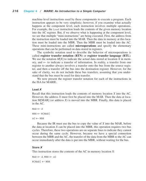
machine-level instructions used by these components <strong>to</strong> execute a program. Each<br />
instruction appears <strong>to</strong> be very simplistic; however, if you examine what actually<br />
happens at the component level, each instruction involves multiple operations.<br />
For example, the Load instruction loads the contents of the given memory location<br />
in<strong>to</strong> the AC register. But, if we observe what is happening at the component level,<br />
we see that multiple “mini-instructions” are being executed. First, the address from<br />
the instruction must be loaded in<strong>to</strong> the MAR. Then the data in memory at this location<br />
must be loaded in<strong>to</strong> the MBR. Then the MBR must be loaded in<strong>to</strong> the AC.<br />
These mini-instructions are called microoperations and specify the elementary<br />
operations that can be performed on data s<strong>to</strong>red in registers.<br />
The symbolic notation used <strong>to</strong> describe the behavior of microoperations is<br />
called register transfer notation (RTN) or register transfer language (RTL).<br />
We use the notation M[X] <strong>to</strong> indicate the actual data s<strong>to</strong>red at location X in memory,<br />
and ← <strong>to</strong> indicate a transfer of information. In reality, a transfer from one<br />
register <strong>to</strong> another always involves a transfer on<strong>to</strong> the bus from the source register,<br />
and then a transfer off the bus in<strong>to</strong> the destination register. However, for the<br />
sake of clarity, we do not include these bus transfers, assuming that you understand<br />
that the bus must be used for data transfer.<br />
We now present the register transfer notation for each of the instructions in<br />
the ISA for MARIE.<br />
Load X<br />
Recall that this instruction loads the contents of memory location X in<strong>to</strong> the AC.<br />
However, the address X must first be placed in<strong>to</strong> the MAR. Then the data at location<br />
M[MAR] (or address X) is moved in<strong>to</strong> the MBR. Finally, this data is placed<br />
in the AC.<br />
MAR ← X<br />
MBR ← M[MAR]<br />
AC ← MBR<br />
Because the IR must use the bus <strong>to</strong> copy the value of X in<strong>to</strong> the MAR, before<br />
the data at location X can be placed in<strong>to</strong> the MBR, this operation requires two bus<br />
cycles. Therefore, these two operations are on separate lines <strong>to</strong> indicate they cannot<br />
occur during the same cycle. However, because we have a special connection<br />
between the MBR and the AC, the transfer of the data from the MBR <strong>to</strong> the AC can<br />
occur immediately after the data is put in<strong>to</strong> the MBR, without waiting for the bus.<br />
S<strong>to</strong>re X<br />
This instruction s<strong>to</strong>res the contents of the AC in memory location X:<br />
MAR ← X, MBR ← AC<br />
M[MAR] ← MBR


