LEYBOLD DIDACTIC GMBH Gebrauchsanweisung 546 281 ...
LEYBOLD DIDACTIC GMBH Gebrauchsanweisung 546 281 ...
LEYBOLD DIDACTIC GMBH Gebrauchsanweisung 546 281 ...

You also want an ePaper? Increase the reach of your titles
YUMPU automatically turns print PDFs into web optimized ePapers that Google loves.
7/97-Sf-<br />
Physik Chemie ⋅ Biologie Technik <strong>LEYBOLD</strong> <strong>DIDACTIC</strong> <strong>GMBH</strong><br />
Der Geigersche Spitzenzähler (<strong>546</strong> <strong>281</strong>) wird bei Einführungsversuchen<br />
zur Radioaktivität eingesetzt (Nachweis von α- und<br />
β-Strahlung; Erklärung der Funktionsweise eines Auslösezählrohres).<br />
Die Ausgangsimpulse des Spitzenzählers werden entweder<br />
• von einem Wulf-Elektroskop (<strong>546</strong> 00) angezeigt<br />
oder<br />
• über den Adapter zum Spitzenzähler mit einem Oszilloskop<br />
sichtbar oder mit einem Leistungsverstärker (z.B. 522 61) mit<br />
angeschlossenem Lautsprecher (z.B. 587 08) hörbar gemacht.<br />
Literatur:<br />
Zentralkartei Radioaktive Strahlung (598 691)<br />
1 Sicherheitshinweise<br />
• Vorsicht beim Experimentieren mit Hochspannung!<br />
Spannungsführende metallische Teile nicht berühren!<br />
Gehäuse des Spitzenzählers erden!<br />
• Beim Umgang mit einem radioaktiven Präparat die ortsüblichen<br />
Sicherheitsvorschriften beachten.<br />
2 Beschreibung, technische Daten<br />
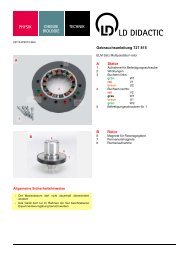
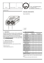
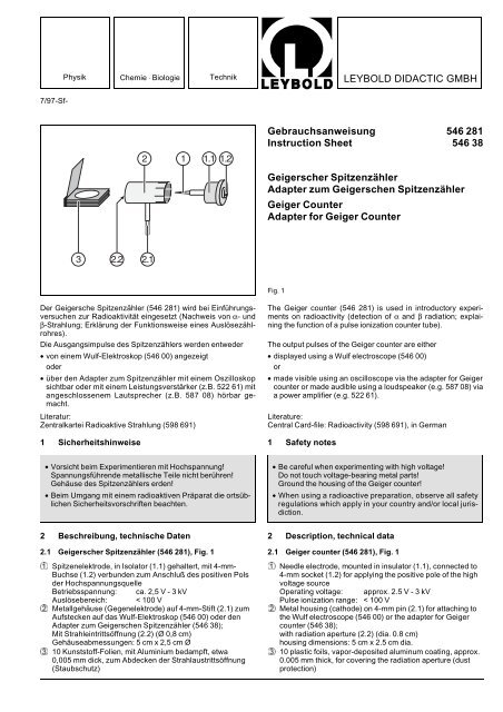
2.1 Geigerscher Spitzenzähler (<strong>546</strong> <strong>281</strong>), Fig. 1<br />
� Spitzenelektrode, in Isolator (1.1) gehaltert, mit 4-mm-<br />
Buchse (1.2) verbunden zum Anschluß des positiven Pols<br />
der Hochspannungsquelle<br />
Betriebsspannung: ca. 2,5 V - 3 kV<br />
Auslösebereich: < 100 V<br />
� Metallgehäuse (Gegenelektrode) auf 4-mm-Stift (2.1) zum<br />
Aufstecken auf das Wulf-Elektroskop (<strong>546</strong> 00) oder den<br />
Adapter zum Geigerschen Spitzenzähler (<strong>546</strong> 38);<br />
Mit Strahleintrittsöffnung (2.2) (Ø 0,8 cm)<br />
Gehäuseabmessungen: 5 cm x 2,5 cm Ø<br />
� 10 Kunststoff-Folien, mit Aluminium bedampft, etwa<br />
0,005 mm dick, zum Abdecken der Strahlaustrittsöffnung<br />
(Staubschutz)<br />
<strong>Gebrauchsanweisung</strong> <strong>546</strong> <strong>281</strong><br />
Instruction Sheet <strong>546</strong> 38<br />
Geigerscher Spitzenzähler<br />
Adapter zum Geigerschen Spitzenzähler<br />
Geiger Counter<br />
Adapter for Geiger Counter<br />
Fig. 1<br />
The Geiger counter (<strong>546</strong> <strong>281</strong>) is used in introductory experiments<br />
on radioactivity (detection of α and β radiation; explaining<br />
the function of a pulse ionization counter tube).<br />
The output pulses of the Geiger counter are either<br />
• displayed using a Wulf electroscope (<strong>546</strong> 00)<br />
or<br />
• made visible using an oscilloscope via the adapter for Geiger<br />
counter or made audible using a loudspeaker (e.g. 587 08) via<br />
a power amplifier (e.g. 522 61).<br />
Literature:<br />
Central Card-file: Radioactivity (598 691), in German<br />
1 Safety notes<br />
• Be careful when experimenting with high voltage!<br />
Do not touch voltage-bearing metal parts!<br />
Ground the housing of the Geiger counter!<br />
• When using a radioactive preparation, observe all safety<br />
regulations which apply in your country and/or local jurisdiction.<br />
2 Description, technical data<br />
2.1 Geiger counter (<strong>546</strong> <strong>281</strong>), Fig. 1<br />
� Needle electrode, mounted in insulator (1.1), connected to<br />
4-mm socket (1.2) for applying the positive pole of the high<br />
voltage source<br />
Operating voltage: approx. 2.5 V - 3 kV<br />
Pulse ionization range: < 100 V<br />
� Metal housing (cathode) on 4-mm pin (2.1) for attaching to<br />
the Wulf electroscope (<strong>546</strong> 00) or the adapter for Geiger<br />
counter (<strong>546</strong> 38);<br />
with radiation aperture (2.2) (dia. 0.8 cm)<br />
housing dimensions: 5 cm x 2.5 cm dia.<br />
� 10 plastic foils, vapor-deposited aluminum coating, approx.<br />
0.005 mm thick, for covering the radiation aperture (dust<br />
protection)
2.2 Adapter zum Geigerschen Spitzenzähler (<strong>546</strong> 38)<br />
� hochisolierte 4-mm-Buchse für Steckerstift (2.1) des Spitzenzählers<br />
(Impulseingang)<br />
� hochisolierte 4-mm-Impuls Ausgangsbuchse zum Anschluß<br />
des Signaleingangs eines Oszilloskops oder Verstärkers<br />
� Erdungsbuchse<br />
Gehäuseabmessungen: 13,5 cm x 7,5 cm x 5,5 cm<br />
3 Bedienung<br />
Zusätzlich erforderlich:<br />
Hochspannungsnetzgerät 10 kV 521 70<br />
Impulsindikator, z.B.<br />
Wulf-Elektroskop <strong>546</strong> 00<br />
oder<br />
Oszilloskop z.B. 575 211<br />
oder<br />
AC/DC-Verstärker 522 61<br />
mit Lautsprecher z.B. 587 08<br />
Empfehlenswerte Präparate<br />
Radiumpräparat 3,3 kBq 559 59<br />
Ra-226-Präparat 3,3 kBq 559 430<br />
Stativmaterial<br />
Spitzenelektrode � mit einem feuchten Lederlappen oder mit<br />
einer Flamme (nicht ausglühen!) sorgfältig von Staub u.ä. reinigen;<br />
Öffnung (2.2) nach dem Einsetzen der gereinigten Elektrode<br />
mit einer Folie (aus �) verschließen;<br />
Isolatoren der Buchsen (1.2) sowie � und � erforderlichenfalls<br />
mit einem nicht fasernden Lappen, der mit Spülmittel befeuchtet<br />
ist, reinigen; danach mit Warmluft trocknen;<br />
Anordnung gemäß Fig. 3 bzw. gemäß Fig. 4.1 oder Fig. 4.2<br />
aufbauen; positiven Pol der Hochspannungsquelle über Buchse<br />
(1.2) mit der Spitzenelektrode � verbinden.<br />
Einstellung der Impulsindikatoren:<br />
Wulf-Elektroskop: Gegenelektrode nahe an das Bändchen heran<br />
schieben;<br />
Oszilloskop: Vert. Input: AC<br />
Vert. Ampl.: 0,2 V cm -1 bis 2 V cm -1<br />
Timebase: 1 ms cm -1 bis 5 ms cm -1<br />
AC/DC-Verstärker: AC; Verstärkung x 1000<br />
Einstellung der optimalen Hochspannung:<br />
Bevor das Präparat vor die Strahleintrittsöffnung gebracht wird,<br />
Hochspannung sehr langsam bis genau auf den Wert erhöhen,<br />
bei dem selbständige Entladung einsetzt (angezeigt durch<br />
ständiges Ausschlagen des Blättchens an die Gegenelektrode<br />
des Wulf-Elektroskops sowie durch zahlreiche optische bzw.<br />
akustische Impulse auf dem Oszilloskop bzw. im Lautsprecher);<br />
danach Spannung um etwa 30 V - 50 V vermindern, so<br />
daß Entladung nur dann auftreten kann, wenn die Luft zwischen<br />
Spitzenelektrode und Gehäuse des Spitzenzählers<br />
durch radioaktive Strahlung ionisiert wird;<br />
empfehlenswerte Abstände zwischen Präparat und Strahleintrittsöffnung:<br />
ca. 1 cm bis 3 cm für α- und β-Strahlung, 3 cm bis<br />
6 cm für β-Strahlung;<br />
zum Nachweis von β-Teilchen Papier zwischen Präparat und<br />
Strahleintrittsöffnung halten, so daß die α-Strahlung abgeschirmt<br />
wird.<br />
2<br />
2.2 Adapter for Geiger counter (<strong>546</strong> 38)<br />
� Highly insulated 4-mm socket for plug pin (2.1) of Geiger<br />
counter (pulse input)<br />
� Highly insulated 4-mm pulse output socket for connecting<br />
the signal input of an oscilloscope or an amplifier<br />
� Ground socket<br />
Housing dimensions: 13.5 cm x 7.5 cm x 5.5 cm<br />
Fig. 2<br />
3 Operation<br />
Additionally required:<br />
High voltage power supply 10 kV 521 70<br />
Pulse indicator, e.g.<br />
Wulf electroscope <strong>546</strong> 00<br />
or<br />
Oscilloscope e.g. 575 211<br />
or<br />
AC/DC amplifier 522 61<br />
with loudspeaker e.g. 587 08<br />
Recommended preparations<br />
Radium preparation 3.3 kBq 559 59<br />
Ra-226 preparation 3.3 kBq 559 430<br />
Stand material<br />
Carefully clean needle electrode � of dust or similar using a<br />
damp leather rag or a flame (do not heat red-hot!). After inserting<br />
the clean needle, cover opening (2.2) with a foil (from �).<br />
If necessary, clean the insulators of sockets (1.2) as well as �<br />
and � using a lint-free cloth moistened with a little dish soap;<br />
dry the sockets with hot air.<br />
Set up the apparatus as shown in Fig. 3 resp. Fig. 4.1 or Fig.<br />
4.2. Connect the positive pole of the high-voltage source to the<br />
needle electrode � via socket (1.2).<br />
Setting up the pulse indicators:<br />
Wulf electroscope: slide the cathode close to the strip.<br />
Oscilloscope: vert. input: ac<br />
vert. ampl.: 0.2 v cm -1 to 2 v cm -1<br />
time base: 1 ms cm -1 to 5 ms cm -1<br />
AC/DC amplifier: AC; gain x 1000<br />
Setting the optimum high voltage:<br />
Before placing the preparation in front of the radiation aperture,<br />
increase the high voltage very slowly to exactly the value at<br />
which spontaneous discharge occurs (indicated by constant<br />
deflection of the leaf toward the cathode of the Wulf electroscope<br />
as well as by numerous optical or acoustic pulses on the<br />
oscilloscope or speaker respectively). Then reduce the voltage<br />
by about 30 V - 50 V so that discharge can only occur when the<br />
air between the needle electrode and the housing of the Geiger<br />
counter is ionized by radiation.<br />
Recommended distances between preparation and radiation<br />
aperture: approx. 1 cm to 3 cm for α and β radiation, 3 cm to<br />
6 cm for β radiation;<br />
To demonstrate β particles, hold a sheet of paper between preparation<br />
and radiation aperture to shield the α radiation.
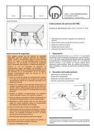
Fig. 3<br />
Nachweis von α- und β-Teilchen mit dem Wulf-Elektroskop (<strong>546</strong> 00)<br />
Demonstrating α and β particles with the Wulf electroscope (<strong>546</strong> 00)<br />
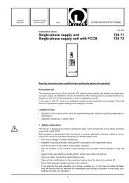
Fig. 4.1<br />
Optischer Nachweis von α- und β-Teilchen mit einem Oszilloskop;<br />
Betriebsspannung im Plateau der Zählrohr-Charakteristik: Anzeige von α- und β-Teilchen durch Impulse gleicher Höhe;<br />
Betriebsspannung im Proportionalbereich: energieanalytische Anzeige (niedrige Impulse durch β-Strahlung; hohe Impulse durch energiereichere<br />
α-Strahlung);<br />
empfehlenswert zur Einstellung der Hochspannung im sehr schmalen Proportionalbereich: Feineinstellung über 10-Gang-Potentiometer 1 kΩ<br />
(577 93)an Steuereingang �/� vornehmen (s. Nebenskizze sowie <strong>Gebrauchsanweisung</strong> 521 70).<br />
Optically demonstrating α and β particles with an oscilloscope<br />
Operating voltage in plateau of counter-tube characteristic: display of α and β particles by pulses of equal amplitude.<br />
Operating voltage in proportional range: energy-analytical display (low pulses due β radiation, high pulses due to higher-energy α radiation).<br />
Recommended for setting the high voltage in an extremely narrow proportional range: fine adjustment via 10-turn potentiometer 1 kΩ (577 93) at<br />
control input �/� (see inset drawing and Instruction Sheet 521 70).<br />
Fig. 4.2<br />
Akustischer Nachweis von α- und β-Teilchen über AC/DC-Verstärker<br />
(522 61) und Lautsprecher (587 08)<br />
Acoustically demonstrating α and β particles via AC/DC amplifier<br />
(522 61) and loudspeaker (587 08)<br />
<strong>LEYBOLD</strong> <strong>DIDACTIC</strong> <strong>GMBH</strong> ⋅ Leyboldstrasse 1 ⋅ D-50354 Hürth ⋅ Phone (02233) 604-0 ⋅ Telefax (02233) 604-222 ⋅ e-mail: info@leybold-didactic.de<br />
© by Leybold Didactic GmbH Printed in the Federal Republic of Germany<br />
Technical alterations reserved