Thermo Katalog - Lemo
Thermo Katalog - Lemo
Thermo Katalog - Lemo

Create successful ePaper yourself
Turn your PDF publications into a flip-book with our unique Google optimized e-Paper software.
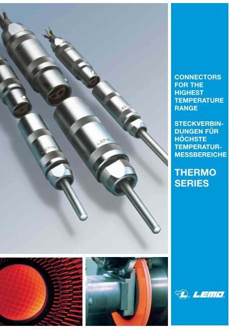
CONNECTORS<br />
FOR THE<br />
HIGHEST<br />
TEMPERATURE<br />
RANGE<br />
STECKVERBIN-<br />
DUNGEN FÜR<br />
HÖCHSTE<br />
TEMPERATUR-<br />
MESSBEREICHE<br />
THERMO<br />
SERIES
2<br />
Vacuumtest with<br />
leakdetector<br />
Vakuumtest mit<br />
Leakdetektor<br />
Vacuumtight sealed<br />
sockets with<br />
Ni-Cr/Ni contacts<br />
Hochvakuumdichte<br />
Apparatedosen mit<br />
Ni-Cr/Ni-Kontakten<br />
Crimping:<br />
coaxial, biaxial,<br />
triaxial, multipole<br />
Crimpen:<br />
koaxial, biaxial,<br />
triaxial, mehrpolig<br />
Insight of our production<br />
Einblicke in unsere Fertigung<br />
Cable<br />
assembling<br />
and system<br />
technology<br />
Konfektionieren<br />
von Steckverbindungen<br />
und<br />
Systemtechnologie<br />
Cable overmold<br />
technology<br />
Umspritzen für<br />
Kabelzugentlastungen<br />
Final inspection<br />
completely<br />
PC-organized<br />
Endkontrolle<br />
komplett<br />
PC-organisiert
Technische Information / Technical information<br />
Tabelle / Table / DIN-Information<br />
Bestellinformation / Order information<br />
Spannzangen-Übersicht / Collets table<br />
Bauform / Model<br />
TH-Kontaktfiguration / TH-Contact figuration<br />
TH-Spannzangen u. ISO / TH-Collets and insulators<br />
Bestellinformation / Order information<br />
Spannzangen-Übersicht / Collets table<br />
Bauform / Model<br />
TH-Spannzangen u. ISO / TH-Collets and insulators<br />
Bestellinformation / Order information<br />
Spannzangen-Übersicht / Collets table<br />
Bauform / Model<br />
TH-Kontaktfiguration / TH-Contact figuration<br />
TH-Spannzangen u. ISO / TH-Collets and insulators<br />
Konfektionierungen / Cable assembly<br />
Crimptechnik S/E Serie / Crimptechnique S/E Series<br />
Crimptechnik B/K Serie / Crimptechnique B/K Series<br />
<strong>Katalog</strong>übersicht / Catalog summary<br />
Contents<br />
Inhaltsverzeichnis<br />
Serie / Series<br />
S<br />
S<br />
S<br />
S + E<br />
S<br />
E<br />
E<br />
E<br />
E<br />
B<br />
B<br />
B<br />
B<br />
B<br />
S + E<br />
B + K<br />
3<br />
Seite / Page<br />
4 – 7<br />
8 – 9<br />
10<br />
11 – 13<br />
14 – 17<br />
18<br />
19 – 25<br />
26<br />
27<br />
28 – 30<br />
31<br />
32<br />
33<br />
34 – 36<br />
37<br />
38 – 40<br />
41<br />
42 – 46<br />
47 – 50<br />
51
4<br />
Technical information<br />
Technische Information<br />
Messwiderstande,Widerstandsthermometer,<br />
Ausgleichsleitungen, Mantelleitungen<br />
und vor allen Dingen Mantel-<br />
<strong>Thermo</strong>elemente müssen für den industriellen<br />
Einsatz mit einer geeigneten<br />
Steckverbindung versehen werden.<br />
Das Messen der <strong>Thermo</strong>spannung erfolgt<br />
in mV und μV. Für diesen Messbereich<br />
ist die LEMO-Steckverbindung<br />
das ideale Bauteil.<br />
Mantel-<strong>Thermo</strong>elemente,<br />
Aufbau und Funktion<br />
Miniatur-Mantel-<strong>Thermo</strong>elemente bestehen<br />
aus einem <strong>Thermo</strong>paar, eingebettet<br />
in einer hochtemperaturfesten keramischen<br />
Isolationsschicht, umgeben von<br />
einem Metallmantel, der als Schutz<br />
gegen mechanische und chemische<br />
Einwirkungen dient.<br />
Der Aufbau und die Funktion von Mantel-<strong>Thermo</strong>elementen<br />
ist bis hin zu<br />
Steckverbindungen in der DIN 4370,<br />
43721, I.E.C.584 1, 2 und 4, festgehalten.<br />
Measure resistances, resistance thermometers,<br />
compensation cables, insulated<br />
cables and particularly insulated<br />
thermocouples must be fitted with a<br />
suitable connector for the industrial use.<br />
The thermovoltage is measured in mV<br />
and μV. The LEMO connector is the<br />
ideal construction part for this technology.<br />
Jacket thermocouples,<br />
construction and function<br />
Miniature jacket thermocouples consist<br />
of a thermo pair fitted in an high temperature<br />
ceramic insulation material coated<br />
with a metallic jacket, saved against<br />
mechanical and chemical effects.<br />
The construction and the function of the<br />
thermocouples and the parts of the connector<br />
are normed in DIN 4370, 43721,<br />
I.E.C.584 1, 2 and 4.
Die Auswahl des Adermaterials<br />
bestimmt den Temperaturbereich.<br />
Mit TH-<strong>Thermo</strong>elementen sind Messungen<br />
zwischen - 250 und + 2200 °C<br />
möglich. Die Entwicklung für neue<br />
Werkstoffe, seit der Einführung durch<br />
SEEBECK und PELTIR, ist noch immer<br />
in Bewegung.<br />
Das gebräuchlichste <strong>Thermo</strong>paar ist die<br />
Ausführung Chromel-Alumel (Typ K).<br />
Der Einsatzbereich liegt bei - 200 bis<br />
1100 °C. In Verbindung mit unserer<br />
LEMO Steckverbindung erhält man hier<br />
gute thermoelektrische Eigenschaften,<br />
und der <strong>Thermo</strong>-Spannungsverlauf ist<br />
fast linear.<br />
<strong>Thermo</strong>spannung (mV)<br />
E.m.f. E m f . (mV) ( ( V) )<br />
80<br />
70<br />
60<br />
50<br />
40<br />
30<br />
20<br />
10<br />
0<br />
Steckverbindung und<br />
<strong>Thermo</strong>element<br />
42.283 42 422.283 2 283 283 mV<br />
mV<br />
J<br />
68.783 68 6 68.783 68 8 7 7783<br />
8 83 833 m mV V<br />
E<br />
Die Entfernung zwischen der Meßstelle<br />
und dem Messgerät beträgt in extremen<br />
Fällen mehrere 100 m.<br />
Technical information<br />
Technische Information<br />
The part of the wire material will choosed<br />
the temperature range.<br />
The measurements of thermocouples is<br />
between - 250 and + 2200 °C.<br />
The development of new materials is<br />
still moving since the introduction of<br />
SEEBECK and PELTIR.<br />
The most used thermocouple is the part<br />
of Chromel-Alumel (type K). The temperature<br />
range is from - 200 to 1100 °C.<br />
With our LEMO connector we reached<br />
good thermoelectric characteristics. The<br />
thermoelectric power curve is nearly<br />
linear.<br />
<strong>Thermo</strong>electric power (mV)<br />
48.828 48 4 48 8 8 828 2 8 m mV mmV<br />
V<br />
K<br />
47.502 47 502 2 mV<br />
mV<br />
N<br />
18.842 18 188.842 8 842 842 mV<br />
mV<br />
R<br />
16.771 16 16.771 6.771 6 771<br />
771 mV mmV<br />
m mV<br />
m V<br />
S<br />
12.426 12 1 12 2 2. 4426<br />
426 2 26<br />
m mmV<br />
mV V<br />
B<br />
35.932 35 5.932 5 932 932 mV<br />
mmV<br />
mmV<br />
m<br />
C<br />
Temperatur T e m mp<br />
e eeratur<br />
ra<br />
t t u ur<br />
(<br />
(<br />
( °C) C)<br />
Connector and thermocouple<br />
In extreme cases the distance between<br />
the measuring point and the gauge can<br />
be several hundred meters.<br />
5
6<br />
Technical information<br />
Technische Information<br />
Messaufbau<br />
Mantelthermoelement<br />
Um eine einwandfreie Funktion der<br />
Miniatur-Mantel-<strong>Thermo</strong>elemente zu<br />
gewährleisten, müssen die Anschlußstellen<br />
gegen Feuchtigkeit dicht abgeschlossen<br />
werden. Dies geschieht<br />
durch Vergießen mit Kunststoffen. Hier<br />
hat sich insbesondere das Vergußmaterial<br />
STYCAST mit einem Temperaturbereich<br />
von 73 bis 177 °C, bewährt.<br />
TH-Spannzangen mit Vergußstelle<br />
-<br />
+<br />
Ausgleichsleitung<br />
Steckverbindung<br />
Measurement assembly<br />
Meßgerät<br />
mV<br />
Vergleichsstelle<br />
To guarantee a good function of the<br />
insulated miniature thermocouples, the<br />
connection points must be tightly saved<br />
against humity. This sealing can be<br />
made with plastic materials, especially<br />
STYCAST which has a temperature<br />
variation from 73 to 177 °C.<br />
TH-collets with sealing point<br />
Stycast
Aus langen Erfahrungswerten geht hervor,<br />
daß bei den gebräuchlichsten<br />
<strong>Thermo</strong>paaren, wie z. B. Chromel-<br />
Alumel, die hochwertigen LEMO-Kontakte<br />
in der spezial vergoldeten Version<br />
eingesetzt werden können. An der<br />
Anschlußstelle mit dem <strong>Thermo</strong>elementmaterial<br />
hebt sich die EMK (elektromagnetische<br />
Kraft) vollständig auf.<br />
Dies ist aber nur der Fall, wenn die<br />
Steckverbindung als Zwischenstück in<br />
der <strong>Thermo</strong>leitung dient und diese sich<br />
wiederum auf einem gleichbleibenden<br />
Temperaturlevel befindet. Überall dort,<br />
wo ein thermisches Gleichgewicht der<br />
Steckverbindung nicht erreicht wird,<br />
muß der Steckkontakt aus demselben<br />
Material, wie das der <strong>Thermo</strong>elemente,<br />
gewählt werden. Siehe Tabelle <strong>Thermo</strong>elemente-Ausgleichskabel.<br />
Bei der Verwendung von Steckverbindungen<br />
mit <strong>Thermo</strong>kontakten ist auf<br />
den richtigen Anschluß nach DIN 43711,<br />
A.N.S.I. MC 96.1, zu achten.<br />
Siehe Tabelle nach Farbcode und<br />
+/- Einteilung.<br />
Wir empfehlen nachstehendes<br />
Lötzinn:<br />
Bei der Verwendung von Lötzinn, Typ<br />
HMP07, und der richtigen Löttemperatur<br />
(380 °C), ist eine leichte Verarbeitung<br />
und ein homogener Anschluß gewährleistet.<br />
Entspricht laut Freistellung der<br />
ISO 14001.<br />
Das Mantel-<strong>Thermo</strong>element wird in der<br />
Regel an der Kupplung, Typ PCA.- - -,<br />
oder an der Apparatedose mit Zugentlastung,<br />
Typ PSA. - - -, angeschlossen.<br />
Der Anschluß der Ausgleichsleitung<br />
erolgt somit am Slecker mit der Push-<br />
Pull-Verriegelung, Typ FFA. - - -.<br />
Technical information<br />
Technische Information<br />
During many years of experience, we<br />
can assert that LEMO contacts of high<br />
quality in the special golden version can<br />
be mounted on the most used thermocouples,<br />
for example Chromel-Alumel.<br />
At the connection point with the thermocouple<br />
material neutralizes the e.m.f.<br />
(electromagnetic force). This is only the<br />
case, when the connector like an intermediate<br />
piece in the thermoelectric wire<br />
works. The system must be on a constant<br />
temperature level. Wherever we<br />
don’t reach a thermal balance of the<br />
connector, the contact should be from<br />
the same material as the thermocouple.<br />
See table thermoelement compensation<br />
cable.<br />
If you use connectors with thermocontacts,<br />
you must pay attention to the<br />
assembly according to DIN 43711,<br />
A.N.S.I. MC 96.1.<br />
See following table code colours<br />
and +/- splitting.<br />
We recommend following solder<br />
tin:<br />
When you work with solder tin of type<br />
HMP07 and the right soldering temperature<br />
(380 °C), an easy working and a<br />
homogeneous connection can be<br />
guaranteed. According to release<br />
of ISO 14001.<br />
The jacket thermocouple will be usually<br />
connected to the free socket of type<br />
PCA. - - - or to the receptacle with<br />
cable collet type PSA. - - -.<br />
The compensation cable is consequently<br />
fitted at the connector with<br />
Push-Pull locking system,<br />
type FFA. - - -.<br />
7
8<br />
+ – Table<br />
+ – Tabelle<br />
<strong>Thermo</strong>element Ausgleichskabel<br />
Typ / Model Polung / Pole Material Polung / Pole Material<br />
B<br />
E<br />
J<br />
K<br />
L<br />
N<br />
R<br />
S<br />
T<br />
U<br />
+ Platin, 30% Rodium + Cu-Legierung<br />
– Platin, 6% Rodium – Cu<br />
+ Nickel-Chrom + NiCr<br />
(Chromel)<br />
– Kupfer-Nickel – CuNi<br />
(Konstantan)<br />
+ Eisen + Fe<br />
– Kupfer-Nickel – CuNi<br />
(Konstantan)<br />
+ Nickel-Chrom + NiCr + Fe<br />
(Chromel)<br />
– Nickel – Ni – CuNi<br />
(Alumel)<br />
+ Eisen + Fe<br />
– Kupfer-Nickel – CuNi<br />
(Konstantan)<br />
+ Nickel-Chrom-Silizium + NiCrSi + Cu<br />
(Nicrosil)<br />
– Nickel-Silizium – NiSi – CuNi<br />
(Nisil)<br />
+ Platin, 13% Rodium + Cu<br />
– Platin – CuNi<br />
+ Platin, 10% Rodium + Cu<br />
– Platin – CuNi<br />
+ Kupfer + Cu<br />
– Kupfer-Nickel – CuNi<br />
(Konstantan)<br />
+ Kupfer + Cu<br />
– Kupfer-Nickel – CuNi<br />
(Konstantan)
Die gebräuchlichsten Ausgleichskabel<br />
(vor Dezember 1993)<br />
Ab Dezember 1993 sind die unterschiedlichen<br />
Normen, NF C 42-324, DIN<br />
43714 (ausgenommen Typ L) BS 1843<br />
und ANSI MC 96.1 in den internationalen<br />
Standards IEC 584-3 und der DIN<br />
43722 zusammengefasst.<br />
Farbcode Tabelle nach DIN 43714,<br />
NFC 42.324, BS 1843 und ANSI MC 96.1<br />
The common compensation<br />
cables (before december 1993)<br />
Typ Standards Mantel Seele + Seele –<br />
Model (Sheath) (Wire +) (Wire –)<br />
K NF + –<br />
K DIN + –<br />
K BS + –<br />
K ANSI + –<br />
J NF + –<br />
L DIN + –<br />
J BS + –<br />
J ANSI + –<br />
E NF + –<br />
T NF + –<br />
T DIN + –<br />
S NF + –<br />
Different norms as NF C 42-324, DIN<br />
43714 (except type no. L), BS 1843 and<br />
ANSI MC 96.1 are summarised in the<br />
international standard IEC 584-3 and<br />
DIN 43722 since December 1993.<br />
Typ Standards Mantel Seele + Seele –<br />
Model (Sheath) (Wire +) (Wire –)<br />
IEC 584-3<br />
K DIN 43722<br />
+ –<br />
IEC 584-3<br />
J DIN 43722<br />
+ –<br />
IEC 584-3<br />
E DIN 43722<br />
+ –<br />
IEC 584-3<br />
T DIN 43722<br />
+ –<br />
IEC 584-3<br />
S DIN 43722<br />
+ –<br />
9
10<br />
Order information S Series standard<br />
Bestellinformation S Serie Standard<br />
Konstruktions-lnformation Constructions information<br />
S Serie Standard S Series standard<br />
6 2 3 1 4 5 8 7<br />
1 7 6 5 4 2 8 3<br />
Fixed socket<br />
1 Outer shell 5 Locking washer<br />
2 Earthing crown 6 Insulator<br />
3 Retaining ring 7 Male contact<br />
4 Hexagonal nut 8 Female contact<br />
Model (page 14 – 17)<br />
Size and Series (page 14 – 17)<br />
Contact figuration<br />
(page 18 + 41, 19 – 25)<br />
Housing<br />
Please see Unipole/Multipole catalogue<br />
Insulator<br />
Please see Unipole/Multipole catalogue<br />
Model (page 14 – 17)<br />
Size and Series (page 14 – 17)<br />
Contact figuration<br />
(page 18 + 41, 19 – 25)<br />
Bestellbeispiele Part number example<br />
Standardstecker, gerade Straight standard plug<br />
Standardstecker gerade, Größe 0, S Serie<br />
mehrpolig (2 Kontakte), Außenkörper aus<br />
Messing, Isolationsteil aus PEEK, männlicher<br />
und weiblicher Lötkontakt, Spannzange für<br />
geschirmtes Kabel, Durchmesser 3,2 mm.<br />
FFA 0S 302 C L A L 32 Z N<br />
Apparatedose Socket<br />
ERA 2S 302 C L L<br />
Einbauapparatedose, Größe 2, S Serie, mehrpolig<br />
(2 Kontakte), Außenkörper aus Messing,<br />
verchromt, Massekrone vernickelt, Isolationsteil<br />
aus PEEK, männlicher und weiblicher Lötkontakt.<br />
Straight plug<br />
1 Outer shell 5 Insulator<br />
2 Latch sleeve 6 Male contact<br />
3 Collet nut 7 Female contact<br />
4 Centre-piece 8 Collet<br />
Straight plug, size 0, S Series, 2 contacts,<br />
chromed brass shell, PEEK insulator, male and<br />
female solder contact, collet 3,2 mm for shielded<br />
cable.<br />
Fixed socket, size 2, S Series, 2 contacts, chromed<br />
brass shell, PEEK insulator, female and<br />
male solder contact.<br />
Bend relief and Color<br />
Please see Unipole/Multipole catalogue<br />
Collet nut for bend relief<br />
Please see Unipole/Multipole catalogue<br />
Collet-Ø<br />
(page 11 – 13, 19 – 25)<br />
Collet Type<br />
(page 11 – 13, 19 – 25)<br />
Contact (page 18 + 41)<br />
Variant<br />
Contact (page 18 + 41)<br />
Insulator<br />
Please see Unipole/Multipole catalogue<br />
Housing<br />
Please see Unipole/Multipole catalogue
S Series – Size 0<br />
S Serie – Größe 0<br />
Reference<br />
Model Ø<br />
C = AG<br />
Series<br />
Ø B<br />
Ø A<br />
Ø Collet Ø Cable<br />
(mm) (mm)<br />
ØA ØB max. min.<br />
L = NG<br />
Collets table<br />
Spannzangen-Übersicht<br />
Ø A<br />
K = Adapter to the next size<br />
11<br />
Part number Re- Part number Part number<br />
collet marks adapter Collet nut<br />
1) 2) 2)<br />
C 17 1,7 — 1,6 1,3 FFA.0S.717.CN B<br />
C 22 2,2 — 2,1 1,7 FFA.0S.722.CN B<br />
C 27 2,7 — 2,6 2,2 FFA.0S.727.CN b<br />
C 32 3,2 — 3,1 2,7 FFA.0S.732.CN b<br />
C 37 3,7 3,2 3,6 3,0 FFA.0S.737.CN b<br />
C 42 4,2 3,7 4,1 3,3 FFA.0S.742.CN b<br />
C 44 4,4 3,7 4,3 3,5 FFA.0S.744.CN b 4) FFA.0S.133.LC<br />
C 50 5,1 5,1 5,0 4,4 FFA.0S.750.CN b 4) FFA.0S.133.LC<br />
K 47 4,7 — 4,6 3,8 FFA.1S.747.CN b FFA.0S.137.LCN FFA.1S.130.LC<br />
K 52 5,2 — 5,1 4,3 FFA.1S.752.CN b FFA.0S.137.LCN FFA.1S.130.LC<br />
K 57 5,7 — 5,6 4,8 FFA.1S.757.CN b FFA.0S.137.LCN FFA.1S.130.LC<br />
K 62 6,2 5,2 6,1 5,3 FFA.1S.762.CN b FFA.0S.137.LCN FFA.1S.130.LC<br />
K 66 6,6 5,5 6,5 5,9 FFA.1S.766.CN B FFA.0S.137.LCN FFA.1S.130.LC<br />
K 68 0S 6,8 5,5 6,7 6,0 FFA.1S.768.CN b FFA.0S.137.LCN FFA.1S.130.LC<br />
C 17 1,7 — 1,6 1,3 FLA.0S.717.CN b 3)<br />
C 22 2,2 — 2,1 1,7 FLA.0S.722.CN b 3)<br />
C 27 2,7 — 2,6 2,2 FLA.0S.727.CN b 3)<br />
C 32 3,2 — 3,1 2,7 FLA.0S.732.CN b 3)<br />
C 37 3,7 3,2 3,6 3,0 FLA.0S.737.CN b 3)<br />
C 42 4,2 3,7 4,1 3,3 FLA.0S.742.CN b 3)<br />
C 44 4,4 3,7 4,3 3,5 FLA.0S.744.CN b 3)<br />
L 17 1,7 — 1,6 1,3 FFA.0S.717.LN b<br />
L 22 2,2 — 2,1 1,8 FFA.0S.722.LN b<br />
L 27 2,7 — 2,6 2,3 FFA.0S.727.LN b<br />
L 32 3,2 — 3,1 2,8 FFA.0S.732.LN b<br />
L 37 3,7 — 3,6 3,0 FFA.0S.737.LN b<br />
L 42 4,2 — 4,1 3,3 FFA.0S.742.LN b<br />
L 48 4,8 — 4,7 4,4 FFA.0S.748.LN b 4) FFA.0S.133.LC<br />
1) Für Einzelbestellung der Spannzangen.<br />
2) Für Einzelbestellung einer Spannzange der Type K benötigt man<br />
je einen Adapter und eine Spannschraube (Bestell-Nr. siehe oben).<br />
3) Diese Spannzange paßt zu den Typen FLA, FFP und PCP.<br />
4) Diese Spannzangen können nicht in Bauformen mit Spannschrauben<br />
für Knickschutztüllen verwendet werden.<br />
b lieferbar<br />
B auf Anfrage<br />
1) For individual orders of collets.<br />
2) For individual orders of a collet type K an adapter each is required as<br />
well as a collet nut (part number is mentioned above).<br />
3) This collet is used for the FLA, FFP and PCP models.<br />
4) These collets cannot be used for connector models with nut for fitting<br />
a bend relief.<br />
b in stock<br />
B on request
12<br />
S Series – Size 1<br />
S Serie – Größe 1<br />
Reference<br />
Model Ø<br />
Series<br />
Collets table<br />
Spannzangen-Übersicht<br />
C = AG<br />
Ø B<br />
Ø A<br />
Ø Collet Ø Cable<br />
(mm) (mm)<br />
ØA ØB max. min.<br />
L = NG<br />
Ø A<br />
K = Adapter to the next size<br />
Part number Re- Part number Part number<br />
collet marks adapter Collet nut<br />
1) 2) 2)<br />
C 17 1,7 — 1,6 1,3 FFA.1S.717.CN B FFA.1S.130.LC<br />
C 22 2,2 — 2,1 1,7 FFA.1S.722.CN b FFA.1S.130.LC<br />
C 27 2,7 — 2,6 2,2 FFA.1S.727.CN b FFA.1S.130.LC<br />
C 32 3,2 — 3,1 2,6 FFA.1S.732.CN b FFA.1S.130.LC<br />
C 37 3,7 — 3,6 2,7 FFA.1S.737.CN b FFA.1S.130.LC<br />
C 42 4,2 — 4,1 3,3 FFA.1S.742.CN b FFA.1S.130.LC<br />
C 47 4,7 — 4,6 3,8 FFA.1S.747.CN b FFA.1S.130.LC<br />
C 52 5,2 — 5,1 4,3 FFA.1S.752.CN b FFA.1S.130.LC<br />
C 57 5,7 — 5,6 4,8 FFA.1S.757.CN b FFA.1S.130.LC<br />
C 62 6,2 5,2 6,1 5,3 FFA.1S.762.CN b FFA.1S.130.LC<br />
C 66 6,6 5,5 6,5 5,9 FFA.1S.766.CN b 4) FFA.1S.131.LC<br />
C 68 6,8 5,5 6,7 6,0 FFA.1S.768.CN b 4) FFA.1S.131.LC<br />
K 72 7,2 6,7 7,0 6,1 FFA.2S.772.CN b FFA.1S.137.LCN FFA.2S.130.LC<br />
K 77 7,7 6,7 7,5 7,1 FFA.2S.777.CN B FFA.1S.137.LCN FFA.2S.130.LC<br />
K 82 8,2 6,7 8,0 7,6 FFA.2S.782.CN B FFA.1S.137.LCN FFA.2S.130.LC<br />
K 87 8,7 6,7 8,5 8,1 FFA.2S.787.CN B FFA.1S.137.LCN FFA.2S.130.LC<br />
C 17 1,7 — 1,6 1,3 FLA.1S.717.CN b 3) FFA.1S.130.LC<br />
C 22 2,2 — 2,1 1,7 FLA.1S.722.CN b 3) FFA.1S.130.LC<br />
C 27 2,7 — 2,6 2,2 FLA.1S.727.CN b 3) FFA.1S.130.LC<br />
C 32 3,2 — 3,1 2,6 FLA.1S.732.CN b 3) FFA.1S.130.LC<br />
C 37 1S 3,7 — 3,6 2,7 FLA.1S.737.CN b 3) FFA.1S.130.LC<br />
C 42 4,2 — 4,1 3,3 FLA.1S.742.CN b 3) FFA.1S.130.LC<br />
C 47 4,7 — 4,6 3,8 FLA.1S.747.CN b 3) FFA.1S.130.LC<br />
C 52 5,2 — 5,1 4,3 FLA.1S.752.CN b 3) FFA.1S.130.LC<br />
C 57 5,7 — 5,6 4,8 FLA.1S.757.CN b 3) FFA.1S.130.LC<br />
C 62 6,2 5,2 6,1 5,3 FLA.1S.762.CN b 3) FFA.1S.130.LC<br />
C 66 6,6 5,5 6,5 5,9 FLA.1S.766.CN b 3) FFA.1S.131.LC<br />
C 68 6,8 5,5 6,7 6,0 FLA.1S.768.CN b 3) FFA.1S.131.LC<br />
L 17 1,7 — 1,6 1,3 FFA.1S.717.LN b FFA.1S.130.LC<br />
L 22 2,2 — 2,1 1,7 FFA.1S.722.LN b FFA.1S.130.LC<br />
L 27 2,7 — 2,6 2,2 FFA.1S.727.LN b FFA.1S.130.LC<br />
L 32 3,2 — 3,1 2,6 FFA.1S.732.LN b FFA.1S.130.LC<br />
L 37 3,7 — 3,6 2,7 FFA.1S.737.LN b FFA.1S.130.LC<br />
L 42 4,2 — 4,1 3,3 FFA.1S.742.LN b FFA.1S.130.LC<br />
L 47 4,7 — 4,6 3,8 FFA.1S.747.LN b FFA.1S.130.LC<br />
L 50 5,0 — 4,9 4,7 FFA.1S.750.LN b FFA.1S.130.LC<br />
L 52 5,2 — 5,1 4,3 FFA.1S.752.LN b FFA.1S.130.LC<br />
L 57 5,7 — 5,6 4,8 FFA.1S.757.LN b FFA.1S.130.LC<br />
L 62 6,2 — 6,1 5,3 FFA.1S.762.LN b FFA.1S.130.LC<br />
L 66 6,6 — 6,5 5,9 FFA.1S.766.LN b 4) FFA.1S.131.LC<br />
1) Für Einzelbestellung der Spannzangen.<br />
2) Für Einzelbestellung einer Spannzange der Type K benötigt man<br />
je einen Adapter und eine Spannschraube (Bestell-Nr. siehe oben).<br />
3) Diese Spannzange paßt zu Type FLA.<br />
4) Diese Spannzangen können nicht in Bauformen mit Spannschrauben<br />
für Knickschutztüllen verwendet werden.<br />
b lieferbar<br />
B auf Anfrage<br />
1) For individual orders of collets.<br />
2) For individual orders of a collet type K an adapter each is required as<br />
well as a collet nut (part number is mentioned above).<br />
3) This collet is used for the FLA models.<br />
4) These collets cannot be used for connector models with nut for fitting<br />
a bend relief.<br />
b in stock<br />
B on request
S Series – Size 2<br />
S Serie – Größe 2<br />
Reference<br />
Model Ø<br />
C = AG<br />
Series<br />
Ø B<br />
Ø A<br />
Ø Collet Ø Cable<br />
(mm) (mm)<br />
ØA ØB max. min.<br />
L = NG<br />
Collets table<br />
Spannzangen-Übersicht<br />
Ø A<br />
K = Adapter to the next size<br />
13<br />
Part number Re- Part number Part number<br />
collet marks adapter Collet nut<br />
1) 2) 2)<br />
C 17 1,7 – 1,5 1,3 FFA.2S.717.CN B FFA.2S.130.LC<br />
C 27 2,7 – 2,5 1,7 FFA.2S.727.CN B FFA.2S.130.LC<br />
C 32 3,2 – 3,0 2,5 FFA.2S.732.CN B FFA.2S.130.LC<br />
C 42 4,2 – 4,0 3,1 FFA.2S.742.CN b FFA.2S.130.LC<br />
C 52 5,2 – 5,0 4,1 FFA.2S.752.CN b FFA.2S.130.LC<br />
C 62 6,2 – 6,0 5,1 FFA.2S.762.CN b FFA.2S.130.LC<br />
C 72 7,2 6,7 7,0 6,1 FFA.2S.772.CN b FFA.2S.130.LC<br />
C 77 7,7 6,7 7,5 7,1 FFA.2S.777.CN b FFA.2S.130.LC<br />
C 82 8,2 6,7 8,0 7,6 FFA.2S.782.CN B FFA.2S.130.LC<br />
C 87 8,7 6,7 8,5 8,1 FFA.2S.787.CN B FFA.2S.130.LC<br />
K 92 9,2 8,7 9,0 8,1 FFA.3S.792.CN b FFA.2S.137.LCN FFA.3S.130.LC<br />
K 97 9,7 8,7 9,5 9,1 FFA.3S.797.CN b FFA.2S.137.LCN FFA.3S.130.LC<br />
K 10 10,2 8,7 10,0 9,6 FFA.3S.710.CN b FFA.2S.137.LCN FFA.3S.130.LC<br />
K 11 10,7 8,7 10,5 10,1 FFA.3S.711.CN b FFA.2S.137.LCN FFA.3S.130.LC<br />
C 17 1,7 – 1,5 1,3 FLA.2S.717.CN b 3) FFA.2S.130.LC<br />
C 27 2,7 – 2,5 1,7 FLA.2S.727.CN b 3) FFA.2S.130.LC<br />
C 32 3,2 – 3,0 2,5 FLA.2S.732.CN b 3) FFA.2S.130.LC<br />
C 42 2S 4,2 – 4,0 3,1 FLA.2S.742.CN b 3) FFA.2S.130.LC<br />
C 52 5,2 – 5,0 4,1 FLA.2S.752.CN b 3) FFA.2S.130.LC<br />
C 62 6,2 – 6,0 5,1 FLA.2S.762.CN b 3) FFA.2S.130.LC<br />
C 72 7,2 6,7 7,0 6,1 FLA.2S.772.CN b 3) FFA.2S.130.LC<br />
C 77 7,7 6,7 7,5 7,1 FLA.2S.777.CN b 3) FFA.2S.130.LC<br />
L 82 8,2 6,7 8,0 7,6 FLA.2S.782.CN b 3) FFA.2S.130.LC<br />
L 87 8,7 6,7 8,5 8,1 FLA.2S.787.CN b 3) FFA.2S.130.LC<br />
L 27 2,7 – 2,5 1,7 FFA.2S.727.LN b FFA.2S.130.LC<br />
L 32 3,2 – 3,0 2,5 FFA.2S.732.LN b FFA.2S.130.LC<br />
L 42 4,2 – 4,0 3,1 FFA.2S.742.LN b FFA.2S.130.LC<br />
L 52 5,2 – 5,0 4,1 FFA.2S.752.LN b FFA.2S.130.LC<br />
L 62 6,2 – 6,0 5,1 FFA.2S.762.LN b FFA.2S.130.LC<br />
L 72 7,2 – 7,0 6,1 FFA.2S.772.LN b FFA.2S.130.LC<br />
L 77 7,9 – 7,5 7,1 FFA.2S.777.LN b FFA.2S.130.LC<br />
L 82 8,2 6,7 8,0 7,6 FFA.2S.782.LN b FFA.2S.130.LC<br />
L 87 8,7 – 8,5 7,8 FFA.2S.787.LN b FFA.2S.130.LC<br />
1) Für Einzelbestellung der Spannzangen.<br />
2) Für Einzelbestellung einer Spannzange der Type K benötigt man<br />
je einen Adapter und eine Spannschraube (Bestell-Nr. siehe oben).<br />
3) Diese Spannzange paßt zu Type FLA.<br />
b lieferbar<br />
B auf Anfrage<br />
1) For individual orders of collets.<br />
2) For individual orders of a collet type K an adapter each is required as<br />
well as a collet nut (part number is mentioned above).<br />
3) This collet is used for the FLA models.<br />
b in stock<br />
B on request
14<br />
S Series – standard<br />
S Serie – Standard<br />
~H<br />
Ø C<br />
Ø C<br />
Ø C<br />
M<br />
L<br />
S 2<br />
S 2<br />
S 2<br />
Model S Series<br />
Bauform S Serie<br />
~M<br />
~M<br />
~L<br />
~L<br />
A<br />
Ø A<br />
Ø A<br />
Model 1 Model 2<br />
Andere mechanische Bauformen siehe Unipole/Multipole <strong>Katalog</strong><br />
Other mechanical designs see Unipole/Multipole catalogue<br />
A1<br />
S 1<br />
Standard plug<br />
Standardstecker<br />
Reference<br />
Model Series<br />
Dimensions (mm)<br />
A C L M S2<br />
FFA 0S 9.0 4.2 34.5 24.5 6.5<br />
FFA 1S 12.0 6.2 42.5 31.5 8.5<br />
FFA 2S 14.8 8.5 52.0 40.0 11.0<br />
Standard plug with cable collet and nut for fitting<br />
a strain relief<br />
Standardstecker mit Knickschutzschraube<br />
Reference<br />
Model Series<br />
Dimensions (mm)<br />
A C L M S2<br />
FFA 0S 9.0 4.2 36.5 26.5 7<br />
FFA 1S 12.0 6.2 45.0 34.0 9<br />
FFA 2S 14.8 8.5 54.5 42.5 12<br />
Elbow plug (90°)<br />
Winkelstecker (90°)<br />
Reference<br />
Model Series<br />
Dimensions (mm)<br />
A A1 C H L M S1 S2<br />
FLA 0S 13 13 4.2 24.5 23.0 13.0 8 6.5<br />
FLA 1S 16 16 6.2 28.5 26.5 15.5 10 8.5<br />
FLA 2S 20 20 8.5 37.0 31.0 19.0 13 11.0<br />
Model 1: for unipole and coaxial types<br />
Model 2: for all other types<br />
Modell 1: für einpolige und koaxiale Typen<br />
Modell 2: für alle anderen Typen
Ø B<br />
Ø B<br />
Ø B<br />
e<br />
e<br />
S 3<br />
L maxi<br />
E maxi<br />
Multipole<br />
S 3<br />
L maxi<br />
S 3<br />
L maxi<br />
S 1 E maxi<br />
M<br />
S 1<br />
E maxi<br />
Multipole<br />
Andere mechanische Bauformen siehe Unipole/Multipole <strong>Katalog</strong><br />
Other mechanical designs see Unipole/Multipole catalogue<br />
M<br />
e<br />
M<br />
Ø A<br />
Ø A<br />
Ø A<br />
S 1<br />
Model S Series<br />
Bauform S Serie<br />
Plug with visible shell, non latching<br />
Positive Apparatedose (Einbaustecker)<br />
Reference<br />
Model Series<br />
Fixed socket<br />
Einbauapparatedose<br />
Dimensions (mm)<br />
15<br />
A B e E L M S1 S3<br />
FAA 0S 10 12.5 M9 x 0.6 2.0 18.5 11.2 8.2 11<br />
FAA 1S 14 16.0 M12 x 1 2.5 22.5 12.5 10.5 14<br />
FAA 2S 18 19.5 M15 x 1 4.0 25.0 13.8 13.5 17<br />
Reference<br />
Model Series<br />
Dimensions (mm)<br />
A B e E L M S1 S3<br />
ERA 0S 10 12.5 M9 x 0.6 7.0 17.5 1.2 8.2 11<br />
ERA 1S 14 16.0 M12 x 1 7.5 21.5 1.5 10.5 14<br />
ERA 2S 18 19.5 M15 x 1 8.5 24.0 1.8 13.5 17<br />
Fixed socket with two fixing nuts<br />
(back panel mounting)<br />
Einbauapparatedose mit durchgehendem<br />
Gewinde, Flanschschraube an der Frontplatte<br />
und Sechskantschraube<br />
Reference<br />
Model Series<br />
Dimensions (mm)<br />
A B e E L M S1 S3<br />
ERD 0S 12 12.5 M9 x 0.6 5.5 17.5 2.5 8.2 11<br />
ERD 1S 16 16.0 M12 x 1 6.0 21.5 3.2 10.5 14<br />
ERD 2S 20 19.5 M15 x 1 6.0 24.0 3.8 13.5 17
16<br />
Ø C<br />
Ø C<br />
Ø B<br />
e<br />
S 2<br />
S 2<br />
S 3<br />
Model S Series<br />
Bauform S Serie<br />
E maxi<br />
L maxi<br />
Andere mechanische Bauformen siehe Unipole/Multipole <strong>Katalog</strong><br />
Other mechanical designs see Unipole/Multipole catalogue<br />
~L<br />
~L<br />
M<br />
Ø A<br />
Ø A<br />
Ø A<br />
Fixed socket with visible shell<br />
Einbauapparatedose mit vorstehendem Körper<br />
Reference<br />
Model Series<br />
Dimensions (mm)<br />
A B e E L M S3<br />
EHP 0S 10 12.5 M9 x 0.6 2.5 17.5 12.5 11<br />
EHP 1S 14 16.0 M12 x 1 2.0 21.5 12.0 14<br />
Free socket<br />
Kabelkupplung<br />
Reference<br />
Model Series<br />
Dimensions (mm)<br />
A C L S2<br />
PCA 0S 8.9 4.2 33.5 6.5<br />
PCA 1S 11.9 6.2 40.5 8.5<br />
PCA 2S 14.8 8.5 50.0 11.0<br />
Free socket with collet for a strain relief<br />
Kabelkupplung mit Knickschutzschraube<br />
Reference<br />
Model Series<br />
Dimensions (mm)<br />
A C L S2<br />
PCA 0S 8.9 4.2 35.0 7<br />
PCA 1S 11.9 6.2 43.0 9<br />
PCA 2S 14.8 8.5 52.5 12
Ø C<br />
N<br />
S 2<br />
M<br />
~L<br />
S 3<br />
E maxi<br />
Andere mechanische Bauformen siehe Unipole/Multipole <strong>Katalog</strong><br />
Other mechanical designs see Unipole/Multipole catalogue<br />
~L<br />
S 2<br />
e<br />
M<br />
Ø A<br />
S 1<br />
Ø B<br />
Ø A<br />
Model S Series<br />
Bauform S Serie<br />
Fixed socket with cable collet<br />
Einbauapparatedose mit Zugentlastung<br />
Reference<br />
Model Series<br />
Straight plug for IP 56<br />
Stecker, gerade, nach IP 56<br />
Dimensions (mm)<br />
17<br />
A B C e E L M S1 S2 S3<br />
PSA 0S 10 12.5 4.2 M9 x 0.6 7.0 33.5 1.2 8.2 6.5 11<br />
PSA 1S 14 16.0 6.2 M12 x 1 7.5 40.5 1.5 10.5 8.5 14<br />
PSA 2S 18 19.5 8.5 M15 x 1 8.5 50.0 1.8 13.5 11.0 17<br />
Reference<br />
Model Series<br />
Dimensions (mm)<br />
A L M N S2<br />
FFE 0S 10 55.5 45.5 26.0 7<br />
FFE 1S 13 70.0 59.0 33.0 9<br />
FFE 2S 16 84.0 72.0 40.5 12
18<br />
TH – Contact figuration / S + E Series<br />
TH – Kontaktfiguration / S + E Serie<br />
Size FFA ERA / PSA<br />
0S<br />
0E<br />
1S<br />
1E<br />
2S<br />
2E<br />
Ø A<br />
TH-lnsulator<br />
2<br />
1<br />
2<br />
2<br />
3<br />
2<br />
3<br />
1<br />
2<br />
2<br />
3<br />
2<br />
3<br />
1 1<br />
3<br />
1<br />
4<br />
1<br />
2<br />
1<br />
4<br />
1<br />
2<br />
1 1<br />
3<br />
1<br />
4<br />
2<br />
3 1<br />
4 6<br />
5<br />
1<br />
2<br />
3<br />
2<br />
3<br />
1<br />
4<br />
1<br />
6<br />
1<br />
2<br />
1 1<br />
3<br />
1<br />
4<br />
2<br />
3 1<br />
4 6<br />
5<br />
1<br />
4<br />
1<br />
6<br />
2<br />
2<br />
3<br />
2<br />
2<br />
3<br />
2<br />
3<br />
4<br />
5<br />
2<br />
2<br />
3<br />
2<br />
3<br />
4<br />
5<br />
Reference<br />
Series<br />
Number of contacts<br />
Contacts-Ø<br />
Ø A (mm)<br />
Max. Conductor-Ø<br />
302 0S 2 0.9 0.8<br />
Contact-no.<br />
1<br />
2<br />
1<br />
303 0S 3 0.7 0.6 2<br />
3<br />
902 0S 4 0.7 0.6<br />
302 1S 2 1.3 1.0<br />
1-3<br />
2-4<br />
1<br />
2<br />
1<br />
303 1S 3 0.9 0.8 2<br />
3<br />
902 1S 4 0.9 0.8<br />
903 1S 6 0.7 0.6<br />
302 2S 2 1.6 1.4<br />
1-3<br />
2-4<br />
1-3-5<br />
2-4-6<br />
1<br />
2<br />
1<br />
303 2S 3 1.3 1.0 2<br />
3<br />
902 2S 4 1.3 1.0<br />
903 2S 6 1.3 1.0<br />
1-3<br />
2-4<br />
1-3-5<br />
2-4-6<br />
Bestellbeispiel Part number example<br />
Isolationsteile: FFA.0S.302.ZLK Insulator: FFA.0S.302.ZLK<br />
PSA.0S.302.ZLK PSA.0S.302.ZLK<br />
Stecker: FFA.0S.302.CLK Plug: FFA.0S.302.CLK<br />
Apparatedose: ERA.0S.302.CLK Fixed socket: ERA.0S.302.CLK<br />
Kupplung: PCA.0S.302.CLK Free socket: PCA.0S.302.CLK<br />
<strong>Thermo</strong> contact-Type<br />
E J K T L W<br />
EN JN KN TN LN W<br />
EP JP KP TP LP W<br />
EP JP KP TP LP W<br />
EN JN KN TN LN W<br />
L L L L L W<br />
EP JP KP TP LP W<br />
EN JN KN TN LN W<br />
EN JN KN TN LN W<br />
EP JP KP TP LP W<br />
EP JP KP TP LP W<br />
EN JN KN TN LN W<br />
L L L L L W<br />
EP JP KP TP LP W<br />
EN JN KN TN LN W<br />
EP JP KP TP LP W<br />
EN JN KN TN LN W<br />
EN JN KN TN LN W<br />
EP JP KP TP LP W<br />
EP JP KP TP LP W<br />
EN JN KN TN LN W<br />
L L L L L W<br />
EP JP KP TP LP W<br />
EN JN KN TN LN W<br />
EP JP KP TP LP W<br />
EN JN KN TN LN W
C<br />
Ø A<br />
Ø B<br />
TH – Collets and insulators<br />
TH – Spannzangen u. ISO<br />
Part number Reference Series Dimensions Ø <strong>Thermo</strong>- Part number Part number<br />
Collet of the collet (mm) couple Insulator Collet/Insulator,<br />
Model Ø ØA ØB C max. (mm) fitted<br />
FFA.0S.703.FN F 03 0.3 4.0 2.8 0.27 PSA.0S.30•.ZLLF03 B<br />
FFA.0S.705.FN F 05 0.5 4.0 2.8 0.45 PSA.0S.30•.ZLLF05 B<br />
FFA.0S.707.FN F 07 0.7 4.0 2.8 0.60 2-polig: PSA.0S.30•.ZLLF07 B<br />
FFA.0S.710.FN F 10 1.0 4.0 2.8 0.90 PSA.0S.302.ZLLZ PSA.0S.30•.ZLLF10 b<br />
FFA.0S.712.FN F 12 1.2 4.0 2.8 1.10 PSA.0S.30•.ZLLF12 B<br />
FFA.0S.715.FN F 15 1.5 4.0 2.8 1.40 PSA.0S.30•.ZLLF15 b<br />
FFA.0S.717.FN F 17 1.7 4.0 2.8 1.60 3-polig: PSA.0S.30•.ZLLF17 B<br />
FFA.0S.720.FN F 20 0S 2.0 4.0 2.8 1.90 PSA.0S.303.ZLLZ PSA.0S.30•.ZLLF20 b<br />
FFA.0S.722.FN F 22 2.2 4.0 2.8 2.10 PSA.0S.30•.ZLLF22 B<br />
FFA.0S.725.FN F 25 2.5 4.0 2.8 2.40 PSA.0S.30•.ZLLF25 b<br />
FFA.0S.727.FN F 27 2.7 4.0 2.8 2.60 PSA.0S.30•.ZLLF27 B<br />
FFA.0S.730.FN F 30 3.0 4.0 2.8 2.90 4-polig: PSA.0S.30•.ZLLF30 b<br />
FFA.0S.734.FN F 34 3.4 5.0 3.7 3.30 PSA.0S.304.ZLLZ PSA.0S.30•.ZLLF34 B<br />
FFA.0S.742.FN F 42 4.2 5.0 3.7 4.10 PSA.0S.30•.ZLLF42 B<br />
FFA.1S.717.FN F 17 1.7 5.0 5.2 1.60 2-polig: PSA.1S.30•.ZLLF17 B<br />
FFA.1S.722.FN F 22 2.2 5.0 5.2 2.10 PSA.1S.302.ZLLZ PSA.1S.30•.ZLLF22 B<br />
FFA.1S.727.FN F 27 2.7 5.0 5.2 2.60 3-polig: PSA.1S.30•.ZLLF27 B<br />
FFA.1S.734.FN F 34 1S 3.4 5.0 5.2 3.30 PSA.1S.303.ZLLZ PSA.1S.30•.ZLLF34 B<br />
FFA.1S.742.FN F 42 4.2 6.0 5.2 4.10 4-polig: PSA.1S.30•.ZLLF42 B<br />
FFA.1S.752.FN F 52 5.2 6.0 5.2 5.10 PSA.1S.304.ZLLZ PSA.1S.30•.ZLLF52 B<br />
FFA.1S.761.FN F 61 6.1 6.7 5.2 6.00 PSA.1S.30•.ZLLF67<br />
FFA.2S.722.FN F 22 2.2 6.0 7.5 2.10 2-polig: PSA.2S.30•.ZLLF22<br />
FFA.2S.727.FN F 27 2.7 6.0 7.5 2.60 PSA.2S.302.ZLLZ PSA.2S.30•.ZLLF27 B<br />
FFA.2S.734.FN F 34 2S 3.4 6.0 7.5 3.30 3-polig: PSA.2S.30•.ZLLF34 B<br />
FFA.2S.742.FN F 42 4.2 6.0 7.5 4.10 PSA.2S.303.ZLLZ PSA.2S.30•.ZLLF42 B<br />
FFA.2S.752.FN F 52 5.2 8.3 7.5 5.10 4-polig: PSA.2S.30•.ZLLF52 B<br />
FFA.2S.767.FN F 67 6.7 8.3 7.5 6.60 PSA.2S.304.ZLLZ PSA.2S.30•.ZLLF67 B<br />
b auf Lager<br />
(Lieferzeit je nach Lagerbestand)<br />
B Auftragsfertigung im Werk<br />
Bestellbeispiel:<br />
PSA.0S.302.ZLLF03<br />
b in stock<br />
(delivery time depends of stock)<br />
B order in production<br />
Part number example:<br />
PSA.0S.302.ZLLF03<br />
19<br />
Time of<br />
delivery
20<br />
TH – Collets and insulators<br />
TH – Spannzangen u. ISO<br />
C<br />
Ø A<br />
Ø B<br />
Part number Reference Series Dimensions Ø <strong>Thermo</strong>- Part number Time of<br />
Collet of the collet (mm) couple Insulator delivery<br />
Model Ø ØA ØB C max. (mm)<br />
FFA.0S.703.GN G 03 0.3 4.0 2.8 0.27 B<br />
FFA.0S.707.GN G 07 0.7 4.0 2.8 0.60 2-polig: B<br />
FFA.0S.710.GN G 10 1.0 4.0 2.8 0.90 PSA.0S.302.ZLL b<br />
FFA.0S.712.GN G 12 1.2 4.0 2.8 1.10 B<br />
FFA.0S.715.GN G 15 1.5 4.0 2.8 1.40 b<br />
FFA.0S.717.GN G 17 1.7 4.0 2.8 1.60 3-polig: B<br />
FFA.0S.720.GN G 20 0S 2.0 4.0 2.8 1.90 PSA.0S.303.ZLL b<br />
FFA.0S.722.GN G 22 2.2 4.0 2.8 2.10 B<br />
FFA.0S.725.GN G 25 2.5 4.0 2.8 2.40 b<br />
FFA.0S.727.GN G 27 2.7 4.0 2.8 2.60 4-polig: B<br />
FFA.0S.730.GN G 30 3.0 4.0 2.8 2.90 PSA.0S.304.ZLL b<br />
FFA.0S.734.GN G 34 3.4 5.0 3.7 3.30 B<br />
FFA.0S.742.GN G 42 4.2 5.0 3.7 4.10 B<br />
FFA.1S.712.GN G 12 1.2 5.0 3.3 1.10 b<br />
FFA.1S.715.GN G 15 1.5 5.0 3.3 1.40 2-polig: b<br />
FFA.1S.717.GN G 17 1.7 5.0 3.3 1.60 PSA.1S.302.ZLL b<br />
FFA.1S.722.GN G 22 2.2 5.0 3.3 2.10 b<br />
FFA.1S.727.GN G 27 2.7 5.0 3.3 2.60 3-polig: b<br />
FFA.1S.732.GN G 32 1S 3.2 5.0 3.3 3.10 PSA.1S.303.ZLL b<br />
FFA.1S.734.GN G 34 3.4 5.0 3.3 3.30 B<br />
FFA.1S.737.GN G 37 3.7 5.0 3.3 3.60 4-polig:<br />
FFA.1S.742.GN G 42 4.2 6.0 4.4 4.10 PSA.1S.304.ZLL B<br />
FFA.1S.752.GN G 52 5.2 6.2 4.4 5.10 B<br />
FFA.1S.767.GN G 67 6.7 8.0 4.4 6.60 B<br />
FFA.2S.722.GN G 22 2.2 6.0 7.5 2.10 2-polig: B<br />
FFA.2S.727.GN G 27 2.7 6.0 7.5 2.60 PSA.2S.302.ZLL B<br />
FFA.2S.734.GN G 34 3.4 6.0 7.5 3.30 3-polig: B<br />
FFA.2S.742.GN G 42 2S 4.2 6.0 7.5 4.10 PSA.2S.303.ZLL B<br />
FFA.2S.752.GN G 52 5.2 8.3 7.5 5.10 4-polig: B<br />
FFA.2S.767.GN G 67 6.7 8.3 7.5 6.60 PSA.2S.304.ZLL B<br />
b auf Lager<br />
(Lieferzeit je nach Lagerbestand)<br />
B Auftragsfertigung im Werk<br />
Bestellbeispiel:<br />
Spannzange: FFA.0S.703.GN<br />
Isolationsteil, 2-polig: PSA.0S.302.ZLL<br />
b in stock<br />
(delivery time depends of stock)<br />
B order in production<br />
Part number example:<br />
Collet: FFA.0S.703.GN<br />
Insulator for 2 contacts: PSA.0S.302.ZLL
auf Lager<br />
(Lieferzeit je nach Lagerbestand)<br />
B Auftragsfertigung im Werk<br />
Bestellbeispiel:<br />
PSA.0S.302.ZLLN03<br />
C<br />
Ø A<br />
Ø B<br />
TH – Collets and insulators<br />
TH – Spannzangen u. ISO<br />
Part number Reference Series Dimensions Ø <strong>Thermo</strong>- Part number Part number<br />
Collet of the collet (mm) couple Insulator Collet/Insulator,<br />
Model Ø ØA ØB C max. (mm) fitted<br />
FFA.0S.703.NN N 03 0.30 4.0 2.8 0.25 PSA.0S.30•.ZLLN03 B<br />
FFA.0S.705.NN N 05 0.55 4.0 2.8 0.50 2-polig: PSA.0S.30•.ZLLN05 b<br />
FFA.0S.707.NN N 07 0.70 4.0 2.8 0.65 PSA.0S.302.ZLLZ PSA.0S.30•.ZLLN07 B<br />
FFA.0S.710.NN N 10 1.00 4.0 2.8 0.95 PSA.0S.30•.ZLLN10 b<br />
FFA.0S.712.NN N 12 1.20 4.0 2.8 1.15 PSA.0S.30•.ZLLN12 B<br />
FFA.0S.715.NN N 15 1.50 4.0 2.8 1.45 PSA.0S.30•.ZLLN15 b<br />
FFA.0S.717.NN N 17 1.70 4.0 2.8 1.65 3-polig: PSA.0S.30•.ZLLN17 B<br />
FFA.0S.720.NN N 20 0S 2.00 4.0 2.8 1.95 PSA.0S.303.ZLLZ PSA.0S.30•.ZLLN20 b<br />
FFA.0S.722.NN N 22 2.20 4.0 2.8 2.15 PSA.0S.30•.ZLLN22 B<br />
FFA.0S.725.NN N 25 2.50 4.0 2.8 2.45 PSA.0S.30•.ZLLN25 b<br />
FFA.0S.727.NN N 27 2.70 4.0 2.8 2.65 PSA.0S.30•.ZLLN27 B<br />
FFA.0S.730.NN N 30 3.00 4.0 2.8 2.95 4-polig: PSA.0S.30•.ZLLN30 b<br />
FFA.0S.732.NN N 32 3.25 4.0 2.8 3.20 PSA.0S.304.ZLLZ PSA.0S.30•.ZLLN32 B<br />
FFA.0S.734.NN N 34 3.40 4.0 2.8 3.35 PSA.0S.30•.ZLLN34 B<br />
FFA.0S.742.NN N 42 4.20 5.0 3.7 4.15 PSA.0S.30•.ZLLN42 B<br />
FFA.1S.717.NN N 17 1.70 6.0 5.2 1.65 2-polig: PSA.1S.30•.ZLLN17 B<br />
FFA.1S.722.NN N 22 2.20 6.0 5.2 2.15 PSA.1S.302.ZLLZ PSA.1S.30•.ZLLN22 B<br />
FFA.1S.727.NN N 27 1S 2.70 6.0 5.2 2.65 3-polig: PSA.1S.30•.ZLLN27 B<br />
FFA.1S.734.NN N 34 3.40 6.0 5.2 3.35 PSA.1S.303.ZLLZ PSA.1S.30•.ZLLN34 B<br />
FFA.1S.742.NN N 42 4.20 6.0 5.2 4.15 4-polig: PSA.1S.30•.ZLLN42 B<br />
FFA.1S.752.NN N 52 5.20 6.0 5.2 3.55 PSA.1S.304.ZLLZ PSA.1S.30•.ZLLN52 B<br />
FFA.2S.722.NN N 22 2.20 8.0/4.1 12.5 2.15 2-polig: PSA.2S.30•.ZLLN22 B<br />
FFA.2S.727.NN N 27 2.70 8.0/4.1 12.5 2.65 PSA.2S.302.ZLLZ PSA.2S.30•.ZLLN27 B<br />
FFA.2S.731.NN N 31 3.10 8.0/4.1 12.5 3.05 PSA.2S.30•.ZLLN31 B<br />
FFA.2S.734.NN N 34 3.40 8.0/4.1 12.5 3.35 PSA.2S.30•.ZLLN34 B<br />
FFA.2S.742.NN N 42 4.20 8.0 12.5 4.15 3-polig: PSA.2S.30•.ZLLN42 B<br />
FFA.2S.746.NN N 46 2S 4.60 8.0 12.5 4.55 PSA.2S.303.ZLLZ PSA.2S.30•.ZLLN46 b<br />
FFA.2S.747.NN N 47 4.70 8.0 12.5 4.65 PSA.2S.30•.ZLLN47 b<br />
FFA.2S.752.NN N 52 5.20 8.0 12.5 5.15 4-polig: PSA.2S.30•.ZLLN52 B<br />
FFA.2S.761.NN N 61 6.10 8.0 12.5 6.05 PSA.2S.304.ZLLZ PSA.2S.30•.ZLLN61 b<br />
FFA.2S.767.NN N 67 6.70 8.3 12.5 6.65 PSA.2S.30•.ZLLN67 B<br />
b in stock<br />
(delivery time depends of stock)<br />
B order in production<br />
Part number example:<br />
PSA.0S.302.ZLLN03<br />
21<br />
Time of<br />
delivery
C<br />
Ø A<br />
Ø B<br />
TH – Collets and insulators<br />
TH – Spannzangen u. ISO<br />
Part number Reference Series Dimensions Ø <strong>Thermo</strong>- Part number Part number<br />
Collet of the collet (mm) couple Insulator Collet/Insulator,<br />
Model Ø ØA ØB C max. (mm) fitted<br />
FFA.0S.702.RN R 02 0.25 3.20 12.5 0.20 PSA.0S.30•.ZLLR02 b<br />
FFA.0S.703.RN R 03 0.30 3.20 12.5 0.25 2-polig: PSA.0S.30•.ZLLR03 B<br />
FFA.0S.705.RN R 05 0.50 3.20 12.5 0.45 PSA.0S.302.ZLLZ PSA.0S.30•.ZLLR05 b<br />
FFA.0S.707.RN R 07 0.70 3.20 12.5 0.65 PSA.0S.30•.ZLLR07 B<br />
FFA.0S.710.RN R 10 1.00 3.20 12.5 0.95 PSA.0S.30•.ZLLR10 b<br />
FFA.0S.711.RN R 11 1.10 3.20 12.5 1.05 3-polig: PSA.0S.30•.ZLLR11 b<br />
FFA.0S.712.RN R 12 0S 1.20 2.40 12.5 1.15 PSA.0S.303.ZLLZ PSA.0S.30•.ZLLR12 b<br />
FFA.0S.716.RN R 16 1.60 3.20 12.5 1.55 PSA.0S.30•.ZLLR16 b<br />
FFA-0S.717.RN R 17 1.70 3.20 12.5 1.65 PSA.0S.30•.ZLLR17 B<br />
FFA.0S.720.RN R 20 2.00 3.20 12.5 1.95 4-polig: PSA.0S.30•.ZLLR20 b<br />
FFA.0S.722.RN R 22 2.20 3.20 12.5 2.15 PSA.0S.304.ZLLZ PSA.0S.30•.ZLLR22 B<br />
FFA.0S.726.RN R 26 2.60 3.45 12.5 2.55 PSA.0S.30•.ZLLR26 b<br />
FFA.0S.727.RN R 27 2.70 3.45 12.5 2.65 PSA.0S.30•.ZLLR27 B<br />
FFA.0S.732.RN R 32 3.20 4.10 12.5 3.15 PSA.0S.30•.ZLLR32 B<br />
FFA.1S.712.RN R 12 1.20 3.20 10.2 1.15 2-polig: PSA.1S.30•.ZLLR12 B<br />
FFA.1S.716.RN R 16 1.60 3.20 10.2 1.55 PSA.1S.302.ZLLZ PSA.1S.30•.ZLLR16 b<br />
FFA.1S.717.RN R 17 1.70 3.20 10.2 1.65 PSA.1S.30•.ZLLR17 B<br />
FFA.1S.720.RN R 20 2.00 3.20 10.2 1.95 PSA.1S.30•.ZLLR20 b<br />
FFA.1S.722.RN R 22 2.20 3.50 10.5 2.15 3-polig: PSA.1S.30•.ZLLR22 B<br />
FFA.1S.727.RN R 27 1S 2.70 3.70 10.5 2.65 PSA.1S.303.ZLLZ PSA.1S.30•.ZLLR27 B<br />
FFA.1S.731.RN R 31 3.10 4.40 11.2 3.05 PSA.1S.30•.ZLLR31 b<br />
FFA.1S.733.RN R 33 3.30 4.40 11.2 3.25 PSA.1S.30•.ZLLR33 b<br />
FFA.1S.734.RN R 34 3.40 4.40 11.2 3.35 4-polig: PSA.1S.30•.ZLLR34 B<br />
FFA.1S.736.RN R 36 3.60 4.40 11.2 3.55 PSA.1S.304.ZLLZ PSA.1S.30•.ZLLR36 b<br />
FFA.1S.746.RN R 46 4.60 5.80 12.4 4.55 PSA.1S.30•.ZLLR46 b<br />
b auf Lager<br />
(Lieferzeit je nach Lagerbestand)<br />
B Auftragsfertigung im Werk<br />
Bestellbeispiel:<br />
PSA.0S.302.ZLLR03<br />
b in stock<br />
(delivery time depends of stock)<br />
B order in production<br />
Part number example:<br />
PSA.0S.302.ZLLR03<br />
23<br />
Time of<br />
delivery
24<br />
TH – Collets and insulators<br />
TH – Spannzangen u. ISO<br />
C<br />
Ø A<br />
Ø B<br />
Part number Reference Series Dimensions Ø <strong>Thermo</strong>- Part number Part number<br />
Collet of the collet (mm) couple Insulator Collet/Insulator,<br />
Model Ø ØA ØB C max. (mm) fitted<br />
2-polig:<br />
PSA.0S.302.ZLLZ<br />
3-polig:<br />
FFA.0S.726.QN Q 26 0S 2.6 3.45 12.5 2.55 PSA.0S.303.ZLLZ PSA.0S.30•.ZLLQ26 b<br />
4-polig:<br />
PSA.0S.304.ZLLZ<br />
FFA.1S.731.QN Q 31 1S 3.1 4.4 11.2 3.05<br />
2-polig:<br />
PSA.1S.302.ZLLZ<br />
3-polig:<br />
PSA.1S.303.ZLLZ<br />
4-polig:<br />
PSA.1S.304.ZLLZ<br />
PSA.1S.30•.ZLLQ31 b<br />
FFA.2S.700.QN Q 00 2S zent. 8.0 13.5 –<br />
2-polig:<br />
PSA.2S.302.ZLLZ<br />
3-polig: PSA.2S.30•.ZLLQ70 b<br />
FFA.2S.746.QN Q 46 4.6 5.8 11.5 4.55 PSA.2S.303.ZLLZ<br />
4-polig:<br />
PSA.2S.304.ZLLZ<br />
PSA.2S.30•.ZLLQ46 b<br />
b auf Lager<br />
(Lieferzeit je nach Lagerbestand)<br />
B Auftragsfertigung im Werk<br />
Bestellbeispiel:<br />
PSA.0S.302.ZLLQ26<br />
b in stock<br />
(delivery time depends of stock)<br />
B order in production<br />
Part number example:<br />
PSA.0S.302.ZLLQ26<br />
Time of<br />
delivery
C<br />
Ø A<br />
Ø B<br />
TH – Collets and insulators<br />
TH – Spannzangen u. ISO<br />
Part number Reference Series Dimensions Ø <strong>Thermo</strong>- Part number Part number<br />
Collet of the collet (mm) couple Insulator Collet/Insulator,<br />
Model Ø ØA ØB C max. (mm) fitted<br />
2-polig:<br />
PSA.0S.302.ZLLZ<br />
3-polig:<br />
FFA.0S.748.LNY Y 48 0S 5.0 5.7 9.2 4.8 PSA.0S.303.ZLLZ PSA.0S.30•.ZLLY48 b<br />
4-polig:<br />
PSA.0S.304.ZLLZ<br />
b auf Lager<br />
(Lieferzeit je nach Lagerbestand)<br />
B Auftragsfertigung im Werk<br />
Bestellbeispiel:<br />
PSA.0S.302.ZLLY48<br />
PSA.0S.302.ZLLL48<br />
C<br />
Ø A<br />
Ø B<br />
Part number Reference Series Dimensions- Ø <strong>Thermo</strong>- Part number Part number<br />
Collet of the collet (mm) couple Insulator Collet/Insulator,<br />
Model Ø ØA ØB C max. (mm) fitted<br />
2-polig:<br />
PSA.0S.302.ZLLZ<br />
3-polig:<br />
FFA.0S.748.LN L 48 0S 5.0 5.7 9.2 4.8 PSA.0S.303.ZLLZ PSA.0S.30•.ZLLL48 b<br />
4-polig:<br />
PSA.0S.304.ZLLZ<br />
b in stock<br />
(delivery time depends of stock)<br />
B order in production<br />
Part number example:<br />
PSA.0S.302.ZLLY48<br />
PSA.0S.302.ZLLL48<br />
25<br />
Time of<br />
delivery<br />
Time of<br />
delivery
26<br />
Order information E Series watertight<br />
Bestellinformation E Serie wasserdicht<br />
5 2 3 8 4 1 8 7 6 9 8 2 3 7 6 1 4 10 12 13 11 5<br />
Fixed socket<br />
1 Outer shell 5 Insulator<br />
2 Earthing crown 6 Male contact<br />
3 Retaining ring 7 Female contact<br />
4 Hexagonal nut 8 O-ring<br />
Model (page 28 – 30)<br />
Size and Series (page 28 – 31)<br />
Contact figuration (page 18, 31, 41)<br />
Housing<br />
Please see Unipole/Multipole catalogue<br />
Insulator<br />
Please see Unipole/Multipole catalogue<br />
Model (page 28 – 30)<br />
Size and Series (page 28 – 30)<br />
Contact figuration (page 18, 31, 41)<br />
Housing<br />
Please see Unipole/Multipole catalogue<br />
Insulator<br />
Please see Unipole/Multipole catalogue<br />
Konstruktions-lnformation<br />
E Serie wasserdicht<br />
Bestellbeispiele Part number example<br />
FFA 1E 302 C L A C 35<br />
Stecker, gerade, Größe 1, E Serie, 2-polig,<br />
Außenkörper aus Messing verchromt, Isolationsteil<br />
aus PEEK, männlicher und weiblicher Lötkontakt,<br />
Spannzange für geschirmtes Kabel mit<br />
einem Durchmesser von 3,2 mm.<br />
Kabelkupplung, Größe 0, S Serie, 2-polig,<br />
Außenkörper aus Messing verchromt, Isolationsteil<br />
aus PEEK, männlicher und weiblicher Lötkontakt<br />
und TH-Spannzange Typ R12.<br />
Straight plug 7 Insulator<br />
1 Outer shel 8 Male contact<br />
2 Latch sleeve 9 Female contact<br />
3 Inner shell 0 Earthing cone<br />
4 Retaining ring ß Collet<br />
5 Collet nut “ Gasket<br />
6 Split insert carrier „ Washer<br />
Stecker, gerade, wasserdicht Straight plug, watertight<br />
PCA 0E 302 C L L R 12<br />
Constructions information<br />
E Series watertight<br />
Straight plug, size 1, E Series, 2 contacts,<br />
chromed brass shell, PEEK insulator, male<br />
and female solder contact, brazing collet for<br />
insulated cable having a diameter of 3.2 mm.<br />
Kabelkupplung, wasserdicht Free socket, watertight<br />
Free socket, size 0, S Series, 2 contacts,<br />
chromed brass shell, PEEK insulator, male and<br />
female solder contact and TH collet type R12.<br />
Collet-Ø (page 27, 31)<br />
Collet Type (page 27, 31)<br />
Contact (page 18, 41)<br />
Collet-Ø (page 27, 31)<br />
Collet Type (page 27, 31)<br />
Contact (page 18, 41)
E Series – Size 0/1/2<br />
E Serie – Größe 0/1/2<br />
Reference<br />
Model Ø<br />
C = AG L = NG<br />
Ø Collet Ø Cable<br />
(mm) Ø (mm)<br />
Series Gasket<br />
ØA ØB (mm) max. min.<br />
1) Für Einzelbestellung der Spannzangen.<br />
2) Für Einzelbestellung einer Spannzange der Type K benötigt man<br />
je einen Adapter und eine Spannschraube (Bestell-Nr. siehe oben).<br />
b lieferbar B auf Anfrage<br />
Ø B<br />
Ø A<br />
TH – Collets<br />
TH – Spannzangen<br />
Ø A<br />
K = Adapter to the next size<br />
27<br />
Part number Re- Part number Part number<br />
collet marks adapter Collet nut<br />
1) 2) 2)<br />
C 10 1,6 – 1,0 1,2 1,0 FFA.0E.710.CNS B FFA.00.130.LC<br />
C 15 1,6 – 1,5 1,5 1,3 FFA.0E.715.CNS b FFA.00.130.LC<br />
C 20 2,1 – 2,0 2,0 1,6 FFA.0E.720.CNS b FFA.00.130.LC<br />
C 25 0E 3,1 – 2,5 2,5 2,1 FFA.0E.725.CNS b FFA.00.130.LC<br />
C 30 3,1 – 3,0 3,0 2,6 FFA.0E.730.CNS b FFA.00.130.LC<br />
C 35 0K 4,2 4,2 3,5 3,5 3,1 FFA.0E.735.CNS b FFA.00.130.LC<br />
C 40 4,2 4,2 4,0 4,0 3,6 FFA.0E.740.CNS b FFA.00.130.LC<br />
C 45 4,5 4,5 4,5 4,5 4,1 FFA.0E.745.CNS b FFA.00.130.LC<br />
C 50 5,0 5,0 4,6 5,0 4,6 FFA.0E.750.CNS b FFA.00.130.LC<br />
C 15 1,6 – 1,5 1,5 1,0 FFA.1E.715.CNS b FFA.1E.130.LC<br />
C 20 2,2 – 2,0 2,0 1,6 FFA.1E.720.CNS B FFA.1E.130.LC<br />
C 25 3,2 – 2,5 2,5 2,1 FFA.1E.725.CNS b FFA.1E.130.LC<br />
C 30 3,2 – 3,0 3,0 2,6 FFA.1E.730.CNS b FFA.1E.130.LC<br />
C 35 4,2 – 3,5 3,5 3,1 FFA.1E.735.CNS b FFA.1E.130.LC<br />
C 40 4,2 – 4,0 4,0 3,6 FFA.1E.740.CNS b FFA.1E.130.LC<br />
C 45 1E 5,2 – 4,5 4,5 4,1 FFA.1E.745.CNS b FFA.1E.130.LC<br />
C 50 5,2 – 5,0 5,0 4,6 FFA.1E.750.CNS b FFA.1E.130.LC<br />
C 55 1K 6,2 6,2 5,5 5,5 5,1 FFA.1E.755.CNS b FFA.1E.130.LC<br />
C 60 6,2 6,2 6,0 6,0 5,6 FFA.1E.760.CNS b FFA.1E.130.LC<br />
C 65 7,2 6,7 6,5 6,7 6,1 FFA.1E.765.CNS b FFA.1E.130.LC<br />
K 70 7,2 – 7,0 7,0 6,6 FFA.2E.770.CNS b FFA.1E.137.LCN FFA.2E.130.LC<br />
K 75 8,2 8,2 7,5 7,5 7,1 FFA.2E.775.CNS b FFA.1E.137.LCN FFA.2E.130.LC<br />
K 80 8,2 8,2 8,0 8,0 7,6 FFA.2E.780.CNS b FFA.1E.137.LCN FFA.2E.130.LC<br />
K 85 9,2 8,6 8,5 8,5 8,1 FFA.2E.785.CNS b FFA.1E.137.LCN FFA.2E.130.LC<br />
C 15 2,2 – 1,5 1,7 1,5 FFA.2E.715.CNS B FFA.2E.130.LC<br />
C 20 2,2 – 2,0 2,0 1,8 FFA.2E.720.CNS B FFA.2E.130.LC<br />
C 25 3,2 – 2,5 2,5 2,1 FFA.2E.725.CNS b FFA.2E.130.LC<br />
C 30 3,2 – 3,0 3,0 2,6 FFA.2E.730.CNS b FFA.2E.130.LC<br />
C 35 4,2 – 3,5 3,5 3,1 FFA.2E.735.CNS b FFA.2E.130.LC<br />
C 40 4,2 – 4,0 4,0 3,6 FFA.2E.740.CNS b FFA.2E.130.LC<br />
C 45 5,2 – 4,5 4,5 4,1 FFA.2E.745.CNS b FFA.2E.130.LC<br />
C 50 5,2 – 5,0 5,0 4,6 FFA.2E.750.CNS b FFA.2E.130.LC<br />
C 55 2E 6,2 – 5,5 5,5 5,1 FFA.2E.755.CNS b FFA.2E.130.LC<br />
C 60 6,2 – 6,0 6,0 5,6 FFA.2E.760.CNS b FFA.2E.130.LC<br />
C 65 2K 7,2 – 6,5 6,5 6,1 FFA.2E.765.CNS b FFA.2E.130.LC<br />
C 70 7,2 – 7,0 7,0 6,6 FFA.2E.770.CNS b FFA.2E.130.LC<br />
C 75 8,2 8,2 7,5 7,5 7,1 FFA.2E.775.CNS b FFA.2E.130.LC<br />
C 80 8,2 8,2 8,0 8,0 7,6 FFA.2E.780.CNS b FFA.2E.130.LC<br />
C 85 9,2 8,6 8,5 8,5 8,1 FFA.2E.785.CNS b FFA.2E.130.LC<br />
K 90 9,2 – 9,0 9,0 8,6 FFA.3E.790.CNS b FFA.2E.137.LCN FFA.3E.130.LC<br />
K 95 10,2 10,2 9,5 9,5 9,1 FFA.3E.795.CNS b FFA.2E.137.LCN FFA.3E.130.LC<br />
K 10 10,2 10,2 10,0 10,0 9,6 FFA.3E.710.CNS b FFA.2E.137.LCN FFA.3E.130.LC<br />
K 11 11,2 10,6 11,0 11,0 10,1 FFA.3E.711.CNS b FFA.2E.137.LCN FFA.3E.130.LC<br />
1) For individual orders of collets.<br />
2) For individual orders of a collet type K an adapter each is required as<br />
well as a collet nut (part number is mentioned above).<br />
b in stock B on request
28<br />
E Series watertight<br />
E Serie wasserdicht<br />
Ø B<br />
e<br />
S 3<br />
Ø C<br />
Ø C<br />
E maxi<br />
L<br />
S 2<br />
S 2<br />
Multipole<br />
Model E Series<br />
Bauform E Serie<br />
~M<br />
~M<br />
M<br />
Ø A<br />
S 1<br />
~L<br />
~L<br />
Ø A<br />
Ø A<br />
L 4<br />
L 1<br />
Unipole<br />
Triaxial<br />
Watertight, straight plug<br />
Wasserdichter Stecker, gerade<br />
Reference<br />
Model Series<br />
L 5<br />
L 2<br />
Coaxial<br />
Mixed: High voltage + BT<br />
Dimensions (mm)<br />
A C L M S2<br />
FFA 0E 11 6.2 34 23.0 7.9<br />
FFA 1E 13 7.1 42 28.0 8.9<br />
FFA 2E 16 9.2 52 36.0 11.9<br />
Watertight plug with cable collet and nut for fitting<br />
a strain relief<br />
Wasserdichter Stecker mit Knickschutzschraube<br />
Reference<br />
Model Series<br />
Dimensions (mm)<br />
A C L M S2<br />
FFA 0E 11 5.2 37 26 7.0<br />
FFA 1E 13 7.1 45 31 9.0<br />
FFA 2E 16 8.7 49 33 11.9<br />
Watertight socket Wasserdichte Einbauapparatedose<br />
Reference<br />
Model Series<br />
Andere mechanische Bauformen siehe Unipole/Multipole <strong>Katalog</strong><br />
Other mechanical designs see Unipole/Multipole catalogue<br />
Dimensions (mm)<br />
A B e E L L1 L2 L3 L4 L5 L6 M S1 S3<br />
ERA 0E 18 19.5 M14x1 7.0 19.0 20.0 19.0 26.0 21.4 – – 4.0 12.5 17<br />
ERA 1E 20 21.5 M16x1 9.0 26.0 25.4 20.4 36.0 27.2 – – 4.5 14.5 19<br />
ERA 2E 25 27.5 M20x1 9.0 29.0 30.0 28.8 45.8 30.3 – – 5.0 18.5 24<br />
L 3<br />
High voltage<br />
L 6<br />
Mixec: Coaxial + BT
Ø B<br />
e<br />
S 3<br />
E maxi<br />
Ø C<br />
L<br />
Multipole<br />
Ø C<br />
S 2<br />
S 2<br />
M<br />
S 1<br />
Andere mechanische Bauformen siehe Unipole/Multipole <strong>Katalog</strong><br />
Other mechanical designs see Unipole/Multipole catalogue<br />
Ø A<br />
~L<br />
~L<br />
L 1<br />
Unipole<br />
L 2<br />
Model E Series<br />
Bauform E Serie<br />
Watertight plug non-latching<br />
Wasserdichte, positive Apparatedose (Einbaustecker)<br />
Reference<br />
Model Series<br />
Coaxial<br />
Dimensions (mm)<br />
L 3<br />
High voltage<br />
L 4<br />
29<br />
A B e E L L1 L2 L3 L4 M S1 S3<br />
FAA 2E 25 27.5 M20x1 4 34 29 25 53 37 18 18.5 24<br />
Ø A<br />
Ø A<br />
Watertight free socket<br />
Wasserdichte Kabelkupplung<br />
Reference<br />
Model Series<br />
Dimensions (mm)<br />
A C L S2<br />
PCA 0E 13 6.2 34.0 7.9<br />
PCA 1E 15 7.1 45.0 8.9<br />
PCA 2E 19 9.2 54.0 11.9<br />
Triaxial<br />
Watertight socket with cable collet and nut<br />
for fitting a strain relief<br />
Wasserdichte Kabelkupplung mit<br />
Knickschutzspannschraube<br />
Reference<br />
Model Series<br />
Dimensions (mm)<br />
A C L S2<br />
PCA 0E 13 6.2 37.0 7.0<br />
PCA 1E 15 7.1 48.0 9.0<br />
PCA 2E 19 9.2 57.0 11.9
30<br />
Ø C<br />
S 2<br />
Model E Series<br />
Bauform E Serie<br />
~L<br />
S 3<br />
Ø B<br />
e<br />
E maxi<br />
Andere mechanische Bauformen siehe Unipole/Multipole <strong>Katalog</strong><br />
Other mechanical designs see Unipole/Multipole catalogue<br />
M<br />
Ø A<br />
Watertight fixed socket with cable collet<br />
Wasserdichte Einbauapparatedose mit<br />
Zugentlastung<br />
Reference<br />
Model Series<br />
Dimensions (mm)<br />
A B C e E L M S2 S3<br />
PSA 0E 18 19.5 6.2 M14x1 7.0 34.0 4.0 7.9 17<br />
PSA 1E 20 21.5 7.1 M16x1 9.0 45.0 4.5 8.9 19<br />
PSA 2E 25 27.5 9.2 M20x1 9.0 54.0 5.0 11.9 24
0-Ring 4 x 0.6<br />
GDA.99.040.060.VK<br />
b auf Lager<br />
(Lieferzeit je nach Lagerbestand)<br />
B Auftragsfertigung im Werk<br />
Bestellbeispiel:<br />
PSA.0E.302.ZLLR02<br />
PSA.1E.302.ZLLR16<br />
PSA.2E.302.ZLLR46<br />
C<br />
Ø A<br />
Ø B<br />
TH – Collets and insulators<br />
TH – Spannzangen u. ISO<br />
Part number Reference Series Dimensions Ø <strong>Thermo</strong>- Part number Part number<br />
Collet of the collet (mm) couple Insulator Collet/Insulator,<br />
Typ Ø ØA ØB C max. (mm) fitted<br />
FFA.0E.702.RNS R 02 0.25 3.20 12.5 0.20 2-polig: PSA.0E.30•.ZLLR02 b<br />
FFA.0E.705.RNS R 05 0.50 3.20 12.5 0.45 PSA.0S.302.ZLLZ PSA.0E.30•.ZLLR05 b<br />
FFA.0E.710.RNS R 10 1.00 3.20 12.5 0.95 PSA.0E.30•.ZLLR10 b<br />
FFA.0E.711.RNS R 11 0E 1.10 3.20 12.5 1.05 3-polig: PSA.0E.30•.ZLLR11 b<br />
FFA.0E.712.RNS R 12 1.20 2.40 12.5 1.15 PSA.0S.303.ZLLZ PSA.0E.30•.ZLLR12 b<br />
FFA.0E.716.RNS R 16 1.60 3.20 12.5 1.55 PSA.0E.30•.ZLLR16 b<br />
FFA.0E.720.RNS R 20 2.00 3.20 12.5 1.95 4-polig: PSA.0E.30•.ZLLR20 b<br />
FFA.0E.726.RNS R 26 2.60 3.45 12.5 2.55 PSA.0S.304.ZLLZ PSA.0E.30•.ZLLR26 b<br />
0-Ring 4 x 0.6<br />
GDA.99.040.060.VK<br />
C<br />
Ø A<br />
Ø B<br />
Cone<br />
FFA.1E.850.RN<br />
Part number Reference Series Dimensions Ø <strong>Thermo</strong>- Part number Part number<br />
Collet of the collet (mm) couple Insulator Collet/Insulator,<br />
Typ Ø ØA ØB C max. (mm) fitted<br />
FFA.1E.716.RNS R 16 0.6 3.2 10.2 1.55 2-polig: PSA.1E.30•.ZLLR16 b<br />
FFA.1E.720.RNS R 20 2.0 3.2 10.2 1.95 PSA.1S.302.ZLLZ PSA.1E.30•.ZLLR20 b<br />
FFA.1E.731.RNS R 31 1E 3.1 4.5 11.3 3.05 3-polig: PSA.1E.30•.ZLLR31 b<br />
FFA.1E.733.RNS R 33 3.3 4.4 11.2 3.25 PSA.1S.303.ZLLZ PSA.1E.30•.ZLLR33 b<br />
FFA.1E.736.RNS R 36 3.6 4.4 11.3 3.55 4-polig: PSA.1E.30•.ZLLR36 b<br />
FFA.1E.746.RNS R 46 4.6 5.8 12.4 4.55 PSA.1S.304.ZLLZ PSA.1E.30•.ZLLR46 b<br />
0-Ring 9 x 1<br />
GDA.99.090.100.VK<br />
C<br />
Ø A<br />
Ø B<br />
Part number Reference Series Dimensions Ø <strong>Thermo</strong>- Part number Part number<br />
Collet of the collet (mm) couple Insulator Collet/Insulator,<br />
Typ Ø ØA ØB C max. (mm) fitted<br />
2-polig:<br />
PSA.2S.302.ZLLZ<br />
FFA.2E.746.RNS R 46 2E 4.6 5.8 12.5 4.55 3-polig: PSA.2E.30•.ZLLR46 b<br />
PSA.2S.303.ZLLZ<br />
4-polig:<br />
PSA.2S.304.ZLLZ<br />
b in stock<br />
(delivery time depends of stock)<br />
B order in production<br />
Part number example:<br />
PSA.0E.302.ZLLR02<br />
PSA.1E.302.ZLLR16<br />
PSA.2E.302.ZLLR46<br />
31<br />
Time of<br />
delivery<br />
Time of<br />
delivery<br />
Time of<br />
delivery
32<br />
Order information B Series<br />
Bestellinformation B Serie<br />
Konstruktions-lnformation<br />
B Serie<br />
Fixed socket<br />
1 Outer shell 6 <strong>Thermo</strong> collet<br />
2 Earthing crown 7 Retaining ring<br />
3 Collet nut 8 Hexagonal nut<br />
4 Insulator 9 Locking washer<br />
5 Female contact<br />
Model (page 34 – 36)<br />
Size and Series (page 36 – 36)<br />
Contact figuration (page 37 – 40)<br />
Housing<br />
Please see Unipole/Multipole catalogue<br />
Insulator<br />
Please see Unipole/Multipole catalogue<br />
Model (page 34 – 36)<br />
Size and Series (page 36 – 36)<br />
Contact figuration (page 37 – 40)<br />
6 3 5 4 7 2 8 9 1 1 4 5<br />
Constructions information<br />
B Series<br />
2 6 3<br />
Bestellbeispiele Part number example<br />
FGG 0B 302 C L E N 16<br />
Stecker, gerade, mit Führungsnocke (G), Größe 0,<br />
B Serie, 2 Kontakte, Außenkörper aus Messing<br />
verchromt, Isolationsteil aus PEEK, <strong>Thermo</strong>kontakt<br />
Typ E, <strong>Thermo</strong>spannzange Typ N für<br />
geschirmtes Kabel mit einem max. Durchmesser<br />
von 1,55 mm.<br />
Einbauapparatedose mit Führungsnut (G) und<br />
Zugentlastung, Größe 0, B Serie, mehrpolig (2<br />
Kontakte), Außenkörper aus Messing verchromt,<br />
Massekrone vernickelt, Isolationsteil aus PEEK,<br />
<strong>Thermo</strong>kontakt Typ E, <strong>Thermo</strong>spannzange Typ N<br />
für <strong>Thermo</strong>elemente mit einem Durchmesser<br />
von 1,6 mm.<br />
PKG 0B 302 C L E N 16<br />
Plug<br />
1 Outer shell 5 Male contact<br />
2 Latch sleeve 6 Collet<br />
3 Collet nut<br />
4 Insulator<br />
Collet-Ø<br />
(page 33, 38 – 40)<br />
Collet Type<br />
(page 33, 38 – 40)<br />
Straight plug with key (G) and cable collet,<br />
size 0, B Series, 2 contacts, chrome plated<br />
brass housing, PEEK insulator, thermocouple<br />
type E, brazing collet type N for insulated cable<br />
with a max. diameter of 1,55 mm.<br />
Receptacle with key (G) and cable collet, size 0,<br />
B Series, 2 contacts, chrome plated brass<br />
housing, nickel earth crown, PEEK insulator,<br />
thermocouple type E, brazing collet type N tor<br />
thermocouples having a diameter of 1,6 mm.<br />
Contact (page 37, 41)<br />
Collet-Ø<br />
(page 33, 38 – 40)<br />
Collet Type<br />
(page 33, 38 – 40)<br />
Contact (page 37, 41)<br />
Insulator<br />
Please see Unipole/Multipole catalogue<br />
Housing<br />
Please see Unipole/Multipole catalogue
Collets – Type and Diameter<br />
Spannzangen – Typ und Durchmesser<br />
Reference<br />
Model Ø<br />
Serie<br />
Ø B<br />
Ø Collet Ø Cable<br />
(mm) (mm)<br />
ØA ØB max. min.<br />
1) Diese Spannzangen können nicht in Bauformen mit Spannschrauben<br />
für Knickschutztüllen verwendet werden. Bei den anderen Steckern mit<br />
Kabelspannzangen muß die Bestellnummer der zugehörigen Spannschraube,<br />
FFM.._ _.130.LC, ebenfalls in der Bestellung aufgeführt werden.<br />
Ø A<br />
Bestellinformationen und<br />
Bauformen zur K Serie siehe<br />
<strong>Katalog</strong> Unipole/Multipole<br />
Connectors<br />
Model B Series<br />
Bauform B Serie<br />
33<br />
Part number Part number Part number Re-<br />
Collet Reducer Reducing marks<br />
Cone<br />
D 21 2,1 2,0 1,5 FGG.0B.721.DN<br />
D 31 3,1 3,0 2,1 FGG.0B.731.DN<br />
D 42 0B 4,2 4,0 3,1 FGG.0B.742.DN<br />
D 52 5,2 4,7 5,0 4,1 FGG.0B.752.DN<br />
D 56 5,6 4,7 5,5 5,1 FGG.0B.756.DN 1)<br />
M 27 2,7 2,5 2,0 FFA.00.727.CN FGG.1B.138.LN FGG.1B.158.LN<br />
M 31 3,1 3,0 2,1 FFA.00.731.CN FGG.1B.138.LN FGG.1B.158.LN<br />
D 42 4,2 4,0 3,1 FGG.1B.742.DN<br />
D 52 1B 5,2 5,0 4,1 FGG.1B.752.DN<br />
D 62 6,2 6,0 5,1 FGG.1B.762.DN<br />
D 72 7,2 6,7 7,0 6,1 FGG.1B.772.DN<br />
D 76 7,6 6,7 7,5 7,1 FGG.1B.776.DN 1)<br />
M 21 2,1 2,0 1,5 FGG.0B.721.DN FGG.2B.138.LN FGG.2B.158.LN<br />
M 31 3,1 3,0 2,1 FGG.0B.731.DN FGG.2B.138.LN FGG.2B.158.LN<br />
M 42 4,2 4,0 3,1 FGG.2B.742.DN FGG.2B.138.LN FGG.2B.158.LN<br />
D 52 5,2 5,0 4,1 FGG.2B.752.DN<br />
D 62 2B 6,2 6,0 5,1 FGG.2B.762.DN<br />
D 72 7,2 7,0 6,1 FGG.2B.772.DN<br />
D 82 8,2 8,0 7,1 FGG.2B.782.DN<br />
D 92 9,2 8,6 9,0 8,1 FQG.2B.792.DN<br />
D 99 9,9 8,6 9,7 9,1 FGG.2B.799.DN 1)<br />
1) These collets cannot be used for connector models with nut for fitting a<br />
bend relief. For any other plug with cable collets, please indicate the part<br />
number of the corresponding collet nut, FFM._ _.130.LC in your order.<br />
Order information and designs<br />
about the K Series please<br />
see catalogue Unipole/Multipole<br />
connectors
34<br />
Model B Series<br />
Bauform B Serie<br />
B Series with alignment key and polarized keying system<br />
B Serie mit Codierungssystem<br />
Ø B<br />
~M<br />
S 2 S 1<br />
S 3<br />
H<br />
e<br />
S 3<br />
E maxi<br />
M<br />
~L<br />
L<br />
S 2<br />
L maxi<br />
N<br />
M<br />
Andere mechanische Bauformen siehe Unipole/Multipole <strong>Katalog</strong><br />
Other mechanical designs see Unipole/Multipole catalogue<br />
S 1<br />
Ø A<br />
Ø A<br />
Ø A<br />
Straight plug with key G or keys (code A...M and R),<br />
cable collet<br />
Gerader Stecker mit Führungsnocke (G) oder<br />
Verschlüsselung (Code A...M und R), Zugentlastung<br />
Reference<br />
Model Series<br />
Dimensions (mm)<br />
A L M S1 S2<br />
FGG 00 6.4 28.5 20.5 5.5 5<br />
FGG 0B 9.5 36 26 8 7<br />
FGG 1B 12.0 43 32 10 9<br />
FGG 2B 15.0 49 37 13 12<br />
M1<br />
Elbow plug with key G or keys (code A...M and R),<br />
cable collet<br />
Winkelstecker mit Führungsnocke (G) oder<br />
Verschlüsselung (Code A...M und R), Zugentlastung<br />
Reference<br />
Model Series<br />
Dimensions (mm)<br />
A H L M S2 S3<br />
FHG 00 7.7 18 24.5 16.5 5 7<br />
FHG 0B 11.0 23 30.0 20.0 7 9<br />
FHG 1B 13.5 28 36.0 25.0 9 11<br />
FHG 2B 16.5 34 41.5 29.5 12 14<br />
M3<br />
Assembly instruction: see Unipole/Multipole catalogue<br />
Montageanweisungen: siehe Unipole/Multipole <strong>Katalog</strong><br />
Assembly instruction: see Unipole/Multipole catalogue<br />
Montageanweisungen: siehe Unipole/Multipole <strong>Katalog</strong><br />
Straight plug, non-latching, nut fixing, with key<br />
(code A...M and R)<br />
Gerader Stecker ohne Verriegelung,<br />
mit Führungsnocke (Code A...M und R),<br />
Befestigung mit Mutter<br />
Reference<br />
Model Series<br />
Dimensions (mm)<br />
A B e E L M N S1 S3<br />
FAG 00 8 10.3 M7x0.5 2.0 15.5 9.0 14.5 6.3 9<br />
FAG 0B 10 12.5 M9x0.6 3.5 20.0 11.2 18.0 8.2 11<br />
FAG 1B 14 16.0 M12x 1 7.0 26.5 12.5 22.5 10.5 14<br />
FAG 2B 18 19.5 M15x 1 7.0 25.5 13.8 23.5 13.5 17<br />
P1<br />
Panel cut out: see Unipole/Multipole catalogue<br />
Bohrplan der Frontplatte: siehe Unipole/Multipole <strong>Katalog</strong>
Ø B<br />
Ø B<br />
Ø B<br />
e<br />
e<br />
e<br />
S 3<br />
S 3<br />
E maxi<br />
S 1<br />
L maxi<br />
N<br />
E maxi<br />
L maxi<br />
N<br />
M<br />
L maxi<br />
N<br />
S 3<br />
E maxi<br />
Andere mechanische Bauformen siehe Unipole/Multipole <strong>Katalog</strong><br />
Other mechanical designs see Unipole/Multipole catalogue<br />
S 1<br />
M<br />
Ø A<br />
S 1<br />
M<br />
Ø A<br />
Ø A<br />
Model B Series<br />
Bauform B Serie<br />
Fixed socket with key G or keys (code A...M<br />
and R)<br />
Apparatedose mit Führungsnocke (G) oder<br />
Verschlüsselung (Code A...M und R),<br />
Befestigung mit Mutter<br />
Reference<br />
Model Series<br />
Dimensions (mm)<br />
35<br />
A B e E L M N S1 S3<br />
EGG 00 8 10.3 M7x0.5 5.5 15.5 1.0 12.0 6.3 9<br />
EGG 0B 10 12.5 M9x0.6 7.0 19.5 1.2 17.5 8.2 11<br />
EGG 1B 14 16.0 M12x 1 7.5 21.7 1.5 19.5 10.5 14<br />
EGG 2B 18 20.0 M15x 1 8.5 25.0 1.8 21.5 13.5 17<br />
P1<br />
Panel cut out: see Unipole/Multipole catalogue<br />
Bohrplan der Frontplatte: siehe Unipole/Multipole <strong>Katalog</strong><br />
Fixed socket with key G or keys (code A...M<br />
and R), with visible shell<br />
Apparatedose mit Führungsnocke (G) oder<br />
Verschlüsselung (Code A...M und R),<br />
Befestigung mit Mutter, Körper vorstehend<br />
Reference<br />
Model Series<br />
Dimensions (mm)<br />
A B e E L M N S1 S3<br />
EHG 00 8.8 10.3 M7x0.5 2.0 15.5 8.5 13.7 6.3 9<br />
EHG 0B 10 12.5 M9x0.6 2.5 19.5 12.5 19.1 8.2 11<br />
EHG 1B 14 16.0 M12x 1 4.2 21.7 12.5 20.8 10.5 14<br />
EHG 2B 18 19.5 M15x 1 5.2 22.7 12.5 24.3 13.5 17<br />
P1<br />
Panel cut out: see Unipole/Multipole catalogue<br />
Bohrplan der Frontplatte: siehe Unipole/Multipole <strong>Katalog</strong><br />
Fixed socket with two fixing nuts, with key G or<br />
keys (code A...M and R), (back panel mounting)<br />
Apparatedose mit Führungsnocke (G) oder<br />
Verschlüsselung (Code A...M und R),<br />
Befestigung mit Mutter<br />
(von der Rückseite der Frontplatte montierbar)<br />
Reference<br />
Model Series<br />
Dimensions (mm)<br />
A B e E L M N S1 S3<br />
ECG 00 10 9.5 M7x0.5 4.3 13.7 2.5 13.7 6.3 9<br />
EGG 0B 12 12.5 M9x0.6 5.5 19.5 2.5 17.5 8.2 11<br />
ECG 1B 16 16 M12x 1 6.0 21.7 3.2 19.5 10.5 14<br />
ECG 2B 20 19.5 M15x 1 6.5 25.0 3.8 21.5 13.5 17<br />
P1<br />
Panel cut out: see Unipole/Multipole catalogue<br />
Bohrplan der Frontplatte: siehe Unipole/Multipole <strong>Katalog</strong>
36<br />
Ø B<br />
S 2<br />
Model B Series<br />
Bauform B Serie<br />
S 2<br />
S 2 S 1<br />
L maxi<br />
S 1<br />
N<br />
E maxi<br />
e<br />
P<br />
M<br />
e<br />
Ø A<br />
S 3 M<br />
E maxi<br />
Andere mechanische Bauformen siehe Unipole/Multipole <strong>Katalog</strong><br />
Other mechanical designs see Unipole/Multipole catalogue<br />
~L<br />
~L<br />
Ø A<br />
Ø A<br />
S 1<br />
Ø B<br />
Fixed socket with key G or keys (code A...M and R),<br />
(back panel mounting)<br />
Apparatedose mit Führungsnocke (G) oder<br />
Verschlüsselung (Code A...M und R),<br />
Befestigung mit Mutter,<br />
(von der Rückseite der Frontplatte montierbar)<br />
Reference<br />
Model Series<br />
Dimensions (mm)<br />
A B e E L M N P S1 S3<br />
EEG 00 10 9.5 M7x0.5 2.3 15.5 2.5 13.7 6.0 6.3 7.5<br />
EEG 0B 12 12.5 M9x0.6 2.4 20.7 2.5 19.1 6.3 8.2 9.0<br />
EEG 1B 16 16.0 M12x 1 6.0 23.0 3.5 21.1 11.0 10.513.0<br />
EEG 2B 20 20.0 M15x 1 4.2 26.7 3.5 24.6 9.0 13.515.0<br />
P1<br />
Panel cut out: see Unipole/Multipole catalogue<br />
Bohrplan der Frontplatte: siehe Unipole/Multipole <strong>Katalog</strong><br />
Fixed socket, nut fixing, with key G or keys<br />
(code A...M and R), cable collet<br />
Apparatedose, Befestigung mit Mutter,<br />
mit Führungsnocke (G) oder Verschlüsselung<br />
(Code A...M und R), Zugentlastung<br />
Reference<br />
Model Series<br />
Dimensions (mm)<br />
A B e E L M S1 S2 S3<br />
PKG 00 8 10.3 M7x0.5 6.5 27.0 1.0 6.3 5 9<br />
PKG 0B 10 12.5 M9x0.6 7.0 35.5 1.2 8.2 7 11<br />
PKG 1B 14 16.0 M12x 1 7.5 40.5 1.5 10.5 9 14<br />
PKG 2B 18 19.5 M15x 1 8.5 47.0 1.8 13.5 12 17<br />
M1<br />
P1<br />
M1<br />
Assembly instruction: see Unipole/Multipole catalogue<br />
Montageanweisungen: siehe Unipole/Multipole <strong>Katalog</strong><br />
Panel cut out: see Unipole/Multipole catalogue<br />
Bohrplan der Frontplatte: siehe Unipole/Multipole <strong>Katalog</strong><br />
Free socket, with key G or keys (code A...M and<br />
R), cable collet<br />
Kupplung mit Führungsnocke (G)<br />
oder Verschlüsselung (Code A...M und R),<br />
Zugentlastung<br />
Reference<br />
Model Series<br />
Dimensions (mm)<br />
A L S1 S2<br />
PHG 00 6.4 27 5.5 5<br />
PHG 0B 9.5 35 8 7<br />
PHG 1B 12.5 40 10 9<br />
PHG 2B 16.5 47 13 12<br />
Assembly instruction: see Unipole/Multipole catalogue<br />
Montageanweisungen: siehe Unipole/Multipole <strong>Katalog</strong>
Size FGG EGG<br />
00<br />
0B<br />
1B<br />
2B<br />
Ø A<br />
TH-lnsulator<br />
1<br />
2<br />
1<br />
2<br />
1<br />
2<br />
1<br />
2<br />
3<br />
1<br />
2<br />
1<br />
2<br />
1<br />
2 3<br />
1<br />
2 3<br />
1<br />
2<br />
1<br />
2<br />
4<br />
3<br />
1<br />
2 3<br />
1<br />
2<br />
1<br />
2<br />
3<br />
4<br />
3<br />
6<br />
5<br />
4<br />
3<br />
4<br />
3<br />
1<br />
2<br />
1<br />
2<br />
1<br />
2<br />
1<br />
3 2<br />
1<br />
3 2<br />
4<br />
3<br />
1<br />
2<br />
1<br />
2<br />
1<br />
3 2<br />
4<br />
3<br />
6<br />
5<br />
4<br />
1<br />
3<br />
4<br />
3<br />
6 6<br />
5 5<br />
4 4<br />
1<br />
2<br />
1<br />
2<br />
3<br />
2<br />
1<br />
2<br />
1<br />
2<br />
3<br />
Reference<br />
Series<br />
Number of contacts<br />
TH – Contact figuration / B Series<br />
TH – Kontaktfiguration / B Serie<br />
Contact-Ø<br />
Ø A (mm)<br />
Max. Conductor-Ø<br />
302 00 2 0.5 0.4<br />
Contact-No.<br />
37<br />
E J K T L W<br />
1 – – – – LP W<br />
2 – – – – LN W<br />
1 – – – – LP W<br />
303 00 3 0.5 0.4 2 – – – – LN W<br />
3 – – – – L W<br />
302 0B 2 0.9 0.8<br />
1 EP JP KP TP LP W<br />
2 EN JN KN TN LN W<br />
1 EP JP KP TP LP W<br />
303 0B 3 0.9 0.8 2 EN JN KN TN LN W<br />
3 L L L L L W<br />
902 0B 4 0.7 0.6<br />
1-3 EP JP KP TP LP W<br />
2-4 EN JN KN TN LN W<br />
302 1B 2 1.3 1.0 1 EP JP KP TP LP W<br />
2 EN JN KN TN LN W<br />
1 EP JP KP TP LP W<br />
303 1B 3 1.3 1.0 2 EN JN KN TN LN W<br />
3 L L L L L W<br />
902 1B 4 0.9 0.8<br />
903 1B 6 0.7 0.6<br />
302 2B 2 2.0 1.8<br />
1-3 EP JP KP TP LP W<br />
2-4 EN JN KN TN LN W<br />
1-3-5 EP JP KP TP LP W<br />
2-4-6 EN JN KN TN LN W<br />
1 EP JP KP TP LP W<br />
2 EN JN KN TN LN W<br />
1 EP JP KP TP LP W<br />
303 2B 3 1.6 1.4 2 EN JN KN TN LN W<br />
3 L L L L L W<br />
902 2B 4 1.3 1.0<br />
903 2B 6 1.3 1.0<br />
Bestellbeispiel Part number example<br />
Isolationsteile: FGG.0B.302.ZLK Insulator: FGG.0B.302.ZLK<br />
EGG.0B.302.ZLK EGG.0B.302.ZLK<br />
Stecker: FGG.0B.302.CLK Plug: FGG.0B.302.CLK<br />
Apparatedose: EGG.0B.302.CLK Fixed socket: EGG.0B.302.CLK<br />
Kupplung: PHG.0B.302.CLK Free socket: PHG.0B.302.CLK<br />
<strong>Thermo</strong> contact-Type<br />
1-3 EP JP KP TP LP W<br />
2-4 EN JN KN TN LN W<br />
1-3-5 EP JP KP TP LP W<br />
2-4-6 EN JN KN TN LN W
38<br />
TH – Collets and insulators<br />
TH – Spannzangen u. ISO<br />
C<br />
Ø A<br />
Ø B<br />
Part number Reference Series Dimensions Ø <strong>Thermo</strong>- Part number Part number<br />
Collet of the collet (mm) couple Insulator Collet/Insulator,<br />
Model Ø ØA ØB C max. (mm) fitted<br />
FGG.0B.706.NN N 06 0.6 4.5 6.3 0.55 2-polig: FGG.0B.30•.ZLAN06 B<br />
FGG.0B.712.NN N 12 1.2 4.5 6.3 1.15 FGG.0B.302.ZLA FGG.0B.30•.ZLAN12 B<br />
FGG.0B.716.NN N 16 1.6 4.5 6.3 1.55 3-polig: FGG.0B.30•.ZLAN16 b<br />
FGG.0B.721.NN N 21 0B 2.1 4.5 6.3 2.05 FGG.0B.303.ZLA FGG.0B.30•.ZLAN21 B<br />
FGG.0B.726.NN N 26 2.6 4.5 6.3 2.55 4-polig: FGG.0B.30•.ZLAN26 b<br />
FGG.0B.730.NN N 30 3.0 4.5 6.3 2.95 FGG.0B.304.ZLA FGG.0B.30•.ZLAN30 B<br />
FGG.0B.733.NN N 33 3.3 4.5 6.3 3.25 FGG.0B.30•.ZLAN33 b<br />
FGG.0B.749.NN N 49 4.9 5.5 7.5 4.85 FGG.0B.30•.ZLAN49 B<br />
FGG.1B.721.NN N 21 2.1 7.0 6.0 2.05 2-polig: FGG.1B.30•.ZLAN21 B<br />
FGG.1B.726.NN N 26 2.6 7.0 6.0 2.55 FGG.1B.302.ZLA FGG.1B.30•.ZLAN26 b<br />
FGG.1B.733.NN N 33 1B 3.3 7.0 6.0 3.25 3-polig: FGG.1B.30•.ZLAN33 B<br />
FGG.1B.749.NN N 49 4.9 7.0 6.0 4.85 FGG.1B.303.ZLA FGG.1B.30•.ZLAN49 B<br />
FGG.1B.766.NN N 66 6.6 7.0 6.0 6.55 4-polig: FGG.1B.30•.ZLAN66 B<br />
FGG.1B.304.ZLA<br />
FGG.2B.733.NN N 33 3.3 6.5 6.0 3.25 2-polig: FGG.2B.30•.ZLAN33 B<br />
FGG.2B.749.NN N 49 4.9 6.5 6.0 4.85 FGG.2B.302.ZLA FGG.2B.30•.ZLAN49 b<br />
FGG.2B.766.NN N 66 2B 6.6 9.0 8.5 6.55 3-polig: FGG.2B.30•.ZLAN66 B<br />
FGG.2B.781.NN N 81 8.1 9.0 8.5 8.05 FGG.2B.303.ZLA FGG.2B.30•.ZLAN81 B<br />
FGG.2B.797.NN N 97 9.7 10.5 10 9.65 4-polig FGG.2B.30•.ZLAN97 B<br />
FGG.2B.304.ZLA<br />
b auf Lager<br />
(Lieferzeit je nach Lagerbestand)<br />
B Auftragsfertigung im Werk<br />
Bestellbeispiel:<br />
FGG.0B.302.ZLAN06<br />
b in stock<br />
(delivery time depends of stock)<br />
B order in production<br />
Part number example:<br />
FGG.0B.302.ZLAN06<br />
Time of<br />
delivery
C<br />
Ø A<br />
Ø B<br />
TH – Collets and insulators<br />
TH – Spannzangen u. ISO<br />
Part number Reference Series Dimensions Ø <strong>Thermo</strong>- Part number Part number<br />
Collet of the collet (mm) couple Insulator Collet/Insulator,<br />
Model Ø ØA ØB C max. (mm) fitted<br />
PHG.0B.706.NN N 06 0.6 4.5 6.3 0.55 2-polig: PHG.0B.30•.ZLLN06 b<br />
PHG.0B.712.NN N 12 1.2 4.5 6.3 1.15 PHG.0B.302.ZLL PHG.0B.30•.ZLLN12 B<br />
PHG.0B.716.NN N 16 1.6 4.5 6.3 1.55 3-polig: PHG.0B.30•.ZLLN16 B<br />
PHG.0B.721.NN N 21 0B 2.1 4.5 6.3 2.05 PHG.0B.303.ZLL PHG.0B.30•.ZLLN21 B<br />
PHG.0B.726.NN N 26 2.6 4.5 6.3 2.55 4-polig: PHG.0B.30•.ZLLN26 b<br />
PHG.0B.733.NN N 33 3.3 4.5 6.3 3.25 PHG.0B.304.ZLL PHG.0B.30•.ZLLN33 b<br />
PHG.0B.749.NN N 49 4.9 5.5 7.5 4.85 PHG.0B.30•.ZLLN49 B<br />
PHG.1B.721.NN N 21 2.1 7.0 6.0 2.05 2-polig: PHG.1B.30•.ZLLN21 b<br />
PHG.1B.726.NN N 26 2.6 7.0 6.0 2.55 PHG.1B.302.ZLL PHG.1B.30•.ZLLN26 b<br />
PHG.1B.733.NN N 33 1B 3.3 7.0 6.0 3.25 3-polig: PHG.1B.30•.ZLLN33 B<br />
PHG.1B.749.NN N 49 4.9 7.0 6.0 4.85 PHG.1B.303.ZLL PHG.1B.30•.ZLLN49 B<br />
PHG.1B.766.NN N 66 6.6 7.0 6.0 6.55 4-polig: PHG.1B.30•.ZLLN66 B<br />
PHG.1B.304.ZLL<br />
PHG.2B.733.NN N 33 3.3 6.5 6.0 3.25 2-polig: PHG.2B.30•.ZLLN33 B<br />
PHG.2B.749.NN N 49 4.9 6.5 6.0 4.85 PHG.2B.302.ZLL PHG.2B.30•.ZLLN49 B<br />
PHG.2B.766.NN N 66 2B 6.6 9.0 8.5 6.55 3-polig: PHG.2B.30•.ZLLN66 B<br />
PHG.2B.781.NN N 81 8.1 9.0 8.5 8.05 PHG.2B.303.ZLL PHG.2B.30•.ZLLN81 B<br />
4-polig:<br />
PHG.2B.304.ZLL<br />
b auf Lager<br />
(Lieferzeit je nach Lagerbestand)<br />
B Auftragsfertigung im Werk<br />
Bestellbeispiel:<br />
PHG.0B.302.ZLLN06<br />
b in stock<br />
(delivery time depends of stock)<br />
B order in production<br />
Part number example:<br />
PHG.0B.302.ZLLN06<br />
39<br />
Time of<br />
delivery
40<br />
TH – Collets and insulators<br />
TH – Spannzangen u. ISO<br />
A<br />
Part number Reference Series Dimensions Ø <strong>Thermo</strong>- Part number Part number<br />
Collet of the collet (mm) couple Insulator Collet/Insulator,<br />
Model Ø ØA ØB C max. (mm) fitted<br />
2-polig:<br />
FGG.0B.721.FN F 21 2.1 – – 2.0 FGG.0B.302.ZLA: FGG.0B.30•.ZLAF21 B<br />
FGG.0B.731.FN F 31 0B 3.1 – – 3.0 3-polig: FGG.0B.30•.ZLAF31 B<br />
FGG.0B.742.FN F 42 4.2 – – 4.0 FGG.0B.303.ZLA FGG.0B.30•.ZLAF42 B<br />
FGG.0B.752.FN F 52 5.2 – – 5.0 4-polig: FGG.0B.30•.ZLAF52 B<br />
FGG.0B.304.ZLA<br />
FGG.1B.727.FN F 27 2.7 – – 2.5 2-polig: FGG.1B.30•.ZLAF27 B<br />
FGG.1B.731.FN F 31 3.1 – – 3.0 FGG.1B.302.ZLA FGG.1B.30•.ZLAF31 B<br />
FGG.1B.742.FN F 42 1B 4.2 – – 4.0 3-polig: FGG.1B.30•.ZLAF42 B<br />
FGG.1B.752.FN F 52 5.2 – – 5.0 FGG.1B.303.ZLA FGG.1B.30•.ZLAF52 B<br />
FGG.1B.762.FN F 62 6.2 – – 6.0 4-polig: FGG.1B.30•.ZLAF62 B<br />
FGG.1B.304.ZLA<br />
FGG.2B.731.FN F 31 3.1 – – 3.0<br />
2-polig:<br />
FGG.2B.302.ZLA FGG.2B.30•.ZLAF31 B<br />
FGG.2B.752.FN F 52 2B 5.2 – – 5.0 3-polig: FGG.2B.30•.ZLAF52 B<br />
FGG.2B.772.FN F 72 7.2 – – 7.0 FGG.2B.303.ZLA FGG.2B.30•.ZLAF72 B<br />
FGG.2B.782.FN F 82 8.2 – – 8.0 FGG.2B.30•.ZLAF82 B<br />
FGG.2B.799.FN F 99 9.9 – – 8.0 4-polig:<br />
FGG.2B.304.ZLA<br />
FGG.2B.30•.ZLAF99 B<br />
b auf Lager<br />
(Lieferzeit je nach Lagerbestand)<br />
B Auftragsfertigung im Werk<br />
Bestellbeispiel:<br />
FGG.0B.302.ZLAF21<br />
b in stock<br />
(delivery time depends of stock)<br />
B order in production<br />
Part number example:<br />
FGG.0B.302.ZLAF21<br />
Time of<br />
delivery
Konfektionierungs-Beispiel<br />
NiCr-Ni (Chromel-Alumel)<br />
FFA<br />
1<br />
2<br />
Cable assembly<br />
Konfektionierungen<br />
Cable assembly example<br />
NiCr-Ni (Chromel-Alumel)<br />
Configuration Kontaktanordnung Colorindication Iso-S Series<br />
Nr. Polarität Lieferzeit<br />
Farbmarkierung Iso-S Serie<br />
Code Material Material Polarity Delivery<br />
FFA = Yellow number / gelbe Nummer<br />
E<br />
J<br />
K<br />
L<br />
T<br />
W<br />
Ni-Cr Chromel EP(+)<br />
Ko Constantan EN(-)<br />
Fe Iron JP(+)<br />
Ko Constantan JN(-)<br />
Ni-Cr Chromel KP(+)<br />
Ni Alumel KN(-)<br />
Messing Brass LP(+)<br />
Bronze Bronze LN(-)<br />
Cu Copper TP(+)<br />
Ko Constantan TN(-)<br />
Cu Copper W<br />
Cu Copper W<br />
N = Pole negative (-) P = Pole positive (+) L = Standard contact gold plated<br />
N = Pol Negativ (-) P = Pol Positiv (+) L = Standardkontakt vergoldet<br />
Siehe auch Tabelle TH-Kontaktanordnung: S Serie: Seite 18, B Serie: Seite 37<br />
See also table TH-Contact figuration: S Series: page 18, B Series: page 37<br />
Beispiel: Kontaktanordnung<br />
NiCr-Ni (Chromel-Alumel)<br />
B<br />
B<br />
B<br />
b<br />
B<br />
B<br />
PCA<br />
PSA = White number / weiße Nummer<br />
ERA{<br />
Magnetic pole formation<br />
Magnetische Polanordnung<br />
Example: Configuration<br />
NiCr-Ni (Chromel-Alumel)<br />
1<br />
2<br />
ERA<br />
PCA<br />
PSA<br />
41<br />
<strong>Thermo</strong> meterial / <strong>Thermo</strong>material:<br />
NiCr-Ni + Pole red, non magnetic / + Pol rot, antimagnetisch<br />
(Chromel-Alumel) – Pole green, magnetic / Pol grün, magnetisch<br />
Compensation material / Ausgleichsmaterial:<br />
Fe-CuNi + Pole red, non magnetic / + Pol rot, antimagnetisch<br />
– Pole green, magnetic / Pol grün, magnetisch
42<br />
Crimptechnique S/E Series<br />
Crimptechnik S/E Serie<br />
Insulators for Crimpcontacts<br />
Isolationsteile für Crimpkontakte<br />
Male insulator<br />
Isolationsteil männlich<br />
Series<br />
0S<br />
0E<br />
1S<br />
1E<br />
Male insulators are yellow numbered.<br />
Männliche Isolationsteile sind gelb nummeriert.<br />
Reference<br />
Crimpcontacts – standard<br />
Crimpkontakte – Standard<br />
Female insulator<br />
Isolationsteil weiblich<br />
Insulator part number<br />
Male Female<br />
Female insulators are white numbered.<br />
Weibliche Isolationsteile sind weiß nummeriert.<br />
Fixed socket without contacts<br />
Apparatedose ohne Kontakte<br />
Fixed socket without contacts Lead time<br />
302 FFA.0S.302.ZYZ PSA.0S.302.ZYZ ERA.0S.302.CLZ b<br />
303 FFA.0S.303.ZYZ PSA.0S.303.ZYZ ERA.0S.303.CLZ B<br />
304 FFA.0S.304.ZYZ PSA.0S.304.ZYZ ERA.0S.304.CLZ b<br />
302 FFA.1S.302.ZYZ PSA.1S.302.ZYZ ERA.1S.302.CLZ b<br />
303 FFA.1S.303.ZYZ PSA.1S.303.ZYZ ERA.1S.303.CLZ B<br />
304 FFA.1S.304.ZYZ PSA.1S.304.ZYZ ERA.1S.304.CLZ b<br />
305 FFA.1S.305.ZYZ PSA.1S.305.ZYZ ERA.1S.305.CLZ B<br />
306 FFA.1S.306.ZYZ PSA.1S.306.ZYZ ERA.1S.306.CLZ B<br />
302 FFA.2S.302.ZYZ PSA.2S.302.ZYZ ERA.2S.302.CLZ B<br />
303 FFA.2S.303.ZYZ PSA.2S.303.ZYZ ERA.2S.303.CLZ B<br />
304 FFA.2S.304.ZYZ PSA.2S.304.ZYZ ERA.2S.304.CLZ B<br />
2S 305 FFA.2S.305.ZYZ PSA.2S.305.ZYZ ERA.2S.305.CLZ B<br />
2E 306 FFA.2S.306.ZYZ PSA.2S.306.ZYZ ERA.2S.306.CLZ B<br />
307 FFA.2S.307.ZYZ PSA.2S.307.ZYZ ERA.2S.307.CLZ B<br />
308 FFA.2S.308.ZYZ PSA.2S.308.ZYZ ERA.2S.308.CLZ B<br />
310 FFA.2S.310.ZYZ PSA.2S.310.ZYZ ERA.2S.310.CLZ B<br />
b on stock B request<br />
Ø A Ø C Ø A Ø C<br />
Series<br />
Reference Ø A (mm) Ø C (mm)<br />
Contact part number<br />
Male Female<br />
0S 302 0,9 1,1 FGG.0B.560.ZZC EGG.0B.660.ZZM<br />
0E 303/304 0,7 0,8 FGG.0B.555.ZZC EGG.0B.655.ZZM<br />
302 1,3 1,4 FGG.1B.565.ZZC EGG.1B.665.ZZM<br />
1S 303/304 0,9 1,1 FGG.1B.560.ZZC EGG.1B.660.ZZM<br />
1E<br />
305<br />
0,9<br />
0,7<br />
1,1<br />
0,8<br />
FGG.1B.560.ZZC<br />
FGG.1B.555.ZZC<br />
EGG.1B.660.ZZM<br />
EGG.1B.655.ZZM<br />
306 0,7 0,8 FGG.1B.555.ZZC EGG.1B.655.ZZM<br />
302 1,6 1,9 FGG.2B.570.ZZC EGG.2B.670.ZZM<br />
2S<br />
303/304<br />
305/306<br />
1,3 1,4 FGG.2B.565.ZZC EGG.2B.665.ZZM<br />
2E<br />
307<br />
1,3<br />
0,9<br />
1,4<br />
1,1<br />
FGG.2B.565.ZZC<br />
FGG.2B.560.ZCC<br />
EGG.2B.665.ZZM<br />
EGG.2B.660.ZZM<br />
308/310 0,9 1,1 FGG.2B.560.ZZC EGG.2B.660.ZZM
TH-material mark (groove)<br />
Markierung der TH-Materialien (Rillen)<br />
Crimpcontacts – TH-material<br />
Crimpkontakte – TH-Material<br />
Series<br />
Ø A Ø C<br />
Crimptechnique S/E Series<br />
Crimptechnik S/E Serie 43<br />
Chromel (+) K<br />
Copper (+) V Iron (+) J*<br />
Alumel (-) F<br />
Ø A Ø C<br />
Constantan (-) E<br />
* Auf Anfrage * on request<br />
Reference Ø A (mm) Ø C (mm)<br />
Male Female TH-Material<br />
0,9 1,1 FGG.0B.560.ZZK EGG.0B.660.ZZK NiCr (Chromel) (+)<br />
0S<br />
302<br />
0,9<br />
0,9<br />
1,1<br />
1,1<br />
FGG.0B.560.ZZF<br />
FGG.0B.560.ZZV<br />
EGG.0B.660.ZZF<br />
EGG.0B.660.ZZV<br />
Ni (Alumel) (-)<br />
Cu (Copper) (+)<br />
0E 0,9 1,1 FGG.0B.560.ZZE EGG.0B.660.ZZE CuNi (Constantan) (-)<br />
0,7 0,8 FGG.0B.555.ZZK EGG.0B.655.ZZK NiCr (Chromel) (+)<br />
303/304<br />
0,7<br />
0,7<br />
0,8<br />
0,8<br />
FGG.0B.555.ZZF<br />
FGG.0B.555.ZZV<br />
EGG.0B.655.ZZF<br />
EGG.0B.655.ZZV<br />
Ni (Alumel) (-)<br />
Cu (Copper) (+)<br />
0,7 0,8 FGG.0B.555.ZZE EGG.0B.655.ZZE CuNi (Constantan) (-)<br />
1,3 1,4 FGG.1B.565.ZZK EGG.1B.665.ZZK NiCr (Chromel) (+)<br />
1S<br />
302<br />
1,3<br />
1,3<br />
1,4<br />
1,4<br />
FGG.1B.565.ZZF<br />
FGG.1B.569.ZZV<br />
EGG.1B.665.ZZF<br />
EGG.1B.665.ZZV<br />
Ni (Alumel) (-)<br />
Cu (Copper) (+)<br />
1E 1,3 1,4 FGG.1B.565.ZZE EGG.1B.665.ZZE CuNi (Constantan) (-)<br />
306<br />
0,7<br />
0,7<br />
0,8<br />
0,8<br />
FGG.1B.555.ZZK<br />
FGG.1B.555.ZZF<br />
EGG.1B.655.ZZK<br />
EGG.1B.655.ZZF<br />
NiCr (Chromel) (+)<br />
Ni (Alumel) (-)
44<br />
Insulators with crimp contacts<br />
(in the double pack)<br />
Crimptechnique S/E Series<br />
Crimptechnik S/E Serie<br />
Isolationsteile mit Crimpkontakten<br />
(im Doppelpack)<br />
Series<br />
Reference<br />
Ø C<br />
Ø A<br />
Ø C<br />
Ø A<br />
Ø A (mm) Ø C (mm)<br />
Type: K Type: E<br />
Ni Alumel (-)<br />
NiCr Chromel (+)<br />
CuNi Constantan (-)<br />
NiCr Chromel (+)<br />
Order number Contact material Crimping tool<br />
(TH-material)<br />
1,3 0,4 PSA.0S.302.ZLM1<br />
standard gold<br />
contacts<br />
0S<br />
0E<br />
302 1,3 0,7 PSA.0S.302.ZLM2<br />
standard gold<br />
contacts<br />
0,9 0,3 PSA.0S.302.ZLM4<br />
standard gold<br />
contacts<br />
1,6 0,7 PSA.1S.302.ZLM1<br />
standard gold<br />
contacts1S<br />
1S<br />
1E<br />
302 1,6 0,4 PSA.1S.302.ZLM2<br />
standard gold<br />
contacts<br />
1,6 0,6 PSA.1S.302.ZLM3 standard gold<br />
contacts<br />
0S<br />
0E<br />
1S<br />
1E<br />
302 1,3 0,4<br />
302 1,6 0,7<br />
PSA.0S.302.ZLM1K<br />
PSA.0S.302.ZLM1E<br />
PSA.1S.302.ZLM1K<br />
PSA.1S.302.ZLM1E<br />
NiCr Chromel (+);<br />
Ni Alumel (-)<br />
NiCr Chromel (+);<br />
CuNi Constantan (-)<br />
NiCr Chromel (+);<br />
Ni Alumel (-)<br />
NiCr Chromel (+);<br />
CuNi Constantan (-)<br />
DPE.91.121.2K<br />
DPE.91.111.1K<br />
DPE.99.171.1K<br />
DPE.91.121.2K<br />
DPE.99.171.1K
Insulator / Isolationsteil<br />
Crimpinfo<br />
Supplier<br />
Part number<br />
contact Ø 0,5-0,7 contact Ø 1,6-2,0<br />
0,9-1,3 (Fig.1) (Fig.2)<br />
Ø A Ø C<br />
Ø A Ø C<br />
2S<br />
2E<br />
Crimptechnique S/E Series<br />
Crimptechnik S/E Serie<br />
Contacts / Kontakte Cable / Kabel<br />
Manual crimping tools / Manuelle Crimp-Werkzeuge Pneumatic crimping tools<br />
Pneum. Crimp-Werkzeuge<br />
LEMO DPC.91.701.V 1) DPC.91.101.A 2)<br />
DANIELS MH860 1) AF8 2)<br />
ASTRO 616336 1) 615708 2)<br />
Female<br />
Male<br />
1) According to specification<br />
MIL-C-22520/7-01.<br />
2) According to specification<br />
MIL-C-22520/1-01.<br />
DCE Positioners for crimp contacts Ø 0,7-0,9 and 1,3 mm<br />
DCE Positionierer für Crimp-Kontakte mit Ø 0,7-0,9 und 1,3 mm<br />
male<br />
female<br />
These positioners are suitable for use with both<br />
manual and pneumatic crimping tools according<br />
to the MIL-C-22520/7-01 standard.<br />
Reference<br />
Ø A<br />
(mm)<br />
Ø C<br />
(mm)<br />
Conductor<br />
AWG<br />
45<br />
Supplier<br />
Part number<br />
LEMO DPC.91.701.C<br />
BALMAR 85230<br />
BUCHANAN 621101<br />
According to specification MIL-C-22520/7-01.<br />
For LEMO contacts Ø 0,5-0,7-0,9-1,3 mm<br />
Positioners part number<br />
For male For female<br />
contact contact<br />
DCE Turret for crimp contacts Ø 1,6 mm / DCE Doppelpositionierer für Crimp-Kontakte mit Ø 1,6 mm<br />
Note: these turrets can be used with manual<br />
crimping tool according to MIL-C-22520/1-01<br />
standard.<br />
Series<br />
0S 302 0,9 1,10 20-22-24 DCE.91.090.BVC DCE.91.090.BVM<br />
0E 303/304 0,7 0,8 22-24-26 DCE.91.070.BVC DCE.91.070.BVM<br />
302 1,3 1,40 18-20 DCE.91.131.BVC DCE.91.131.BVM<br />
1S<br />
1E<br />
303/304<br />
305<br />
306<br />
0,9<br />
0,9<br />
0,7<br />
0,7<br />
1,10<br />
1,10<br />
0,80<br />
0,80<br />
20-22-24<br />
20-22-24<br />
22-24-26<br />
22-24-26<br />
DCE.91.091.BVC<br />
DCE.91.071.BVC<br />
DCE.91.091.BVM<br />
DCE.91.071.BVM<br />
2S<br />
303/304<br />
305/306<br />
1,3 1,40 18-20 DCE.91.132.BVC DCE.91.132.BVM<br />
2E<br />
307<br />
308/310<br />
1,3<br />
0,9<br />
0,9<br />
1,40<br />
1,10<br />
1,10<br />
18-20<br />
20-22-24<br />
20-22-24<br />
DCE.91.092.BVC DCE.91.092.BVM<br />
Series<br />
Reference<br />
Ø A<br />
(mm)<br />
Ø C<br />
(mm)<br />
Conductor<br />
AWG<br />
Positioners part number<br />
302 1,6 1,90 14-16-18 DCE.91.162.BVCM<br />
Note: a wide variation of strand number and diameter combinations are quoted as being AWG, some<br />
of which do not have a large enough cross section to guarantee a crimp as per either MIL-C-22520/1-<br />
01 or /7-01. Our technical department is at your disposal to study and propose a solution to all your<br />
applications.
Mechanical components from 3B and mechanical components<br />
K Series see Unipole/Multipole-Catalogue.<br />
Mechanische Bauteile B Serie ab 3B und mechanische Bauteile<br />
K Serie siehe Unipole/Multipole-<strong>Katalog</strong>.<br />
Multipole<br />
Ø A<br />
Male solder contacts Female solder contacts<br />
Ø A<br />
Series<br />
Male crimp contacts Female crimp contacts Reference<br />
0B<br />
0K<br />
1B<br />
1K<br />
Crimptechnique B/K Series<br />
Crimptechnik B/K Serie<br />
Number of contacts<br />
Ø A (mm)<br />
Contact type<br />
Solder<br />
Crimp<br />
Print (straight)<br />
Print (elbow)<br />
Solder<br />
contact<br />
Test voltage (kW rms)<br />
Contact-contact<br />
Test voltage (kW rms)<br />
Contact-shell<br />
Crimp<br />
contact<br />
Test voltage (kW rms)<br />
Contact-contact<br />
Test voltage (kW rms)<br />
Contact-shell<br />
47<br />
302 2 0,9 b b b b 1,30 1,05 1,45 1,20 10,0<br />
303 3 0,9 b b b b 1,20 0,90 1,70 1,60 8,0<br />
304 1) 4 0,7 b b b b 0,85 0,70 1,35 1,10 7,0<br />
305 5 0,7 b b b b 1,00 0,70 1,25 1,20 6,5<br />
306 6 0,5 b b b b 0,85 0,65 1,40 1,20 2,5<br />
307 7 0,5 b b b b 0,80 0,70 1,40 1,20 2,5<br />
309 9 0,5 b b B B 0,60 0,50 1,00 0,85 2,0<br />
302 2 1,3 b b b b 1,50 1,35 1,70 1,45 15,0<br />
303 3 1,3 b b b b 1,30 1,55 1,60 1,85 12,0<br />
304 4 0,9 b b b b 1,35 1,45 1,70 1,80 10,0<br />
305 5 0,9 b b b b 1,25 1,15 1,30 1,55 9,0<br />
306 6 0,7 b b b b 1,05 1,20 1,35 1,45 7,0<br />
307 7 0,7 b b b b 0,95 1,05 1,45 1,45 7,0<br />
308 8 0,7 b b b b 0,95 1,15 1,30 1,30 5,0<br />
310 10 0,5 b b b b 0,90 1,50 1,20 1,80 2,5<br />
314 14 0,5 b b b b 0,80 1,20 0,95 1,60 2,0<br />
316 16 0,5 b b b B 0,80 1,25 0,95 1,60 1,5<br />
1) Also available with ceramic insulator (crimp only)<br />
Auch mit Keramik-Isolationsteil verfügbar (nur Crimpversion)<br />
Rated current (A)<br />
● First choice alternative<br />
B Special order alternative
48<br />
Multipole<br />
Ø A<br />
Crimptechnique B/K Series<br />
Crimptechnik B/K Serie<br />
Male solder contacts Female solder contacts<br />
Ø A<br />
Male crimp contacts Female crimp contacts<br />
Series<br />
2B<br />
2K<br />
Reference<br />
Number of contacts<br />
Ø A (mm)<br />
Contact type<br />
Solder<br />
Crimp<br />
Print (straight)<br />
Print (elbow)<br />
Solder<br />
contact<br />
Test voltage (kW rms)<br />
Contact-contact<br />
Test voltage (kW rms)<br />
Contact-shell<br />
Crimp<br />
contact<br />
Test voltage (kW rms)<br />
Contact-contact<br />
Test voltage (kW rms)<br />
Contact-shell<br />
302 2 2,0 ● ● ● B 2,10 1,75 2,85 2,70 30,0<br />
303 3 1,6 ● ● ● ● 2,40 1,85 1,90 1,90 17,0<br />
304 4 1,3 ● ● ● ● 1,85 1,85 2,20 2,20 15,0<br />
305 5 1,3 ● ● ● ● 1,75 1,60 2,15 2,15 14,0<br />
306 6 1,3 ● ● ● ● 1,35 1,45 2,00 2,35 12,0<br />
307 7 1,3 ● ● ● ● 1,75 1,60 1,95 2,15 11,0<br />
308 8 0,9 ● ● ● ● 1,50 1,25 1,95 1,95 10,0<br />
310 10 0,9 ● ● ● ● 1,45 1,30 1,80 2,10 8,0<br />
312 12 0,7 ● ● ● ● 1,25 1,35 1,65 2,00 7,0<br />
314 1) 14 0,7 ● ● ● ● 1,15 1,35 1,55 1,95 6,5<br />
316 16 0,7 ● ● ● ● 0,95 1,25 1,55 1,75 6,0<br />
318 18 0,7 ● ● ● ● 0,85 1,20 1,45 2,10 5,5<br />
319 19 0,7 ● ● ● ● 0,95 1,25 1,55 1,65 5,0<br />
326 26 0,5 ● ● B - 0,95 1,30 1,20 1,80 2,0<br />
332 32 0,5 ● ● B - 0,80 1,2 0,95 1,60 1,5<br />
From 3B/3K Series see Unipole/Multipole-Catalogue.<br />
Ab 3B/3K Serie siehe Unipole/Multipole-<strong>Katalog</strong>.<br />
1) Also available with ceramic insulator (crimp only)<br />
Auch mit Keramik-Isolationsteil verfügbar (nur Crimpversion)<br />
Rated current (A)<br />
● First choice alternative<br />
B Special order alternative
FGG-EGG Crimp contacts<br />
Fig.1<br />
Series<br />
Ø A Ø C Ø A Ø C<br />
0B 302/303 0,9 1,10 FGG.0B.560.ZZC EGG.0B.660.ZZM<br />
0K 304/305 0,7 0,80 FGG.0B.555.ZZC EGG.0B.655.ZZM<br />
306/307/309 0,5 0,45 FGG.0B.554.ZZC EGG.0B.654.ZZM<br />
302/303 1,3 1,40 FGG.1B.565.ZZC EGG.1B.665.ZZM<br />
1B 304/305 0,9 1,10 FGG.1B.560.ZZC EGG.1B.660.ZZM<br />
1K 306/307/308 0,7 0,80 FGG.1B.555.ZZC EGG.1B.655.ZZM<br />
310/314/316 0,5 0,45 FGG.1B.554.ZZC EGG.1B.654.ZZM<br />
302 2,0 2,40 FGG.2B.575.ZZC EGG.2B.675.ZZM<br />
303 1,6 1,90 FGG.2B.570.ZZC EGG.2B.670.ZZM<br />
304/305 1,3 1,40 FGG.2B.565.ZZC EGG.2B.665.ZZM<br />
2B 306/307 1,3 1,40 FGG.2B.565.ZZC EGG.2B.665.ZZM<br />
2K 308/310 0,9 1,10 FGG.2B.560.ZZC EGG.2B.660.ZZM<br />
312/314/316 0,7 0,80 FGG.2B.555.ZZC EGG.2B.655.ZZM<br />
318/319 0,7 0,80 FGG.2B.555.ZZC EGG.2B.655.ZZM<br />
326/332 0,5 0,45 FGG.2B.554.ZZC EGG.2B.654.ZZM<br />
Fig.2<br />
Series<br />
Reference<br />
Ø A Ø C<br />
(mm) (mm)<br />
Contact part number<br />
Male Female<br />
Ø A Ø C Ø A Ø C<br />
Reference<br />
Ø A Ø C<br />
(mm) (mm)<br />
From 3B/3K Series see Unipole/Multipole-Catalogue.<br />
Ab 3B/3K Serie siehe Unipole/Multipole-<strong>Katalog</strong>.<br />
Contact part number<br />
Male Female<br />
0B 302/303 0,9 0,80 FGG.0B.561.ZZC EGG.0B.661.ZZM<br />
0K 302/303 0,9 0,45 FGG.0B.562.ZZC EGG.0B.662.ZZM<br />
304/305 0,7 0,45 FGG.0B.556.ZZC EGG.0B.656.ZZM<br />
1B 302/303 1,3 1,10 FGG.1B.566.ZZC EGG.1B.666.ZZM<br />
1K 304/305 0,9 0,80 FGG.1B.561.ZZC EGG.1B.661.ZZM<br />
306/307/308 0,7 0,45 FGG.1B.556.ZZC EGG.1B.656.ZZM<br />
302 2,0 1,90 FGG.2B.576.ZZC EGG.2B.676.ZZM<br />
303 1,6 1,40 FGG.2B.571.ZZC EGG.2B.671.ZZM<br />
304/305 1,3 1,10 FGG.2B.566.ZZC EGG.2B.666.ZZM<br />
306/307 1,3 1,10 FGG.2B.566.ZZC EGG.2B.666.ZZM<br />
2B 304/305 1,3 0,80 FGG.2B.567.ZZC EGG.2B.667.ZZM<br />
2K 306/307 1,3 0,80 FGG.2B.567.ZZC EGG.2B.667.ZZM<br />
308/310 0,9 0,80 FGG.2B.561.ZZC EGG.2B.661.ZZM<br />
308/310 0,9 0,45 FGG.2B.562.ZZC EGG.2B.662.ZZM<br />
312/314/316 0,7 0,45 FGG.2B.556.ZZC EGG.2B.656.ZZM<br />
318/319 0,7 0,45 FGG.2B.556.ZZC EGG.2B.656.ZZM<br />
Crimptechnique B/K Series<br />
Crimptechnik B/K Serie 49<br />
Series<br />
male female<br />
Reference<br />
Insulator part number<br />
Male Female<br />
302 FGG.0B.302.YL EGG.0B.402.YL<br />
303 FGG.0B.303.YL EGG.0B.403.YL<br />
304 FGG.0B.304.YL EGG.0B.404.YL<br />
0B 304 1) FGG.0B.304.YC EGG.0B.404.YC<br />
0K 305 FGG.0B.305.YL EGG.0B.405.YL<br />
306 FGG.0B.306.YL EGG.0B.406.YL<br />
307 FGG.0B.307.YL EGG.0B.407.YL<br />
309 FGG.0B.309.YL EGG.0B.409.YL<br />
302 FGG.1B.302.YL EGG.1B.402.YL<br />
303 FGG.1B.303.YL EGG.1B.403.YL<br />
304 FGG.1B.304.YL EGG.1B.404.YL<br />
1B 305 FGG.1B.305.YL EGG.1B.405.YL<br />
1K 306 FGG.1B.306.YL EGG.1B.406.YL<br />
307 FGG.1B.307.YL EGG.1B.407.YL<br />
308 FGG.1B.308.YL EGG.1B.408.YL<br />
310 FGG.1B.310.YL EGG.1B.410.YL<br />
314 FGG.1B.314.YL EGG.1B.414.YL<br />
316 FGG.1B.316.YL EGG.1B.416.YL<br />
302 FGG.2B.302.YL EGG.2B.402.YL<br />
303 FGG.2B.303.YL EGG.2B.403.YL<br />
304 FGG.2B.304.YL EGG.2B.404.YL<br />
305 FGG.2B.305.YL EGG.2B.405.YL<br />
306 FGG.2B.306.YL EGG.2B.406.YL<br />
307 FGG.2B.307.YL EGG.2B.407.YL<br />
2B 308 FGG.2B.308.YL EGG.2B.408.YL<br />
2K 310 FGG.2B.310.YL EGG.2B.410.YL<br />
312 FGG.2B.312.YL EGG.2B.412.YL<br />
314 FGG.2B.314.YL EGG.2B.414.YL<br />
314 1) FGG.2B.314.YC EGG.2B.414.YC<br />
316 FGG.2B.316.YL EGG.2B.416.YL<br />
318 FGG.2B.318.YL EGG.2B.418.YL<br />
319 FGG.2B.319.YL EGG.2B.419.YL<br />
326 FGG.2B.326.YL EGG.2B.426.YL<br />
332 FGG.2B.332.YL EGG.2B.432.YL<br />
1) Ceramic / Keramik<br />
Technical informations on request<br />
Technische Informationen auf Anfrage
50<br />
0,9 1,1 FGG.0B.560.ZZK EGG.0B.660.ZZK NiCr (Chromel) (+)<br />
302/303<br />
0,9<br />
0,9<br />
1,1<br />
1,1<br />
FGG.0B.560.ZZF<br />
FGG.0B.560.ZZV<br />
EGG.0B.660.ZZF<br />
EGG.0B.660.ZZV<br />
Ni (Alumel) (-)<br />
Cu (Copper) (+)<br />
0B 0,9 1,1 FGG.0B.560.ZZE EGG.0B.660.ZZE CuNi (Constantan) (-)<br />
0K 0,7 0,8 FGG.0B.555.ZZK EGG.0B.655.ZZK NiCr (Chromel) (+)<br />
304/305<br />
0,7<br />
0,7<br />
0,8<br />
0,8<br />
FGG.0B.555.ZZF<br />
FGG.0B.555.ZZV<br />
EGG.0B.655.ZZF<br />
EGG.0B.655.ZZV<br />
Ni (Alumel) (-)<br />
Cu (Copper) (+)<br />
0,7 0,8 FGG.0B.555.ZZE EGG.0B.655.ZZE CuNi (Constantan) (-)<br />
1B 302/303<br />
1K<br />
306/307/308<br />
Crimptechnique B/K Series<br />
Crimptechnik B/K Serie<br />
TH-material mark (groove)<br />
Markierung der TH-Materialien (Rillen)<br />
Crimpcontacts – TH-material<br />
Crimpkontakte – TH-Material<br />
Series<br />
Ø A Ø C<br />
Chromel (+) K<br />
Copper (+) V Iron (+) J*<br />
Alumel (-) F<br />
Ø A Ø C<br />
Constantan (-) E<br />
* Auf Anfrage * on request<br />
Reference Ø A (mm) Ø C (mm)<br />
Male Female TH-Material<br />
1,3 1,4 FGG.1B.565.ZZK EGG.1B.665.ZZK NiCr (Chromel) (+)<br />
1,3 1,4 FGG.1B.565.ZZF EGG.1B.665.ZZF Ni (Alumel) (-)<br />
1,3 1,4 FGG.1B.569.ZZV EGG.1B.665.ZZV Cu (Copper) (+)<br />
1,3 1,4 FGG.1B.565.ZZE EGG.1B.665.ZZE CuNi (Constantan) (-)<br />
0,7 0,8 FGG.1B.555.ZZK EGG.1B.655.ZZK NiCr (Chromel) (+)<br />
0,7 0,8 FGG.1B.555.ZZF EGG.1B.655.ZZF Ni (Alumel) (-)<br />
2B 312/314/316 0,7 0,8 FGG.2B.555.ZZK EGG.2B.655.TK NiCr (Chromel) (+)<br />
2K 318/319 0,7 0,8 FGG.2B.555.ZZF EGG.2B.655.TF Ni (Alumel) (-)
Please request the appropriate catalog<br />
from our marketing department,<br />
or directly: www.lemo.de<br />
Connectors<br />
� Unipole & Multipole Connectors<br />
� Special cable and fibre optic cable<br />
� F-Series – Harsh Environment<br />
Connectors<br />
� Multifunctional connector combinations<br />
for the CAMAC-technology<br />
� Connectors, Audio-Video<br />
� P-Series (REDEL)<br />
Fibre optic connectors<br />
Monomode and Multimode according<br />
to LEMO-Push-Pull-System<br />
Coaxial Connectors<br />
(COELVER)<br />
High voltages connectors<br />
for the highest reliability in operation<br />
Minimum order value of each cable: 20 m or 60 DM (30,68 EUR), Packing: coil/reel<br />
Mindestauftragswert pro Kabel: 20 m oder 60 DM (30,68 EUR), Aufmachung: Ring/Trommel<br />
Catalog summary<br />
<strong>Katalog</strong>übersicht<br />
Bitte fordern Sie Ihren entsprechenden<br />
<strong>Katalog</strong> von unserer Marketing-<br />
Abteilung an, oder direkt unter:<br />
www.lemo.de<br />
Steckverbindungen<br />
� Einpolige & mehrpolige<br />
Steckverbindungen<br />
� Spezialkabel und LWL-Leitungen<br />
� F-Serie – Für harte<br />
Anwendungsgebiete<br />
� Vielseitige Steckkombinationen<br />
in der CAMAC-Technik<br />
� Connectors, Audio-Video<br />
� P-Serie (REDEL)<br />
Glasfaser-Steckverbindungen<br />
Monomode und Multimode nach dem<br />
LEMO-Push-Pull-System<br />
Coaxial Connectors<br />
(COELVER)<br />
High voltages connectors<br />
mit höchster Betriebssicherheit<br />
51