M series catalog - Lemo
M series catalog - Lemo
M series catalog - Lemo

You also want an ePaper? Increase the reach of your titles
YUMPU automatically turns print PDFs into web optimized ePapers that Google loves.
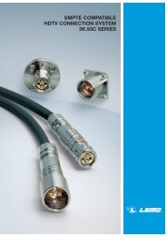
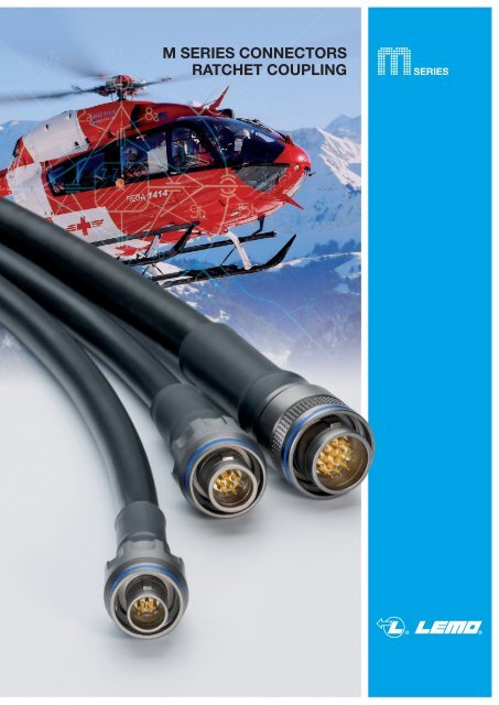
M SERIES CONNECTORS<br />
RATCHET COUPLING
Introduction<br />
www.lemo.com<br />
® ®<br />
This <strong>catalog</strong>ue gives the complete description of LEMO M <strong>series</strong> connectors. M <strong>series</strong> connectors are lightweight triplestart<br />
ratchet coupling type connectors designed for avionics, aerospace, military, security, motorsport and heavy duty applications.<br />
The LEMO manufacturing programme has been extended to almost 40 <strong>series</strong> divided into 7 product families with specific<br />
mating and environmental characteristics. Each <strong>series</strong> includes a wide variety of plug, socket and coupler models, available<br />
in contact configurations adapted to all round cables. Watertight models are also available. Since LEMO connectors<br />
are perfectly screened and designed to guarantee very low resistance to shell electrical continuity, they are particularly adapted<br />
to applications where electromagnetic compatibility (EMC) is important.<br />
Technical Characteristics<br />
Materials and Treatments<br />
Outer shell<br />
Conical nut<br />
Earthing crown<br />
Coupling nut<br />
Ratchet<br />
Hexagonal nut<br />
Component<br />
Male crimp contact<br />
Female crimp contact<br />
Clips<br />
Insulator<br />
O-ring<br />
Sealing resin<br />
Cable rear seal<br />
Spring<br />
Material (Standard)<br />
Brass (UNS C 38500)<br />
Aluminium alloy (AA 6262A or AA 6023)<br />
Brass (UNS C 38500)<br />
Aluminium alloy (AA 6262A or AA 6023)<br />
Bronze (UNS C 54400) or special brass<br />
Brass (UNS C 38500)<br />
Aluminium alloy (AA 6262A or AA 6023)<br />
Special PEEK<br />
Brass (UNS C 38500)<br />
Aluminium alloy (AA 6262A or AA 6023)<br />
Brass (UNS C 34500)<br />
Bronze (UNS C 54400)<br />
Cu-Be or special steel<br />
PEEK<br />
Silicone<br />
FPM/FKM (Viton ®)<br />
Epoxy (Araldite ® or Stycast ®)<br />
Shell<br />
material code<br />
X C<br />
Fluorosilicone<br />
Stainless steel<br />
Surface treatment (µm)<br />
chrome nickel gold Notes<br />
Cu Ni Cr Cu Ni Cu Ni Au<br />
0.5 3 0.3 – – – – –<br />
– – – – 5 – – – 1)<br />
0.5 3 0.3 – – – – –<br />
– – – – 5 – – – 1)<br />
– – – – – 0.5 – 1.5<br />
– – – 0.5 3 – – –<br />
– – – 0.5 3 – – –<br />
–<br />
– – – 0.5 3 – – –<br />
– – – – 5 – – –<br />
– – – – – 0.5 3 1.0<br />
– – – – – 0.5 3 1.5<br />
without treatment<br />
–<br />
–<br />
–<br />
–<br />
–<br />
–<br />
Notes: standards for surface treatment are as follows: chrome-plated FS QQ-C-320B; nickel-plated FS QQ-N-290A or MIL DTL 32119; gold-plated ISO 27874.<br />
1) anthracite colour.<br />
Environmental performance<br />
Characteristics Value IEC international MIL-spec tests<br />
Operating temperature (mated)<br />
Ingress protection index<br />
Fungus<br />
Flammability<br />
Fluid contamination 1)<br />
Sand and dust 2)<br />
Lightning strike<br />
Altitude-low temp 3)<br />
Salt fog 4)<br />
Thermal shock<br />
Altitude immersion<br />
Air leakage 5)<br />
Humidity<br />
- 55°C/+200°C<br />
IP 68 (at 2 m, 15Hr) IEC 60529<br />
Satisfied - by material analysis MIL-STD 810F-508.5<br />
60 sec. front and back face EIA-364-104A<br />
Fuels, gasoline, hydraulic oils, solvents, de-icing MIL-STD-810F method 504<br />
6 hr, 55°C, blowing < 150 µm dust MIL-STD 810F-510.4<br />
10 K amps - 6 times EIA-364-75<br />
-65°C; 40’000 feet and 400 VAC EIA-364-105A<br />
Alum. shell (slight pitting after 48Hr), Brass shell (500Hr) IEC 60512-6 test 11f EIA-364-26<br />
5 cycles: -65° C to +150°C IEC 60512-11-4 EIA-364-32 test condition IV<br />
No moisture on contacts EIA-364-03<br />
< 10 -7 mbar. l/sec (Helium) IEC 60512-7 14 b MIL-STD-1344 method 1008.1<br />
21 days at 95% IEC 60068-2 EIA-364-31 method IV<br />
Note:<br />
1) Connectors immersed at both 70°C and 25°C according to specification. Connectors are then inspected, no visual signs of damage seen.<br />
Fuels: Kerosene, JP4, (Nato F40) at 70°C +/- 2°C. Gasoline: ASTM 4814. Hydraulic oils: Mineral oil based MIL-H-5606.<br />
Solvents: Isopropanol. De-icing fluids: 25% ethylene glycol.<br />
2) No signs of damage, connectors opened and closed without difficulty. Dust or sand was not inside connector.<br />
3) Wired mated connectors = no voltage breakdown, shell to all contacts (connected together) w/400 VAC after 1 hour at 65° C<br />
at 40’000 feet altitude.<br />
4) Corrosion resistance. Inspection: salt deposits shall be removed by gentle wash in running water with light brushing using soft brush.<br />
Aluminium Shell (material code: X) max: 96 hours. Brass shell (material code: C) over 500 hours.<br />
5) Only for vacuumtight model (HE•)<br />
1
® ®<br />
Electrical performance<br />
Endurance<br />
Gunfire vibration<br />
Vibration-Sine 8)<br />
Vibration-Random<br />
Shock<br />
Acceleration<br />
Contact retention<br />
Torque<br />
Characteristics Value IEC international MIL-spec tests<br />
Insulation resist. (at ambient temp.) 6)<br />
Dielectric withstanding volt. (sea level)<br />
Contact resistance<br />
Current rating<br />
Shell to shell conductivity<br />
Shielding effectiveness, low frequency<br />
Shielding effectiveness, high frequency<br />
> 10 12 Ω, > 10 10 Ω (after humidity) IEC 60512-2 test 3a EIA-364-21<br />
See table page 16-17 IEC 60512-2 test 4a EIA-364-20<br />
See table below 7) IEC 60512-2 test 2a EIA-364-06<br />
See insulator configuration page 16-17 IEC 60512-3 test 5a<br />
< 1.5mΩ IEC 60512-2-6 EIA-364-83<br />
≥ 80 dB up to 1GHz EIA-364-66<br />
≥ 70 dB (3GHz), ≥ 58 dB (6GHz), ≥ 40 dB (10GHz) EIA-364-66<br />
Note: 6) After humidity test: 21 days at 95% RH according to IEC 60068-2. Insulation resistance measured between the contacts and contact/shell.<br />
Contact resistance 7)<br />
IEC 60512-2 test 2a<br />
0.5 0.7 0.9 1.3<br />
≤ 8.7 ≤ 6.1 ≤ 4.8 ≤ 3.6<br />
Mechanical performance<br />
Value<br />
ø A<br />
(mm)<br />
mΩ<br />
Notes: 7) after 5000 mating cycles and the salt spray test according to IEC 60512-6 test 11 f.<br />
Characteristics Value IEC international MIL-spec tests<br />
3000 cycles IEC 60512-5 test 9a EIA-364-09<br />
25 to 2000 Hz, 3 axis (Apache helicopter) MIL-STD-810F method 519.5<br />
30 g, 3 axis, 12 hr MIL-STD-202 method 204-G<br />
50-2000 Hz, 37.8 g rms-3 axes; 4h amb IEC 60512-6-4 EIA-364-28 test cond. V letter I<br />
300 g - 3 msec IEC 60512-6-3 EIA-364-27 condition D<br />
50 g acceleration MIL-STD-1344 - 2011-1, A<br />
> 22 N (ø 0.7mm), > 30N (ø 0.9 mm) IEC 60512-8 test 15a<br />
See table below<br />
Note: 8) Amplitude: 30G. Frequency: 10 to 2000 Hz. Time per axis: 4 hours (X, Y, Z). No signal discontinuity above 1 µs.<br />
Series<br />
0M<br />
1M<br />
2M<br />
3M<br />
Coupling torque Coupling torque<br />
tightning (N.cm) untightning (N.cm)<br />
4 5<br />
10 11<br />
20 14<br />
34 29<br />
Note: 9) Higher contact density = larger torque force.<br />
Series<br />
TM<br />
4M<br />
LM<br />
5M<br />
Coupling torque Coupling torque<br />
tightning (N.cm) untightning (N.cm)<br />
26 30<br />
26 25<br />
48 9) 43<br />
91 9) 54<br />
2 www.lemo.com
www.lemo.com<br />
® ®<br />
The M Series connector offers a new innovative design for avionics, aerospace, military, security, motorsport and heavy<br />
duty applications.<br />
Made of high-strength aluminium, this connector is one of the lightest and most compact of the LEMO product line.<br />
A one-grip ratchet screw system enables quick and secure coupling of the connectors. The arctic grip makes it easy to manipulate<br />
the connector while wearing gloves or when the connector is located in a difficult to access area.<br />
Features<br />
– Ratchet-coupling mechanism – Quick mating: less than 3/4 turn to seat<br />
– Compact design for space savings – Lightweight<br />
– Oil and fuel resistant – High vibration and shock resistance<br />
– 360° screening for full EMC shielding – Sealed to IP68 when mated<br />
– Colour coding / keying – Reverse sex configuration<br />
– Scoop proof – Pin configuration from 2 to 114 contacts<br />
– Threaded for MIL-DTL-38999L backshell<br />
Metal housing models (page 5)<br />
Straight plugs<br />
USB models<br />
FM�<br />
FM�<br />
FM�<br />
FG�<br />
FG�<br />
FG�<br />
FM�<br />
Fixed sockets<br />
EG�<br />
EG�<br />
EC�<br />
EC�<br />
ED�<br />
ED�<br />
M Series<br />
PB�<br />
PB�<br />
PB�<br />
PE�<br />
Straight plugs Fixed sockets<br />
FG� EG�<br />
EG�<br />
PV�<br />
PV�<br />
PV�<br />
PF�<br />
PF�<br />
HE�<br />
Free sockets<br />
PM�<br />
PM�<br />
PH�<br />
PH�<br />
Watertight model (unmated)<br />
Fixed socket<br />
3
® ®<br />
Part Numbering System<br />
Model: (page 5)<br />
Alignment key: (page 15)<br />
Series: (page 5)<br />
Insert configuration: (page 16)<br />
Part Number Example<br />
1<br />
2<br />
3<br />
4<br />
5<br />
6<br />
Fixed socket 5 4 6 3 2 1 1 3 2 7 5 6 4 Straight plug<br />
outer shell<br />
o-ring<br />
hexagonal nut<br />
insulator<br />
female contact<br />
earthing crown<br />
Plug<br />
Free socket<br />
FM N . 1M . 305 .<br />
X L C<br />
PM N . 1M . 305 . X L M<br />
Fixed socket HE N . 1M . 305 . X L N P<br />
Variant:<br />
T = Mold stop<br />
P=Potted<br />
M=MIL-DTL-38999L shell thread<br />
Contact: (page 18)<br />
Insulator: L = PEEK<br />
Housing: (page 17)<br />
Straight plug:<br />
FMN.1M.305.XLC = straight plug with key (N), 1M <strong>series</strong>, multipole type with 5 contacts, outer shell in anthracite nickel-plated<br />
aluminium alloy, PEEK insulator, male crimp contacts.<br />
Straight plug:<br />
FGN.1M.305.XLCM = straight plug with key (N), arctic grip, 1M <strong>series</strong>, multipole type with 5 contacts, outer shell in anthracite<br />
nickel-plated aluminium alloy, PEEK insulator, male crimp contacts and with MIL-DTL-38999L thread for additional backshell<br />
(not supplied).<br />
Fixed socket:<br />
HEN.1M.305.XLNP = fixed socket, nut fixing, with key (N), 1M <strong>series</strong>, multipole type with 5 contacts, outer shell in anthracite<br />
nickel-plated aluminium alloy, PEEK insulator, female print contacts, watertight.<br />
Part Section Showing Internal Components<br />
FG N . 1M . 305 . X L C M<br />
Free socket:<br />
PMN.1M.305.XLMT = free socket with key (N), 1M <strong>series</strong>, multipole type with 5 contacts, outer shell in anthracite nickel-plated<br />
aluminium alloy, PEEK insulator, female crimp contacts and mold stop.<br />
outer shell<br />
insulator<br />
male contact<br />
rear seal<br />
tightening screw<br />
ratchet mechanism<br />
spring<br />
4 www.lemo.com<br />
T<br />
1<br />
2<br />
3<br />
4<br />
5<br />
6<br />
7
www.lemo.com<br />
ø B<br />
ø D<br />
ø F<br />
ø B<br />
ø D<br />
e<br />
Ls/Lr<br />
X P<br />
X<br />
Ls/Lr<br />
Ls/Lr<br />
M P<br />
1.5<br />
9 P<br />
ø C<br />
ø A<br />
ø C<br />
ø A<br />
ø C<br />
ø A<br />
FM●<br />
FM●<br />
Metal housing models<br />
® ®<br />
Straight plug, key (N) or keys (P, R, S, T, U, V, W and X)<br />
with knurled grip<br />
Reference<br />
Model Series<br />
FM● 0M<br />
FM● 1M<br />
FM● 2M<br />
FM● 3M<br />
FM● TM<br />
FM● 4M<br />
FM● LM<br />
FM● 5M<br />
Straight plug, key (N) or keys (P, R, S, T, U, V, W and X)<br />
with knurled grip and MIL-DTL-38999L shell thread<br />
Reference<br />
Model Series<br />
FM● 1M<br />
FM● 2M<br />
FM● 3M<br />
FM● TM<br />
FM● 4M<br />
FM● LM<br />
FM● 5M<br />
Dimensions (mm)<br />
A B C D Ls Lr P X<br />
13.1 8.8 12.7 8.0 24.1 24.1 3.9 6.7<br />
14.6 10.5 14.2 9.7 24.1 24.1 3.9 6.7<br />
17.6 14.0 17.2 13.0 24.5 24.5 3.9 7.1<br />
19.6 16.0 19.2 15.0 24.5 24.5 3.9 7.1<br />
22.5 17.9 22.0 16.7 28.6 28.6 3.4 7.6<br />
25.0 20.7 24.5 19.5 28.6 28.6 3.4 7.6<br />
28.5 23.9 28.0 22.7 28.6 28.6 3.4 7.6<br />
34.0 29.7 33.5 28.5 28.6 28.6 3.4 7.6<br />
Part number example: FMN.1M.305.XLC<br />
Note: Ls = standard gender, Lr = reverse gender<br />
FM●<br />
Straight plug, key (N) or keys (P, R, S, T, U, V, W and X)<br />
with knurled grip and mold stop<br />
Reference<br />
Model Series<br />
FM● 0M<br />
FM● 1M<br />
FM● 2M<br />
FM● 3M<br />
FM● TM<br />
FM● 4M<br />
FM● LM<br />
FM● 5M<br />
Dimensions (mm)<br />
A B C D F Ls Lr M P X<br />
13.1 8.8 12.7 8.0 10.7 27.1 27.1 9.7 3.9 6.7<br />
14.6 10.5 14.2 9.7 12.4 27.1 27.1 9.7 3.9 6.7<br />
17.6 14.0 17.2 13.0 15.5 27.5 27.5 10.1 3.9 7.1<br />
19.6 16.0 19.2 15.0 17.5 27.5 27.5 10.1 3.9 7.1<br />
22.5 17.9 22.0 16.7 19.8 31.6 31.6 10.6 3.4 7.6<br />
25.0 20.7 24.5 19.5 22.6 31.6 31.6 10.6 3.4 7.6<br />
28.5 23.9 28.0 22.7 25.8 31.6 31.6 10.6 3.4 7.6<br />
34.0 29.7 33.5 28.5 31.4 31.6 31.6 10.6 3.4 7.6<br />
Part number example: FMN.1M.305.XLCT<br />
Note: Ls = standard gender, Lr = reverse gender<br />
Dimensions (mm)<br />
A C e Ls Lr P Code1) 14.6 14.2 M12x1.0 26.4 26.4 3.9 A<br />
17.6 17.2 M15x1.0 26.4 26.4 3.9 B<br />
19.6 19.2 M18x1.0 26.4 26.4 3.9 C<br />
22.5 22.0 M18x1.0 30.0 30.0 3.4 C<br />
25.0 24.5 M22x1.0 30.0 30.0 3.4 D<br />
28.5 28.0 M25x1.0 30.0 30.0 3.4 E<br />
34.0 33.5 M31x1.0 30.0 30.0 3.4 G<br />
Part number example: FMN.1M.305.XLCM<br />
Note: Ls = standard gender, Lr = reverse gender. 1) MIL-DTL-38999L shell size code<br />
(backshell not supplied)<br />
5
® ®<br />
ø B<br />
ø D<br />
ø F<br />
ø B<br />
ø D<br />
e<br />
9<br />
X<br />
X<br />
Ls/Lr<br />
Ls/Lr<br />
M P<br />
Ls/Lr<br />
1.5<br />
P<br />
P<br />
ø C<br />
ø A<br />
ø C<br />
ø A<br />
ø C<br />
ø A<br />
FG●<br />
FG●<br />
Straight plug, key (N) or keys (P, R, S, T, U, V, W and X)<br />
with arctic grip<br />
Reference<br />
Model Series<br />
FG● 0M<br />
FG● 1M<br />
FG● 2M<br />
FG● 3M<br />
FG● TM<br />
FG● 4M<br />
FG● LM<br />
FG● 5M<br />
Part number example: FGN.1M.305.XLC<br />
Note: Ls = standard gender, Lr = reverse gender<br />
Straight plug, key (N) or keys (P, R, S, T, U, V, W and X)<br />
with arctic grip and mold stop<br />
Reference<br />
Model Series<br />
FG● 0M<br />
FG● 1M<br />
FG● 2M<br />
FG● 3M<br />
FG● TM<br />
FG● 4M<br />
FG● LM<br />
FG● 5M<br />
Part number example: FGN.1M.305.XLCT<br />
Dimensions (mm)<br />
A B C D Ls Lr P X<br />
14.4 8.8 12.7 8.0 24.1 24.1 3.9 6.7<br />
15.9 10.5 14.2 9.7 24.1 24.1 3.9 6.7<br />
18.9 14.0 17.2 13.0 24.5 24.5 3.9 7.1<br />
20.9 16.0 19.2 15.0 24.5 24.5 3.9 7.1<br />
23.4 17.9 22.0 16.7 28.6 28.6 3.4 7.6<br />
25.9 20.7 24.5 19.5 28.6 28.6 3.4 7.6<br />
29.4 23.9 28.0 22.7 28.6 28.6 3.4 7.6<br />
34.9 29.7 33.5 28.5 28.6 28.6 3.4 7.6<br />
Dimensions (mm)<br />
A B C D F Ls Lr M P X<br />
14.4 8.8 12.7 8.0 10.7 27.1 27.1 9.7 3.9 6.7<br />
15.9 10.5 14.2 9.7 12.4 27.1 27.1 9.7 3.9 6.7<br />
18.9 14.0 17.2 13.0 15.5 27.5 27.5 10.1 3.9 7.1<br />
20.9 16.0 19.2 15.0 17.5 27.5 27.5 10.1 3.9 7.1<br />
23.4 17.9 22.0 16.7 19.8 31.6 31.6 10.6 3.4 7.6<br />
25.9 20.7 24.5 19.5 22.6 31.6 31.6 10.6 3.4 7.6<br />
29.4 23.9 28.0 22.7 25.8 31.6 31.6 10.6 3.4 7.6<br />
34.9 29.7 33.5 28.5 31.4 31.6 31.6 10.6 3.4 7.6<br />
Note: Ls = standard gender, Lr = reverse gender<br />
FG●<br />
Straight plug, key (N) or keys (P, R, S, T, U, V, W and X)<br />
with arctic grip and MIL-DTL-38999L shell thread<br />
Reference<br />
Model Series<br />
FG● 1M<br />
FG● 2M<br />
FG● 3M<br />
FG● TM<br />
FG● 4M<br />
FG● LM<br />
FG● 5M<br />
Part number example: FGN.1M.305.XLCM<br />
Dimensions (mm)<br />
A C e Ls Lr P Code 1)<br />
15.9 14.2 M12x1.0 26.4 26.4 3.9 A<br />
18.9 17.2 M15x1.0 26.4 26.4 3.9 B<br />
20.9 19.2 M18x1.0 26.4 26.4 3.9 C<br />
23.4 22.0 M18x1.0 30.0 30.0 3.4 C<br />
25.9 24.5 M22x1.0 30.0 30.0 3.4 D<br />
29.4 28.0 M25x1.0 30.0 30.0 3.4 E<br />
34.9 33.5 M31x1.0 30.0 30.0 3.4 G<br />
Note: Ls = standard gender, Lr = reverse gender. 1) MIL-DTL-38999L shell size code<br />
(backshell not supplied)<br />
6 www.lemo.com
www.lemo.com<br />
ø C<br />
e<br />
e<br />
S 2<br />
4.5<br />
5.6<br />
S 1<br />
S 3<br />
ø B<br />
E maxi<br />
S 1 S 2<br />
Ls/Lr<br />
Ls/Lr<br />
G<br />
Ls/Lr<br />
S 1<br />
D<br />
P<br />
P<br />
D<br />
E maxi<br />
P<br />
E maxi<br />
G<br />
e<br />
ø C<br />
S 2<br />
ø C<br />
ø A<br />
EG●<br />
Fixed socket, nut fixing, key (N)<br />
or keys (P, R, S, T, U, V, W and X)<br />
Reference<br />
Dimensions (mm)<br />
® ®<br />
Model Series C D e E Ls Lr P S1 S2<br />
EG● 0M 12.7 6.8 M9x0.6 5.0 18.1 18.1 5.3 8.2 11.0<br />
EG● 1M 14.2 6.8 M11x1.0 4.5 18.1 18.1 5.3 9.5 13.0<br />
EG● 2M 17.2 6.8 M14x1.0 4.5 18.1 18.1 5.3 12.5 17.0<br />
EG● 3M 19.2 6.8 M16x1.0 4.0 18.1 18.1 5.3 14.5 19.0<br />
EG● TM 22.0 9.4 M18x1.0 4.0 19.8 21.7 7.9 16.5 22.0<br />
EG● 4M 24.5 9.4 M21x1.0 4.0 19.8 21.7 7.9 19.5 25.0<br />
EG● LM 28.0 9.4 M24x1.0 4.0 19.8 21.7 7.9 22.5 30.0<br />
EG● 5M 33.5 9.4 M30x1.0 4.0 19.8 21.7 7.9 28.5 36.0<br />
Part number example: EGN.1M.305.XLM<br />
Panel cut-out (page 23).<br />
Note: Ls = standard gender, Lr = reverse gender<br />
EG●<br />
Fixed socket, nut fixing, key (N)<br />
or keys (P, R, S, T, U, V, W and X) for printed circuit<br />
Reference<br />
Dimensions (mm)<br />
Model Series C D e E G Ls Lr P S1 S2<br />
EG● 0M 12.7 6.8 M9x0.6 5.0 16.8 18.1 18.1 5.3 8.2 11.0<br />
EG● 1M 14.2 6.8 M11x1.0 4.5 16.8 18.1 18.1 5.3 9.5 13.0<br />
EG● 2M 17.2 6.8 M14x1.0 4.5 16.8 18.1 18.1 5.3 12.5 17.0<br />
EG● 3M 19.2 6.8 M16x1.0 4.0 16.8 18.1 18.1 5.3 14.5 19.0<br />
EG● TM 22.0 9.4 M18x1.0 4.0 18.9 19.8 21.7 7.9 16.5 22.0<br />
EG● 4M 24.5 9.4 M21x1.0 4.0 18.9 19.8 21.7 7.9 19.5 25.0<br />
EG● LM 28.0 9.4 M24x1.0 4.0 18.9 19.8 21.7 7.9 22.5 30.0<br />
EG● 5M 33.5 9.4 M30x1.0 4.0 18.9 19.8 21.7 7.9 28.5 36.0<br />
Part number example: EGN.1M.305.XLN<br />
Panel cut-out (page 23). PCB drilling pattern (page 24).<br />
Note: Ls = standard gender, Lr = reverse gender<br />
EC●<br />
Fixed socket with two nuts, key (N)<br />
or keys (P, R, S, T, U, V, W and X)<br />
Reference<br />
Model Series<br />
EC● 0M<br />
EC● 1M<br />
EC● 2M<br />
EC● 3M<br />
EC● TM<br />
EC● 4M<br />
EC● LM<br />
EC● 5M<br />
Part number example: ECN.1M.305.XLM<br />
Panel cut-out (page 23).<br />
Note: Ls = standard gender, Lr = reverse gender.<br />
This model is not IP68 (no panel sealing).<br />
Dimensions (mm)<br />
A B C E e G Ls Lr P S1 S2 S3<br />
17 4.72 18.2 5.0 M13x0.75 16.8 18.1 18.1 5.3 11.5 14.0 16.0<br />
18 5.95 19.2 5.0 M14x1.00 16.8 18.1 18.1 5.3 12.5 16.0 17.0<br />
21 8.95 21.5 4.0 M17x1.00 16.8 18.1 18.1 5.3 15.5 18.0 19.0<br />
23 10.95 25.0 4.0 M19x1.00 16.8 18.1 18.1 5.3 17.5 20.0 22.0<br />
27 12.30 28.0 2.5 M22x1.00 18.9 19.8 21.7 7.9 20.5 23.0 25.0<br />
29 13.95 34.0 2.5 M24x1.00 18.9 19.8 21.7 7.9 22.5 25.0 30.0<br />
33 17.95 36.0 2.5 M28x1.00 18.9 19.8 21.7 7.9 26.5 29.0 32.0<br />
38 22.90 41.0 2.5 M33x1.00 18.9 19.8 21.7 7.9 31.5 34.0 37.0<br />
7
® ®<br />
ø C<br />
N<br />
H<br />
N<br />
H<br />
5.6<br />
ø B<br />
4.5<br />
S 3<br />
ø V<br />
ø V<br />
ø A<br />
Ls/Lr<br />
S 1<br />
ø A<br />
ø B<br />
5.6<br />
ø B<br />
4.5<br />
K<br />
K<br />
P<br />
E maxi<br />
G<br />
Ls/Lr<br />
e<br />
S 2<br />
G<br />
Ls/Lr<br />
G<br />
ø A<br />
P<br />
P<br />
ø C<br />
ø C<br />
EC●<br />
ED●<br />
ED●<br />
Fixed socket with two nuts, key (N)<br />
or keys (P, R, S, T, U, V, W and X) for printed circuit<br />
Reference<br />
Model Series<br />
EC● 0M<br />
EC● 1M<br />
EC● 2M<br />
EC● 3M<br />
EC● TM<br />
EC● 4M<br />
EC● LM<br />
EC● 5M<br />
Part number example: ECN.1M.305.XLN<br />
Panel cut-out (page 23). PCB drilling pattern (page 24).<br />
Note: Ls = standard gender, Lr = reverse gender<br />
Fixed socket with square flange, key (N)<br />
or keys (P, R, S, T, U, V, W and X)<br />
Reference<br />
Model Series<br />
ED● 0M<br />
ED● 1M<br />
ED● 2M<br />
ED● 3M<br />
ED● TM<br />
ED● 4M<br />
ED● LM<br />
ED● 5M<br />
Part number example: EDN.1M.305.XLM<br />
Panel cut-out (page 23).<br />
Note: Ls = standard gender, Lr = reverse gender<br />
Fixed socket with square flange, key (N)<br />
or keys (P, R, S, T, U, V, W and X) for printed circuit<br />
Reference<br />
Model Series<br />
ED● 0M<br />
ED● 1M<br />
ED● 2M<br />
ED● 3M<br />
ED● TM<br />
ED● 4M<br />
ED● LM<br />
ED● 5M<br />
Part number example: EDN.1M.305.XLN<br />
Note: Ls = standard gender, Lr = reverse gender<br />
Dimensions (mm)<br />
A B C E e G Ls Lr P S1 S2 S3<br />
17 4.72 18.2 5.0 M13x0.75 16.8 18.1 18.1 5.3 11.5 14.0 16.0<br />
18 5.95 19.2 5.0 M14x1.00 16.8 18.1 18.1 5.3 12.5 16.0 17.0<br />
21 8.95 21.5 4.0 M17x1.00 16.8 18.1 18.1 5.3 15.5 18.0 19.0<br />
23 10.95 25.0 4.0 M19x1.00 16.8 18.1 18.1 5.3 17.5 20.0 22.0<br />
27 12.30 28.0 2.5 M22x1.00 18.9 19.8 21.7 7.9 20.5 23.0 25.0<br />
29 13.95 34.0 2.5 M24x1.00 18.9 19.8 21.7 7.9 22.5 25.0 30.0<br />
33 17.95 36.0 2.5 M28x1.00 18.9 19.8 21.7 7.9 26.5 29.0 32.0<br />
38 22.90 41.0 2.5 M33x1.00 18.9 19.8 21.7 7.9 31.5 34.0 37.0<br />
Dimensions (mm)<br />
A B C G H K Ls Lr N P V<br />
20.6 4.72 12.7 12.8 11.0 1.5 18.1 18.1 16.0 5.3 2.7<br />
23.8 5.95 14.2 12.8 12.9 1.5 18.1 18.1 18.4 5.3 3.3<br />
26.9 8.95 17.2 12.8 15.1 1.5 18.1 18.1 20.6 5.3 3.3<br />
29.0 10.95 19.2 12.8 16.6 1.5 18.1 18.1 22.1 5.3 3.3<br />
31.4 12.30 22.0 14.5 18.3 2.0 19.8 21.7 23.8 7.9 3.3<br />
34.6 13.95 24.5 14.5 20.6 2.0 19.8 21.7 26.1 7.9 3.3<br />
38.0 17.95 28.0 14.5 23.0 2.0 19.8 21.7 28.5 7.9 3.3<br />
43.7 22.90 33.5 14.5 27.0 2.0 19.8 21.7 32.5 7.9 3.3<br />
Panel cut-out (page 23). PCB drilling pattern (page 24).<br />
8 www.lemo.com
www.lemo.com<br />
ø C<br />
ø F<br />
ø B<br />
ø D<br />
N<br />
H<br />
N<br />
H<br />
ø A<br />
ø V<br />
X<br />
M<br />
1.5<br />
ø E<br />
ø F<br />
ø B<br />
ø D<br />
ø A<br />
ø 3.3<br />
ø E<br />
e<br />
L<br />
S 1<br />
X<br />
R<br />
P<br />
e<br />
E maxi S 2<br />
M<br />
1.5<br />
ø A<br />
Ss/Sr G<br />
K<br />
Ss/Sr<br />
9<br />
K<br />
G<br />
P<br />
P<br />
ø C<br />
ø C<br />
PE●<br />
® ®<br />
Fixed socket, nut fixing, key (N) or keys (P, R, S, T, U, V,<br />
W and X) with mold stop (back panel mounting)<br />
Reference<br />
Model Series<br />
PE● 0M<br />
PE● 1M<br />
PE● 2M<br />
PE● 3M<br />
PE● TM<br />
PE● 4M<br />
PE● LM<br />
PE● 5M<br />
Dimensions (mm)<br />
A B C D E e Ls Lr M P R S1 S2<br />
17 8.8 16.8 8.0 5.0 M13x0.75 25.6 25.6 9.7 5.3 13.8 11.5 14<br />
18 10.5 17.8 9.7 5.0 M14x1.00 25.6 25.6 9.7 5.3 13.8 12.5 16<br />
21 14.0 20.8 13.0 5.0 M17x1.00 26.0 26.0 10.1 5.3 13.8 15.5 18<br />
23 16.0 22.8 15.0 5.0 M19x1.00 26.0 26.0 10.1 5.3 13.8 17.5 20<br />
27 17.9 25.8 16.7 4.0 M22x1.00 29.5 30.1 10.6 7.9 16.9 20.5 23<br />
29 20.7 27.8 19.5 4.0 M24x1.00 29.5 30.1 10.6 7.9 16.9 22.5 25<br />
33 23.9 31.8 22.7 4.0 M28x1.00 29.5 30.1 10.6 7.9 16.9 26.5 29<br />
38 29.7 36.8 28.5 4.0 M33x1.00 29.5 30.1 10.6 7.9 16.9 31.5 34<br />
Part number example: PEN.1M.305.XLMT<br />
Panel cut-out (page 23).<br />
Note: this model is only available with mold stop. The dimensions «F» and «X» are<br />
the same as the PB● models. Ls = standard gender, Lr = reverse gender.<br />
PF●<br />
Fixed socket with square flange, key (N)<br />
or keys (P, R, S, T, U, V, W and X) with mold stop<br />
Reference<br />
Model Series<br />
PF● 0M<br />
PF● 1M<br />
PF● 2M<br />
PF● 3M<br />
PF● TM<br />
PF● 4M<br />
PF● LM<br />
PF● 5M<br />
Dimensions (mm)<br />
A B C D E F G H K N Ss Sr V<br />
20.6 8.8 12.7 8.0 10.7 10.7 12.8 11.0 1.5 16.0 11.3 11.3 2.7<br />
23.8 10.5 14.2 9.7 12.4 12.4 12.8 12.9 1.5 18.4 11.3 11.3 3.3<br />
26.9 14.0 17.2 13.0 15.5 15.5 12.8 15.1 1.5 20.6 11.7 11.7 3.3<br />
29.0 16.0 19.2 15.0 17.5 17.5 12.8 16.6 1.5 22.1 11.7 11.7 3.3<br />
31.4 17.9 22.0 16.7 19.8 19.8 14.5 18.3 2.0 23.8 13.0 13.6 3.3<br />
34.6 20.7 24.5 19.5 22.6 22.6 14.5 20.6 2.0 26.1 13.0 13.6 3.3<br />
38.0 23.9 28.0 22.7 25.8 25.8 14.5 23.0 2.0 28.5 13.0 13.6 3.3<br />
47.0 29.7 33.5 28.5 33.0 31.4 14.5 29.4 2.0 37.0 13.0 13.6 3.3<br />
Part number example: PFN.1M.305.XLMT<br />
Panel cut-out (page 23).<br />
Note: this model is only available with mold stop. The dimensions «M», «P» and «X»<br />
are the same as the PB● models. Ss = standard gender, Sr = reverse gender.<br />
PF●<br />
Fixed socket with square flange, key (N) or keys (P, R, S,<br />
T, U, V, W and X) with MIL-DTL-38999L shell thread<br />
Reference<br />
Model Series<br />
PF● 1M<br />
PF● 2M<br />
PF● 3M<br />
PF● TM<br />
PF● 4M<br />
PF● LM<br />
PF● 5M<br />
Part number example: PFN.1M.305.XLMM<br />
Panel cut-out (page 23).<br />
Dimensions (mm)<br />
A C e E G H K N Ss Sr Code1) 23.8 14.2 M12x1.0 12.4 12.8 12.9 1.5 18.4 12.2 12.2 A<br />
26.9 17.2 M15x1.0 15.5 12.8 15.1 1.5 20.6 12.2 12.2 B<br />
29.0 19.2 M18x1.0 17.5 12.8 16.6 1.5 22.1 12.2 12.2 C<br />
31.4 22.0 M18x1.0 19.8 14.5 18.3 2.0 23.8 11.7 13.6 C<br />
34.6 24.5 M22x1.0 22.6 14.5 20.6 2.0 26.1 11.7 13.6 D<br />
38.0 28.0 M25x1.0 25.8 14.5 23.0 2.0 28.5 11.7 13.6 E<br />
47.0 33.5 M31x1.0 33.0 14.5 29.4 2.0 37.0 11.7 13.6 G<br />
Note: Ss = standard gender, Sr = reverse gender. 1) MIL-DTL-38999L shell size code<br />
(backshell not supplied)<br />
9
® ®<br />
N<br />
N<br />
N<br />
3.3<br />
3.3<br />
3.3<br />
H<br />
H<br />
H<br />
ø C<br />
ø B<br />
ø F<br />
ø B<br />
ø D<br />
ø C<br />
e<br />
Ss/Sr<br />
2<br />
X<br />
ø D<br />
X<br />
M<br />
G<br />
P<br />
A<br />
Ss/Sr P<br />
2<br />
ø C<br />
1.5<br />
G<br />
Ss/Sr P<br />
2<br />
9<br />
G<br />
A<br />
A<br />
PB●<br />
Fixed socket with antivibration flange, key (N)<br />
or keys (P, R, S, T, U, V, W and X), 2 holes fixing<br />
Reference<br />
Model Series<br />
PB● 0M<br />
PB● 1M<br />
PB● 2M<br />
PB● 3M<br />
PB● TM<br />
PB● 4M<br />
PB● LM<br />
PB● 5M<br />
Dimensions (mm)<br />
A B C D G H N P Ss Sr X<br />
27.0 8.8 14.5 8.0 8.3 21.4 16.0 5.3 15.3 15.3 6.7<br />
29.0 10.5 16.5 9.7 8.3 23.4 18.0 5.3 15.3 15.3 6.7<br />
32.0 14.0 19.5 13.0 8.3 26.4 21.0 5.3 15.7 15.7 7.1<br />
35.0 16.0 21.5 15.0 8.3 29.0 23.0 5.3 15.7 15.7 7.1<br />
38.5 17.9 24.5 16.7 11.0 32.5 26.0 7.9 15.2 17.1 7.6<br />
41.0 20.7 27.5 19.5 11.0 35.0 29.0 7.9 15.2 17.1 7.6<br />
44.0 23.9 30.5 22.7 11.0 38.0 32.0 7.9 15.2 17.1 7.6<br />
51.0 29.7 37.5 28.5 11.0 45.0 39.0 7.9 15.2 17.1 7.6<br />
Part number example: PBN.1M.305.XLM<br />
Panel cut-out (page 23).<br />
Note: Ss = standard gender, Sr = reverse gender<br />
PB●<br />
Fixed socket with antivibration flange, key (N) or keys<br />
(P, R, S, T, U, V, W and X), 2 holes fixing with mold stop<br />
Reference<br />
Dimensions (mm)<br />
Model Series A B C D F G H M N P Ss Sr X<br />
PB● 0M 27.0 8.8 14.5 8.0 10.7 8.3 21.4 9.7 16 5.3 18.3 18.3 6.7<br />
PB● 1M 29.0 10.5 16.5 9.7 12.4 8.3 23.4 9.7 18 5.3 18.3 18.3 6.7<br />
PB● 2M 32.0 14.0 19.5 13.0 15.5 8.3 26.4 10.1 21 5.3 18.7 18.7 7.1<br />
PB● 3M 35.0 16.0 21.5 15.0 17.5 8.3 29.0 10.1 23 5.3 18.7 18.7 7.1<br />
PB● TM 38.5 17.9 24.5 16.7 19.8 11.0 32.5 10.6 26 7.9 18.2 18.2 7.6<br />
PB● 4M 41.0 20.7 27.5 19.5 22.6 11.0 35.0 10.6 29 7.9 18.2 18.2 7.6<br />
PB● LM 44.0 23.9 30.5 22.7 25.8 11.0 38.0 10.6 32 7.9 18.2 18.2 7.6<br />
PB● 5M 51.0 29.7 37.5 28.5 31.4 11.0 45.0 10.6 39 7.9 18.2 18.2 7.6<br />
Part number example: PBN.1M.305.XLMT<br />
Panel cut-out (page 23).<br />
Note: Ss = standard gender, Sr = reverse gender<br />
PB●<br />
Fixed socket with antivibration flange, key (N)<br />
or keys (P, R, S, T, U, V, W and X), 2 holes fixing<br />
with MIL-DTL-38999L shell thread<br />
Reference<br />
Dimensions (mm)<br />
Model Series A C e G H N P Ss Sr Code1) PB● 1M 29.0 16.5 M12x1.0 8.3 23.4 18.0 5.3 17.2 17.2 A<br />
PB● 2M 32.0 19.5 M15x1.0 8.3 26.4 21.0 5.3 17.2 17.2 B<br />
PB● 3M 35.0 21.5 M18x1.0 8.3 29.0 23.0 5.3 17.2 17.2 C<br />
PB● TM 38.5 24.5 M18x1.0 11.0 32.5 26.0 7.9 16.2 17.1 C<br />
PB● 4M 41.0 27.5 M22x1.0 11.0 35.0 29.0 7.9 16.2 17.1 D<br />
PB● LM 44.0 30.5 M25x1.0 11.0 38.0 32.0 7.9 16.2 17.1 E<br />
PB● 5M 51.0 37.5 M31x1.0 11.0 45.0 39.0 7.9 16.2 17.1 G<br />
Part number example: PBN.1M.305.XLMM<br />
Note: Ss = standard gender, Sr = reverse gender. 1) Panel cut-out (page 23).<br />
MIL-DTL-38999L shell size code<br />
(backshell not supplied)<br />
10 www.lemo.com
N<br />
H<br />
N<br />
H<br />
N<br />
H<br />
www.lemo.com<br />
ø V<br />
ø V<br />
ø A<br />
ø C<br />
ø V<br />
ø A<br />
ø C<br />
ø B<br />
ø D<br />
ø F<br />
ø B<br />
ø D<br />
ø A<br />
ø C<br />
e<br />
X<br />
X<br />
Ss/Sr P<br />
2<br />
M<br />
G<br />
Ss/Sr P<br />
2<br />
1.5<br />
G<br />
Ss/Sr P<br />
2<br />
9<br />
G<br />
ø C<br />
ø C<br />
ø C<br />
PV●<br />
® ®<br />
Fixed socket with antivibration square flange, key (N)<br />
or keys (P, R, S, T, U, V, W and X)<br />
Reference<br />
Model Series<br />
PV● 0M<br />
PV● 1M<br />
PV● 2M<br />
PV● 3M<br />
PV● TM<br />
PV● 4M<br />
PV● LM<br />
PV● 5M<br />
Part number example: PVN.1M.305.XLM<br />
Panel cut-out (page 23).<br />
Dimensions (mm)<br />
A B C D G H N P Ss Sr V X<br />
26.9 8.8 14.5 8.0 8.3 15.1 20.6 5.3 15.3 15.3 2.7 6.7<br />
31.4 10.5 16.5 9.7 8.3 18.3 23.8 5.3 15.3 15.3 3.3 6.7<br />
34.6 14.0 19.5 13.0 8.3 20.6 26.1 5.3 15.7 15.7 3.3 7.1<br />
38.0 16.0 21.5 15.0 8.3 23.0 28.5 5.3 15.7 15.7 3.3 7.1<br />
40.3 17.9 24.5 16.7 11.0 24.6 30.1 7.9 15.2 17.1 3.3 7.6<br />
43.7 20.7 27.5 19.5 11.0 27.0 32.5 7.9 15.2 17.1 3.3 7.6<br />
47.1 23.9 30.5 22.7 11.0 29.4 34.9 7.9 15.2 17.1 3.3 7.6<br />
54.9 29.7 37.5 28.5 11.0 34.9 40.4 7.9 15.2 17.1 3.3 7.6<br />
Note: Ss = standard gender, Sr = reverse gender<br />
PV●<br />
Fixed socket with antivibration square flange, key (N)<br />
or keys (P, R, S, T, U, V, W and X) with mold stop<br />
Reference<br />
Dimensions (mm)<br />
Model Series A B C D F G H M N P Ss Sr X<br />
PV● 0M 26.9 8.8 14.5 8.0 10.7 8.3 15.1 9.7 20.6 5.3 18.3 18.3 6.7<br />
PV● 1M 31.4 10.5 16.5 9.7 12.4 8.3 18.3 9.7 23.8 5.3 18.3 18.3 6.7<br />
PV● 2M 34.6 14.0 19.5 13.0 15.5 8.3 20.6 10.1 26.1 5.3 18.7 18.7 7.1<br />
PV● 3M 38.0 16.0 21.5 15.0 17.5 8.3 23.0 10.1 28.5 5.3 18.7 18.7 7.1<br />
PV● TM 40.3 17.9 24.5 16.7 19.8 11.0 24.6 10.6 30.1 7.9 18.2 18.2 7.6<br />
PV● 4M 43.7 20.7 27.5 19.5 22.6 11.0 27.0 10.6 32.5 7.9 18.2 18.2 7.6<br />
PV● LM 47.1 23.9 30.5 22.7 25.8 11.0 29.4 10.6 34.9 7.9 18.2 18.2 7.6<br />
PV● 5M 54.9 29.7 37.5 28.5 31.4 11.0 34.9 10.6 40.4 7.9 18.2 18.2 7.6<br />
Part number example: PVN.1M.305.XLMT<br />
Panel cut-out (page 23).<br />
Note: Ss = standard gender, Sr = reverse gender.<br />
The dimension «V» is the same as the PV● models without mold stop.<br />
PV●<br />
Fixed socket with antivibration square flange, key (N)<br />
or keys (P, R, S, T, U, V, W and X)<br />
with MIL-DTL-38999L shell thread<br />
Reference<br />
Model Series<br />
PV● 1M<br />
PV● 2M<br />
PV● 3M<br />
PV● TM<br />
PV● 4M<br />
PV● LM<br />
PV● 5M<br />
Dimensions (mm)<br />
A C e G H N P Ss Sr V Code 1)<br />
31.4 16.5 M12x1.0 8.3 18.3 23.8 5.3 17.2 17.2 3.3 A<br />
34.6 19.5 M15x1.0 8.3 20.6 26.1 5.3 17.2 17.2 3.3 B<br />
38.0 21.5 M18x1.0 8.3 23.0 28.5 5.3 17.2 17.2 3.3 C<br />
40.3 24.5 M18x1.0 11.0 24.6 30.1 7.9 16.2 17.1 3.3 C<br />
43.7 27.5 M22x1.0 11.0 27.0 32.5 7.9 16.2 17.1 3.3 D<br />
47.1 30.5 M25x1.0 11.0 29.4 34.9 7.9 16.2 17.1 3.3 E<br />
54.9 37.5 M31x1.0 11.0 34.9 40.4 7.9 16.2 17.1 3.3 G<br />
Part number example: PVN.1M.305.XLMM<br />
Panel cut-out (page 23).<br />
Note: Ss = standard gender, Sr = reverse gender. 1) MIL-DTL-38999L shell size code<br />
(backshell not supplied)<br />
11
® ®<br />
ø B<br />
ø D<br />
ø F<br />
ø B<br />
ø D<br />
ø B<br />
ø D<br />
X<br />
Ls/Lr<br />
X P<br />
Ls/Lr<br />
M P<br />
1.5<br />
Ls/Lr<br />
X P<br />
ø C<br />
ø A<br />
ø C<br />
ø A<br />
ø C<br />
ø A<br />
PM●<br />
PM●<br />
PH●<br />
Free socket, key (N) or keys (P, R, S, T, U, V, W and X)<br />
with knurled grip<br />
Reference<br />
Model Series<br />
PM● 0M<br />
PM● 1M<br />
PM● 2M<br />
PM● 3M<br />
PM● TM<br />
PM● 4M<br />
PM● LM<br />
PM● 5M<br />
Part number example: PMN.1M.305.XLM<br />
Note: Ls = standard gender, Lr = reverse gender<br />
Free socket, key (N) or keys (P, R, S, T, U, V, W and X)<br />
with knurled grip and mold stop<br />
Reference<br />
Model Series<br />
PM● 0M<br />
PM● 1M<br />
PM● 2M<br />
PM● 3M<br />
PM● TM<br />
PM● 4M<br />
PM● LM<br />
PM● 5M<br />
Part number example: PMN.1M.305.XLMT<br />
Free socket, key (N) or keys (P, R, S, T, U, V, W and X)<br />
with arctic grip<br />
Reference<br />
Dimensions (mm)<br />
A B C D Ls Lr P X<br />
13.1 8.8 12.7 8.0 25.6 25.6 5.3 6.7<br />
14.6 10.5 14.2 9.7 25.6 25.6 5.3 6.7<br />
17.6 14.0 17.2 13.0 26.0 26.0 5.3 7.1<br />
19.6 16.0 19.2 15.0 26.0 26.0 5.3 7.1<br />
22.5 17.9 22.0 16.7 28.2 30.1 7.9 7.6<br />
25.0 20.7 24.5 19.5 28.2 30.1 7.9 7.6<br />
28.5 23.9 28.0 22.7 28.2 30.1 7.9 7.6<br />
34.0 29.7 33.5 28.5 28.2 30.1 7.9 7.6<br />
Dimensions (mm)<br />
A B C D F Ls Lr M P X<br />
13.1 8.8 12.7 8.0 10.7 28.6 28.6 9.7 5.3 6.7<br />
14.6 10.5 14.2 9.7 12.4 28.6 28.6 9.7 5.3 6.7<br />
17.6 14.0 17.2 13.0 15.5 29.0 29.0 10.1 5.3 7.1<br />
19.6 16.0 19.2 15.0 17.5 29.0 29.0 10.1 5.3 7.1<br />
22.5 17.9 22.0 16.7 19.8 31.2 31.2 10.6 7.9 7.6<br />
25.0 20.7 24.5 19.5 22.6 31.2 31.2 10.6 7.9 7.6<br />
28.5 23.9 28.0 22.7 25.8 31.2 31.2 10.6 7.9 7.6<br />
34.0 29.7 33.5 28.5 31.4 31.2 31.2 10.6 7.9 7.6<br />
Note: Ls = standard gender, Lr = reverse gender<br />
Dimensions (mm)<br />
Model Series A B C D Ls Lr P X<br />
PH● 0M 14.4 8.8 12.7 8.0 25.6 25.6 5.3 6.7<br />
PH● 1M 15.9 10.5 14.2 9.7 25.6 25.6 5.3 6.7<br />
PH● 2M 18.9 14.0 17.2 13.0 26.0 26.0 5.3 7.1<br />
PH● 3M 20.9 16.0 19.2 15.0 26.0 26.0 5.3 7.1<br />
PH● TM 23.4 17.9 22.0 16.7 28.2 30.1 7.9 7.6<br />
PH● 4M 25.9 20.7 24.5 19.5 28.2 30.1 7.9 7.6<br />
PH● LM 29.4 23.9 28.0 22.7 28.2 30.1 7.9 7.6<br />
PH● 5M 34.9 29.7 33.5 28.5 28.2 30.1 7.9 7.6<br />
Part number example: PHN.1M.305.XLM<br />
Note: Ls = standard gender, Lr = reverse gender<br />
12 www.lemo.com
www.lemo.com<br />
ø F<br />
ø B<br />
ø D<br />
ø C<br />
S 1<br />
H<br />
X<br />
M<br />
Ls/Lr<br />
1.5<br />
Ls/Lr<br />
3<br />
P<br />
E maxi<br />
N<br />
R<br />
P<br />
e<br />
S 2<br />
ø C<br />
ø A<br />
ø A<br />
PH●<br />
® ®<br />
Free socket, key (N) or keys (P, R, S, T, U, V, W and X)<br />
with arctic grip and mold stop<br />
Reference<br />
Model Series<br />
PH● 0M<br />
PH● 1M<br />
PH● 2M<br />
PH● 3M<br />
PH● TM<br />
PH● 4M<br />
PH● LM<br />
PH● 5M<br />
Dimensions (mm)<br />
A B C D F Ls Lr M P X<br />
14.4 8.8 12.7 8.0 10.7 28.6 28.6 9.7 5.3 6.7<br />
15.9 10.5 14.2 9.7 12.4 28.6 28.6 9.7 5.3 6.7<br />
18.9 14.0 17.2 13.0 15.5 29.0 29.0 10.1 5.3 7.1<br />
20.9 16.0 19.2 15.0 17.5 29.0 29.0 10.1 5.3 7.1<br />
23.4 17.9 22.0 16.7 19.8 31.2 31.2 10.6 7.9 7.6<br />
25.9 20.7 24.5 19.5 22.6 31.2 31.2 10.6 7.9 7.6<br />
29.4 23.9 28.0 22.7 25.8 31.2 31.2 10.6 7.9 7.6<br />
34.9 29.7 33.5 28.5 31.4 31.2 31.2 10.6 7.9 7.6<br />
Part number example: PHN.1M.305.XLMT<br />
Note: Ls = standard gender, Lr = reverse gender<br />
HE●<br />
Fixed socket, nut fixing, key (N) or keys (P, R, S, T, U, V, W<br />
and X) for printed circuit, watertight (back panel mounting)<br />
Reference<br />
Model Series<br />
HE● 0M<br />
HE● 1M<br />
HE● 2M<br />
HE● 3M<br />
HE● TM<br />
HE● 4M<br />
HE● LM<br />
HE● 5M<br />
Watertight model (unmated)<br />
Dimensions (mm)<br />
A C e E H Ls Lr N P R S1 S2<br />
17 16.8 M13x0.75 5.0 5.08 20.8 21.0 16.8 5.3 13.8 11.5 14<br />
18 17.8 M14x1.00 5.0 7.62 20.8 21.0 16.8 5.3 13.8 12.5 16<br />
21 20.8 M17x1.00 5.0 8.89 20.8 21.0 16.8 5.3 13.8 15.5 18<br />
23 22.8 M19x1.00 5.0 10.16 20.8 21.0 16.8 5.3 13.8 17.5 20<br />
27 25.8 M22x1.00 4.0 12.70 24.6 24.6 19.9 7.9 16.9 20.5 23<br />
29 27.8 M24x1.00 4.0 13.97 24.6 24.6 19.9 7.9 16.9 22.5 25<br />
33 31.8 M28x1.00 4.0 16.51 24.6 24.6 19.9 7.9 16.9 26.5 29<br />
38 36.8 M33x1.00 4.0 20.32 24.6 24.6 19.9 7.9 16.9 31.5 34<br />
Part number example: HEN.1M.305.XLNP<br />
Panel cut-out (page 23). PCB drilling pattern (page 24).<br />
Note: Ls = standard gender, Lr = reverse gender<br />
13
® ®<br />
ø 25.8<br />
ø 23.9<br />
ø 22.7<br />
ø 25.8<br />
ø 23.9<br />
ø 22.7<br />
M 24 x 1<br />
S 30<br />
31.6<br />
10.6 3.4<br />
7.6<br />
S 22.5<br />
40.5<br />
4 maxi<br />
31.6<br />
10.6 3.4<br />
7.6<br />
1.5<br />
1.5<br />
31<br />
7.9<br />
9.4<br />
ø 28<br />
ø 28.5<br />
ø 28<br />
ø 29.4<br />
ø 28<br />
FM●<br />
FG●<br />
Part number<br />
FM•.LM.U2A.XPAT<br />
Straight plug, key (W) or key (R)<br />
with arctic grip and mold stop<br />
Part number<br />
FG•.LM.U2A.XPAT<br />
EG●<br />
Straight plug, key (W) or key (R)<br />
with knurled grip and mold stop<br />
Fixed socket, female to female, nut fixing,<br />
key (W) or key (R)<br />
Part number<br />
EG•.LM.U2A.XPP<br />
USB models<br />
14 www.lemo.com
Alignment Key and Polarized Keying System<br />
www.lemo.com<br />
●●N<br />
●●P<br />
●●U<br />
●●S<br />
●●T<br />
Angles<br />
β γ<br />
165° 30°<br />
150° 60°<br />
130° 100°<br />
155° 50°<br />
135° 90°<br />
Contact type<br />
® ®<br />
M <strong>series</strong> connector model part numbers are composed of three letters. The LAST LETTER indicates the keys corresponding<br />
to a particular contact type.<br />
For example, straight plugs with N, P, R, U or W keys, are fitted with male contacts; whereas with S, T, V or X keys, plugs<br />
are fitted with female contacts. Sockets with N, P, R, U or W keys, are fitted with female contacts; whereas with S, T, V or<br />
X keys, sockets are fitted with male contacts.<br />
0M to 3M<br />
TM to 5M<br />
γ<br />
α<br />
γ<br />
S 30<br />
S 22.5<br />
M 24 x 1<br />
4 maxi<br />
β<br />
β<br />
δ<br />
18.9<br />
Front view of a socket<br />
Front view of a socket<br />
7.9<br />
9.4<br />
ø 28<br />
Model Model<br />
●●W<br />
●●R<br />
●●X<br />
●● V<br />
Nb<br />
of keys<br />
3<br />
Nb<br />
of keys<br />
5<br />
EG●<br />
Fixed socket, nut fixing, key (W) or key (R)<br />
Part number<br />
EG•.LM.U2A.XPL<br />
Alignment Key<br />
Angles<br />
α β γ δ<br />
95° 115° 35° 25°<br />
105° 115° 30° 20°<br />
100° 125° 40° 20°<br />
110° 120° 35° 25°<br />
Colour<br />
code<br />
blue<br />
yellow<br />
green<br />
red<br />
orange<br />
Colour<br />
code<br />
blue<br />
yellow<br />
red<br />
orange<br />
Plug Socket<br />
male female<br />
female male<br />
Contact type<br />
Plug Socket<br />
male female<br />
female male<br />
15
® ®<br />
Multipole<br />
0M<br />
1M<br />
2M<br />
3M<br />
TM<br />
1 4<br />
2 3<br />
Male crimp contacts<br />
for plug<br />
ø A<br />
Note: 1) Test voltage according to IEC 60512-2 test 4a. 2) For EG•, EC•, ED•, HE• socket.<br />
4<br />
3<br />
1<br />
2<br />
16 www.lemo.com<br />
Reference<br />
contacts of<br />
Female crimp contacts<br />
for sockets Number<br />
Insert configuration<br />
302<br />
303<br />
304<br />
305<br />
305<br />
307<br />
308<br />
308<br />
310<br />
312<br />
319<br />
322<br />
330<br />
325<br />
340<br />
ø A (mm)<br />
Crimp<br />
Contact<br />
type<br />
Print (straight) 2)<br />
AWG<br />
Test voltage (kV rms) 1)<br />
Contact-contact<br />
Test voltage (kV rms) 1)<br />
Contact-shell<br />
Rated current (A) 1)<br />
2 0.9 ● ● 20-22-24 1.45 1.00 10.0<br />
3 0.9 ● ● 20-22-24 1.70 1.40 8.0<br />
4 0.7 ● ● 22-24-26 1.35 0.90 7.0<br />
5 0.7 ● ● 22-24-26 1.25 1.00 6.5<br />
5 0.9 ● ● 20-22-24 1.30 1.30 9.0<br />
7 0.7 ● ● 22-24-26 1.45 1.20 7.0<br />
8 0.7 ● ● 22-24-26 1.30 1.10 5.0<br />
8 0.9 ● ● 20-22-24 1.95 1.10 10.0<br />
10 0.9 ● ● 20-22-24 1.80 1.20 8.0<br />
12 0.7 ● ● 22-24-26 1.65 1.15 7.0<br />
19 0.7 ● ● 22-24-26 1.20 1.00 4.0<br />
22 0.7 ● ● 22-24-26 tbd tbd tbd<br />
30 0.7 ● ● 22-24-26 1.10 1.00 3.5<br />
25 0.9 ● ● 20-22-24 1.10 1.25 5.0<br />
40 0.7 ● ● 22-24-26 1.05 1.20 3.0
Multipole<br />
4M<br />
LM<br />
5M<br />
Ref.<br />
C<br />
X<br />
www.lemo.com<br />
Material<br />
1 4<br />
2 3<br />
Male crimp contacts<br />
for plug<br />
Note: 1) Test voltage according to IEC 60512-2 test 4a. 2) For EG•, EC•, ED•, HE• socket. 3) Front view.<br />
Outer shell<br />
ø A<br />
Surface<br />
treatment<br />
Brass Chrome<br />
Aluminium alloy Nickel 1)<br />
Note: 1) anthracite colour.<br />
Reference<br />
contacts of<br />
Female crimp contacts<br />
for sockets Number<br />
3) 3)<br />
4<br />
3<br />
1<br />
2<br />
340<br />
348<br />
355<br />
368<br />
U2A<br />
366<br />
114<br />
ø A (mm)<br />
Housings<br />
Crimp<br />
Contact<br />
type<br />
Print (straight) 2)<br />
AWG<br />
Test voltage (kV rms) 1)<br />
Contact-contact<br />
® ®<br />
Test voltage (kV rms) 1)<br />
Contact-shell<br />
Rated current (A) 1)<br />
40 0.7 ● ● 22-24-26 1.20 1.35 3.5<br />
48 0.7 ● ● 22-24-26 1.10 1.35 3.0<br />
55 0.9 ● ● 20-22-24 tbd tbd tbd<br />
68 0.7 ● ● 22-24-26 1.40 1.65 2.5<br />
4 – Solder – 1.20 0.95 n.a.<br />
66 0.9 ● ● 20-22-24 1.60 1.70 3.0<br />
114 0.7 ● ● 22-24-26 1.37 1.34 2.0<br />
17
® ®<br />
Crimp contacts for plugs, free or fixed sockets<br />
There are 2 forms of crimp barrels:<br />
– per fig. 1, the standard design<br />
– per fig. 2, with reduced crimp barrel for small conductors.<br />
Fig. 1<br />
Ref.<br />
C<br />
B<br />
D<br />
ø A<br />
ø A<br />
Contact type<br />
Male crimp (fig. 1)<br />
Male crimp (fig. 2)<br />
Male straight print<br />
Dimension of crimp barrels<br />
0M<br />
1M<br />
2M<br />
3M<br />
TM<br />
4M<br />
LM<br />
5M<br />
Type<br />
302-303<br />
304-305<br />
305<br />
307-308<br />
308-310<br />
312-319<br />
322-330<br />
325<br />
340<br />
340-348<br />
355<br />
368<br />
366<br />
114<br />
Ref.<br />
M<br />
P<br />
N<br />
ø A<br />
Contact<br />
ø C Form<br />
(mm) (mm) per fig.<br />
0.9 1.10 1<br />
0.9 0.87 2<br />
0.7 0.87 1<br />
0.7 0.44 2<br />
0.9 1.10 1<br />
0.9 0.87 2<br />
0.7 0.87 1<br />
0.7 0.44 2<br />
0.9 1.10 1<br />
0.9 0.87 2<br />
0.7 0.87 1<br />
0.7 0.44 2<br />
0.7 0.87 1<br />
0.7 0.44 2<br />
0.9 1.10 1<br />
0.9 0.87 2<br />
0.7 0.87 1<br />
0.7 0.44 2<br />
0.7 0.87 1<br />
0.7 0.44 2<br />
0.9 1.10 1<br />
0.9 0.87 2<br />
0.7 0.87 1<br />
0.7 0.44 2<br />
0.9 1.10 1<br />
0.9 0.87 2<br />
0.7 0.87 1<br />
0.7 0.44 2<br />
ø C<br />
ø C<br />
Contact type<br />
Female crimp (fig. 1)<br />
Female crimp (fig. 2)<br />
Female straight print<br />
Ref. contact type<br />
Male Female<br />
C M<br />
B P<br />
C M<br />
B P<br />
C M<br />
B P<br />
C M<br />
B P<br />
C M<br />
B P<br />
C M<br />
B P<br />
C M<br />
B P<br />
C M<br />
B P<br />
C M<br />
B P<br />
C M<br />
B P<br />
C M<br />
B P<br />
C M<br />
B P<br />
C M<br />
B P<br />
C M<br />
B P<br />
Contacts<br />
ø A ø C<br />
ø A ø C<br />
18 www.lemo.com<br />
Fig. 2<br />
AWG<br />
Conductor<br />
Section (mm2) min. max. min. max.<br />
24 20 0.204 0.616<br />
26 22 0.128 0.382<br />
26 22 0.128 0.382<br />
32 28 0.032 0.092<br />
24 20 0.204 0.616<br />
26 22 0.128 0.382<br />
26 22 0.128 0.382<br />
32 28 0.032 0.092<br />
24 20 0.204 0.616<br />
26 22 0.128 0.382<br />
26 22 0.128 0.382<br />
32 28 0.032 0.092<br />
26 22 0.128 0.382<br />
32 28 0.032 0.092<br />
24 20 0.204 0.616<br />
26 22 0.128 0.382<br />
26 22 0.128 0.382<br />
32 28 0.032 0.092<br />
26 22 0.128 0.382<br />
32 28 0.032 0.092<br />
24 20 0.204 0.616<br />
26 22 0.128 0.382<br />
26 22 0.128 0.382<br />
32 28 0.032 0.092<br />
24 20 0.204 0.616<br />
26 22 0.128 0.382<br />
26 22 0.128 0.382<br />
32 28 0.032 0.092<br />
Part number<br />
For male contacts For female contacts<br />
FGN.0M.560.ZZC EGN.0M.660.ZZM<br />
FGN.0M.561.ZZC EGN.0M.661.ZZM<br />
FGN.0M.555.ZZC EGN.0M.655.ZZM<br />
FGN.0M.556.ZZC EGN.0M.656.ZZM<br />
FGN.0M.560.ZZC EGN.0M.660.ZZM<br />
FGN.0M.561.ZZC EGN.0M.661.ZZM<br />
FGN.0M.555.ZZC EGN.0M.655.ZZM<br />
FGN.0M.556.ZZC EGN.0M.656.ZZM<br />
FGN.0M.560.ZZC EGN.0M.660.ZZM<br />
FGN.0M.561.ZZC EGN.0M.661.ZZM<br />
FGN.0M.555.ZZC EGN.0M.655.ZZM<br />
FGN.0M.556.ZZC EGN.0M.656.ZZM<br />
FGN.0M.555.ZZC EGN.0M.655.ZZM<br />
FGN.0M.556.ZZC EGN.0M.656.ZZM<br />
FGN.0M.560.ZZC EGW.TM.660.ZZM<br />
FGN.0M.561.ZZC EGW.TM.661.ZZM<br />
FGN.0M.555.ZZC EGW.TM.655.ZZM<br />
FGN.0M.556.ZZC EGW.TM.656.ZZM<br />
FGN.0M.555.ZZC EGW.TM.655.ZZM<br />
FGN.0M.556.ZZC EGW.TM.656.ZZM<br />
FGN.0M.560.ZZC EGW.TM.660.ZZM<br />
FGN.0M.561.ZZC EGW.TM.661.ZZM<br />
FGN.0M.555.ZZC EGW.TM.655.ZZM<br />
FGN.0M.556.ZZC EGW.TM.656.ZZM<br />
FGN.0M.560.ZZC EGW.TM.660.ZZM<br />
FGN.0M.561.ZZC EGW.TM.661.ZZM<br />
FGN.0M.555.ZZC EGW.TM.655.ZZM<br />
FGN.0M.556.ZZC EGW.TM.656.ZZM<br />
Note: In order to satisfy crimp pull-test requirements to the IEC 60352-2 standard, the use of single strand cables should be avoided.
www.lemo.com<br />
N<br />
N<br />
N<br />
X<br />
sliding loop<br />
X<br />
sliding loop<br />
L<br />
L<br />
L<br />
P<br />
P<br />
X P<br />
ø 3.5<br />
Accessories<br />
ø C<br />
ø C<br />
ø C<br />
ø A<br />
ø A<br />
ø A<br />
BMF<br />
Blanking caps for plugs<br />
Part number<br />
BMF.0M.100.•AV<br />
BMF.1M.100.•AV<br />
BMF.2M.100.•AV<br />
BMF.3M.100.•AV<br />
BMF.TM.100.•AV<br />
BMF.4M.100.•AV<br />
BMF.LM.100.•AV<br />
BMF.5M.100.•AV<br />
Dimensions (mm)<br />
A C L N P X<br />
13.1 12.7 24.6 85.0 5.3 6.0<br />
14.6 14.2 24.6 85.0 5.3 6.0<br />
17.6 17.2 24.6 85.0 5.3 6.0<br />
19.6 19.2 24.6 120.0 5.3 6.0<br />
22.5 22.0 31.1 120.0 7.9 10.0<br />
25.0 24.5 31.1 120.0 7.9 10.0<br />
28.5 28.0 31.1 150.0 7.9 10.0<br />
34.0 33.5 31.1 150.0 7.9 10.0<br />
® ®<br />
Note: this cap is suitable for use with any alignment key configuration.<br />
The position «•» of the part number indicates the housing material.<br />
See page 17.<br />
BGF<br />
Blanking caps for plugs<br />
Part number<br />
BGF.0M.100.•AV<br />
BGF.1M.100.•AV<br />
BGF.2M.100.•AV<br />
BGF.3M.100.•AV<br />
BGF.TM.100.•AV<br />
BGF.4M.100.•AV<br />
BGF.LM.100.•AV<br />
BGF.5M.100.•AV<br />
Dimensions (mm)<br />
A C L N P X<br />
14.4 12.7 24.6 85.0 5.3 6.0<br />
15.9 14.2 24.6 85.0 5.3 6.0<br />
18.9 17.2 24.6 85.0 5.3 6.0<br />
20.9 19.2 24.6 120.0 5.3 6.0<br />
23.4 22.0 31.1 120.0 7.9 10.0<br />
25.9 24.5 31.1 120.0 7.9 10.0<br />
29.4 28.0 31.1 150.0 7.9 10.0<br />
34.9 33.5 31.1 150.0 7.9 10.0<br />
Note: this cap is suitable for use with any alignment key configuration.<br />
The position «•» of the part number indicates the housing material.<br />
See page 17.<br />
BME<br />
Blanking caps for fixed sockets<br />
Part number<br />
BME.0M.200.•AZ<br />
BME.1M.200.•AZ<br />
BME.2M.200.•AZ<br />
BME.3M.200.•AZ<br />
BME.TM.200.•AZ<br />
BME.4M.200.•AZ<br />
BME.LM.200.•AZ<br />
BME.5M.200.•AZ<br />
Dimensions (mm)<br />
A C L N P X<br />
13.1 12.7 23.4 85.0 3.9 6.0<br />
14.6 14.2 23.4 85.0 3.9 6.0<br />
17.6 17.2 23.4 85.0 3.9 6.0<br />
19.6 19.2 23.4 120.0 3.9 6.0<br />
22.5 22.0 31.0 120.0 3.4 10.0<br />
25.0 24.5 31.0 120.0 3.4 10.0<br />
28.5 28.0 31.0 150.0 3.4 10.0<br />
34.0 33.5 31.0 150.0 3.4 10.0<br />
Note: this cap is suitable for use with any alignment key configuration.<br />
The position «•» of the part number indicates the housing material.<br />
See page 17.<br />
19
® ®<br />
N<br />
N<br />
N<br />
X<br />
sliding loop<br />
X<br />
sliding loop<br />
L<br />
X P<br />
ø 3.5<br />
L<br />
L<br />
P<br />
P<br />
ø C<br />
ø C<br />
ø C<br />
ø A<br />
ø A<br />
ø A<br />
Blanking caps for free sockets<br />
20 www.lemo.com<br />
BMF<br />
BGE<br />
BGF<br />
Blanking caps for free sockets<br />
Part number<br />
BMF.0M.200.•AZ<br />
BMF.1M.200.•AZ<br />
BMF.2M.200.•AZ<br />
BMF.3M.200.•AZ<br />
BMF.TM.200.•AZ<br />
BMF.4M.200.•AZ<br />
BMF.LM.200.•AZ<br />
BMF.5M.200.•AZ<br />
Blanking caps for fixed sockets<br />
Part number<br />
BGE.0M.200.•AZ<br />
BGE.1M.200.•AZ<br />
BGE.2M.200.•AZ<br />
BGE.3M.200.•AZ<br />
BGE.TM.200.•AZ<br />
BGE.4M.200.•AZ<br />
BGE.LM.200.•AZ<br />
BGE.5M.200.•AZ<br />
Part number<br />
BGF.0M.200.•AZ<br />
BGF.1M.200.•AZ<br />
BGF.2M.200.•AZ<br />
BGF.3M.200.•AZ<br />
BGF.TM.200.•AZ<br />
BGF.4M.200.•AZ<br />
BGF.LM.200.•AZ<br />
BGF.5M.200.•AZ<br />
Dimensions (mm)<br />
A C L N P X<br />
13.1 12.7 23.4 85.0 3.9 6.0<br />
14.6 14.2 23.4 85.0 3.9 6.0<br />
17.6 17.2 23.4 85.0 3.9 6.0<br />
19.6 19.2 23.4 120.0 3.9 6.0<br />
22.5 22.0 31.0 120.0 3.4 10.0<br />
25.0 24.5 31.0 120.0 3.4 10.0<br />
28.5 28.0 31.0 150.0 3.4 10.0<br />
34.0 33.5 31.0 150.0 3.4 10.0<br />
Note: this cap is suitable for use with any alignment key configuration.<br />
The position «•» of the part number indicates the housing material.<br />
See page 17.<br />
Dimensions (mm)<br />
A C L N P X<br />
14.4 12.7 23.4 85.0 3.9 6.0<br />
15.9 14.2 23.4 85.0 3.9 6.0<br />
18.9 17.2 23.4 85.0 3.9 6.0<br />
20.9 19.2 23.4 120.0 3.9 6.0<br />
23.4 22.0 31.0 120.0 3.4 10.0<br />
25.9 24.5 31.0 120.0 3.4 10.0<br />
29.4 28.0 31.0 150.0 3.4 10.0<br />
34.9 33.5 31.0 150.0 3.4 10.0<br />
Note: this cap is suitable for use with any alignment key configuration.<br />
The position «•» of the part number indicates the housing material.<br />
See page 17.
www.lemo.com<br />
Straight boot<br />
BEFORE HEATING<br />
AFTER HEATING<br />
A<br />
e<br />
A<br />
e<br />
A<br />
e<br />
øB<br />
øB<br />
ø B<br />
Elbow boot<br />
BEFORE HEATING<br />
AFTER HEATING<br />
L<br />
L<br />
L<br />
Hexagonal nuts for EC ● GEA<br />
model<br />
GEA<br />
Hexagonal nuts for EG ● model<br />
Part number<br />
GEA.0S.240.RL<br />
GEA.1M.240.RL<br />
GEA.0E.240.RL<br />
GEA.1E.240.RL<br />
GEA.3S.240.RL<br />
GEA.4M.240.RL<br />
GEA.3E.240.RL<br />
GEA.5M.240.RL<br />
Dimensions (mm)<br />
Series A B e L<br />
0M 11 12.4 M9x0.60 2.0<br />
1M 13 14.5 M11x1.00 2.5<br />
2M 17 19.2 M14x1.00 2.5<br />
3M 19 21.5 M16x1.00 3.0<br />
TM 22 25.0 M18x1.00 3.0<br />
4M 25 28.0 M21x1.00 4.0<br />
LM 30 34.0 M24x1.00 5.0<br />
5M 36 40.5 M30x1.00 5.0<br />
● Material: Nickel-plated aluminium alloy (anthracite colour)<br />
GEC<br />
Part number<br />
GEA.0M.241.RL<br />
GEA.0E.240.RL<br />
GEA.2M.241.RL<br />
GEA.3M.241.RL<br />
GEA.TM.241.RL<br />
GEA.4M.241.RL<br />
GEA.LM.241.RL<br />
GEA.5M.241.RL<br />
Conical nut for models HE ●, EC ●, PE ●<br />
Part number<br />
GEC.0M.240.RN<br />
GEC.0E.240.RN<br />
GEC.2M.240.RN<br />
GEC.3M.240.RN<br />
GEC.TM.240.RN<br />
GEC.4M.240.RN<br />
GEC.LM.240.RN<br />
GEC.5M.240.RN<br />
Dimensions (mm)<br />
Series A B e L<br />
0M 14 17 M13x0.75 3.2<br />
1M 16 18 M14x1.00 3.0<br />
2M 18 21 M17x1.00 3.2<br />
3M 20 23 M19x1.00 3.2<br />
TM 23 27 M22x1.00 5.0<br />
4M 25 29 M24x1.00 5.0<br />
LM 29 33 M28x1.00 5.0<br />
5M 34 38 M33x1.00 5.0<br />
● Material: Nickel-plated aluminium alloy (anthracite colour)<br />
Heatshrink boot<br />
Supplier<br />
Raychem ®<br />
Series<br />
Dimensions (mm)<br />
A B e L<br />
0M 16 18.2 M13x0.75 2.5<br />
1M 17 19.2 M14x1.00 2.5<br />
2M 19 21.5 M17x1.00 3.0<br />
3M 25 22.0 M19x1.00 3.0<br />
TM 25 28.0 M22x1.00 3.0<br />
4M 30 34.0 M24x1.00 3.0<br />
LM 32 36.0 M28x1.00 3.0<br />
5M 37 41.0 M33x1.00 3.0<br />
● Material: Nickel-plated aluminium alloy (anthracite colour)<br />
Part number<br />
Straight Elbow 90°<br />
202A111-25/86 222A111-25/86<br />
202A121-25/86 222A121-25/86<br />
202A142-25/86 222A142-25/86<br />
Series<br />
® ®<br />
Cable ø<br />
min.<br />
(mm)<br />
0M-2M 3.8<br />
2M-4M 5.3<br />
4M-5M 7.4<br />
Note:<br />
request modified elastomer resistant to fluids with hot melt sealant.<br />
21
® ®<br />
DCE Positioners for crimp contacts<br />
male female<br />
These positioners are suitable for use with both manual and<br />
pneumatic crimping tools according to the MIL-C-22520/7-01 standard.<br />
Fig. 1<br />
Fig. 2<br />
ø A<br />
ø A<br />
ø C<br />
ø C<br />
ø A ø C<br />
ø A ø C<br />
Tooling<br />
0M<br />
1M<br />
2M<br />
3M<br />
TM<br />
4M<br />
LM<br />
5M<br />
22 www.lemo.com<br />
Type<br />
302-303<br />
304-305<br />
305<br />
307-308<br />
308-310<br />
312-319<br />
322-330<br />
325<br />
340<br />
340-348<br />
355<br />
368<br />
366<br />
114<br />
ø A<br />
Contact<br />
ø C Form<br />
(mm) (mm) per fig.<br />
0.9 1.10 1<br />
0.9 0.87 2<br />
0.7 0.87 1<br />
0.7 0.44 2<br />
0.9 1.10 1<br />
0.9 0.87 2<br />
0.7 0.87 1<br />
0.7 0.44 2<br />
0.9 1.10 1<br />
0.9 0.87 2<br />
0.7 0.87 1<br />
0.7 0.44 2<br />
0.7 0.87 1<br />
0.7 0.44 2<br />
0.9 1.10 1<br />
0.9 0.87 2<br />
0.7 0.87 1<br />
0.7 0.44 2<br />
0.7 0.87 1<br />
0.7 0.44 2<br />
0.9 1.10 1<br />
0.9 0.87 2<br />
0.7 0.87 1<br />
0.7 0.44 2<br />
0.9 1.10 1<br />
0.9 0.87 2<br />
0.7 0.87 1<br />
0.7 0.44 2<br />
Positioners part number<br />
For male contacts For female contacts<br />
DCE.91.090.5MVC DCE.91.090.3MVM<br />
DCE.91.070.5MVC DCE.91.070.3MVM<br />
DCE.91.090.5MVC DCE.91.090.3MVM<br />
DCE.91.070.5MVC DCE.91.070.3MVM<br />
DCE.91.090.5MVC DCE.91.090.3MVM<br />
DCE.91.070.5MVC DCE.91.070.3MVM<br />
DCE.91.070.5MVC DCE.91.070.3MVM<br />
DCE.91.090.5MVC DCE.91.09T.5MVM<br />
DCE.91.070.5MVC DCE.91.07T.5MVM<br />
DCE.91.070.5MVC DCE.91.07T.5MVM<br />
DCE.91.090.5MVC DCE.91.09T.5MVM<br />
DCE.91.070.5MVC DCE.91.07T.5MVM<br />
DCE.91.090.5MVC DCE.91.09T.5MVM<br />
DCE.91.070.5MVC DCE.91.07T.5MVM<br />
Note: a wide variation of strand number and diameter combinations are quoted as being AWG, some of which do not have a large enough cross section<br />
to guarantee a crimp as per either MIL-C-22520/1-01 or /7-01.<br />
Our technical department is at your disposal to study and propose a solution to all your applications.<br />
DCF<br />
Contact<br />
ø<br />
0.9<br />
0.7<br />
Extractors for crimp contacts<br />
Part number<br />
DCF.93.090.4LT<br />
DCF.93.070.4LT<br />
Note: this model is used for male and female contacts.
Cut-outs<br />
EG●-EC●-HE●-PE●<br />
Cut-outs<br />
ED●-PV●-PF●<br />
Cut-outs<br />
PB●<br />
+ 0.1<br />
0<br />
H<br />
www.lemo.com<br />
+ 0.1<br />
0<br />
H<br />
B<br />
+ 0.1<br />
B 0<br />
+ 0.1<br />
H 0<br />
+ 0.1<br />
ø A 0<br />
B<br />
+ 0.1<br />
ø A 0<br />
+ 0.1<br />
ø A 0<br />
Series<br />
0M<br />
1M<br />
2M<br />
3M<br />
TM<br />
4M<br />
LM<br />
5M<br />
Series<br />
0M<br />
1M<br />
2M<br />
3M<br />
TM<br />
4M<br />
LM<br />
5M<br />
Series<br />
0M<br />
1M<br />
2M<br />
3M<br />
TM<br />
4M<br />
LM<br />
5M<br />
Panel Cut-out<br />
EG● EC●/HE●/PE●<br />
ø A B ø A B<br />
9.1 8.3 13.1 11.6<br />
11.1 9.6 14.1 12.6<br />
14.1 12.6 17.1 15.6<br />
16.1 14.6 19.1 17.6<br />
18.1 16.6 22.1 20.6<br />
21.1 19.6 24.1 22.6<br />
24.1 22.6 28.1 26.6<br />
30.1 28.6 33.1 31.6<br />
Series<br />
0M<br />
1M<br />
2M<br />
3M<br />
TM<br />
4M<br />
LM<br />
5M<br />
Torque (Nm)<br />
1.0<br />
1.5<br />
2.0<br />
2.5<br />
4.0<br />
5.0<br />
6.5<br />
8.0<br />
® ®<br />
Mounting nut torque (on panel)<br />
ED● PV● PF●<br />
ø A B H ø A B H ø A B H<br />
5.1 M2.5 11.0 14.8 M2.5 15.1 10.8 M2.5 11.0<br />
6.1 M3.0 12.9 16.8 M3.0 18.3 12.5 M3.0 12.9<br />
9.1 M3.0 15.1 19.8 M3.0 20.6 15.6 M3.0 15.1<br />
11.1 M3.0 16.4 21.8 M3.0 23.0 18.1 M3.0 16.6<br />
12.5 M3.0 18.3 24.8 M3.0 24.6 19.9 M3.0 18.3<br />
14.1 M3.0 20.6 27.8 M3.0 27.0 22.7 M3.0 20.6<br />
18.1 M3.0 23.0 30.8 M3.0 25.4 25.9 M3.0 23.0<br />
23.2 M3.0 27.0 37.8 M3.0 34.9 33.1 M3.0 29.4<br />
ø A<br />
PB●<br />
B H<br />
14.8 M3.0 21.4<br />
16.8 M3.0 23.4<br />
19.8 M3.0 26.4<br />
21.8 M3.0 29.0<br />
24.8 M3.0 32.5<br />
27.8 M3.0 35.0<br />
30.8 M3.0 38.0<br />
37.8 M3.0 45.0<br />
23
® ®<br />
PCB drilling pattern<br />
Fixed socket with straight print contact<br />
For HE● models For EG●, EC● and ED● models<br />
0M.302<br />
1M.305<br />
2M.310<br />
3M.322<br />
TM.340<br />
24<br />
4 x ø 1 +0.1<br />
0<br />
2 x ø 0.8 +0.1<br />
0<br />
5 x ø 0.8 +0.1<br />
0<br />
72°<br />
10 x ø 0.8 +0.1<br />
0<br />
45°<br />
45°<br />
22 x ø 0.8 +0.1<br />
0<br />
18°<br />
27°41'32''<br />
25°43'<br />
60°<br />
40 x ø 0.8 +0.1<br />
0<br />
ø 2.2<br />
4 x ø 1 +0.1<br />
0<br />
9°<br />
ø 3.4<br />
22°30'<br />
22°30'<br />
12°52'<br />
5.08<br />
7.62<br />
ø 3.4<br />
4 x ø 1 +0.1<br />
0<br />
ø 2.15<br />
4 x ø 1 +0.1<br />
0<br />
ø 6.2<br />
4 x ø 1 +0.1<br />
0<br />
ø 5<br />
ø 8.8<br />
4 x ø 1 +0.1<br />
0<br />
ø 6.8<br />
ø 10.2<br />
0M.303<br />
1M.307<br />
8.89<br />
10.16<br />
12.7<br />
120°<br />
3 x ø 0.8 +0.1<br />
0<br />
60°<br />
7 x ø 0.8 +0.1<br />
0<br />
30°<br />
2M.312<br />
3M.330<br />
4M.340<br />
4 x ø 1 +0.1<br />
0<br />
ø 2.3<br />
5.08<br />
4 x ø 1 +0.1<br />
0<br />
ø 3.7<br />
90°<br />
7.62<br />
45°<br />
12 x ø 0.8 +0.1<br />
0<br />
30 x ø 0.8 +0.1<br />
0<br />
18°<br />
27°41'32''<br />
22°30'<br />
4.45<br />
51°26'<br />
40 x ø 0.8 +0.1<br />
0<br />
36°<br />
45°<br />
9°<br />
0M.304<br />
1M.308<br />
ø 2.8<br />
90°<br />
4 x ø 0.8 +0.1<br />
0<br />
8 x ø 0.8 +0.1<br />
0<br />
22°30' 4 x ø 1 +0.1<br />
0<br />
11°15'<br />
3.23<br />
2.6<br />
ø 4.24<br />
2.2<br />
ø 6.5<br />
4 x ø 1 +0.1<br />
0<br />
ø 5.7<br />
4 x ø 1 +0.1<br />
0<br />
ø 7.94<br />
ø 11.64<br />
45°<br />
4 x ø 1 +0.1<br />
0<br />
ø 2.5<br />
ø 3.8<br />
5.08<br />
51°26' 4 x ø 1 +0.1<br />
8.89<br />
ø 9<br />
13.97<br />
10.16<br />
0<br />
7.62<br />
2M.319<br />
TM.325<br />
4M.348<br />
24°<br />
16°21'49''<br />
0M.305<br />
2M.308<br />
19 x ø 0.8 +0.1<br />
0<br />
25 x ø 0.8 +0.1<br />
0<br />
45°<br />
120°<br />
48 x ø 0.8 +0.1<br />
0<br />
72°<br />
5 x ø 0.8 +0.1<br />
0<br />
8 x ø 0.8 +0.1<br />
0<br />
60°<br />
30°<br />
40°<br />
15°<br />
8°10'55''<br />
12°<br />
24°<br />
22°30'<br />
45°<br />
ø 1.9<br />
ø 3.5<br />
4 x ø 1 +0.1<br />
0<br />
ø 6.7<br />
ø 2.8<br />
4 x ø 1 +0.1<br />
0<br />
ø 5.8<br />
4 x ø 1 +0.1<br />
0<br />
ø 5.2<br />
ø 9.8<br />
ø 8.5<br />
5.08<br />
4 x ø 1 +0.1<br />
0<br />
ø 6.4<br />
8.89<br />
4 x ø 1 +0.1<br />
0<br />
12.7<br />
ø 11.9<br />
8.89<br />
13.97<br />
www.lemo.com
LM.355<br />
www.lemo.com<br />
21°10’35’’<br />
36°<br />
15°<br />
55 x ø 0.8 +0.1<br />
0<br />
51°26'<br />
13°51'<br />
6°55'30''<br />
27°41'30''<br />
18°57'<br />
7°30’<br />
10°35’18’’<br />
18°<br />
5M.366 5M.114<br />
ø 5.6<br />
ø 2.8<br />
4 x ø 1 +0.1<br />
0<br />
ø 10.08<br />
4 x ø 1 +0.1<br />
0<br />
ø 6.9<br />
ø14.96<br />
ø11.1<br />
ø19.84<br />
66 x ø 0.8 +0.1<br />
0<br />
ø15.3<br />
20.32<br />
16.51<br />
LM.368<br />
120°<br />
27°41’30’’<br />
10°<br />
12°24’50’’<br />
16°21’49’’<br />
13°20’<br />
18°<br />
68 x ø 0.8 +0.1<br />
0<br />
5°<br />
6°12’25’’<br />
8°10’55’’<br />
24°<br />
40°<br />
6°40’<br />
9°<br />
13°51’<br />
51°25’30’’<br />
ø 2.7<br />
ø 4.25<br />
4 x ø 1 +0.1<br />
0<br />
ø 6.3<br />
4 x ø 1 +0.1<br />
0<br />
ø 9.9<br />
ø 8<br />
ø 13.5<br />
ø11.75<br />
ø 17.1<br />
+ 0.1<br />
114 x ø 0.8 0<br />
ø15.5<br />
® ®<br />
16.51<br />
20.32<br />
20.7<br />
25
® ®<br />
Assembly instructions for plugs and sockets<br />
2<br />
2<br />
L ± 0.5<br />
T ± 0.2<br />
S ± 0.5<br />
Crimp<br />
Crimp<br />
FG●<br />
PH●<br />
PB●<br />
1<br />
Steel tie-wrap band (~3 mm wide)<br />
Steel tie-wrap band (~3 mm wide)<br />
Heat Heat<br />
2 1<br />
2<br />
1. Cable preparation<br />
First place the heatshrink boot ➀ over<br />
the cable. Strip the cable accor ding<br />
to dimensions of the table, then widen<br />
the shield.<br />
2. Cable termination<br />
26 www.lemo.com<br />
1<br />
Series L S T<br />
0M to 5M 20 15 3.5<br />
Note: dimensions are in mm.<br />
2.1 With shielded cables, widen and pull the shield all the way to the back.<br />
Fix the appropriate positioner onto the crimping tool and set the selector<br />
to the number corresponding to the AWG of the conductor used as<br />
indicated on the positioner label.<br />
Fit the conductor into the contact ➁; make sure it is visible through the<br />
contact’s inspection hole.<br />
Slide the conductor-contact assembly into the open crimping tool; make<br />
sure that the contact is pushed fully into the positioner. Close the tool.<br />
Remove from crimping tool and check that conductor is secure in<br />
contact and shows in inspection hole.<br />
2.2 Arrange the conductor-contact assemblies according to the markings,<br />
into the rear cable seal.<br />
Push them deeply into the insulator, using tweezers if necessary;<br />
check that all the contacts are correctly located in the insulator: 1)<br />
by verifying the alignment of the contacts at the front of the insulator<br />
and 2) by gently pulling on each conductor.<br />
Verification should also be made using the appropriate retention testing<br />
tool.<br />
2.3 Bring the shield around the rear of connector.<br />
Secure it with a band-it tie-wrap (not furnished) to fix the shield in place.<br />
Cut off the possible shield surplus.<br />
2.4 Put the heatshrink boot in place and heat gently until it retracts.
Assembly instructions for plugs and sockets (with optional mold stop)<br />
www.lemo.com<br />
1<br />
1<br />
L ± 0.5<br />
T ± 0.2<br />
S ± 0.5<br />
Crimp<br />
Crimp<br />
Steel tie-wrap band (~3 mm wide)<br />
Steel tie-wrap band (~3 mm wide)<br />
Overmolding<br />
Overmolding<br />
FG●<br />
PH●<br />
PB●<br />
1. Cable preparation<br />
1<br />
1<br />
Strip the cable accor ding to dimensions<br />
of the table, then widen the shield.<br />
2. Cable termination<br />
® ®<br />
2.1 With shielded cables, widen and pull the shield all the way to the back.<br />
Fix the appropriate positioner onto the crimping tool and set the selector<br />
to the number corresponding to the AWG of the conductor used as<br />
indicated on the positioner label.<br />
Fit the conductor into the contact ➀; make sure it is visible through the<br />
contact’s inspection hole.<br />
Slide the conductor-contact assembly into the open crimping tool; make<br />
sure that the contact is pushed fully into the positioner. Close the tool.<br />
Remove from crimping tool and check that conductor is secure in<br />
contact and shows in inspection hole.<br />
2.2 Arrange the conductor-contact assemblies according to the markings,<br />
into the rear cable seal.<br />
Push them deeply into the insulator, using tweezers if necessary;<br />
check that all the contacts are correctly located in the insulator: 1)<br />
by verifying the alignment of the contacts at the front of the insulator<br />
and 2) by gently pulling on each conductor.<br />
Verification should also be made using the appropriate retention testing<br />
tool.<br />
2.3 Bring the shield around the rear of connector until the mold stop.<br />
Secure it with a band-it tie-wrap (not furnished) to fix the shield in place.<br />
Cut off the possible shield surplus.<br />
2.4 Custom overmold cable assembly.<br />
Series L S T<br />
0M to 5M 20 15 3.5<br />
Note: dimensions are in mm.<br />
27
Notes<br />
® ®<br />
28 www.lemo.com
Data subject to change<br />
www.lemo.com<br />
Product safety notice<br />
® ®<br />
PLEASE READ AND FOLLOW ALL INSTUCTIONS CAREFULLY AND CONSULT ALL RELEVENT NATIONAL AND<br />
INTERNATIONAL SAFETY REGULATIONS FOR YOUR APPLICATION.<br />
IMPROPER HANDLING, CABLE ASSEMBLY, OR WRONG USE OF CONNECTORS CAN RESULT IN HAZARDOUS<br />
SITUATIONS.<br />
1. SHOCK AND FIRE HAZARD<br />
Incorrect wiring, the use of damaged components, presence of foreign objects (such as metal debris), and / or residue<br />
(such as cleaning fluids), can result in short circuits, overheating, and / or risk of electric shock.<br />
Mated components should never be disconnected while live as this may result in an exposed electric arc and local<br />
overheating, resulting in possible damage to components.<br />
2. HANDLING<br />
Connectors and their components should be visually inspected for damage prior to installation and assembly. Suspect<br />
components should be rejected or returned to the factory for verification.<br />
Connector assembly and installation should only be carried out by properly trained personnel. Proper tools must be used<br />
during installation and / or assembly in order to obtain safe and reliable performance.<br />
3. USE<br />
Connectors with exposed contacts should never be live (or on the current supply side of a circuit). Under general<br />
conditions voltages above 30 VAC and 42 VDC are considered hazardous and proper measures should be taken to<br />
eliminate all risk of transmission of such voltages to any exposed metal part of the connector.<br />
4. TEST AND OPERATING VOLTAGES<br />
The maximum admissible operating voltage depends upon the national or international standards in force for the<br />
application in question. Air and creepage distances impact the operating voltage; reference values are indicated in the<br />
<strong>catalog</strong> however these may be influenced by PC board design and / or wiring harnesses.<br />
The test voltage indicated in the <strong>catalog</strong> is 75% of the mean breakdown voltage; the test is applied at 500 V/s and the<br />
test duration is 1 minute.<br />
5. CE MARKING<br />
CE marking means that the appliance or equipment bearing it complies with the protection requirements of one or<br />
several European safety directives.<br />
CE marking applies to complete products or equipment, but not to electromechanical components, such as<br />
connectors.<br />
6. PRODUCT IMPROVEMENTS<br />
The LEMO Group reserves the right to modify and improve to our products or specifications without providing prior<br />
notification.<br />
No reproduction or use without express permission of editorial or pictorial content, in any manner.<br />
LEMO reserve the right at all times to modify and improve specifications without any notification.<br />
29
LEMO HEADQUARTERS<br />
SWITZERLAND<br />
LEMO SA<br />
Chemin des Champs-Courbes 28 - P.O. Box 194 - CH-1024 Ecublens<br />
Tel. (+41 21) 695 16 00 - Fax (+41 21) 695 16 02 - e-mail: info@lemo.com<br />
LEMO SUBSIDIARIES<br />
AUSTRIA<br />
LEMO Elektronik GesmbH<br />
Lemböckgasse 49/E6-3<br />
1230 Wien<br />
Tel: (+43 1) 914 23 20 0<br />
Fax:(+43 1) 914 23 20 11<br />
sales@lemo.at<br />
CANADA<br />
LEMO Canada Inc<br />
111 Esna Park Drive, Unit 1,<br />
Markham, Ontario L3R 1H2<br />
Tel: (+1 905) 477 77 22<br />
Fax: (+1 905) 477 78 13<br />
toronto@birde.ca<br />
CHINA<br />
LEMO Electronics (Shanghai) Co., Ltd<br />
5th Floor, Block 6, City of ELITE,<br />
1000 Jinhai Road, Pudong<br />
Shanghai, China 201206<br />
Tel: (+86 21) 5899 7721<br />
Fax: (+86 21) 5899 7727<br />
cn.sales@lemo.com<br />
DENMARK<br />
LEMO Denmark A/S<br />
Gammel Mosevej 46<br />
2820 Gentofte<br />
Tel: (+45) 45 20 44 00<br />
Fax: (+45) 45 20 44 01<br />
info-dk@lemo.com<br />
FRANCE<br />
LEMO France Sàrl<br />
24/28 Avenue Graham Bell<br />
Bâtiment Balthus 4<br />
Bussy Saint Georges<br />
77607 Marne la Vallée Cedex 3<br />
Tel: (+33 1) 60 94 60 94<br />
Fax: (+33 1) 60 94 60 90<br />
info-fr@lemo.com<br />
GERMANY<br />
LEMO Elektronik GmbH<br />
Hanns-Schwindt-Str. 6<br />
81829 München<br />
Tel: (+49 89) 42 77 03<br />
Fax: (+49 89) 420 21 92<br />
info@lemo.de<br />
HONG KONG<br />
LEMO Hong Kong Ltd<br />
Unit 1207, 12/F, Corporation Square,<br />
8 Lam Lok Street, Kowloon Bay,<br />
Kowloon - Hong Kong<br />
Tel: (+852) 2174 0468<br />
Fax: (+852) 2174 0492<br />
hk.sales@lemo.com<br />
HUNGARY<br />
REDEL Elektronika Kft<br />
Vágóhíd u. 26<br />
1201 Budapest XX.<br />
Tel: (+36 1) 421 47 10<br />
Fax: (+36 1) 421 47 57<br />
info-hu@lemo.com<br />
ITALY<br />
LEMO Italia srl<br />
Viale Lunigiana 25<br />
20125 Milano<br />
Tel: (+39 02) 66 71 10 46<br />
Fax: (+39 02) 66 71 10 66<br />
sales.it@lemo.com<br />
LEMO DISTRIBUTORS<br />
AUSTRALIA, BRAZIL, CZECH REPUBLIC, GREECE, INDIA, ISRAEL,<br />
NEW ZEALAND, PAKISTAN, POLAND, RUSSIA, SOUTH AFRICA,<br />
SOUTH KOREA, TAIWAN, TURKEY, UKRAINE<br />
www.lemo.com<br />
JAPAN<br />
LEMO Japan Ltd<br />
2-7-22, Mita,<br />
Minato-ku, Tokyo, 108-0073<br />
Tel: (+81 3) 54 46 55 10<br />
Fax: (+81 3) 54 46 55 11<br />
lemoinfo@lemo.co.jp<br />
NETHERLANDS / BELGIUM<br />
LEMO Connectors Benelux<br />
De Trompet 1060<br />
1967 DD Heemskerk<br />
Tel. (+31) 251 25 78 20<br />
Fax (+31) 251 25 78 21<br />
info@lemo.nl<br />
NORWAY / ICELAND<br />
LEMO Norway A/S<br />
Stanseveien 6B<br />
0975 Oslo<br />
Tel: (+47) 22 91 70 40<br />
Fax: (+47) 22 91 70 41<br />
info-no@lemo.com<br />
SINGAPORE<br />
LEMO Asia Pte Ltd<br />
4 Leng Kee Road,<br />
#06-09 SiS Building<br />
Singapore 159088<br />
Tel: (+65) 6476 0672<br />
Fax: (+65) 6474 0672<br />
sg.sales@lemo.com<br />
SPAIN / PORTUGAL<br />
IBERLEMO SAU<br />
Brasil, 45, 08402 Granollers<br />
Barcelona<br />
Tel: (+34 93) 860 44 20<br />
Fax: (+34 93) 879 10 77<br />
info-es@lemo.com<br />
Madrid Office<br />
Antonio López, 96, 28019 Madrid<br />
Tel: (+34 91) 469 99 19<br />
Fax: (+34 91) 469 99 59<br />
SWEDEN / FINLAND<br />
LEMO Nordic AB<br />
Mariehällsvägen 39A<br />
168 65 Bromma<br />
Tel: (+46 8) 635 60 60<br />
Fax: (+46 8) 635 60 61<br />
info-se@lemo.com<br />
SWITZERLAND<br />
LEMO Verkauf AG<br />
Grundstrasse 22 B<br />
6343 Rotkreuz<br />
Tel: (+41 41) 790 49 40<br />
Fax: (+41 41) 790 49 43<br />
ch.sales@lemo.com<br />
2012<br />
21,<br />
UNITED KINGDOM<br />
LEMO UK Ltd<br />
12-20 North Street<br />
Worthing, West Sussex, BN11 1DU September<br />
Tel: (+44 1903) 23 45 43<br />
Fax: (+44 1903) 20 62 31<br />
lemouk@lemo.com<br />
Updated -<br />
USA<br />
LEMO USA Inc<br />
P.O. Box 2408<br />
Rohnert Park, CA 94927-2408<br />
Tel: (+1 707) 578 88 11<br />
(+1 800) 444 53 66<br />
Fax:(+1 707) 578 08 69<br />
CAT.MM.LEN.P0811<br />
info@lemousa.com ©