Tunneling magnetoresistance in epitaxial discontinuous Fe/MgO ...
Tunneling magnetoresistance in epitaxial discontinuous Fe/MgO ...
Tunneling magnetoresistance in epitaxial discontinuous Fe/MgO ...

Create successful ePaper yourself
Turn your PDF publications into a flip-book with our unique Google optimized e-Paper software.
<strong>Tunnel<strong>in</strong>g</strong> <strong>magnetoresistance</strong> <strong>in</strong> <strong>epitaxial</strong> discont<strong>in</strong>uous <strong>Fe</strong>/<strong>MgO</strong><br />
multilayers<br />
A. García-García, 1,2 J. A. Pardo, 3,4,a� P. Štrichovanec, 3 C. Magén, 2,3,5 A. Vovk, 6,7<br />
J. M. De Teresa, 1,2 G. N. Kakazei, 7,8 Y. G. Pogorelov, 8 L. Morellón, 1,2,3 P. A. Algarabel, 1,2<br />
and M. R. Ibarra 1,2,3<br />
1<br />
Instituto de Ciencia de Materiales de Aragón (ICMA), Universidad de Zaragoza–CSIC, 50009 Zaragoza,<br />
Spa<strong>in</strong><br />
2<br />
Departamento de Física de la Materia Condensada, Universidad de Zaragoza, 50009 Zaragoza, Spa<strong>in</strong><br />
3<br />
Instituto de Nanociencia de Aragόn (INA), Universidad de Zaragoza, 50018 Zaragoza, Spa<strong>in</strong><br />
4<br />
Departamento de Ciencia y Tecnología de Materiales y Fluidos, Universidad de Zaragoza, 50018 Zaragoza,<br />
Spa<strong>in</strong><br />
5<br />
Fundación ARAID, 50004 Zaragoza, Spa<strong>in</strong><br />
6<br />
Centro de Fisica da Materia Condensada, Universidade de Lisboa, 1749-016-Lisboa, Portugal<br />
7<br />
Institute of Magnetism, National Academy of Sciences of Ukra<strong>in</strong>e, 03142 Kyiv, Ukra<strong>in</strong>e<br />
8<br />
Departamento de Física, IFIMUP and IN–Institute of Nanoscience and Nanotechnology,<br />
Universidade do Porto, 4169-007 Porto, Portugal<br />
�Received 26 December 2010; accepted 1 March 2011; published onl<strong>in</strong>e 21 March 2011�<br />
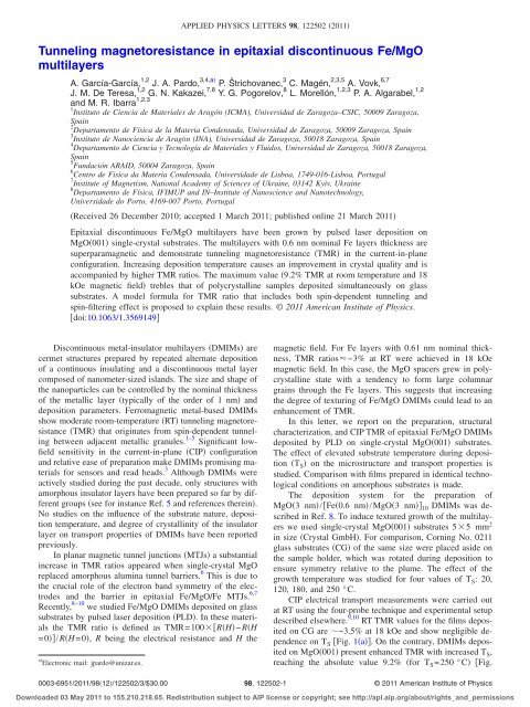
Epitaxial discont<strong>in</strong>uous <strong>Fe</strong>/<strong>MgO</strong> multilayers have been grown by pulsed laser deposition on<br />
<strong>MgO</strong>�001� s<strong>in</strong>gle-crystal substrates. The multilayers with 0.6 nm nom<strong>in</strong>al <strong>Fe</strong> layers thickness are<br />
superparamagnetic and demonstrate tunnel<strong>in</strong>g <strong>magnetoresistance</strong> �TMR� <strong>in</strong> the current-<strong>in</strong>-plane<br />
configuration. Increas<strong>in</strong>g deposition temperature causes an improvement <strong>in</strong> crystal quality and is<br />
accompanied by higher TMR ratios. The maximum value �9.2% TMR at room temperature and 18<br />
kOe magnetic field� trebles that of polycrystall<strong>in</strong>e samples deposited simultaneously on glass<br />
substrates. A model formula for TMR ratio that <strong>in</strong>cludes both sp<strong>in</strong>-dependent tunnel<strong>in</strong>g and<br />
sp<strong>in</strong>-filter<strong>in</strong>g effect is proposed to expla<strong>in</strong> these results. © 2011 American Institute of Physics.<br />
�doi:10.1063/1.3569149�<br />
Discont<strong>in</strong>uous metal-<strong>in</strong>sulator multilayers �DMIMs� are<br />
cermet structures prepared by repeated alternate deposition<br />
of a cont<strong>in</strong>uous <strong>in</strong>sulat<strong>in</strong>g and a discont<strong>in</strong>uous metal layer<br />
composed of nanometer-sized islands. The size and shape of<br />
the nanoparticles can be controlled by the nom<strong>in</strong>al thickness<br />
of the metallic layer �typically of the order of 1 nm� and<br />
deposition parameters. <strong>Fe</strong>rromagnetic metal-based DMIMs<br />
show moderate room-temperature �RT� tunnel<strong>in</strong>g <strong>magnetoresistance</strong><br />
�TMR� that orig<strong>in</strong>ates from sp<strong>in</strong>-dependent tunnel<strong>in</strong>g<br />
between adjacent metallic granules. 1–5 Significant lowfield<br />
sensitivity <strong>in</strong> the current-<strong>in</strong>-plane �CIP� configuration<br />
and relative ease of preparation make DMIMs promis<strong>in</strong>g materials<br />
for sensors and read heads. 3 Although DMIMs were<br />
actively studied dur<strong>in</strong>g the past decade, only structures with<br />
amorphous <strong>in</strong>sulator layers have been prepared so far by different<br />
groups �see for <strong>in</strong>stance Ref. 5 and references there<strong>in</strong>�.<br />
No studies on the <strong>in</strong>fluence of the substrate nature, deposition<br />
temperature, and degree of crystall<strong>in</strong>ity of the <strong>in</strong>sulator<br />
layer on transport properties of DMIMs have been reported<br />
previously.<br />
In planar magnetic tunnel junctions �MTJs� a substantial<br />
<strong>in</strong>crease <strong>in</strong> TMR ratios appeared when s<strong>in</strong>gle-crystal <strong>MgO</strong><br />
replaced amorphous alum<strong>in</strong>a tunnel barriers. 6 This is due to<br />
the crucial role of the electron band symmetry of the electrodes<br />
and the barrier <strong>in</strong> <strong>epitaxial</strong> <strong>Fe</strong>/<strong>MgO</strong>/<strong>Fe</strong> MTJs. 6,7<br />
Recently, 8–10 we studied <strong>Fe</strong>/<strong>MgO</strong> DMIMs deposited on glass<br />
substrates by pulsed laser deposition �PLD�. In these materials<br />
the TMR ratio is def<strong>in</strong>ed as TMR=100��R�H�−R�H<br />
=0��/R�H=0�, R be<strong>in</strong>g the electrical resistance and H the<br />
a� Electronic mail: jpardo@unizar.es.<br />
APPLIED PHYSICS LETTERS 98, 122502 �2011�<br />
magnetic field. For <strong>Fe</strong> layers with 0.61 nm nom<strong>in</strong>al thickness,<br />
TMR ratios�−3% at RT were achieved <strong>in</strong> 18 kOe<br />
magnetic field. In this case, the <strong>MgO</strong> spacers grew <strong>in</strong> polycrystall<strong>in</strong>e<br />
state with a tendency to form large columnar<br />
gra<strong>in</strong>s through the <strong>Fe</strong> layers. This suggests that <strong>in</strong>creas<strong>in</strong>g<br />
the degree of textur<strong>in</strong>g of <strong>Fe</strong>/<strong>MgO</strong> DMIMs could lead to an<br />
enhancement of TMR.<br />
In this letter, we report on the preparation, structural<br />
characterization, and CIP TMR of <strong>epitaxial</strong> <strong>Fe</strong>/<strong>MgO</strong> DMIMs<br />
deposited by PLD on s<strong>in</strong>gle-crystal <strong>MgO</strong>�001� substrates.<br />
The effect of elevated substrate temperature dur<strong>in</strong>g deposition<br />
�T S� on the microstructure and transport properties is<br />
studied. Comparison with films prepared <strong>in</strong> identical technological<br />
conditions on amorphous substrates is made.<br />
The deposition system for the preparation of<br />
<strong>MgO</strong>�3 nm�/�<strong>Fe</strong>�0.6 nm�/<strong>MgO</strong>�3 nm�� 10 DMIMs was described<br />
<strong>in</strong> Ref. 8. To <strong>in</strong>duce textured growth of the multilayers<br />
we used s<strong>in</strong>gle-crystal <strong>MgO</strong>�001� substrates 5�5 mm 2<br />
<strong>in</strong> size �Crystal GmbH�. For comparison, Corn<strong>in</strong>g No. 0211<br />
glass substrates �CG� of the same size were placed aside on<br />
the sample holder, which was rotated dur<strong>in</strong>g deposition to<br />
ensure symmetry relative to the plume. The effect of the<br />
growth temperature was studied for four values of T S: 20,<br />
120, 180, and 250 °C.<br />
CIP electrical transport measurements were carried out<br />
at RT us<strong>in</strong>g the four-probe technique and experimental setup<br />
described elsewhere. 9,10 RT TMR values for the films deposited<br />
on CG are �−3.5% at 18 kOe and show negligible dependence<br />
on T S �Fig. 1�a��. On the contrary, DMIMs deposited<br />
on <strong>MgO</strong>�001� present enhanced TMR with <strong>in</strong>creased T S,<br />
reach<strong>in</strong>g the absolute value 9.2% �for T S=250 °C� �Fig.<br />
0003-6951/2011/98�12�/122502/3/$30.00 98, 122502-1<br />
© 2011 American Institute of Physics<br />
Downloaded 03 May 2011 to 155.210.218.65. Redistribution subject to AIP license or copyright; see http://apl.aip.org/about/rights_and_permissions
122502-2 García-García et al. Appl. Phys. Lett. 98, 122502 �2011�<br />
FIG. 1. �Color onl<strong>in</strong>e� RT TMR vs applied magnetic field �H� measured for<br />
<strong>Fe</strong> �0.6 nm�/<strong>MgO</strong> �3 nm� DMIMs deposited on �a� CG and �b� <strong>MgO</strong>�001�<br />
substrates at the <strong>in</strong>dicated values of T S.<br />
1�b��. Structural and magnetic characterization of the films<br />
reveals the cause of this <strong>in</strong>crease.<br />
Cross-section high-resolution transmission electron microscopy<br />
�HRTEM� <strong>in</strong>vestigations of the samples grown on<br />
<strong>MgO</strong>�001� and CG were carried out <strong>in</strong> a FEI Tecnai F30<br />
transmission electron microscope operated at 300 kV. All our<br />
samples deposited on CG are polycrystall<strong>in</strong>e, as is the case<br />
for those reported earlier <strong>in</strong> Ref. 8. On the contrary, the four<br />
samples on <strong>MgO</strong>�001� show <strong>epitaxial</strong> growth of <strong>MgO</strong> alternat<strong>in</strong>g<br />
with <strong>Fe</strong> layers and with structural coherency along the<br />
whole thickness of the multilayer, even for T S=20 °C �Fig.<br />
2�. The crystal coherence shown <strong>in</strong> this HRTEM crosssection<br />
has never been observed before <strong>in</strong> DMIMs,<br />
due to the polycrystall<strong>in</strong>e or amorphous nature of both the<br />
metal granules and <strong>in</strong>sulat<strong>in</strong>g matrix. Dislocations and<br />
other structural defects caused by lattice mismatch<br />
between <strong>MgO</strong> and <strong>Fe</strong> �Ref. 6� can be seen at high magnification.<br />
Although the crystal orientation of <strong>Fe</strong> cannot be elucidated<br />
from our observations, three-dimensional epitaxy between<br />
<strong>Fe</strong> islands and <strong>MgO</strong> matrix would be possible through<br />
FIG. 2. HRTEM cross-section image of the <strong>Fe</strong> �0.6 nm�/<strong>MgO</strong> �3 nm�<br />
DMIM deposited at 20 °C on <strong>MgO</strong>�001�.<br />
FIG. 3. �Color onl<strong>in</strong>e� �a� �/2� scans measured <strong>in</strong> the <strong>Fe</strong> �0.6 nm�/<strong>MgO</strong> �3<br />
nm� DMIMs deposited on <strong>MgO</strong>�001� at the values of T S <strong>in</strong>dicated. �b�<br />
Average <strong>in</strong>terplanar spac<strong>in</strong>g d obta<strong>in</strong>ed from Bragg’s law at the film diffraction<br />
maxima <strong>in</strong> �a� �circles�, and full width at half-maximum of the rock<strong>in</strong>g<br />
curves taken at the same maxima �squares�. The cont<strong>in</strong>uous l<strong>in</strong>es are guides<br />
to the eye.<br />
the <strong>epitaxial</strong> relationships reported <strong>in</strong> coevaporated granular<br />
<strong>Fe</strong>/<strong>MgO</strong> cermets: 11<br />
�001��110�<strong>Fe</strong> ��001��100�<strong>MgO</strong> and<br />
�011��100�<strong>Fe</strong> ��001��100�<strong>MgO</strong>. TEM micrographs provide only some clues about the<br />
discont<strong>in</strong>uous nature of the <strong>Fe</strong> layers �Fig. 2�, due to the fact<br />
that TEM specimens’ thickness �a few tens of nanometers� is<br />
much larger than typical <strong>Fe</strong> granule size. This causes superimposition<br />
of the granules over the specimen thickness and<br />
gives the impression of a cont<strong>in</strong>uous <strong>Fe</strong> layer <strong>in</strong> many areas.<br />
<strong>Fe</strong> is well known to follow three-dimensional �Volmer–<br />
Weber� nucleation and growth on <strong>MgO</strong>�001� �Ref. 12�, so<br />
that only for sufficient thickness, typically above 1 nm, cont<strong>in</strong>uous<br />
films appear as a result of islands coalescence. 12–14<br />
The discont<strong>in</strong>uous nature of the <strong>Fe</strong> layers was confirmed<br />
by zero-field cooled �ZFC� and field cooled �FC� magnetic<br />
susceptibility measurements. They were carried out us<strong>in</strong>g a<br />
Quantum Design MPMS magnetometer <strong>in</strong> H=50 Oe and <strong>in</strong><br />
the temperature range 5–300 K. A maximum associated with<br />
progressive unblock<strong>in</strong>g of small superparamagnetic granules<br />
is present on ZFC curves for all the <strong>in</strong>vestigated samples.<br />
The position of the maximum is shifted toward lower temperature<br />
and its width decreases with <strong>in</strong>creas<strong>in</strong>g TS. The bifurcation<br />
temperature, TB �the one below which the ZFC and<br />
FC curves split� for samples deposited on <strong>MgO</strong>�001� monotonically<br />
decreases from 180 to 45 K as TS <strong>in</strong>creases from 20<br />
to 250 °C. Very similar variation <strong>in</strong> TB from 200 K to 50 K<br />
for the same deposition conditions was found for the samples<br />
on CG substrates. As the same amount of <strong>Fe</strong> has been deposited<br />
<strong>in</strong> all the samples, reduction <strong>in</strong> TB po<strong>in</strong>ts that <strong>in</strong>creas<strong>in</strong>g<br />
TS leads to higher nucleation density, 15 average <strong>Fe</strong><br />
granule size decrease, and narrow<strong>in</strong>g of the particle sizes<br />
distribution. 8 The detailed analysis of magnetic properties<br />
and <strong>Fe</strong> particles size and shape evolution with TS will be the<br />
subject of a forthcom<strong>in</strong>g publication.<br />
The evolution of the crystal quality of the multilayers<br />
deposited on <strong>MgO</strong>�001� with TS was studied by x-ray diffraction<br />
us<strong>in</strong>g a Bruker D8 high-resolution diffractometer<br />
with Cu K�1 radiation. Symmetrical �/2� scans <strong>in</strong> the 2�<br />
range 41°–44° �Fig. 3�a�� show the 002 reflection from the<br />
<strong>MgO</strong> substrate at 2��42.9° and a strong reflection around<br />
2��42° which is the result of the coherent growth of cont<strong>in</strong>uous<br />
<strong>epitaxial</strong> <strong>MgO</strong> with vary<strong>in</strong>g degrees of lattice distor-<br />
Downloaded 03 May 2011 to 155.210.218.65. Redistribution subject to AIP license or copyright; see http://apl.aip.org/about/rights_and_permissions
122502-3 García-García et al. Appl. Phys. Lett. 98, 122502 �2011�<br />
tion for different values of T S. In Fig. 3�b�, we show the<br />
average <strong>in</strong>terplanar spac<strong>in</strong>g <strong>in</strong> the out-of-plane direction obta<strong>in</strong>ed<br />
through Bragg’s law, d=�/2�s<strong>in</strong> � �� is the x-rays<br />
wavelength�, which shows a tendency to approach the bulk<br />
<strong>MgO</strong> value d=2.106 Å upon <strong>in</strong>creas<strong>in</strong>g T S. This might be<br />
related to the decrease <strong>in</strong> the <strong>Fe</strong> particles size deduced from<br />
magnetic measurements. The width of the rock<strong>in</strong>g curves<br />
taken at the maximum of the film reflection decreases with<br />
<strong>in</strong>creas<strong>in</strong>g T S �Fig. 3�b��, <strong>in</strong>dicat<strong>in</strong>g improvement of the<br />
crystal quality. The coherence length determ<strong>in</strong>ed through<br />
Scherrer equation agrees with the multilayer thickness deduced<br />
from x-ray reflectivity for any value of T S, thus, confirm<strong>in</strong>g<br />
that the multilayers show crystal coherence along<br />
their whole thickness.<br />
Experimental data allow us to conclude that <strong>in</strong>creas<strong>in</strong>g<br />
T S causes both an enhanced degree of �001� textur<strong>in</strong>g of<br />
<strong>MgO</strong> and a decrease <strong>in</strong> the average <strong>Fe</strong> granule size. At the<br />
same time, an <strong>in</strong>crease <strong>in</strong> TMR value is observed. It has been<br />
previously shown that <strong>MgO</strong> �001�-oriented barriers produce<br />
electron band symmetry filter<strong>in</strong>g. 6,7 Thus, electrons from � 1<br />
band from <strong>Fe</strong>�001� electrodes tunnel more efficiently through<br />
<strong>MgO</strong>�001� than the � 2 and � 5 ones. The absence of � 1 <strong>in</strong> the<br />
sp<strong>in</strong>-down subband of <strong>Fe</strong>�001� causes the large TMR ratios<br />
observed <strong>in</strong> <strong>epitaxial</strong> <strong>Fe</strong>�001�/<strong>MgO</strong>�001�/<strong>Fe</strong>�001� MTJs. It is<br />
feasible that the <strong>in</strong>crease <strong>in</strong> the degree of �001� textur<strong>in</strong>g <strong>in</strong><br />
our <strong>Fe</strong>/<strong>MgO</strong> DMIMs favors this type of band symmetry filter<strong>in</strong>g<br />
effect and leads to TMR enhancement. On the contrary,<br />
the samples deposited on CG grow without preferential<br />
orientation and show a negligible variation <strong>in</strong> TMR with T S.<br />
These effects can be modeled through<br />
P 2 + P�<br />
TMR =<br />
1+P2 �1 − cos ��, �1�<br />
+2P�<br />
an extension of the known Inoue–Maekawa formula 16 for<br />
TMR, with sp<strong>in</strong> polarization P and average angle � between<br />
adjacent granules moments, enhanced by a nonzero sp<strong>in</strong>filter<strong>in</strong>g<br />
factor �=�t ↑−t ↓�/�t ↑+t ↓�, where t� is the full tunnel<br />
rate <strong>in</strong> � sp<strong>in</strong> channel. This formula expla<strong>in</strong>s the lower TMR<br />
for samples grown at 20 °C on <strong>MgO</strong> substrate −� is still too<br />
small to give advantage and � is lower than for samples<br />
grown on glass due to the similar orientation of crystall<strong>in</strong>e<br />
anisotropy axis <strong>in</strong> neighbor<strong>in</strong>g granules because of the <strong>epitaxial</strong><br />
growth. For P=0.3 �Ref. 9� the change <strong>in</strong> � from 0 to<br />
1 will <strong>in</strong>crease TMR by a factor of 3, <strong>in</strong> good agreement with<br />
our results on <strong>MgO</strong>�001� substrates.<br />
In conclusion, <strong>epitaxial</strong> <strong>Fe</strong>/<strong>MgO</strong> DMIMs have been prepared.<br />
Elevated deposition temperature causes the improve-<br />
ment <strong>in</strong> crystal quality and is accompanied by an <strong>in</strong>crease <strong>in</strong><br />
TMR. The absolute value of TMR ratio 9.2% at RT <strong>in</strong> 18<br />
kOe has been achieved, and higher values may be expected<br />
by optimiz<strong>in</strong>g deposition conditions and measurement geometry.<br />
This result demonstrates an alternative route to prepare<br />
DMIMs with improved magnetotransport properties.<br />
We acknowledge the Laboratorio de Microscopías Avanzadas<br />
�LMA�. F<strong>in</strong>ancial support by Spanish M<strong>in</strong>istry of Science<br />
�through project No. MAT2008-06567-C02 <strong>in</strong>clud<strong>in</strong>g<br />
FEDER fund<strong>in</strong>g� and by the Aragón Regional Government<br />
�through projects E26 and PI059/08� is acknowledged. Work<br />
of A.V. and G.N.K. was supported by Portuguese FCT<br />
through “Ciencia 2008” and “Ciencia 2007” programs, respectively.<br />
1 S. Sankar, S. B. Dieny, and A. E. Berkowitz, J. Appl. Phys. 81, 5512<br />
�1997�.<br />
2 B. Dieny, S. Sankar, M. R. McCartney, D. J. Smith, P. Bayle-Guillemaud,<br />
and A. E. Berkowitz, J. Magn. Magn. Mater. 185, 283 �1998�.<br />
3 G. N. Kakazei, Y. G. Pogorelov, A. M. L. Lopes, J. B. Sousa, S. Cardoso,<br />
P. P. Freitas, M. M. Pereira de Azevedo, and E. Snoeck, J. Appl. Phys. 90,<br />
4044 �2001�.<br />
4 R. Bručas, M. Hanson, R. Gunnarsson, E. Wahlström, M. van Kampen, B.<br />
Hjörvarsson, H. Lidbaum, and K. Leifer, J. Appl. Phys. 101, 073907<br />
�2007�.<br />
5 H. G. Silva, A. M. Pereira, J. M. Teixeira, J. M. Moreira, G. N. Kakazei,<br />
J. P. Araújo, Y. G. Pogorelov, J. B. Sousa, M. E. Braga, B. Raquet, H.<br />
Rakoto, C. Gatel, E. Snoeck, S. Cardoso, and P. P. Freitas, Phys. Rev. B<br />
82, 144432 �2010�.<br />
6 S. Yuasa, T. Nagahama, A. Fukushima, Y. Suzuki, and K. Ando, Nature<br />
Mater. 3, 868 �2004�.<br />
7 C. Tiusan, F. Greullet, M. Hehn, F. Montaigne, S. Andrieu, and A. Schuhl,<br />
J. Phys.: Condens. Matter 19, 165201 �2007�.<br />
8 A. García-García, A. Vovk, J. A. Pardo, P. Štrichovanec, C. Magén, E.<br />
Snoeck, P. A. Algarabel, J. M. De Teresa, L. Morellón, and M. R. Ibarra,<br />
J. Appl. Phys. 105, 063909 �2009�.<br />
9 A. García-García, A. Vovk, J. A. Pardo, P. Štrichovanec, P. A. Algarabel,<br />
C. Magén, J. M. De Teresa, L. Morellón, and M. R. Ibarra, J. Appl. Phys.<br />
107, 033704 �2010�.<br />
10 A. García-García, A. Vovk, P. Štrichovanec, J. A. Pardo, C. Magén, P. A.<br />
Algarabel, J. M. De Teresa, L. Morellón, and M. R. Ibarra, J. Phys.:<br />
Condens. Matter 22, 056003 �2010�.<br />
11 M. Nagao, N. Tanaka, and K. Mihama, Jpn. J. Appl. Phys., Part 2 25,<br />
L614 �1986�.<br />
12 G. Fahsold, A. Pucci, and K.-H. Rieder, Phys. Rev. B 61, 8475�2000�.<br />
13 R. Reit<strong>in</strong>ger, B. Sepiol, G. Vogl, B. Pfau, L.-M. Stadler, S. Stankov, F.<br />
Zontone, N. Spiridis, and J. Korecki, J. Appl. Phys. 102, 034310 �2007�.<br />
14 S. Adenwalla, Y. S. Park, G. P. <strong>Fe</strong>lcher, and M. Teitelman, J. Appl. Phys.<br />
76, 6443 �1994�.<br />
15 G. N. Kakazei, Y. G. Pogorelov, J. A. M. Santos, J. B. Sousa, P. P. Freitas,<br />
S. Cardoso, N. A. Lesnik, and P. E. Wigen, J. Magn. Magn. Mater. 266,<br />
57 �2003�.<br />
16 J. I. Inoue and S. Maekawa, Phys. Rev. B 53, R11927 �1996�.<br />
Downloaded 03 May 2011 to 155.210.218.65. Redistribution subject to AIP license or copyright; see http://apl.aip.org/about/rights_and_permissions