

MONKEY LADDER SWING – A25189 - Climbing Frames Australia
MONKEY LADDER SWING – A25189 - Climbing Frames Australia
MONKEY LADDER SWING – A25189 - Climbing Frames Australia

You also want an ePaper? Increase the reach of your titles
YUMPU automatically turns print PDFs into web optimized ePapers that Google loves.
MK END <strong>LADDER</strong><br />
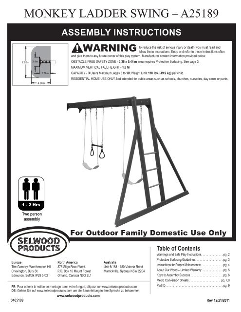
<strong>SWING</strong> ASSY <strong>MONKEY</strong> <strong>LADDER</strong> <strong>SWING</strong> <strong>–</strong> <strong>A25189</strong><br />
7.92m<br />
2.4m<br />
1 - 2 Hrs<br />
4.78m<br />
Two person<br />
assembly<br />
2.78m<br />
Europe<br />
The Granary, Weathercock Hill<br />
Chevington, Bury St<br />
Edmunds, Suffolk IP29 5RG<br />
ASSEMBLY INSTRUCTIONS<br />
To reduce the risk of serious injury or death, you must read and<br />
follow these instructions. Keep and refer to these instructions often<br />
and give them to any future owner of this play system. Manufacturer contact information provided below.<br />
OBSTACLE FREE SAFETY ZONE - 3.36 x 5.44 m area requires Protective Surfacing. See page 3.<br />
MAXIMUM VERTICAL FALL HEIGHT - 1.8 M<br />
CAPACITY - 3 Users Maximum, Ages 3 to 10; Weight Limit 110 lbs. (49.9 kg) per child.<br />
RESIDENTIAL HOME USE ONLY. Not intended for public areas such as schools, churches, nurseries, day cares or parks.<br />
North America<br />
375 Sligo Road West.<br />
P.O. Box 10 Mount Forest<br />
Ontario, Canada N0G 2L1<br />
WARNING<br />
<strong>Australia</strong><br />
Unit 6/168 - 180 Victoria Road<br />
Marrickville, Sydney NSW 2204<br />
FR: Pour obtenir la notice de montage dans votre langue, cliquez sur www.selwoodproducts.com<br />
DE: Gehen Sie auf www.selwoodproducts.com um die Bauanleitung in thre Sprache zu bekommen.<br />
www.selwoodproducts.com<br />
3405189<br />
Table of Contents<br />
Warnings and Safe Play Instructions. . . . . . . . . . . . . . . pg. 2<br />
Protective Surfacing Guidelines. . . . . . . . . . . . . . . . . . . pg. 3<br />
Instructions for Proper Maintenance . . . . . . . . . . . . . . . pg. 4<br />
About Our Wood <strong>–</strong> Limited Warranty . . . . . . . . . . . . . . pg. 5<br />
Keys to Assembly Success . . . . . . . . . . . . . . . . . . . . . . pg. 6<br />
Metric Conversion Sheets . . . . . . . . . . . . . . . . . . . . . pg. 7,8<br />
Part ID . . . . . . . . . . . . . . . . . . . . . . . . . . . . . . . . . . . . . . . pg. 9<br />
Rev 12/21/2011
Warnings and Safe Play Instructions<br />
CONTINUOUS ADULT SUPERVISION REQUIRED. Most serious injuries and deaths on playground equipment have occurred<br />
while children were unsupervised! Our products are designed to meet mandatory and voluntary safety standards. Complying<br />
with all warnings and recommendations in these instructions will reduce the risk of serious or fatal injury to children using<br />
this play system. Go over the warnings and safe play instructions regularly with your children and make certain that they<br />
understand and follow them. Remember on-site adult supervision is required for children of all ages.<br />
SERIOUS HEAD INJURY HAZARD<br />
Installation over concrete, asphalt, dirt, grass, carpet<br />
and other hard surface creates a risk of serious injury<br />
or death from falls to the ground. Install and maintain<br />
shock absorbing material under and around play-set as<br />
recommended on page 3 of these instructions.<br />
COLLISION HAZARD<br />
Place play-set on level ground at least 6 feet from any<br />
obstruction such as a garage or house, fences, poles,<br />
trees, sidewalks, walls, landscape timbers, rocks,<br />
pavement, planters, garden borders, overhanging<br />
branches, laundry lines, and electrical wires. (See<br />
OBSTACLE FREE SAFETY ZONE on cover)<br />
CHOKING HAZARD<br />
Prior to assembly, this product contains small parts.<br />
DO NOT allow children less than 5 years of age near or<br />
around loose nuts, screws, washers, plastic bags and<br />
other small parts.<br />
Observe capacity limitations of your play-set. See<br />
front cover.<br />
Dress children with well fitting and full foot enclosing<br />
footwear.<br />
Teach children to sit with their full weight in the center<br />
of the swing seat to prevent erratic swing motion or<br />
falling off.<br />
Check for splintered, broken or cracked wood; missing,<br />
loose, or sharp edged hardware. Replace, tighten and or<br />
sand smooth as required prior to playing.<br />
Verify that suspended climbing ropes, rope ladders, chain<br />
or cable are secured at both ends and cannot be looped<br />
back on itself as to create an entanglement hazard.<br />
On sunny and or hot days, check the slide and other<br />
plastic rides to assure that they are not very hot as to<br />
cause burns. Cool hot slide and rides with water and wipe<br />
dry prior to using.<br />
WARNING<br />
WARNING <strong>–</strong> Safe Play Instructions<br />
2<br />
STRANGULATION HAZARD<br />
• NEVER allow children to play with ropes, clotheslines,<br />
pet leashes, cables, chains or cord-like items when using<br />
this play-set or to attach these items to play-set.<br />
• NEVER allow children to wear loose fitting clothing,<br />
ponchos, hoods, scarves, capes, necklaces, items with<br />
draw-strings, cords or ties when using this play-set.<br />
• NEVER allow children to wear bike or sport helmets<br />
when using this play-set.<br />
Failure to prohibit these items, even helmets with chin<br />
straps, increases the risk of serious injury and death to<br />
children from entanglement and strangulation.<br />
TIP OVER HAZARD<br />
Choose a level location for the equipment. This can reduce<br />
the likelihood of the play set tipping over and loose-fill<br />
surfacing materials washing away during heavy rains.<br />
DO NOT allow children to play on the play-set until the<br />
assembly is complete and the unit is properly anchored.<br />
Do not allow children to wear open toe or heel footwear<br />
like sandals, flip<strong>–</strong>flops or clogs.<br />
Do not allow children to walk, in front, between, behind<br />
or close to moving rides.<br />
Do not let children twist swing chains or ropes or loop<br />
them over the top support bar. This may reduce the<br />
strength of the chain or rope and cause premature failure.<br />
Do not let children get off rides while they are in motion.<br />
Do not permit climbing on equipment when it is wet.<br />
Do not permit rough play or use of equipment in a<br />
manner for which it was not intended. Standing on or<br />
jumping from the roof, elevated platforms, swings,<br />
climbers, ladders or slide can be dangerous.<br />
Do not allow children to swing empty rides or seats.<br />
Do not allow children to go down slide head first or<br />
run up slide.
At the factory we have added water repellent to the stain. This water repellent decreases the amount of water absorption during<br />
rain or snow thus decreasing the tension in the wood. Sunlight will break down the water repellent, so we recommend applying a<br />
water repellent on a yearly basis (see your local stain and paint supplier for a recommended product). Failure to do so can affect<br />
warranty. Also if storing the product before installation, make sure you store out of direct sunlight in a cool dry place.<br />
Selwood Products Limited Warranty<br />
Selwood Products states that the product is free from defect in materials and workmanship for a period of one (1) year from the original<br />
date of purchase. This one (1) year warranty covers all parts including wood, hardware, and accessories. All wood carries a ten (10)<br />
year warranty against rot and decay. Refer to the schedule associated with replacement of parts under this Warranty. In addition, the<br />
manufacturer will replace any parts within the first 60 days from date of purchase found to be missing from or damaged in the original<br />
packaging. This warranty applies to the original owner and registrant and is non-transferable. Regular maintenance is required to<br />
assure maximum life and performance of this product and failure by the owner to maintain the product according to the maintenance<br />
requirements may void this warranty. Maintenance guidelines are provided in the Owner’s Manual provided by Selwood Products.<br />
This Limited Warranty does not cover:<br />
• Labour for any inspection or Labour for replacement of any defective item(s)<br />
• Incidental or consequential damages<br />
• Cosmetic defects which do not affect performance or integrity of a part or the entire product<br />
• Vandalism, improper use, failure due to loading or use beyond the capacities stated in the Assembly Manual.<br />
• Acts of nature including but not limited to wind, storms, hail, floods, excessive water exposure<br />
• Improper installation including but not limited to installation on uneven, unlevel, or soft ground<br />
• Minor twisting, warping, checking, splitting, or any other natural occurring properties of wood that do not affect<br />
performance or integrity.<br />
Selwood Products states that the product has been designed for safety and quality. Any modifications made to the original product<br />
could damage the structural integrity of the unit leading to failure and possible injury. Modification voids any and all warranties and<br />
Selwood Products will accept no liability for any modified products or consequences resulting from failure of a modified product.<br />
This product is warranted for RESIDENTIAL USE ONLY. Under no circumstance should the product be used in public settings<br />
such as schools, churches, playgrounds, parks, daycares and the like. Such use may lead to product failure and potential injury. Any<br />
and all public use will void this warranty.<br />
Selwood disclaims all other representations and warranties of any kind, expressed or implied.<br />
Warranty Part Replacement Schedule:<br />
Plastic/Metal/Wood Components: 1 Year Warranty<br />
0-60 days from date from purchase: Free Parts & Free Shipping | 61 days to 1 year from purchase: Free Parts + Shipping & Handling<br />
Wooden (Wood Rot and Decay Only): 10 Year Warranty<br />
0-60 days from date from purchase: Free Parts & Free Shipping | 61 days -10 years from purchase: Free Parts + Shipping & Handling<br />
This Warranty gives you specific legal rights. You may have other rights as well which very from state to state or province to<br />
province. This warranty excludes all consequential damages, however, some states do not allow the limitation or exclusion of<br />
consequential damages, and therefore this limitation may not apply to you.<br />
Complete the registration of your Selwood Product purchase online at: www.selwoodproducts.com/warranty-registration<br />
Please refer to the back of this instruction manual for details on how to register your Selwood Products purchase.<br />
5
Square<br />
Assembly<br />
6
4.5 inches x<br />
25.4mm<br />
=<br />
114mm long<br />
3/8" (9.5mm)<br />
Flat Washer<br />
For example:<br />
BOLT LENGTH 4½ (4.5) inches long<br />
3/8"(.38) = 9.5mm Lag Screw<br />
1 inch = 25.4mm<br />
LENGTH CONVERSION<br />
5/16" (8mm)<br />
Flat Washer<br />
0.31 inches x 25.4mm = 8mm<br />
5/16"(.31) = 8mm Lag Screw<br />
1 inch = 25.4mm<br />
For example:<br />
BOLT DIAMETER 5/16 (0.31) inches<br />
HARDWARE LENGTH CHART<br />
inches vs millimetres<br />
6 152<br />
5½ 140<br />
5 127<br />
4½ 114<br />
4 102<br />
3½ 89<br />
3 76<br />
2½ 64<br />
2 51<br />
1½ 38<br />
1¼ 32<br />
1-1/8 29<br />
1 25.4<br />
7/8 22<br />
3/4 19<br />
1/2 12.7<br />
DIAMETER CONVERSION<br />
1/4" (6mm)<br />
Flat Washer<br />
1/4"(0.25) = 6mm Lag Screw<br />
7<br />
1/4" (6mm) Flat Washer<br />
1/4" (6mm)<br />
T-Nut<br />
1/4"(0.25) = 6mm Hex Bolt<br />
1/4" (6mm)<br />
Lock Washer<br />
5/16" (8mm) Lock Washer<br />
5/16" (8mm)<br />
T-Nut<br />
5/16"(.31) = 8mm Hex Bolt<br />
5/16" (8mm)<br />
Flat Washer<br />
SOLO)WAVE DESIGN HARDWARE
59.25 inches x 25.4mm =<br />
1505mm<br />
Dimensions in brackets<br />
[mm] represent millimetres.<br />
For example:<br />
BOARD LENGTH 59¼ (59.25) inches<br />
88.9<br />
3 1/2"<br />
4 x 4<br />
1 inch = 25.4mm<br />
88.9<br />
3 1/2"<br />
2 x 6<br />
LENGTH CONVERSION<br />
38.1<br />
1 1/2"<br />
136.5<br />
5 3/8"<br />
1 x 6<br />
15.9<br />
5/8"<br />
136.5<br />
5 3/8"<br />
25.4<br />
1"<br />
139.7<br />
5 1/2"<br />
5/4 x 6<br />
1 x 5<br />
34.9<br />
1 3/8"<br />
85.7<br />
3 3/8"<br />
2 x 4<br />
15.9<br />
5/8"<br />
114.3<br />
4 1/2"<br />
1 x 4<br />
8<br />
25.4<br />
1" 5/4 x 5<br />
2 x 3<br />
15.9<br />
85.7<br />
5/8" 3 3/8"<br />
114.3<br />
4 1/2"<br />
34.9<br />
1 3/8"<br />
63.5<br />
2 1/2"<br />
1 x 3<br />
25.4<br />
1"<br />
88.9<br />
3 1/2"<br />
5/4 x 4<br />
2<br />
x 2<br />
15.9<br />
5/8"<br />
60.3<br />
2 3/8"<br />
38.1<br />
1 1/2"<br />
38.1<br />
1 1/2"<br />
1 x 2<br />
15.9<br />
5/8"<br />
34.9<br />
1 3/8"<br />
25.4<br />
1"<br />
5/4 x 3<br />
11.1<br />
.44<br />
1/2 x 4<br />
63.5<br />
2 1/2"<br />
82.6<br />
3 1/4"<br />
SOLO)WAVE DESIGN WOOD PROFILES
Part Identification (Reduced Part Size)<br />
A1<br />
A2<br />
A3<br />
A4<br />
A5<br />
A6<br />
A7<br />
A8<br />
A9<br />
A10<br />
Triangle Plates<br />
4 pk -Green<br />
3200184<br />
(1) MK Front Beam 2 x 6 x 94" 3632014<br />
(1) MK Back Beam 2 x 6 x 94" 3632015<br />
(1) SW Mount 2 x 4 x 38 -1/8" 3641861<br />
(1) Ground Rail 5/4 x 4 x 93 13/16" 3642018<br />
(2) End Post 2 x 4 x 83 -1/2" 3642016<br />
(2) End Diagonal 2 x 3 x 73 -7/16" 3642017<br />
(2) Ground Stake 1-1/4 x 1-1/2 x 14" 3650318<br />
(1) SW Block 4 x 4 x 17" 3642019<br />
(3) Dowel Tennon 1 1/8 x 18 5/8" 3681858<br />
(6) Dowel -Tennon 1 1/8" x 15 7/8" 3681578<br />
Acro Rope<br />
2 pk -with<br />
Quick Links<br />
3502024<br />
2X Acro Handle<br />
Green 9320131<br />
1X Steel Acro Bar 14½"<br />
Green 9200131<br />
2x 42" Belt Swing<br />
Yellow - Welded Chain<br />
3724943<br />
9<br />
8pk Plastic Swing Hanger<br />
Cover 3793000<br />
Hardware at<br />
Top of Beam<br />
Hardware at<br />
Bottom of Beam<br />
Nominal Size<br />
2" x 6"<br />
2" x 4"<br />
2" x 3"<br />
2" x 2"<br />
5/4" x 4"<br />
4" x 4"<br />
Actual Size<br />
1½" x 5⅜"<br />
1⅜" x 3⅜"<br />
1⅜" x 2½"<br />
1½" x 1½"<br />
1" x 3½"<br />
3½" x 3½"<br />
8 pk Swing Hanger<br />
Bolt Thru.<br />
3202002
Part Identification (Reduced Part Size)<br />
S3<br />
S4<br />
G1<br />
G9<br />
G10<br />
G11<br />
G5<br />
G7<br />
H7<br />
(10) #8 x 2-1/2" Wood Screw ( 9290522)<br />
(10) #8 x 3" Wood Screw ( 9290530)<br />
(20) 5/16" Flat Washer<br />
(9251300)<br />
(20) 5/16" Lock Washer<br />
(9253300)<br />
(7) Hex Bolt 5/16 x 1-1/2" (9277312)<br />
5/16" Lock Washer - 5/16" Flat Washer - 5/16" T-Nut<br />
(2) Hex Bolt 5/16 x 2-1/2" (9277322)<br />
5/16" Lock Washer - 5/16" Flat Washer - 5/16" T-Nut<br />
(5) Hex Bolt 5/16 x 3" (9277330)<br />
5/16" Lock Washer, 5/16" Flat Washer - 5/16" T-Nut<br />
(1) Hex Bolt 5/16 x 3-1/2" (9277332) 5/16" Lock Washer<br />
5/16" Flat Washer - 5/16" T-Nut<br />
(3) Hex Bolt 5/16 x 4-1/2" (9277342) 5/16" Lock Washer<br />
5/16" Flat Washer - 5/16" T-Nut<br />
(2) Hex Bolt 5/16 x 5-1/2" (9277352)<br />
(4) 1/4" Flat Washer<br />
(9251200)<br />
(4) Hex Bolt 1/4 x 5-1/2" (9277252) 1/4" Lock Washer - 1/4" Flat Washer - 1/4" T-Nut<br />
10<br />
(20) 5/16" T-Nut<br />
(9285300)<br />
(4) 1/4" T-Nut<br />
(9285200)<br />
(4) 1/4" Lock Washer<br />
(9253200)
PRODUCT NUMBER: <strong>A25189</strong><br />
CARTON I.D. STAMP: __ __ __ __ __ 14459 ___ (Box 1)<br />
CARTON I.D. STAMP: __ __ __ __ __ 14459 ___ (Box 2)<br />
CARTON I.D. STAMP: __ __ __ __ __ 14459 ___ (Box 3)<br />
CARTON I.D. STAMP: __ __ __ __ __ 14459 ___ (Box 4)<br />
CARTON I.D. STAMP: __ __ __ __ __ 14459 ___ (Box 5)<br />
CARTON I.D. STAMP: __ __ __ __ __ 14459 ___ (Box 6)<br />
If you have missing, damaged or require replacement parts DO NOT contact your<br />
retailer. Please visit www.selwoodproducts.com and select the Parts Centre.<br />
You can then complete a quick online order form or make direct contact with the<br />
Selwood Products Part Team.<br />
www.selwoodproducts.com<br />
11
Step 1: Monkey Swing Rail Assembly<br />
Note: Pre-drill all holes using a 1/8” drill bit before installing the wood screws.<br />
A: Insert 6 (A10) 1-1/8 x 15-7/8” Dowels into (A1) MK Front Beam and (A2) MK Back Beam as shown in fig.<br />
1.1. Make sure the pilot holes are at the top of each board.<br />
B: Make sure shoulder of dowel is against each beam before pre-drilling pilot holes. Drill 1/8” pilot holes<br />
through the beams and into the dowels to prevent splitting. (fig 1.2)<br />
C: Attach (A10) 1-1/8 x 15-7/8” Dowels to both beams with 2 (S4) #8 x 3” Wood Screws per dowel as shown<br />
in fig. 1.1.<br />
Fig. 1.1<br />
Top Side showing<br />
A2<br />
End Ladder Side<br />
Wood Parts<br />
A1<br />
6 x A10 Dowel Tennon 1-1/8 x 15-7/8”<br />
1 x A1 MK Front Beam 2 x 6 x 94”<br />
1 x A2 MK Back Beam 2 x 6 x 94”<br />
Fig. 1.2<br />
S4<br />
Make sure shoulder is against<br />
beam before drilling holes<br />
Hardware<br />
12 x S4 # 8 x 3” Wood Screw<br />
12<br />
S4<br />
A10<br />
A10<br />
x 6<br />
Fort Side
Step 2: Monkey End Ladder Assembly<br />
Part 1<br />
Note: Pre-drill all holes using a 1/8” drill bit before installing the wood screws.<br />
A: Insert 3 (A9) 1-1/8 x 18-5/8” Dowels into 2 (A5) End Posts as shown in fig. 2.1.<br />
B: Make sure shoulder of dowel is against each post before pre-drilling pilot holes. Drill 1/8” pilot holes<br />
through the posts and into the dowel to prevent splitting. (fig. 2.2)<br />
C: Attach (A9) 1-1/8 x 18-5/8” Dowels to both posts with 3 (S3) #8 x 2-1/2” Wood Screws per post. One screw<br />
is installed from top of the posts and the other from the bottom as shown in fig. 2.1.<br />
Wood Parts<br />
S3<br />
Fig. 2.2<br />
Fig. 2.1<br />
A9<br />
Make sure shoulder is against<br />
post before drilling holes<br />
Hardware<br />
3 x A9 Dowel Tennon 1-1/8 x 18-5/8”<br />
6 x S3 # 8 x2-1/2” Wood Screw<br />
2 x A5<br />
End Post 2 x 4 x 83-1/2”<br />
13<br />
A5<br />
S3<br />
A9<br />
A5
Step 2: Monkey End Ladder Assembly<br />
Part 2<br />
D: To bottom of the posts attach (A4) Ground Rail with 2 (G5) 5/16 x 4-1/2” Hex Bolts (with lock washer, flat<br />
washer and t-nut). Be sure to keep the bolts loose. (fig. 2.3)<br />
E: Attach 1 (A6) End Diagonal to each end of (A4) Ground Rail with 1 (G9) 5/16 x 2-1/2” Hex Bolt (with lock<br />
washer, flat washer and t-nut) per side, keeping the bolts loose. (fig. 2.3 and 2.4)<br />
F: Make sure the assembly is square and then attach each (A6) End Diagonal to each (A5) End Post with 1<br />
(G10) 5/16 x 3” Hex Bolt (with lock washer, flat washer and t-nut) per diagonal.<br />
G: Tighten all bolts from Step 2.<br />
G9<br />
A4<br />
Fig. 2.4<br />
Wood Parts<br />
A6<br />
G5<br />
Fig. 2.3<br />
A6<br />
G9<br />
G10<br />
Hardware<br />
1 x A4 Ground Rail 5/4 x 4 x 93-13/16” 2 x G9 5/16 x 2-1/2” Hex Bolt (5/16” lock washer, 5/16” flat washer, 5/16” t-nut)<br />
2 x A6 End Diagonal 2 x 3 x 73-7/16”<br />
2 x G10 5/16 x 3” Hex Bolt (5/16” lock washer, 5/16” flat washer, 5/16” t-nut)<br />
2 x G5 5/16 x 4-1/2” Hex Bolt (5/16” lock washer, 5/16” flat washer, 5/16” t-nut)<br />
14<br />
A5<br />
G9<br />
G10<br />
A6
Step 3: Attach Triangle Plates<br />
A: Place Monkey Swing Rail Assembly on the ground with the countersunk holes facing down. (fig. 3.1)<br />
B: Attach 1 Triangle Plate to the ends of both (A1) MK Front Beam and (A2) MK Back Beam, in the places<br />
shown in fig. 3.1, using 1 (G1) 5/16 x 1-1/2” Hex Bolt (with lock washer, flat washer and t-nut) in the hole<br />
indicated in fig. 3.1 & 3.2. Correct Triangle placement and hole usage is very important.<br />
C: Attach 1 (H7) 1/4 x 5-1/2” Hex Bolt (with lock washer, flat washer and t-nut) to the ends of both (A1) MK Front<br />
Beam and (A2) MK Back Beam. The bolts do not attach to anything, but MUST be installed to prevent splitting<br />
and checking of wood. (fig. 3.1 & 3.2)<br />
H7<br />
Important!<br />
End Ladder Side<br />
(With Overhang)<br />
G1<br />
H7<br />
A2<br />
G1<br />
G1<br />
Fig. 3.2<br />
Fort Side<br />
G1<br />
(hidden behind board)<br />
A2<br />
Triangle<br />
Plate<br />
A1<br />
Hardware<br />
Fig. 3.1<br />
Bottom Side showing<br />
A1<br />
Countersunk holes on<br />
side not showing.<br />
G1<br />
4 x H7 1/4 x 5-1/2” Hex Bolt<br />
(1/4” lock washer, 1/4” flat washer, 1/4” t-nut)<br />
4 x G1 5/16 x 1-1/2” Hex Bolt<br />
(5/16” lock washer, 5/16” flat washer, 5/16” t-nut)<br />
15<br />
H7<br />
Important!<br />
Fort Side<br />
(No Overhang)<br />
Other Parts<br />
G1<br />
1 x Triangle Plate (pkg of 4)
Step 4: Attach Swing Hangers<br />
Make sure triangle is<br />
tight against beam<br />
16<br />
Warning: For your child’s safety,<br />
orientate the swing hangers as<br />
shown to ensure your swing will<br />
have proper swing motion when<br />
installed. Failure to do so could<br />
result in premature failure of the<br />
swing hanger or swing chain.<br />
A: In the holes shown in fig. 4.1 install 4 Bolt-Thru Swing Hangers in both (A1) MK Front Beam and (A2) MK<br />
Back Beam. (fig. 4.1 and 4.2) Make sure the swing hangers are oriented in the direction shown in fig. 4.3 to<br />
maintain proper swing motion.<br />
Fig. 4.2<br />
Fig. 4.3<br />
Bolt-Thru Swing Hangers<br />
Bolt-Thru<br />
Swing Hangers<br />
Fig. 4.1<br />
Bolt-Thru Swing Hangers<br />
A2<br />
A1<br />
Other Parts<br />
1 x Bolt-Thru Swing Hangers (pkg of 8)
Step 5: Attach End Ladder to Swing Rail<br />
A: Attach End Ladder Assembly to the side of the Swing Rail Assembly with the overhang (fig. 5.1 and 5.2) using 1<br />
(G10) 5/16 x 3” Hex Bolt (with lock washer, flat washer and t-nut) in the top hole of each Triangle Plate and 1 (G1)<br />
5/16 x 1-1/2” Hex Bolt (with lock washer, flat washer and t-nut) in the bottom hole of each Triangle Plate. Make<br />
sure Swing End Assembly flares out at an angle. (fig. 5.3)<br />
Fig. 5.1<br />
G1<br />
100°<br />
G10<br />
Side with<br />
overhang<br />
Fig. 5.2<br />
Triangle Plate<br />
A5<br />
Hardware<br />
2 x G10 5/16 x 3” Hex Bolt<br />
(5/16” lock washer, 5/16” flat washer, 5/16” t-nut)<br />
2 x G1<br />
5/16 x 1-1/2” Hex Bolt<br />
(5/16” lock washer, 5/16” flat washer, 5/16” t-nut)<br />
17<br />
A1<br />
Fig. 5.3<br />
100°<br />
G10<br />
A2
Step 6: Attach SW Block to Fort<br />
A: On the Swing Wall Side of the fort remove the 2 (H2) 1/4 x 2” Hex Bolts which attaches the Side Roof/Roof<br />
Side and Wall Support to the (F13) Post on the Rock Wall side as shown in fig. 6.1. To remove the t-nut, loosen<br />
Hex Bolt, hit head with hammer, this should pop the t-nut out.<br />
B: Attach (A8) SW Block to the Side Roof/Roof Side and Wall Support, through to (F13) Post using 2 (G7) 5/16 x<br />
5-1/2” Hex Bolt (with lock washer, flat washer and t-nut). (fig. 6.1)<br />
Roof Side/Side Roof<br />
Pull this bolt<br />
and t-nut out<br />
F13<br />
A8<br />
Fig. 6.1<br />
Notice countersunk<br />
hole faces out<br />
Pull this bolt<br />
and t-nut out<br />
Wood Parts Hardware<br />
1 x A8 SW Block 4 x 4 x 17”<br />
G7<br />
2 x G7 5/16 x 5-1/2” Hex Bolt<br />
(5/16” lock washer, 5/16” flat washer, 5/16” t-nut)<br />
18<br />
F14
Step 7: Connect Monkey Ladder Assembly to Fort<br />
A: Remove the 4 hole plugs from SW Mount. (fig. 7.1)<br />
B: Attach the side of Swing Rail Assembly without the overhang to the inside face of (A8) SW Block using 1<br />
(G5) 5/16 x 4-1/2” Hex Bolt (with lock washer, flat washer and t-nut) in the top hole of the Triangle Plate and 1<br />
(G11) 5/16 x 3-1/2” Hex Bolt (with lock washer, flat washer and t-nut) in the bottom hole, as shown in fig. 7.1.<br />
C: Attach Swing Rail Assembly to the outside face of the SW Mount with 1 (G10) 5/16 x 3” Hex Bolt (with lock<br />
washer, flat washer and t-nut) in the top hole of the Triangle Plate and 1 (G1) 5/16 x 1-1/2” Hex Bolt (with lock<br />
washer, flat washer and t-nut) in the bottom hole, as shown in fig. 7.1.<br />
G5<br />
Fig. 7.1<br />
A8<br />
G11<br />
G11<br />
G10<br />
SW Mount<br />
Hardware<br />
19<br />
Swing Rail Assembly<br />
1 x 5/16 x 3-1/2” Hex Bolt (5/16” lock washer, 5/16” flat washer, 5/16” t-nut)<br />
1 x G5 5/16 x 4-1/2” Hex Bolt (5/16” lock washer, 5/16” flat washer, 5/16” t-nut)<br />
G10<br />
1 x 5/16 x 3” Hex Bolt (5/16” lock washer, 5/16” flat washer, 5/16” t-nut)<br />
1 x G1 5/16 x 1-1/2” Hex Bolt (5/16” lock washer, 5/16” flat washer, 5/16” t-nut)<br />
G1
Step 8: Attach Swing Ground Stakes<br />
A: Drive one (A7) Ground Stake 10-1/2” into the ground at each (A5) End Post and attach with 2 (S3) #8 x<br />
2-1/2” Wood Screws per ground stake. (fig. 8.1 and 8.2)<br />
Fig. 8.1<br />
Wood Parts<br />
Warning! To prevent tipping and avoid potential injury,<br />
stakes must be driven 10-1/2” into ground. Digging or<br />
driving stakes can be dangerous if you do not check first<br />
for underground wiring, cables or gas lines.<br />
Hardware<br />
20<br />
10-1/2” In Ground<br />
2 x A7 Ground Stake 1-1/4 x 1-1/2 x 14”<br />
4 x S3 # 8 x2-1/2” Wood Screw<br />
Fig. 8.2<br />
A7<br />
A5<br />
S3
Step 9: Attach Belt Swings and Acro Swing<br />
A: Using 1 Threaded Clip per rope, join the clip to the Acro Rope and then that clip through the Acro Bar. (fig.<br />
9.1) Attach 1 Threaded Clip to each Acro Handle and then through the first clip as shown in fig. 9.2. Make sure<br />
to close the Threaded Clips tightly using an adjustable wrench.<br />
B: Insert flexible Swing Hanger Cover over hook. (fig. 9.3)<br />
C: Slide Swing Hanger Cover around hook until at top. (fig. 9.4)<br />
D: Hook each swing and acro rope onto hook. (fig. 9.5)<br />
E: Twist and flex Swing Hanger Cover onto open end of hook. (fig. 9.6)<br />
Fig. 9.3<br />
Bolt<br />
Fig. 9.1 Fig. 9.2<br />
Fig. 9.4 Fig. 9.5 Fig. 9.6<br />
Nut<br />
Nut<br />
x<br />
Bolt is Flush<br />
Bolt Protrudes<br />
Before playing, check that all hardware is tightened<br />
correctly and no bolt threads are protruding. To prevent<br />
these sharp edges, we have provided extra flat washers<br />
that can eliminate this condition. Periodically check<br />
hardware and tighten if required. Add an additional<br />
washer if bolt threads start to protrude.<br />
21<br />
Other Parts<br />
2 x Belt Swing<br />
2 x Acro Handle<br />
1 x Acro Rope with Threaded Clips (2 pk)<br />
1 x Steel Acro Bar 14-1/2” - Green<br />
8 x Plastic Swing Hanger Covers
NOTES<br />
22
NOTES<br />
23
Register your Product Online<br />
To register yourself as the original purchaser of<br />
this Selwood Products Swingset / <strong>Climbing</strong> Frame,<br />
please take a few moments to complete the short<br />
registration form that will be found online at:<br />
www.selwoodproducts.com/warranty-registration<br />
Rate and Review Your Product<br />
Swingset review is an independent review site<br />
established to enable purchasers and users of<br />
swingsets, playsets, climbing frames, jungle gyms<br />
to review the products they buy. Your review can<br />
assist future purchasers to make an educated<br />
purchase based on your experiences.<br />
Enabling potential purchasers to benefit from<br />
other peoples positive and negative experiences<br />
in the swingset market is a key aim of Swingset<br />
Review. Free communication, posting and<br />
reading of reviews providing an easy to use<br />
platform to ensure the complication is taken away<br />
from purchasing a swingset wherever you live in<br />
the world.<br />
If you’ve got something great to shout about<br />
your Swingset then do it on our site, or if you’ve<br />
got a moan then make it known. Your Swingset<br />
purchase experience will assist others in making<br />
an informed choice.<br />
www.swingsetreview.com