Fiber to the antenna - Corning Incorporated
Fiber to the antenna - Corning Incorporated
Fiber to the antenna - Corning Incorporated

Create successful ePaper yourself
Turn your PDF publications into a flip-book with our unique Google optimized e-Paper software.
<strong>Corning</strong> Cable Systems<br />
fiber <strong>to</strong> <strong>the</strong> <strong>antenna</strong> (FTTA)<br />
optimizing fiber for FTTA |<br />
The most basic way <strong>to</strong> connect remote radios (or units)<br />
<strong>to</strong> <strong>the</strong>ir base transceiver station (BTS) is <strong>to</strong> homerun<br />
optical and power cables from each remote radio <strong>to</strong> <strong>the</strong><br />
BTS. However, wireless opera<strong>to</strong>rs concerned with adding<br />
future remote radios and making repairs and upgrades<br />
with ease can benefit from a terminal-based solution.<br />
This approach places an optical terminal at <strong>the</strong> <strong>to</strong>wer<br />
or roof<strong>to</strong>p <strong>to</strong> which short jumpers can be connected for<br />
each remote radio. A single optical cable runs from <strong>the</strong><br />
terminal <strong>to</strong> <strong>the</strong> base station.<br />
<strong>Corning</strong> Cable Systems’ products support both terminalbased<br />
and homerun solutions. However, compared <strong>to</strong><br />
<strong>the</strong> homerun approach, <strong>the</strong> terminal-based solution<br />
leverages <strong>Corning</strong>’s experience and technology used in<br />
o<strong>the</strong>r access networks, such as fiber <strong>to</strong> <strong>the</strong> home, <strong>to</strong><br />
address a much wider range of short- and long-term<br />
opera<strong>to</strong>r needs.<br />
how does <strong>the</strong> terminal-based<br />
solution work? |<br />
<strong>Corning</strong> Cable Systems OptiSheath® MF2 or MF4<br />
MultiPort Terminal, which is placed at <strong>the</strong> <strong>to</strong>p of <strong>the</strong><br />
<strong>to</strong>wer or on <strong>the</strong> roof<strong>to</strong>p, forms <strong>the</strong> foundation of <strong>the</strong><br />
solution. From that terminal <strong>to</strong> <strong>the</strong> remote radio, short<br />
cable assemblies (typically 3 <strong>to</strong> 10 m) are easily installed.<br />
With <strong>the</strong> 6-port version (two fibers/port), <strong>the</strong> OptiSheath<br />
MF2 or MF4 MultiPort Terminal can connect three<br />
remote radios on day one and add three more at a later<br />
date simply by adding <strong>the</strong> remote radio cable assemblies.<br />
The terminal has an integral 12-fiber stub cable that<br />
routes vertically down <strong>the</strong> <strong>to</strong>wer and is preconnec<strong>to</strong>rized<br />
for easy plug-in at a demarcation point or equipment<br />
rack at <strong>the</strong> BTS. The terminal and stub cable assembly are<br />
also available as separate components – in this case, a<br />
non-stubbed terminal has an input connection and various<br />
length cable assemblies can be s<strong>to</strong>cked <strong>to</strong> address a<br />
range of <strong>to</strong>wer heights. For carriers preferring <strong>to</strong> combine<br />
optical and power connectivity in<strong>to</strong> one terminal, <strong>the</strong> remote<br />
radio distribution terminal (RRDT), or sealed remote<br />
radio distribution terminal (SRRDT), provides this capability.<br />
A variety of connectivity options for <strong>the</strong> BTS complete<br />
<strong>the</strong> FTTA solution set.<br />
selecting <strong>the</strong> best passive optical solution<br />
for your FTTA deployment is accomplished<br />
as three design choices |<br />
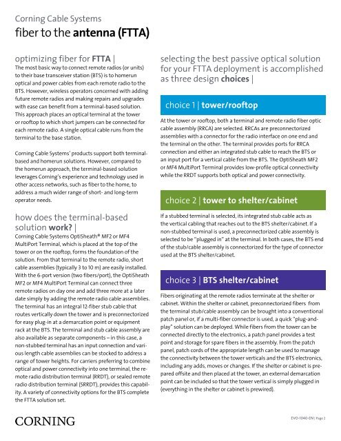
choice 1 | <strong>to</strong>wer/roof<strong>to</strong>p<br />
At <strong>the</strong> <strong>to</strong>wer or roof<strong>to</strong>p, both a terminal and remote radio fiber optic<br />
cable assembly (RRCA) are selected. RRCAs are preconnec<strong>to</strong>rized<br />
assemblies with a connec<strong>to</strong>r for <strong>the</strong> radio interface on one end and<br />
<strong>the</strong> terminal on <strong>the</strong> o<strong>the</strong>r. The terminal provides ports for RRCA<br />
connection and ei<strong>the</strong>r an integrated stub cable <strong>to</strong> reach <strong>the</strong> BTS or<br />
an input port for a vertical cable from <strong>the</strong> BTS. The OptiSheath MF2<br />
or MF4 MultiPort Terminal provides low-profile optical connectivity<br />
while <strong>the</strong> RRDT supports both optical and power connectivity.<br />
choice 2 | <strong>to</strong>wer <strong>to</strong> shelter/cabinet<br />
If a stubbed terminal is selected, its integrated stub cable acts as<br />
<strong>the</strong> vertical cabling that reaches out <strong>to</strong> <strong>the</strong> BTS shelter/cabinet. If a<br />
non-stubbed terminal is used, a preconnec<strong>to</strong>rized cable assembly is<br />
selected <strong>to</strong> be “plugged in” at <strong>the</strong> terminal. In both cases, <strong>the</strong> BTS end<br />
of <strong>the</strong> stub/cable assembly is connec<strong>to</strong>rized for <strong>the</strong> type of connec<strong>to</strong>r<br />
used at <strong>the</strong> BTS shelter/cabinet.<br />
choice 3 | BTS shelter/cabinet<br />
<strong>Fiber</strong>s originating at <strong>the</strong> remote radios terminate at <strong>the</strong> shelter or<br />
cabinet. Within <strong>the</strong> shelter or cabinet, preconnec<strong>to</strong>rized fibers from<br />
<strong>the</strong> terminal stub/cable assembly can be brought in<strong>to</strong> a conventional<br />
patch panel or, if a multi-fiber connec<strong>to</strong>r is used, a quick “plug-andplay”<br />
solution can be deployed. While fibers from <strong>the</strong> <strong>to</strong>wer can be<br />
connected directly <strong>to</strong> <strong>the</strong> electronics, a patch panel provides a test<br />
point and s<strong>to</strong>rage for spare fibers in <strong>the</strong> assembly. From <strong>the</strong> patch<br />
panel, patch cords of <strong>the</strong> appropriate length can be used <strong>to</strong> manage<br />
<strong>the</strong> connectivity between <strong>the</strong> <strong>to</strong>wer verticals and <strong>the</strong> BTS electronics,<br />
including any adds, moves or changes. If <strong>the</strong> shelter or cabinet is prepared<br />
offsite and <strong>the</strong>n placed at <strong>the</strong> <strong>to</strong>wer, an external demarcation<br />
point can be included so that <strong>the</strong> <strong>to</strong>wer vertical is simply plugged in<br />
(everything in <strong>the</strong> shelter or cabinet is prewired).<br />
EVO-1040-EN | Page 2