Fiber to the antenna - Corning Incorporated
Fiber to the antenna - Corning Incorporated
Fiber to the antenna - Corning Incorporated

Create successful ePaper yourself
Turn your PDF publications into a flip-book with our unique Google optimized e-Paper software.
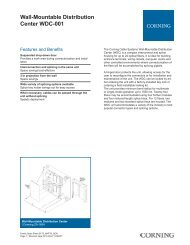
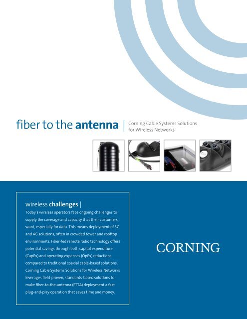
fiber <strong>to</strong> <strong>the</strong> <strong>antenna</strong><br />
wireless challenges |<br />
Today’s wireless opera<strong>to</strong>rs face ongoing challenges <strong>to</strong><br />
supply <strong>the</strong> coverage and capacity that <strong>the</strong>ir cus<strong>to</strong>mers<br />
want, especially for data. This means deployment of 3G<br />
and 4G solutions, often in crowded <strong>to</strong>wer and roof<strong>to</strong>p<br />
environments. <strong>Fiber</strong>-fed remote radio technology offers<br />
potential savings through both capital expenditure<br />
(CapEx) and operating expenses (OpEx) reductions<br />
compared <strong>to</strong> traditional coaxial cable-based solutions.<br />
<strong>Corning</strong> Cable Systems Solutions for Wireless Networks<br />
leverages field-proven, standards-based solutions <strong>to</strong><br />
make fiber-<strong>to</strong>-<strong>the</strong>-<strong>antenna</strong> (FTTA) deployment a fast<br />
plug-and-play operation that saves time and money.<br />
<strong>Corning</strong> Cable Systems Solutions<br />
for Wireless Networks
<strong>Corning</strong> Cable Systems<br />
fiber <strong>to</strong> <strong>the</strong> <strong>antenna</strong> (FTTA)<br />
optimizing fiber for FTTA |<br />
The most basic way <strong>to</strong> connect remote radios (or units)<br />
<strong>to</strong> <strong>the</strong>ir base transceiver station (BTS) is <strong>to</strong> homerun<br />
optical and power cables from each remote radio <strong>to</strong> <strong>the</strong><br />
BTS. However, wireless opera<strong>to</strong>rs concerned with adding<br />
future remote radios and making repairs and upgrades<br />
with ease can benefit from a terminal-based solution.<br />
This approach places an optical terminal at <strong>the</strong> <strong>to</strong>wer<br />
or roof<strong>to</strong>p <strong>to</strong> which short jumpers can be connected for<br />
each remote radio. A single optical cable runs from <strong>the</strong><br />
terminal <strong>to</strong> <strong>the</strong> base station.<br />
<strong>Corning</strong> Cable Systems’ products support both terminalbased<br />
and homerun solutions. However, compared <strong>to</strong><br />
<strong>the</strong> homerun approach, <strong>the</strong> terminal-based solution<br />
leverages <strong>Corning</strong>’s experience and technology used in<br />
o<strong>the</strong>r access networks, such as fiber <strong>to</strong> <strong>the</strong> home, <strong>to</strong><br />
address a much wider range of short- and long-term<br />
opera<strong>to</strong>r needs.<br />
how does <strong>the</strong> terminal-based<br />
solution work? |<br />
<strong>Corning</strong> Cable Systems OptiSheath® MF2 or MF4<br />
MultiPort Terminal, which is placed at <strong>the</strong> <strong>to</strong>p of <strong>the</strong><br />
<strong>to</strong>wer or on <strong>the</strong> roof<strong>to</strong>p, forms <strong>the</strong> foundation of <strong>the</strong><br />
solution. From that terminal <strong>to</strong> <strong>the</strong> remote radio, short<br />
cable assemblies (typically 3 <strong>to</strong> 10 m) are easily installed.<br />
With <strong>the</strong> 6-port version (two fibers/port), <strong>the</strong> OptiSheath<br />
MF2 or MF4 MultiPort Terminal can connect three<br />
remote radios on day one and add three more at a later<br />
date simply by adding <strong>the</strong> remote radio cable assemblies.<br />
The terminal has an integral 12-fiber stub cable that<br />
routes vertically down <strong>the</strong> <strong>to</strong>wer and is preconnec<strong>to</strong>rized<br />
for easy plug-in at a demarcation point or equipment<br />
rack at <strong>the</strong> BTS. The terminal and stub cable assembly are<br />
also available as separate components – in this case, a<br />
non-stubbed terminal has an input connection and various<br />
length cable assemblies can be s<strong>to</strong>cked <strong>to</strong> address a<br />
range of <strong>to</strong>wer heights. For carriers preferring <strong>to</strong> combine<br />
optical and power connectivity in<strong>to</strong> one terminal, <strong>the</strong> remote<br />
radio distribution terminal (RRDT), or sealed remote<br />
radio distribution terminal (SRRDT), provides this capability.<br />
A variety of connectivity options for <strong>the</strong> BTS complete<br />
<strong>the</strong> FTTA solution set.<br />
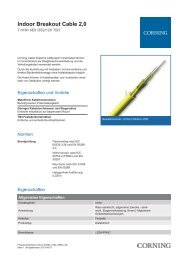
selecting <strong>the</strong> best passive optical solution<br />
for your FTTA deployment is accomplished<br />
as three design choices |<br />
choice 1 | <strong>to</strong>wer/roof<strong>to</strong>p<br />
At <strong>the</strong> <strong>to</strong>wer or roof<strong>to</strong>p, both a terminal and remote radio fiber optic<br />
cable assembly (RRCA) are selected. RRCAs are preconnec<strong>to</strong>rized<br />
assemblies with a connec<strong>to</strong>r for <strong>the</strong> radio interface on one end and<br />
<strong>the</strong> terminal on <strong>the</strong> o<strong>the</strong>r. The terminal provides ports for RRCA<br />
connection and ei<strong>the</strong>r an integrated stub cable <strong>to</strong> reach <strong>the</strong> BTS or<br />
an input port for a vertical cable from <strong>the</strong> BTS. The OptiSheath MF2<br />
or MF4 MultiPort Terminal provides low-profile optical connectivity<br />
while <strong>the</strong> RRDT supports both optical and power connectivity.<br />
choice 2 | <strong>to</strong>wer <strong>to</strong> shelter/cabinet<br />
If a stubbed terminal is selected, its integrated stub cable acts as<br />
<strong>the</strong> vertical cabling that reaches out <strong>to</strong> <strong>the</strong> BTS shelter/cabinet. If a<br />
non-stubbed terminal is used, a preconnec<strong>to</strong>rized cable assembly is<br />
selected <strong>to</strong> be “plugged in” at <strong>the</strong> terminal. In both cases, <strong>the</strong> BTS end<br />
of <strong>the</strong> stub/cable assembly is connec<strong>to</strong>rized for <strong>the</strong> type of connec<strong>to</strong>r<br />
used at <strong>the</strong> BTS shelter/cabinet.<br />
choice 3 | BTS shelter/cabinet<br />
<strong>Fiber</strong>s originating at <strong>the</strong> remote radios terminate at <strong>the</strong> shelter or<br />
cabinet. Within <strong>the</strong> shelter or cabinet, preconnec<strong>to</strong>rized fibers from<br />
<strong>the</strong> terminal stub/cable assembly can be brought in<strong>to</strong> a conventional<br />
patch panel or, if a multi-fiber connec<strong>to</strong>r is used, a quick “plug-andplay”<br />
solution can be deployed. While fibers from <strong>the</strong> <strong>to</strong>wer can be<br />
connected directly <strong>to</strong> <strong>the</strong> electronics, a patch panel provides a test<br />
point and s<strong>to</strong>rage for spare fibers in <strong>the</strong> assembly. From <strong>the</strong> patch<br />
panel, patch cords of <strong>the</strong> appropriate length can be used <strong>to</strong> manage<br />
<strong>the</strong> connectivity between <strong>the</strong> <strong>to</strong>wer verticals and <strong>the</strong> BTS electronics,<br />
including any adds, moves or changes. If <strong>the</strong> shelter or cabinet is prepared<br />
offsite and <strong>the</strong>n placed at <strong>the</strong> <strong>to</strong>wer, an external demarcation<br />
point can be included so that <strong>the</strong> <strong>to</strong>wer vertical is simply plugged in<br />
(everything in <strong>the</strong> shelter or cabinet is prewired).<br />
EVO-1040-EN | Page 2
<strong>Corning</strong> Cable Systems<br />
fiber <strong>to</strong> <strong>the</strong> <strong>antenna</strong> (FTTA)<br />
OptiSheath ®<br />
MF2<br />
MultiPort<br />
Terminal<br />
Solution Set<br />
Remote<br />
Radio<br />
Distribution<br />
Terminal<br />
Solution Set<br />
OptiSheath<br />
MF2 and<br />
MF4 MultiPort<br />
Terminal<br />
with stub<br />
Alternate:<br />
OptiSheath<br />
MF2 and<br />
MF4 MultiPort<br />
Terminal<br />
without stub<br />
Alternate:<br />
Sealed<br />
Remote<br />
Radio<br />
Distribution<br />
Terminal<br />
(SRRDT)<br />
choice 1<br />
choice 1<br />
choice 2<br />
choice 2<br />
choice 3<br />
choice 3<br />
EVO-1040-EN | Page 3
<strong>Corning</strong> Cable Systems<br />
fiber <strong>to</strong> <strong>the</strong> <strong>antenna</strong> (FTTA)<br />
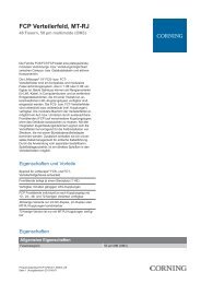
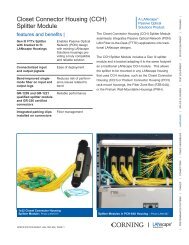
what are <strong>the</strong> components? |<br />
<strong>to</strong>wer/roof<strong>to</strong>p<br />
The OptiSheath® MF2 or MF4<br />
MultiPort Terminal is available in<br />
both stubbed and non-stubbed form,<br />
where <strong>the</strong> non-stubbed terminal<br />
accepts a separate “feeder” cable<br />
assembly. The RRDT, or SRRDT,<br />
allows up <strong>to</strong> 24 fiber connections<br />
(12 remote radios) AND terminal<br />
surge protection for six pairs of<br />
conduc<strong>to</strong>rs (six remote radios).<br />
Stubbed OptiSheath MF2<br />
or MF4 MultiPort Terminal<br />
Remote Radio Distribution<br />
Terminal (RRDT)<br />
Non-Stubbed OptiSheath<br />
MF2 or MF4 MultiPort<br />
Terminal<br />
Remote Radio <strong>Fiber</strong> Optic<br />
Cable Assemblies<br />
Sealed Remote Radio Distribution<br />
Terminal (SRRDT)<br />
EVO-1040-EN | Page 4
<strong>Corning</strong> Cable Systems<br />
fiber <strong>to</strong> <strong>the</strong> <strong>antenna</strong> (FTTA)<br />
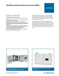
what are <strong>the</strong> components? |<br />
<strong>to</strong>wer <strong>to</strong> shelter<br />
While <strong>the</strong> stubbed MF2 or MF4<br />
terminal has an integrated vertical<br />
cable, both <strong>the</strong> non-stubbed terminal<br />
and <strong>the</strong> RRDT use separate vertical<br />
cable assemblies for design and<br />
deployment flexibility. The MF2 or<br />
MF4 terminal requires an OptiTip®<br />
Connec<strong>to</strong>r as <strong>the</strong> “input” port, while<br />
<strong>the</strong> RRDT uses LC duplex connec<strong>to</strong>rs.<br />
In each case, <strong>the</strong> shelter or cabinet<br />
end of <strong>the</strong> vertical cable can be configured<br />
with a range of connec<strong>to</strong>r types<br />
– OptiTip, MTP®, LC duplex or SC.<br />
OptiTip Connec<strong>to</strong>r<br />
Hybrid Cables<br />
MTP Connec<strong>to</strong>r Duplex LC Connec<strong>to</strong>r<br />
EVO-1040-EN | Page 5
<strong>Corning</strong> Cable Systems<br />
fiber <strong>to</strong> <strong>the</strong> <strong>antenna</strong> (FTTA)<br />
what are <strong>the</strong> components? |<br />
shelter/cabinet<br />
A range of traditional and quickconnection<br />
solutions are available<br />
for <strong>the</strong> shelter or cabinet. Inclusion<br />
of spare fibers as well as <strong>the</strong> potential<br />
for equipment changes makes a<br />
patch panel approach ideal as a test<br />
point and “parking” area for fibers not<br />
yet utilized. An external demarcation<br />
point is used by many opera<strong>to</strong>rs as<br />
a hand-off between prefabricated<br />
and site-built elements as well as<br />
multiple contrac<strong>to</strong>r responsibilities.<br />
OptiTip ® Module Rack-Mount<br />
Housing<br />
Closet Connec<strong>to</strong>r Housing<br />
(CCH-01U) with duplex<br />
connec<strong>to</strong>r panels<br />
Environmental Distribution<br />
Center (EDC) as a demarcation<br />
point<br />
EVO-1040-EN | Page 6
<strong>Corning</strong> Cable Systems<br />
fiber <strong>to</strong> <strong>the</strong> <strong>antenna</strong> (FTTA)<br />
how does <strong>the</strong> value stack up? |<br />
Relative <strong>to</strong> both coaxial cable-based solutions and optical<br />
homerun solutions, <strong>Corning</strong> Cable Systems’ terminalbased<br />
approach can save both money and time:<br />
| Money – Compared <strong>to</strong> coax cable deployments, with 6 <strong>to</strong> 12<br />
coaxial cables, a fiber-fed remote radio solution can save as<br />
much as 50-60% on <strong>to</strong>tal material and installation costs. The<br />
sheer number and length of coaxial cables that must be placed<br />
is a key driving fac<strong>to</strong>r. The higher <strong>the</strong> <strong>to</strong>wer becomes, <strong>the</strong> need<br />
for larger coaxial cable, at higher per foot cost, widens <strong>the</strong> gap.<br />
Compared with <strong>the</strong> homerun solution, <strong>Corning</strong> Cable Systems<br />
OptiSheath® MF2 or MF4 MultiPort Terminal can fur<strong>the</strong>r<br />
reduce costs, saving up <strong>to</strong> 15% on material and installation.<br />
Additional benefits include spare ports, replaceable remote<br />
radio cable assemblies and a single optical sheath down <strong>the</strong><br />
<strong>to</strong>wer (compared <strong>to</strong> three and 12 in <strong>the</strong> homerun scenario).<br />
Reducing <strong>the</strong> number of cables saves time and money during<br />
installation and may reduce monthly lease costs as well.<br />
| Time – A fiber-fed solution installs quickly, getting <strong>the</strong> site<br />
up and running much faster than with a coax solution. Comparing<br />
a site with three <strong>antenna</strong>s and six coax lines <strong>to</strong> a site<br />
with three remote radios/<strong>antenna</strong>s, a four-technician crew would complete<br />
<strong>the</strong> coax <strong>to</strong>wer work in about three days. For a fiber homerun solution,<br />
that drops <strong>to</strong> three technicians and two days. With <strong>Corning</strong> Cable Systems<br />
OptiSheath MF2 or MF4 MultiPort Terminal, <strong>the</strong> three-technician crew can<br />
knock out <strong>the</strong> job in as little as one day. This translates in<strong>to</strong> better productivity<br />
from existing crews and more sites done for <strong>the</strong> same hours spent.<br />
| Weight – Consolidating in<strong>to</strong> a single optical cable reduces weight and can<br />
help avoid costly <strong>to</strong>wer upgrades. For <strong>the</strong> same three <strong>antenna</strong> solutions as<br />
above, <strong>the</strong> fiber solution (with power cable included) can reduce weight load<br />
on <strong>the</strong> <strong>to</strong>wer by as much as 62%.<br />
| Sparing – A <strong>to</strong>wer-<strong>to</strong>p terminal can include spare ports for future remote<br />
radio connection at minimal material and virtually no installation cost.<br />
This avoids <strong>the</strong> need for additional cables that would be required with <strong>the</strong><br />
homerun approach.<br />
| Repair, Maintenance and Testing – With a terminal, <strong>the</strong> radio cable assembly<br />
can be quickly replaced, whereas <strong>the</strong> homerun approach requires a completely<br />
new cable assembly all <strong>the</strong> way down <strong>the</strong> <strong>to</strong>wer.<br />
| Power Costs – Remote radio technology makes more efficient use of utility<br />
power by avoiding <strong>the</strong> typical three dB RF power loss in coax lines and by<br />
lowering <strong>the</strong> HVAC load in <strong>the</strong> shelter.<br />
EVO-1040-EN | Page 7
<strong>Corning</strong> Cable Systems<br />
fiber <strong>to</strong> <strong>the</strong> <strong>antenna</strong> (FTTA)<br />
how do I find out more? |<br />
<strong>Corning</strong> Cable Systems is your tip-<strong>to</strong>-tip fiber optic provider,<br />
with everything needed <strong>to</strong> connect your remote radios <strong>to</strong><br />
your base station. <strong>Corning</strong> also provides technical support<br />
and design assistance for our cus<strong>to</strong>mers. We can assist you<br />
by evaluating your particular application and recommending<br />
a solution geared <strong>to</strong>ward your requirements.<br />
reference literature |<br />
OptiSheath® MF2 or MF4<br />
MultiPort Terminal Literature Code EVO-1135-EN<br />
Remote Radio Distribution Terminal and<br />
Remote Radio <strong>Fiber</strong> Optic Cable Assemblies Literature Code EVO-1056-EN<br />
Sealed Remote Radio<br />
Distribution Terminal (SRRDT) Literature Code CAR-008-EN<br />
Wireless Consolidation Terminal Literature Code EVO-1005-EN<br />
Cell Site Drop Cable Assembly Literature Code EVO-1018-EN<br />
OptiTip® Module Rack- and Literature Code EVO-1090-EN<br />
Wall-Mount Solution<br />
Closet Connec<strong>to</strong>r Housing (CCH) Literacture Code LAN-1129-EN<br />
Please contact your <strong>Corning</strong> Cable Systems Cus<strong>to</strong>mer<br />
Service Representative at 800-743-2671 or visit our Web<br />
site at www.corning.com/cablesystems/wireless<br />
<strong>Corning</strong> Cable Systems LLC<br />
PO Box 489<br />
Hickory NC 28603-0489 USA |<br />
800-743-2675 | Fax: 828-325-5060<br />
International: +1-828-901-5000<br />
www.corning.com/cablesystems<br />
<strong>Corning</strong> Cable Systems reserves <strong>the</strong> right <strong>to</strong> improve, enhance and<br />
modify <strong>the</strong> features and specifications of <strong>Corning</strong> Cable Systems<br />
products without prior notification. OptiSheath and OptiTip<br />
are registered trademarks of <strong>Corning</strong> Cable Systems Brands, Inc.<br />
AnyLAN is a trademark of <strong>Corning</strong> Cable Systems Brands, Inc. MTP is a<br />
registered trademark of USConec, Ltd. <strong>Corning</strong> is a registered trademark<br />
of <strong>Corning</strong> <strong>Incorporated</strong>. All o<strong>the</strong>r trademarks are <strong>the</strong> properties of <strong>the</strong>ir<br />
respective owners. <strong>Corning</strong> Cable Systems is ISO 9001 certified.<br />
© 2011, 2012 <strong>Corning</strong> Cable Systems. All rights reserved. Published<br />
in <strong>the</strong> USA. EVO-1040-EN / April 2012