Fiber Optic Cable Products - LS Cable & System
Fiber Optic Cable Products - LS Cable & System
Fiber Optic Cable Products - LS Cable & System

Create successful ePaper yourself
Turn your PDF publications into a flip-book with our unique Google optimized e-Paper software.
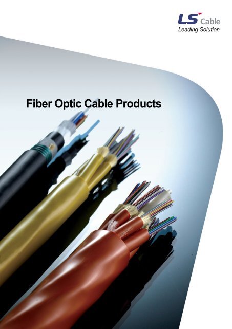
<strong>Fiber</strong> <strong>Optic</strong> <strong>Cable</strong> <strong>Products</strong><br />
Leading Solution
Leading Solution<br />
LG <strong>Cable</strong>, LG Industrial <strong>System</strong>s and LG-Nikko Copper,<br />
Gaon <strong>Cable</strong>, E1 and Yesco are starting with<br />
a new name, Leading Solution, <strong>LS</strong>.
<strong>LS</strong>-<strong>Fiber</strong> <strong>Optic</strong> <strong>Cable</strong> <strong>Products</strong><br />
As a telecommunication cable manufacturer and a division of <strong>LS</strong> <strong>Cable</strong>,<br />
<strong>LS</strong> Data Communication Product and Components never stops<br />
researching, designing, developing, and manufacturing products with the<br />
higher level of quality to address the ever-changing demands in everyday<br />
life as well as in the industry.<br />
Our quality control meets the most delicate requirements of international<br />
standards and the high level of quality is recognized both by local and<br />
international clients.<br />
Our commitment to develop and deliver solutions to address our<br />
customers’ needs and challenges keep our technology on the cutting edge<br />
and our know-how in the field more valuable, which our customers highly<br />
appreciate. We are looking forward to working with you.
Contents<br />
<strong>Fiber</strong>s<br />
Part Number Index<br />
Xwave TM & Xwave-s TM<br />
Zwave TM<br />
DreamLight TM<br />
Multi Mode <strong>Fiber</strong><br />
Giga TM<br />
<strong>Fiber</strong> <strong>Optic</strong> <strong>Cable</strong>s (Indoor)<br />
Part Number Index<br />
All Dielectric Single Jacketed Central Tube<br />
900um 2fiber buffered Aramid yarn strength member<br />
900um tight buffered Glass yarn strength member<br />
900um tight buffered Aramid yarn strength member<br />
ONFR(riser rated), OFNP(plenum rated) or <strong>LS</strong>ZH rated<br />
Micro Distribution <strong>Cable</strong><br />
ONFR(riser rated), OFNP(plenum rated) or <strong>LS</strong>ZH rated<br />
900um tight buffered Aramid yarn strength member Interlocking Armored <strong>Cable</strong><br />
<strong>Fiber</strong> <strong>Optic</strong> <strong>Cable</strong>s (Outdoor)<br />
Part Number Index<br />
Single Jacket Single Armor Central Loose Tube <strong>Cable</strong><br />
All Dielectric Single Jacketed Central Tube with Polyamide coat for Insect-resistant<br />
All Dielectric Single Jacket Non-Armor Loose Tube <strong>Cable</strong><br />
All Dielectric Single Jacketed Multi Loose Tube with Polyamide Sheath for Insect-resistant<br />
Single Jacket Single Armor Loose Tube <strong>Cable</strong><br />
Double Jacket Single Armor Loose Tube <strong>Cable</strong><br />
Single Jacket Non Armor Loose Tube <strong>Cable</strong><br />
Single Jacket Single Armor Loose Tube <strong>Cable</strong><br />
ADSS (Max span: 100m) Aerial <strong>Fiber</strong> <strong>Optic</strong> <strong>Cable</strong><br />
ADSS (Max span: 200m) Aerial <strong>Fiber</strong> <strong>Optic</strong> <strong>Cable</strong><br />
ADSS (Span 400m) Aerial <strong>Fiber</strong> <strong>Optic</strong> <strong>Cable</strong><br />
Single Jacket Single Armor Central Loose Tube <strong>Cable</strong><br />
Single Jacket Single Armor Central Loose Tube <strong>Cable</strong><br />
Single Jacket Non Armor Stranded Ribbon Tube <strong>Cable</strong><br />
Single Jacket Single Armor Stranded Ribbon Tube <strong>Cable</strong><br />
Global Network<br />
7<br />
9<br />
11<br />
13<br />
15<br />
16<br />
21<br />
23<br />
24<br />
25<br />
26<br />
27<br />
28<br />
29<br />
30<br />
31<br />
33<br />
34<br />
35<br />
36<br />
37<br />
38<br />
39<br />
40<br />
41<br />
42<br />
43<br />
44<br />
45<br />
46<br />
47<br />
48
Giga TM<br />
For High Speed Local Network Superior Performance and Reliability !!<br />
The rapid world-wide growth of the internet has prompted the<br />
performance improvement and infrastructure expansion of<br />
fiber optic communication system. The demand for higher<br />
quality and better performance optical communication had led<br />
to the continuous increase of deployment of new high speed<br />
network. Especially, faster access network service is needed<br />
to overcome the bandwidth bottleneck between local access<br />
network and long-haul network.<br />
Fast Ethernet, FDDI, and ATM Protocol are the main<br />
protocols for the indoor and premises network solution, and<br />
Multimode <strong>Fiber</strong> and UTP <strong>Cable</strong> are used as main<br />
transmission media. In general, the transmission speed of<br />
LAN backbone network needs to be 10 times faster than<br />
desktop access line, which necessitates the introduction of<br />
Gigabit Ethernet system that offers high information carrying<br />
capacity. Gigabit Ethernet, being an extended version of<br />
Ethernet system, is preferred as the enterprise LAN and<br />
needs a new transmission media. <strong>LS</strong> <strong>Cable</strong>’s newly<br />
developed Giga is the perfect media for Gigabit Ethernet<br />
system.<br />
SAN<br />
Internet Data Center<br />
Sever<br />
Disk Array<br />
Switch<br />
WAN / MAN<br />
Center/ Office<br />
1Tbit DWDM<br />
Long Haul<br />
Host<br />
Router<br />
Core<br />
Router<br />
Access<br />
Router/<br />
Switch<br />
10 Gbit<br />
10-40 km<br />
Access<br />
Figure 1. <strong>Optic</strong>al <strong>System</strong><br />
LAN<br />
Enterprise<br />
LAN<br />
Backbone<br />
Switch<br />
Sever<br />
<strong>Optic</strong>al <strong>System</strong><br />
With the advent of Gigabit Ethernet <strong>System</strong>s utilizing<br />
multimode fiber, the limiting factor in the fiber backbone was<br />
no longer the attenuation of the passive link, but rather the<br />
information carrying capacity of the fiber. Due to different<br />
signal characteristics of the transmitter, new test procedures<br />
and a new understanding of the interaction between the<br />
optical fiber and the optical signal were required.<br />
Gigabit Ethernet systems are the result of the continual<br />
evolution of networks toward higher and higher speeds. The<br />
incessant demands of end-users to move large amounts of<br />
data at gigabit speeds required a new technology to handle<br />
the 100-fold increase in the transmitting speed used in the<br />
network. To this end, the Institute of Electrical and Electronic<br />
Engineers (IEEE) 802.3z committee revised the Ethernet<br />
protocol standards for transmission for optical networks at<br />
one gigabit. The revised protocol standards are based upon<br />
the Fast Ethernet system protocol developed in 1995. These<br />
new protocols are 1000Base-SX for 850nm wavelength using<br />
laser-based transceivers over multimode optical fiber and<br />
1000Base-LX for 1300nm wavelength using laser-based<br />
transceivers over multimode or singlemode optical fibers,<br />
which are to be considered Gigabit Ethernet (GbE).<br />
10-Gigabit Ethernet (10-GbE) standard considering the trend<br />
toward increasing traffic levels, as well as the development of<br />
more bandwidth-intensive applications, 10-Gbit/sec capability<br />
in both LANs and MANs will become extremely important. 10-<br />
GbE is the first Ethernet standard that will only function over<br />
optical fiber. Operation is over full-duplex mode and only with<br />
point-to-point connections, so collision detection protocols are<br />
not required.<br />
The key criteria for efficient and effective high-speed<br />
networks are as follow.<br />
- Easy, straightforward migration to higher performance<br />
levels without disruption<br />
- Low cost of ownership<br />
- Familiar management tools and common skills base<br />
- Flexibility in network design<br />
TIA FO2.2.1 Working Group has been determining the<br />
necessary performance criteria for multimode fiber (MMF)<br />
and 850-nm laser transmitters to support emerging 10-<br />
Gbit/sec applications to at least 300 m. The effort succeeded<br />
in providing a low-cost solution meeting the distance<br />
requirements of the vast majority of in-building LANs, storagearea<br />
networks (SANs), and equipment room inter<br />
connections using 850-nm vertical-cavity surface-emitting<br />
laser (VCSEL) serial transceivers and laser-optimized 50micron<br />
MMF.<br />
Laser Sources & Gigabit MMF<br />
The light source for Gigabit Ethernet system needs to be<br />
cost-effective for data transmission speed and installation.<br />
The typical light sources that satisfy these requirements are<br />
VCSEL and low cost FP-LD. Besides the operating<br />
bandwidth, another difference between LED and LD is beam<br />
pattern. The different operating patterns of multimode fiber<br />
using different light sources are shown in figure 2.<br />
IP1050 I Issued: May 2007 I ISO 9001 REGISTERED 16
Giga TM<br />
For High Speed Local Network Superior Performance and Reliability !!<br />
Laser<br />
LED<br />
<strong>Fiber</strong> Core<br />
<strong>Fiber</strong> Core<br />
Figure 2. The operation pattern of<br />
Multimode <strong>Fiber</strong> by light source<br />
<strong>Fiber</strong> Cladding<br />
<strong>Fiber</strong> Cladding<br />
LED has 100ß≠ beam size and excites entire core of<br />
multimode fiber. On the contrary, FP-LD or VCSEL have<br />
relatively smaller beam size than fiber core and the light is<br />
launched into the partial core of multimode fiber exciting few<br />
modes. These different launching conditions induce different<br />
transmission characteristics for the same multimode fiber. As<br />
a result, transmission capacity of multimode fiber varies with<br />
laser source type, therefore this variation results in the<br />
modification of the definition of bandwidth. Bandwidth was<br />
originally defined under the condition of all modes exciting in<br />
core using LED, called Over Filled Launching(OFL).<br />
However, OFL bandwidth is not a good indicator under the<br />
condition of few modes exciting in core using LD. This few<br />
mode exciting condition is redefined as laser-based<br />
bandwidth and specified in TIA/EIA FOTP-204 which is<br />
redefinition of FOTP-30 and FOTP-51.<br />
For the enhancement of transmission performance of MMF,<br />
core index profile must be carefully controlled. Defects of<br />
refractive index profile affects the transmission quality of<br />
multimode fiber for Gigabit Ethernet system. Among these<br />
defects, index dip is the major factor that impairs the<br />
performance of multimode fiber. Index dip originates from the<br />
evaporation of volatile dopants in the MCVD process.<br />
Because gigabit transmission system uses LD instead of<br />
LED, core central defect, like index dip, must be eliminated.<br />
The elimination of refractive index dip can be achieved<br />
through the fine control of manufacturing process. Even in the<br />
absent of core center dip, finite tuning is also important factor<br />
for transmission performance.<br />
<strong>LS</strong> <strong>Cable</strong> developed center dip free process and realized<br />
uniform index profile. Fig. 3-(a) shows the typical index profile<br />
of conventional multimode fiber and Fig.3-(b) shows index<br />
profile of newly developed multimode fiber.<br />
17 IP1050 I Issued: May 2007 I ISO 9001 REGISTERED<br />
Center Dip<br />
Laser Launching Region<br />
Laser Launching Region<br />
Figure 3. Index Profile of Multimode <strong>Fiber</strong><br />
Conventional and Laser optimized MMF<br />
TIA FO2.2.1 Working Group, which determined the<br />
performance requirements and accompanying new test<br />
procedure to measure the differential mode delay (DMD)<br />
property of the new fiber. The Telecommunications Industry<br />
Association (TIA) published the test procedure, FOTP-<br />
220.The ballot on a detailed fiber specification, to be<br />
published as TIA/EIA-492AAAC.<br />
Figure 4. DMD Measurement scheme<br />
Perturbations in the index profile capable of affecting the laser<br />
bandwidth can appear as negligible differences from the<br />
power-law profile using even the most sensitive index-profile<br />
measurement techniques. Fortunately, fiber-profile quality<br />
can be controlled and quantified using a technique called<br />
differential mode delay (DMD, FOTP-220), which measures<br />
the delay of each mode by scanning across the fiber core<br />
with a small launch spot. The DMD curve in Figure 4<br />
illustrates the typical effect of an index depression at the<br />
center of the core. The delay of the lower-order modes<br />
(transmitted on or near the axis of the fiber) is affected<br />
significantly due to this perturbation. The information from the<br />
DMD scan can be used to make minute adjustments to the
index profile to equalize or flatten the DMD profile across the<br />
core of the fiber. It is critical point for system design to<br />
understand.<br />
Figure 5 describes the inter-relationship between<br />
transmission capacity, OFL Bandwidth, RMLB(Retricted<br />
Modal Bandwidth), EMB(Effective Modal Bandwidth) and<br />
DMD. EMB is extended definition of RML Bandwidth. TIA FO-<br />
2.2.1 confirmed its specifications by measuring system EMB,<br />
the information-carrying capacity of a system, taking into<br />
account both fiber modal delays and transmitter launch<br />
condition. EMB measures the effects of multimode-fiber and<br />
transceiver interaction to accurately evaluate overall system<br />
performance.<br />
Guarantee the Performance of Giga TM for<br />
1Gigabit & 10Gigabit Ethernet system<br />
IEEE 802.3z defines the system specification for Gigabit<br />
Ethernet under worst-case philosophy. Under this<br />
configuration, the transmission performance of multimode<br />
fiber can be newly defined. The Gigabit Ethernet <strong>Optic</strong>al Link<br />
Model is used to qualify the transmission performance.<br />
Figure 5. <strong>Optic</strong>al characteristics of multimode fiber<br />
and inter-relationship<br />
This model is based on the concept of power budgeting. The<br />
GbE link model was created by using worst-case models and<br />
applied empirically to <strong>LS</strong> product. The transmission<br />
performance test is conducted following IEEE802.3z. And the<br />
reliability of test result is enhanced with the aid of fiber<br />
shaker(FOTP-142) to simulate worst-case environment.<br />
Figure 6 shows the basic concept of transmission<br />
experiment.<br />
Figure 6. Transmission Measuring Equipment<br />
(According to IEEE802.3z & IEEE802.3ae)<br />
<strong>LS</strong> <strong>Cable</strong> established the test-bed to measure transmission<br />
properties of multimode fiber satisfying international<br />
standards and set up mass production line which can<br />
guarantee the excellent minimum transmission distance of<br />
the fiber.<br />
Figure 7. Measured power penalty dependence<br />
of EMB. For 1GbE Giga TM 62.5(62.5E) series<br />
MMF of 600meterswith different EMB bandwidth<br />
(267, 462, 690MHhz.km),the power penalty varies<br />
from 1dB to 4dB. (Receiver Sensitivity : -19.5dBm)<br />
However, this direct test method is not easily implemented for<br />
mass production process. Therefore, some alternatives are<br />
needed. EMB & DMD are known to have close relationship<br />
with transmission capacity of multimode fiber, and can be<br />
referenced as representative characteristics for 1Gigabit & 10<br />
Gigabit transmission performance. EMB is calculated with<br />
DMD characteristics for various commercially available GbE<br />
transmitters.<br />
IP1050 I Issued: May 2007 I ISO 9001 REGISTERED 18
Giga TM<br />
For High Speed Local Network Superior Performance and Reliability !!<br />
Figure 8. Power Penalty vs. EMB<br />
Figure 7 and 8 show the results of 1GbE transmission<br />
experiment for GigaTM 62.5(62.5E) products.<br />
As shown in figure 8, the test results coincide with IEEE<br />
power penalty link model.<br />
For the application of MMF to short reach 10GbE system,<br />
DMD profile should be finely controlled. TIA/EIA-492AAAC<br />
defines the DMD characteristics of 10Gbps MMF with six<br />
templates of DMD mask. The fiber shall meet at least one of<br />
following six DMD templates, which each consists of both an<br />
inner and outer mask definition.<br />
Figure 9. DMD Mask set defined on<br />
TIA/EIA-492AAAC and typical DMD<br />
profile of Enhanced MMF, Giga TM 50XE<br />
19 IP1050 I Issued: May 2007 I ISO 9001 REGISTERED<br />
To meet the DMD Mask requirements, <strong>LS</strong>C’s GigaTM 50XE is<br />
manufactured carefully for 10GbE application. Figure 9<br />
shows typical DMD characteristics of GigaTM 50XE.<br />
With enhanced DMD characteristics, the transmission<br />
performance of Giga TM 50XE exceeds the IEEE<br />
recommendation.<br />
(A) (B)<br />
Figure 10. Transmitted eye diagram of (a)<br />
150meters of conventional MMF and (b)<br />
700meters of Giga TM 50XE<br />
Giga TM<br />
Giga TM provides gigabit multimode fiber as the solution for<br />
emerging high speed local area network.<br />
The superior performance of Giga TM surpasses the minimum<br />
requirements specified by IEEE802.3z and enhances your<br />
system performance with reliability.<br />
Giga TM supports current indoor and premises network with<br />
superior performance up to 2,000m transmission length.<br />
GigaTM 62.5E guarantees the minimum transmission length of<br />
500m for 850nm and 1000m for 1300nm. Giga TM 50E<br />
guarantees 600m for 850nm and 2000m for 1300nm.<br />
Giga TM 50XE is optimized for 10GbE and Fibre Channel<br />
applications. The safe transmission length exceeds 300m for<br />
the system compatible with 10Gbase-SW/SR.<br />
GigaTM series products of high performance and<br />
reliability are the best solutions for your system.
The Global Network of <strong>LS</strong> <strong>Cable</strong><br />
reaching all over the world<br />
<strong>LS</strong> <strong>Cable</strong> compete with global top corporations with high profit value<br />
products and doing area marketing to create distinctive market value.<br />
Leading Solution