80 Watt KU Band BUC Manual - NEW ERA SYSTEMS INC.
80 Watt KU Band BUC Manual - NEW ERA SYSTEMS INC.
80 Watt KU Band BUC Manual - NEW ERA SYSTEMS INC.

You also want an ePaper? Increase the reach of your titles
YUMPU automatically turns print PDFs into web optimized ePapers that Google loves.
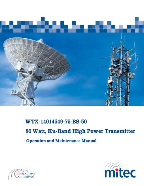
WTX-14014549-75-ES-50<br />
<strong>80</strong> <strong>Watt</strong>, Ku-<strong>Band</strong> High Power Transmitter<br />
Operation and Maintenance <strong>Manual</strong>
This page has been intentionally left blank.
Mitec Telecom inc.<br />
Designers and manufacturers of telecom and wireless products<br />
9000 Trans Canada,<br />
Pointe-Claire, Quebec, Canada<br />
H9R 5Z8<br />
OP<strong>ERA</strong>TION AND MAINTENANCE MANUAL Preliminary Released<br />
REVISION RECORD<br />
Revision ECN # Description Date Approved<br />
1 Engineering Release. 14 Mar 06<br />
CM Approval TITLE:<br />
WTX-14014549-75-ES-50 <strong>80</strong> <strong>Watt</strong>,<br />
14.0-14.5 GHz High Power<br />
Transmitter Module<br />
This document contains information proprietary to mitec telecom inc., or its affiliates, or to a third party to which mitec telecom inc. may have a legal obligation to protect<br />
such information from unauthorized disclosure, use, or duplication. Any disclosure, use, or duplication of this document or of any of the information contained herein is<br />
expressly prohibited except as mitec telecom inc. may otherwise agree in writing.<br />
Designer: G. Cyr Date: 14 Mar 06<br />
Technical Writer: C. Strunga Date: 14 Mar 06<br />
DOCUMENT NO.<br />
211406MA<br />
REV 1<br />
PAGE 1 OF 37
mitec Preface<br />
Scope<br />
Preface<br />
This document covers the installation, operation, and maintenance of the WTX-14014549-75-ES-<br />
50 <strong>80</strong> <strong>Watt</strong>, 14.0-14.5 GHz High Power Transmitter Module. It contains information intended for<br />
engineers, technicians and operators working with the transmitter module.<br />
To make inquiries, or to report errors of fact or omission in this document, please contact Mitec<br />
Telecom inc. at (514) 694-9000.<br />
IMPORTANT<br />
Important information concerning the operation and care of this product, as well as safety of<br />
authorized operators is highlighted throughout this document by one of the following labels:<br />
NOTE<br />
Indicates a reminder, a special consideration, or additional<br />
information that is important to know.<br />
CAUTION!<br />
Identifies situations that have the potential to cause equipment<br />
damage.<br />
WARNING!!<br />
Identifies hazardous situations that have the potential to cause<br />
equipment damage as well as serious personal injury.<br />
Rev 1 P-1
This page has been intentionally left blank.
This page has been intentionally left blank.
mitec Table of Contents<br />
Rev 1<br />
Table of Contents<br />
1 INTRODUCTION ........................................................................... 1<br />
1.1 Receiving and Inspection .........................................................................................2<br />
1.1.1 Equipment Damage or Loss .............................................................................2<br />
1.1.2 Return of Equipment ........................................................................................2<br />
1.2 Preparing for Installation........................................................................................3<br />
1.3 Safety Precautions ....................................................................................................3<br />
2 INSTALLATION & OVERVIEW .................................................. 5<br />
2.1 General Description .................................................................................................5<br />
2.2 Specifications ............................................................................................................5<br />
2.3 General Considerations ...........................................................................................7<br />
2.4 Basic Mechanical Characteristics ...........................................................................7<br />
2.4.1 External View of the Transmitter Module........................................................7<br />
2.4.2 Connections and Mounting Hardware..............................................................8<br />
2.5 Assembly and Installation........................................................................................8<br />
2.5.1 Lifting the Transmitter Module into Position and Temporary Attachment .....8<br />
2.5.2 Securing the Transmitter Module.....................................................................8<br />
2.6 Functional Overview ................................................................................................9<br />
2.6.1 General .............................................................................................................9<br />
2.6.2 IF/RF Conversion and Amplification.............................................................10<br />
2.6.3 Monitor and Control.......................................................................................10<br />
2.6.4 Internal Power Distribution Reference...........................................................11<br />
3 OP<strong>ERA</strong>TION ............................................................................... 13<br />
3.1 Procedure ................................................................................................................13<br />
3.1.1 Interface..........................................................................................................14<br />
4 MAINTENANCE .......................................................................... 15<br />
i
Table of Contents mitec<br />
4.1 Preventive Maintenance.........................................................................................15<br />
4.1.1 Procedure........................................................................................................15<br />
4.1.2 Transmitter Module Cooling System Preventive Maintenance......................15<br />
4.1.3 Performance Check.........................................................................................16<br />
4.1.4 Troubleshooting..............................................................................................16<br />
4.1.5 Out-of Warranty Repair..................................................................................17<br />
APPENDIX A ........................................................................................<br />
Drawings & Schematic Diagrams ............................................................................ A-1<br />
APPENDIX B ........................................................................................<br />
Serial Protocol.............................................................................................................B-1<br />
APPENDIX C ........................................................................................<br />
Spare Parts ................................................................................................................. C-1<br />
APPENDIX D ........................................................................................<br />
Bench Test Record..................................................................................................... D-1<br />
List of Tables<br />
Table 1 –Specifications........................................................................................................5<br />
Table 2 –Connector Pin Assignments................................................................................14<br />
Table 3 - Recommended Corrective Actions.....................................................................16<br />
List of Figures<br />
Figure 1 – Recommended Distance for Mounting on the Hub............................................9<br />
Figure 2 - System Block Diagram .....................................................................................10<br />
Figure 3 – Outline Drawing ............................................................................................ A-3<br />
ii Rev 1
mitec Introduction<br />
1 Introduction<br />
The WTX-14014549-75-ES-50 High Power Transmitter module is a highly reliable, high quality,<br />
cost efficient <strong>80</strong>W L-<strong>Band</strong> to Ku-<strong>Band</strong> High Power Up-Converter System designed for use in<br />
VSAT applications. This line of superior products, engineered using state of the art technology,<br />
is characterized by unparalleled durability and dependability. The system also has high linearity<br />
over the full operating temperature range. The output operating frequency range is the standard<br />
Ku-<strong>Band</strong> of 14.0 to 14.5 GHz.<br />
Rev 1 Page 1
Introduction mitec<br />
1.1 Receiving and Inspection<br />
The transmitter module is designed to function outdoors and will arrive in a standard shipping<br />
container. Immediately upon receipt of the transmitter module, check the Bill of Lading against<br />
the actual equipment you have received. Inspect the shipping containers exteriors for visible<br />
damage incurred during shipping.<br />
CAUTION!<br />
Handle the transmitter module with extreme care. Excessive shock<br />
may damage transmitter module’s delicate internal components.<br />
NOTE<br />
Before unpacking the shipping containers, move them near to the<br />
site where the system will be mounted. Ensure that the<br />
containers are oriented correctly in accordance with the “This<br />
Side UP ”labels. Carefully remove the transmitter module and<br />
packing material from the shipping containers.<br />
Using the supplied packing list, verify that all items have been received and undamaged during<br />
shipment. Verify that all items are complete. If there are any omissions or evidence of improper<br />
packaging, please notify Mitec Telecom inc. immediately.<br />
1.1.1 Equipment Damage or Loss<br />
Mitec Telecom Inc. is not responsible for damage or loss of equipment during transit. For<br />
further information, contact the responsible transport carrier.<br />
When declaring equipment as damaged during transit, preserve the original shipping cartons to<br />
facilitate inspection reporting.<br />
1.1.2 Return of Equipment<br />
When returning equipment to Mitec for repair or replacement:<br />
1. Identify, in writing, the condition of the equipment,<br />
2. Refer to the sales order, Purchase Order and the date the equipment was received.<br />
Notify Mitec Sales Administration Department of the equipment condition and obtain a Return<br />
Material Authorization (RMA) number and shipping instructions. Mitec will pay for the cost of<br />
shipping the product to the customer after the repairs are completed.<br />
Page 2 Rev 1
mitec Introduction<br />
1.2 Preparing for Installation<br />
NOTE<br />
Do not return any equipment without an RMA number. This is<br />
important for prompt, efficient handling of the returned<br />
equipment and of the associated complaint.<br />
Before attempting to install or use the transmitter module, we recommend that you first<br />
familiarize yourself with the product by reading through this manual. Understanding the<br />
operation of the system will reduce the possibility of incorrect installation, thereby causing<br />
damage or injury to yourself or others.<br />
The transmitter module must be installed in accordance with the<br />
conditions and recommendations contained in the following<br />
sections.<br />
When you are ready to begin your installation, use the information in Chapter 2 (Installation) as a<br />
guide for making all the required electrical connections.<br />
1.3 Safety Precautions<br />
Carelessness or mishandling of the transmitter module may damage the unit causing serious<br />
injury to yourself or others. Please adhere to the following:<br />
WARNING!!<br />
This unit is equipped with an AC power cord and plug. Do not<br />
tamper with, or attempt to reconfigure, the cord or plug supplied<br />
with the unit, as this can:<br />
♦ result in personal injury<br />
♦ void the warranty<br />
♦ cause damage to the units or related equipment.<br />
Rev 1 Page 3
This page has been intentionally left blank.
mitec Installation & Overview<br />
2.1 General Description<br />
2.2 Specifications<br />
2 Installation & Overview<br />
This section describes the installation and theory of operation of the transmitter module.<br />
The module is a stand-alone Transmitter System powered from 24 VDC and 190-260 VAC power<br />
sources. It will amplify an input signal from an L-<strong>Band</strong> RF source up to a power level of <strong>80</strong><br />
<strong>Watt</strong>s CW in Ku-<strong>Band</strong>.<br />
The Transmitter consists of a low power block up-converter (<strong>BUC</strong>) and a high power amplifier<br />
(SSPA.)<br />
The SSPA consists of a Power Supply, RF Amplifier, Control System and Cooling System. The<br />
power supply provides DC voltages to the RF amplifier. The RF amplifier is capable of<br />
providing an output level of <strong>80</strong>W, and contains over temperature shut down and protection<br />
circuits. The control system provides telemetry for the RF amplifier via an RS-485 serial<br />
interface. The cooling system fan and heat sink fins together supply and distribute a steady flow<br />
of air, preventing the internal electrical components of the SSPA from over-heating. All three<br />
components are protected by a shroud, which can be removed easily when replacing the cooling<br />
system fan. (Refer to Chapter 4). The SSPA is for outdoor use and is secured onto a mounting<br />
frame by two brackets.<br />
Table 1 summarizes the specifications of the WTX-14014549-75-ES-50 <strong>80</strong> <strong>Watt</strong>, 14.0-14.5 GHz<br />
High Power Transmitter Module. For mechanical specifications, refer to the outline drawing,<br />
Figure 3 in Appendix A.<br />
Table 1 –Specifications<br />
RF Performance<br />
Output Frequency 14.0 to 14.5 GHz<br />
IF Frequency 950 to 1450 MHz<br />
LO Frequency 13.05 GHz<br />
Reference Frequency 10 MHz External Reference;<br />
(0 ± 5) dBm Input Power Level<br />
Small Signal Gain 75 dB, min over temperature<br />
Gain Flatness (small signal) ± 2.5 dB, nominal at 10 dB back-off<br />
Gain Stability with power (expansion) 0.5 dB, max.<br />
Output Power @ 25 0 C 49 dBm (<strong>80</strong> W), min at P1dB<br />
Saturated Output Power 50 dBm, nominal<br />
3 rd Order Intermodulation each -26 dBc max., two equal signals at 43dBm/tone,<br />
Rev 1 Page 5
Installation & Overview mitec<br />
Phase Noise<br />
5 MHz separation<br />
-60 dBc/Hz, max. @300 Hz offset of the carrier<br />
-70 dBc/Hz, max. @ 1 kHz offset of the carrier<br />
-<strong>80</strong> dBc/Hz, max. @ 10 kHz offset of the carrier<br />
-90 dBc/Hz, max. @ 100 kHz offset of the carrier<br />
-100 dBc/Hz, max.@ 1 MHz offset of the carrier<br />
Integrated Phase Noise Error 2.2 degrees, max., form 300 Hz to 1 MHz SSB<br />
Source & Load VSWR 1.5:1 max (operational), infinite at any angle without<br />
damage, unconditionally stable<br />
Input Return Loss (cold) -14 typ.<br />
Output Return Loss -18 dB<br />
Spurious In-band -50 dBc, max @ P1dB<br />
Spurious Out of <strong>Band</strong> -50 dBc, max @ P1dB<br />
Harmonics N/A<br />
RF Monitor Port (optional) POUT -45 dBc, typical<br />
Power Consumption<br />
Controls<br />
1000 W typical<br />
Gain N/A<br />
Mute S/W Via RS-485<br />
Mute H/W Short pin K with Pin M (M&C) connector<br />
Over Temperature Shutdown (82 –2/+3) 0 Indicators<br />
C. at case temperature, internally set<br />
RF Forward Power Via RS-485<br />
RF Overdrive N/A<br />
Over Temperature Via RS-485<br />
Alarm Summary S/W Via RS-485<br />
Alarm Summary H/W TTL Low - Alarm State<br />
Contact closure (Pin E opens from Pin H on alarm)<br />
Temperature Sensor Via RS-485<br />
LED Green (operational) / Red (alarm)/Orange (muted)<br />
Power Supply<br />
Input 190-260 VAC, 50/60 Hz (1,000W)<br />
Power Factor correction 95%<br />
Output 12 VDC, 3.5 A<br />
Efficiency 85% nominal<br />
Design Technology High frequency switching modules<br />
Mechanical Specifications<br />
Package Outdoor, weather resistant<br />
Size (overall dimensions 16.3”x 11.4”x 9.2”<br />
Weight 54 lb (24.5 Kg)<br />
Cooling Forced Air<br />
Exterior Surface Finish Painted white<br />
Hardware Stainless Steel<br />
O-ring Silicone<br />
Page 6 Rev 1
mitec Installation & Overview<br />
Connectors<br />
IF Input N-type female<br />
RF Output WR75 grooved<br />
RF Monitor Type-N, female<br />
AC Power MS3102R16-10P<br />
RS-485 M&C MS3102R20-29S<br />
Markings Labels permanent and legible<br />
1 Mitec Name, Part No & Revision Level<br />
2 Serial No.<br />
3 IF Input<br />
4 RF Output<br />
5 AC power 220AC only<br />
6 RS-485<br />
7 RF Sample<br />
Environmental Operational Storage<br />
Temperature -40 0 to 60 0 C -50 0 C to 85 0 C<br />
Humidity 5% to 95% at -40 0 C 5% to 95% at 65 0 C<br />
Altitude 10,000 ft AMSL 40,000 ft AMSL<br />
Shock and Vibration Normal transport and handling<br />
Wind 100 km/hr N/A<br />
Drop N/A 1m in shipping container<br />
Reliability<br />
MTBF (mean time between failures <strong>80</strong>,000 hours (fan reliability data is not included.<br />
Fan must be replaced once every 2 years minimum.<br />
2.3 General Considerations<br />
The module shall meet all specifications over full bandwidth and under all environmental<br />
conditions when terminated with a load of VSWR at 1.5:1 unless otherwise specified. All RF<br />
specifications shall be met within five minutes after applying DC power, except gain stability,<br />
which shall be met after a warm-up period of twenty minutes. During the warm-up period, the<br />
module shall not exhibit any alarm or require an RF mute input signal to reset any alarm/fault<br />
latches.<br />
2.4 Basic Mechanical Characteristics<br />
2.4.1 External View of the Transmitter Module<br />
The physical external dimensions of the transmitter module are shown in Figure 3 and Table 1.<br />
All inputs and outputs are shown in Figure 3.<br />
Rev 1 Page 7
Installation & Overview mitec<br />
2.4.2 Connections and Mounting Hardware<br />
The IF input connection requires a coaxial cable with an N-type male connector for the RF Input.<br />
The RF output requires a waveguide with a WR75 flat flange. An O-ring shall be used to seal the<br />
waveguide connection. There are also two cylindrical connectors on the RF Input side of the RF<br />
amplifier for AC power and M&C interface. The pin assignments for these connectors are shown<br />
in section 3.1.3. Six screws (#1/4) and two brackets fasten the transmitter onto the mounting<br />
frame. See Figure 3 in Appendix A. Four cap screws (#6-32) and their respective lock washers<br />
fasten the antenna waveguide feeder on to the transmitter waveguide output flange. The mating<br />
connectors, hardware and O-ring are in the shipping container with the transmitter.<br />
2.5 Assembly and Installation<br />
Use the information in this section as a guide to assemble and install the transmitter module. The<br />
specified humidity is up to 100% during operation. However, installation should be carried out in<br />
dry conditions, free of salt spray or excessive humidity. This will eliminate the possibility of<br />
moisture and other foreign substances from entering the output waveguide flange.<br />
CAUTION!<br />
Only authorized technical personnel should perform the<br />
Installation and proper electrical hookups of the transmitter<br />
module.<br />
2.5.1 Lifting the Transmitter Module into Position and Temporary Attachment<br />
The transmitter module weighs approximately 25kg (55 lb), which should be handled by two<br />
persons. Remove all plastic caps from the connectors and output waveguide flange. Lift the<br />
transmitter module and install it on to the mounting frame opening. The transmitter module is<br />
now ready for permanent attachment.<br />
The transmitter is designed to operate in an outdoor environment and is waterproof when<br />
mounted in the correct orientation as per Figure 1 and the orientation labels placed on the RF<br />
amplifier shroud.<br />
The transmitter contains a high flow-rate fan (600 CFM) for cooling the RF amplifier module.<br />
This fan functions continuously during the transmitter operation. To provide a sufficient airflow,<br />
the transmitter should be mounted with a minimum clearance of 5 inches on all four sides and<br />
the bottom. Refer to Figure 1. Adequate cooling for the transmitter will provide years of top<br />
performance.<br />
2.5.2 Securing the Transmitter Module<br />
Secure the transmitter module onto the mounting frame using the hardware described in section<br />
2.3.2. Align the transmitter output waveguide flange with the mating flange of the antenna feeder<br />
waveguide. Using the O-ring and hardware provided connect the antenna feeder waveguide.<br />
Torque the flange screws to 16 inch-pounds (1.8 N-m). Attach the proper cables for waveguide<br />
for IF input, AC power and M&C to the corresponding connectors of the transmitter module.<br />
Refer to Figure 3 in Appendix A.<br />
Page 8 Rev 1
5<br />
mitec Installation & Overview<br />
2.6 Functional Overview<br />
2.6.1 General<br />
NOTE<br />
The cylindrical connectors are labeled clearly and have different<br />
pin layouts. Refer to Figure 3. It is impossible to incorrectly<br />
install the mating connectors.<br />
Figure 1 – Recommended Distance for Mounting on the Hub<br />
This section describes the transmitter module functions in detail. The functional overview<br />
explains the RF amplification, monitor & control and power distribution.<br />
Figure 2 block diagram illustrates the transmitter module.<br />
Rev 1 Page 9<br />
5<br />
5
Installation & Overview mitec<br />
IF In<br />
L-<strong>Band</strong> &<br />
10MHz reference<br />
(0 +/- 5 dBm)<br />
with 24VDC<br />
AC Power IN<br />
190-260 VAC<br />
1,000 W<br />
<strong>BUC</strong> &<br />
SSPA<br />
2.6.2 IF/RF Conversion and Amplification<br />
12 VDC<br />
<strong>80</strong> A max<br />
Power Supply<br />
RS-485<br />
12V DC<br />
Alarm<br />
Figure 2 - System Block Diagram<br />
RF Out<br />
49 dBm min @ P1dB<br />
14.0-14.5 GHz<br />
Cooling System Fan<br />
600 CFM<br />
The IF Input signal with a 10MHz reference, 0-/+5dBm and 24VDC, 1.0A nominal enters the<br />
<strong>BUC</strong> by a coaxial cable, converted to Ku-<strong>Band</strong> by the <strong>BUC</strong> and goes through an isolator, which<br />
provides a good VSWR at the input. Under normal operation, the RF amplifier will amplify the<br />
RF Input signal level up to a power level of 49 dBm (<strong>80</strong> <strong>Watt</strong>s CW) P1dB minimum. For small<br />
signal gain, the transmitter module is capable of providing a gain of approximately 75 dB.<br />
To achieve the rated output power, GaAs transistors, as well as other microwave components<br />
within the RF Amplifier, provide the necessary gain and low insertion loss. The amplified signal<br />
is transmitted through the output waveguide section to a satellite up-link system.<br />
2.6.3 Monitor and Control<br />
The transmitter has an RS-485 serial interface. The transmitter can communicate to the indoor<br />
unit or redundancy control module via RS-485. (For RS-485 Protocol Specifications, see<br />
Appendix B)<br />
The control system can provide the following M&C functions:<br />
� System Alarm: when an amplifier is not functioning properly, TTL logic will activate an<br />
alarm (TTL low: alarm state). The alarm signal will be transmitted via RS-485 as well as<br />
through two analogue wires in order to support the redundancy option.<br />
� Mute Control (via RS-485)<br />
� Mute Control (via hardware line): Short pin K with Pin M (M&C connector)<br />
� Output Power Monitoring: 15 dB dynamic range (via RS-485)<br />
Page 10 Rev 1
mitec Installation & Overview<br />
� Base Plate Temperature Monitoring (via RS-485)<br />
The SSPA can also provide 12VDC (3.5A max) at the same connector to supply DC power for<br />
redundancy control.<br />
2.6.4 Internal Power Distribution Reference<br />
The SSPA operates from power source of 190 VAC to 260 VAC, 50 Hz to 60 Hz and will<br />
consume 1,000-<strong>Watt</strong>s maximum.<br />
CAUTION!<br />
There is an internal slow blowing fuse installed in the power<br />
supply module in order to protect the entire system from over<br />
current.<br />
This unit is not intended to work with 110 volts. Do not attempt<br />
to use at this voltage. Damage to the unit will occur.<br />
The power supply converts the incoming AC voltage into two separate DC voltages. The DC<br />
voltages are regulated to ensure isolation and stability. The module provides:<br />
� 12 VDC, <strong>80</strong> A maximum to the RF amplifier circuits<br />
Rev 1 Page 11
This page has been intentionally left blank.
mitec Maintenance<br />
3.1 Procedure<br />
3 Operation<br />
This chapter describes the verification of the operation and control of the transmitter module. It<br />
shall be performed by authorized personnel prior to maintenance and/or repair.<br />
Verify that the installation procedure described in Chapter 2 was completed. A complete physical<br />
check of the customer’s system is suggested.<br />
WARNING!<br />
The output power available at the output waveguide flange is<br />
extremely hazardous. Under no circumstances should be<br />
transmitter be operated without the waveguide feed or a high<br />
power load attached. Do not operate this equipment in the<br />
presence of flammable gases or fumes. Failure to observe this<br />
precaution will result in personal injury. Safe and careful<br />
installation of this transmitter will eliminate the possibility of<br />
accidents and provide years of top performance.<br />
Verify the antenna feed waveguide connection is properly done before the transmitter is<br />
energized.<br />
NOTE<br />
The transmitter module can withstand any source or load VSWR.<br />
However, the transmitter module will meet all specification<br />
requirements only if the source/load VSWR is sufficient (see<br />
Section 7.1.20).<br />
Normal operation is not possible if the antenna feeder VSWR is<br />
greater than 1.5:1.<br />
Turn ON the power and allow a warm up period of twenty minutes before operating the<br />
transmitter module. This will assure stable gain and power. The transmitter module can function<br />
with a coupler when a direct measurement of the output power is made.<br />
Rev 1 Page 13
Maintenance mitec<br />
CAUTION!<br />
It is strongly recommended not to exceed -20 dBm maximum RF<br />
Input level. The RF amplifier will be in deep saturation if<br />
overdriven. RF performance will degrade significantly, and proper<br />
operation is not possible. This operational condition is the survival<br />
mode for the transmitter module. Never exceed the maximum safe<br />
RIF Input level of -10dBm (100 mW) or permanent damage to the<br />
transmitter module may result.<br />
Verify the status of the System Fail signal from the M&C interface using the RS-485 protocol.<br />
(Protocol description is attached to this manual.)<br />
3.1.1 Interface<br />
The Mitec High Power Amplifier, WTX-14014549-75-ES-50 interface is shown in Table 2<br />
below.<br />
Table 2 –Connector Pin Assignments<br />
Connector Name Type<br />
Pin<br />
#<br />
Signal Name Description Parameter<br />
J1 “IF IN” N-type female N/A IF In<br />
IF Input<br />
10 MHz Ref. In<br />
L-<strong>Band</strong> + 10 MHz<br />
+ DC<br />
J2 “RF OUT” WR137 N/A RF Out RF Output 50 dBm, max<br />
J3 “AC Input” MS3102R16-10P<br />
A<br />
B<br />
C<br />
L<br />
GND<br />
N<br />
Line<br />
Ground<br />
Neutral<br />
190-260 VAC<br />
50 – 60 Hz<br />
A TX+(output to)<br />
RS-485 Interface<br />
B<br />
C<br />
TX-<br />
RX+(input from)<br />
RS-485<br />
Half Duplex/<br />
Full Duplex<br />
D RX-<br />
(Configurable)<br />
E Reserved Reserved Reserved<br />
F AL_Sum System_Alarm Alarm TTL Low<br />
G GND Ground Signal GND<br />
H Reserved Reserved Reserved<br />
J GND Ground DC GND<br />
J4 “RS-485”<br />
MS3102R20-<br />
29S<br />
K M_I Mute In<br />
To Mute short<br />
Pin K to Pin M<br />
L +12V +12 VDC Out<br />
+12 VDC 3.5A<br />
max<br />
M M_I_Com Mute in Common<br />
N AL_Sum_NO<br />
Summary Alarm<br />
Normally Open<br />
Pin E opens from<br />
Pin H on Alarm<br />
P AL_Sum_NC<br />
Summary Alarm<br />
Normally Closed<br />
Pin E closes from<br />
Pin H on Alarm<br />
R N/C N/C N/C<br />
S N/C N/C N/C<br />
T AL_Sum_Comm Alarm Common<br />
J5 “RF Sample” SMA female N/A RF sample RF sample output POUT - 45dB, typ.<br />
Page 14 Rev 1
mitec Maintenance<br />
4 Maintenance<br />
This chapter contains information on how to maintain, troubleshoot and repair the transmitter<br />
module. The transmitter module is extremely reliable, requiring very little preventive<br />
maintenance, or repair. Should there be a malfunction, this chapter also contains technical<br />
information to help diagnose basic failures.<br />
4.1 Preventive Maintenance<br />
4.1.1 Procedure<br />
WARNING!<br />
Shut down the transmitter module before disassembly and<br />
remove all cables and connectors. Failure to observe this<br />
precaution may result in personal injury or death. This includes<br />
the removal of any RF power originating from other system<br />
components.<br />
When the transmitter module is in the hot stand-by mode in a redundant system, switch it to the<br />
operation mode at least once every three months. Make sure the fan is running while in operation<br />
mode.<br />
When the transmitter module is in the cold stand-by mode in a redundant system, switch it to the<br />
operation mode at least once every three months. Make sure the fan is running while in operation<br />
mode.<br />
4.1.2 Transmitter Module Cooling System Preventive Maintenance<br />
Preventive maintenance is limited to checking the performance of the transmitter module cooling<br />
system. No electrical or mechanical adjustments are required for normal operation.<br />
The cooling system used a very high flow rate fan– 600CFM. Air is pulled from the front<br />
side and is expelled on the RF OUT side. The high CFM may cause an excessive amount<br />
dust and debris to collect at the intake openings (input side). Airflow openings must be<br />
cleaned regularly.<br />
The fan is the least reliable item in the transmitter module. Wearing of the fan bearings will<br />
cause the RPM to drop and will create a higher than average heat-sink temperature. It is<br />
recommended to replace the fan after 2 years of operation.<br />
Rev 1 Page 15
Maintenance mitec<br />
4.1.3 Performance Check<br />
Verify the system is properly set up as per Chapters 2 and 3. The power output at 1 dB<br />
compression shall be measured for evaluating the performance of the transmitter module.<br />
It is recommended to measure the following parameters for ensuring that the transmitter module<br />
is in good working condition:<br />
- Gain and Gain flatness<br />
- RF load VSWR and RF source VSWR<br />
- Two-Tone Intermodulation Distortion<br />
- Return Loss at connectors J1 and J2 of the TRANSMITTER MODULE<br />
Using a Source and an IF input signal level within the small signal region of the transmitter<br />
module, measure the power level at connectors J1 and J2. See Table 2. Plot the swept response<br />
on a test data sheet. From the plot, determine gain and gain flatness.<br />
With an IF Input signal level within the small signal region of the transmitter module, measure<br />
the VSWR (Return Loss) at connectors J1 and J2. See Table 2. Plot the swept return loss for<br />
both the IF Input and RF Output signals on a test data sheet. From the plot determine the return<br />
loss.<br />
From the output power measurements determine P1dB. Record value on a test data sheet.<br />
Measure the Two-tone Intermodulation Suppression using two equal signals separated by 5 MHz.<br />
Record value on test data sheet.<br />
4.1.4 Troubleshooting<br />
WARNING!!<br />
Cable connection and disconnection shall be done carefully to<br />
avoid physical damage to the cables and connectors, which may<br />
cause intermittent problems in the future.<br />
Use Table 1 to quickly isolate a fault within the transmitter module. If the transmitter module is<br />
defective, notify Mitec and follow the process detailed in section 1.1.2.<br />
Symptom Action<br />
Fails performance test Check power source, RF source, cabling and connectors.<br />
Check for clogged fan and debris in heat-sink fins. Clean<br />
thoroughly. If fan is worn, replace fan. If correct,<br />
transmitter module is defective. Return transmitter module<br />
to Mitec.<br />
Table 3 - Recommended Corrective Actions<br />
Page 16 Rev 1
mitec Maintenance<br />
4.1.5 Out-of Warranty Repair<br />
A non-warranty and out-of-warranty repair service is available from Mitec for a nominal charge.<br />
The customer is responsible for paying the cost of shipping the SSPA both to and from Mitec for<br />
these repairs.<br />
Rev 1 Page 17
This page has been intentionally left blank.
mitec Appendix A<br />
Appendix A<br />
Drawings & Schematic Diagrams<br />
WTX-14014549-75-ES-50 Outline Drawing<br />
Rev 1 A - 1
This page has been intentionally left blank.
mitec Appen<br />
Figure 3 – Outline Drawing<br />
Rev 1 A - 3
This page has been intentionally left blank.
mitec Appendix B<br />
Serial Protocol<br />
Appendix B<br />
Appendix B contains the serial protocol documentation applicable to this product.<br />
Rev 1 B - 1
9000 Trans Canada, Pointe Claire, QC, Canada H9R 5Z8<br />
Confidential and Proprietary to Mitec. This is a Controlled Document.<br />
Document Name: Protocol Specification Revision: 0E<br />
File Name: PS-3900040-00-R0E.rtf Page: Page 1 of 14<br />
Model Number: N/A Originator: R. Abdouche<br />
Revision Date Change Summary Approval<br />
0A 22-Apr-2003 Preliminary specification sent to customer. C. Villeneuve<br />
0B Document does not exist.<br />
0C Document does not exist.<br />
0D 04-Dec-2003 Extracted protocol specs from technical specs document. C. Villeneuve<br />
0E 16-Jan-04 Completely revamped the document format. No functional<br />
changes made.<br />
C. Villeneuve<br />
Serial Communication Protocol Specification<br />
For<br />
Control Software 3900040-00
Table of Contents<br />
1 Document legend_____________________________________________________________ 3<br />
2 Project Overview _____________________________________________________________ 3<br />
3 Definitions and acronyms______________________________________________________ 3<br />
4 Scope ______________________________________________________________________ 3<br />
5 Serial Communications Link Interface ___________________________________________ 4<br />
5.1 Customer Interface Port Configuration _____________________________________________4<br />
5.2 Customer Interface Cable Connections______________________________________________4<br />
6 Communication Protocol Framing ______________________________________________ 6<br />
6.1 SCI Packet Frame Format ________________________________________________________6<br />
6.1.1 SCI Packet Byte Description ___________________________________________________________ 6<br />
6.1.2 Default Address Values _______________________________________________________________ 7<br />
6.1.3 CRC Calculation Example_____________________________________________________________ 7<br />
6.1.4 Command / Reply Packet Sequencing____________________________________________________ 7<br />
7 Command List _______________________________________________________________ 8<br />
7.1 Default Reply Packet Format ______________________________________________________8<br />
7.2 GET Status Command List________________________________________________________9<br />
7.3 GET Alarms Command List______________________________________________________11<br />
7.4 SET Control Command List______________________________________________________12<br />
8 Appendix I: Troubleshooting Guide_____________________________________________ 13<br />
PS-3900040-00-R0E.rtf Rev. 0E<br />
Designed: R. Abdouche Page 2 of 14<br />
Approved: C. Villeneuve 31-01-05 9:51 AM
1 Document legend<br />
Text in this document highlighted in grey identifies features which are planned but not implemented yet.<br />
2 Project Overview<br />
This document describes the communications protocol used to communicate with high-power transmitter modules<br />
(ODUs) configured with embedded software 3900040-00 when used in a stand-alone configuration.<br />
Figure 1) System Block Diagram<br />
If the Booster is configured in a redundant configuration or is connected through a transceiver, then the communications<br />
protocol for the redundant kit or transceiver supercedes the present document.<br />
3 Definitions and acronyms<br />
The following terms appear throughout this document:<br />
4 Scope<br />
Customer PC / Modem<br />
WTX Interface<br />
Booster<br />
(ex. Address = 0xF)<br />
Controller: The microprocessor-based card and associated embedded software which<br />
handles all communications between the customer interface and the<br />
amplifier.<br />
CRC: Cyclic Redundancy Check<br />
Customer Interface Port: The interface port through which the device used by the customer will<br />
interact with the Transceiver (ie. typically a modem or PC).<br />
Customer Interface Device: The interface device used by the customer to interact with the Transceiver<br />
(ie. typically a modem or PC).<br />
PC: Personal Computer.<br />
RF: Radio Frequency.<br />
SCI: Serial Communications Interface.<br />
WBT: Wavesat Bias Tee Unit<br />
WTX: Wavesat Transmitter<br />
This document covers all aspects of the communication protocol which are required for the customer to develop a<br />
controlling device (typically a PC application program or modem) to interface with the Mitec product.<br />
PS-3900040-00-R0E.rtf Rev. 0E<br />
Designed: R. Abdouche Page 3 of 14<br />
Approved: C. Villeneuve 31-01-05 9:51 AM
5 Serial Communications Link Interface<br />
5.1 Customer Interface Port Configuration<br />
The customer interface port of the controller is configured as follows:<br />
Baud Rate: 19200bps<br />
Data bits: 8<br />
Stop bits: 1<br />
Parity: None<br />
HW Control None<br />
5.2 Customer Interface Cable Connections<br />
This software protocol remains the same regardless of the transport medium used (ie RS232, RS485 half duplex<br />
or RS485 full duplex). This section defines the wiring required to communicate with the Mitec product.<br />
Note that the pin numbers on both side of the cable are deliberately omitted since these will vary depending on<br />
the Mitec product as well as the PC / Modem interface. Please refer to the specific user manuals for pin<br />
allocations.<br />
Please refer to the user manual for the Mitec product if unsure of the customer interface transport medium.<br />
For RS232:<br />
PC / Modem<br />
Interface<br />
TX<br />
RX<br />
Gnd<br />
Figure 2) RS232 Customer Interface Wiring<br />
PS-3900040-00-R0E.rtf Rev. 0E<br />
Designed: R. Abdouche Page 4 of 14<br />
Approved: C. Villeneuve 31-01-05 9:51 AM<br />
RX<br />
TX<br />
Gnd<br />
Transceiver<br />
Customer<br />
Interface<br />
Note: Some PC com ports require that loopbacks be present at the PC / modem interface. If<br />
such is the case, then connect the following signals together at the PC / modem interface:<br />
Interconnect: "DTE Ready" to "DCE Ready" to "Received Line Signal Detect".<br />
Also interconnect: "Request to Send" to "Clear to Send"<br />
Also note that this diagram only represents the serial communication connections. Refer to<br />
the user manual for any other signals which may be provided through this interface.
For RS485 Half Duplex:<br />
PC / Modem<br />
Interface<br />
Figure 3) RS485 Half Duplex Customer Interface Wiring<br />
For RS485 Full Duplex (ie RS422):<br />
PC / Modem<br />
Interface<br />
Data+<br />
Data-<br />
Gnd<br />
Figure 4) RS485 Full Duplex (ie RS422) Customer Interface Wiring<br />
PS-3900040-00-R0E.rtf Rev. 0E<br />
Designed: R. Abdouche Page 5 of 14<br />
Approved: C. Villeneuve 31-01-05 9:51 AM<br />
TX+<br />
RX+<br />
TX-<br />
RX-<br />
Gnd<br />
Note: Some PC cards provide TX+, RX+, TX- and RX- hardware signals<br />
instead of Data+ and Data-. In this case, the TX+ and RX+ lines are to be<br />
shorted together to form the Data+ signal. Similarly, the TX- and RX- lines<br />
are to be shorted together to form the Data- signal.<br />
Also note that this diagram only represents the serial communication<br />
connections. Refer to the user manual for any other signals which may be<br />
provided through this interface.<br />
RX+<br />
TX+<br />
RX-<br />
TX-<br />
Gnd<br />
TX+<br />
RX+<br />
TX-<br />
RX-<br />
Gnd<br />
Note that this diagram only represents the serial communication<br />
connections. Refer to the user manual for any other signals which may be<br />
provided through this interface.<br />
Transceiver<br />
Customer<br />
Interface<br />
Transceiver<br />
Customer<br />
Interface
6 Communication Protocol Framing<br />
6.1 SCI Packet Frame Format<br />
The packets exchanged with the master controller will have the following format (regardless of direction):<br />
Packet Frame Format:<br />
MSB<br />
STX<br />
Data Format:<br />
Figure 5) SCI Packet Frame Format<br />
6.1.1 SCI Packet Byte Description<br />
Dest/Src<br />
Address<br />
Cmd/Len Data CRC ETX<br />
MSB LSB<br />
Data1 Data2 Datan-1 Datan ♦ STX is the start transmission byte (defined as 0x7E). This byte is used to determine the start of a packet.<br />
♦ Dest/Src Address contains the destination address in the high nibble and the source address in the low<br />
nibble. The destination address is the address of the device which is to process the packet. The source<br />
address is the address of the device which sent the packet. Note that the device address of the customer<br />
interface device is always = 0x0F.<br />
♦ CMD/Len contains the packet command in the high nibble and the number of bytes in the data portion of<br />
the packet in the lower nibble.<br />
The following commands may be sent by the customer interface device:<br />
GET (command high nibble = 0x0) Request the current value of a database element.<br />
SET (command high nibble = 0x1) Set the database element to the specified value.<br />
The following commands may be returned to the customer interface device:<br />
UPD (command high nibble = 0x8) Return the current value of a database element.<br />
ACK (command high nibble = 0xE) Acknowledge a received packet.<br />
NACK (command high nibble = 0xF) Reject a received packet (Not ACKnowledge).<br />
♦ Data1 - Datan contains the packet payload. The value of the data bytes is specific to the command and will be<br />
covered in following sections.<br />
♦ CRC is the cyclic redundancy check and is calculated by performing a byte-wise exclusive OR of the<br />
Dest/Src address byte, Cmd/Len byte and all data bytes. A bit-wise inversion is then applied to the CRC<br />
before being inserted into the packet.<br />
♦ ETX is the end transmission byte (defined as 0x7F). This byte is used to determine the end of a packet.<br />
PS-3900040-00-R0E.rtf Rev. 0E<br />
Designed: R. Abdouche Page 6 of 14<br />
Approved: C. Villeneuve 31-01-05 9:51 AM<br />
LSB
6.1.2 Default Address Values<br />
The customer interface device must always be assigned address 0xF.<br />
The Transceiver device address is factory defaulted to 0xF. It may be set by the customer using the SET Transceiver<br />
Address command (refer to SET Control Command List).<br />
The Booster device address is factory defaulted to 0xE. It may be set by the customer using the SET Booster Address<br />
command (refer to SET Control Command List).<br />
6.1.3 CRC Calculation Example<br />
To send a command to read the temperature (database element =<br />
0x0606) from the Booster (device address 0x0F), the command is:<br />
7E FF 02 06 06 02 7F<br />
Dest/Src = 0xFF<br />
CMD/Len = 0x02<br />
1111 1111<br />
XOR<br />
0000 0010<br />
= 1111 1101<br />
XOR<br />
Data 1 = 0x06 0000 0110<br />
= 1111 1011<br />
Data 2 = 0x06 0000 0110<br />
Perform bitwise<br />
inversion of final result:<br />
XOR<br />
= 1111 1101<br />
6.1.4 Command / Reply Packet Sequencing<br />
= 0000 0010 = 0x02 CRC<br />
The Transceiver will never send a packet to the customer interface device unless a command is received. In other words,<br />
the Transceiver will not speak unless spoken to.<br />
PS-3900040-00-R0E.rtf Rev. 0E<br />
Designed: R. Abdouche Page 7 of 14<br />
Approved: C. Villeneuve 31-01-05 9:51 AM
7 Command List<br />
7.1 Default Reply Packet Format<br />
This section identifies the packet format the ACK (Acknowledge) and NACK (Not acknowledge) replies which may be sent to the customer interface device in<br />
response to a received command.<br />
NOTE: The packets shown in the list below are based on the assumption that the Booster device address is set to 0xF. To modify the commands for different<br />
addresses, the Dest/Src byte and the CRC byte will have to change in all packets.<br />
Reply Packet Format Explanation Interpretation Examples<br />
ACK (Acknowledge) 7E FX E0 ZZ 7F Acknowledge that the received packet was<br />
properly processed.<br />
NACK (Not Acknowledge) 7E FX F1 YY ZZ 7F Indicate that a problem was encountered with<br />
the received packet.<br />
X = Device address of the packet<br />
source device.<br />
ZZ = CRC.<br />
X = Device address of the packet<br />
source device.<br />
YY = Error code<br />
(03 = Incorrect CRC<br />
18 = Unrecognized command<br />
30 = Set command attempted on a<br />
restricted database element)<br />
ZZ = CRC.<br />
1) reply: 7E FF E0 E0 7F<br />
(ACK reply sent from the Booster)<br />
1) reply: 7E FF F1 03 F2 7F<br />
(NACK reply sent from the Booster for an<br />
invalid CRC)<br />
2) reply: 7E FF F1 18 E9 7F<br />
(NACK reply sent from the Booster for an<br />
unrecognized command).<br />
PS-3900040-00-R0E.rtf Rev. 0E_<br />
Designed: R. Abdouche Page 8 of 14<br />
Approved: C. Villeneuve 31-01-05 9:51 AM _
7.2 GET Status Command List<br />
This section identifies the list of commands available to query any unit for status information.<br />
NOTE: The packets shown in the list below are based on the assumption that the Booster device address is set to 0xF. To modify the commands for different<br />
addresses, the Dest/Src byte and the CRC byte will have to change in all packets.<br />
Command Packet Format Explanation Possible Replies Interpretation Examples<br />
Update Booster Temp: TT TT = Booster temp in<br />
7E FF 84 06 06 TT TT ZZ 7F<br />
o Get Booster Temperature 7E FF 02 06 06 02 7F Query booster for<br />
C + 273. 1) cmd: 7E FF 02 06 06 02 7F<br />
current temperature<br />
ZZ = CRC.<br />
reply: 7E FF 84 06 06 01 02 87 7F<br />
(Temp = 0x0102 = 0d258 – 273 =<br />
-15 o C)<br />
Get Booster Temperature<br />
Sensor Voltage<br />
7E FF 02 2F FF D2 7F Query booster for<br />
current temperature<br />
sensor voltage (Note:<br />
This command is to be<br />
used if a more accurate<br />
temperature reading is<br />
required than the result<br />
of the “Get Booster<br />
Temperature”<br />
command.)<br />
Get Booster Output Power 7E FF 02 17 FF EA 7F Query booster for<br />
current output power<br />
Get Booster Gain (if<br />
applicable)<br />
7E FF 02 18 FF E5 7F Query booster for<br />
current gain<br />
NACK Refer to 7.1.<br />
Update Booster Temp<br />
Sensor:<br />
7E FF 84 2F FF VV VV ZZ 7F<br />
VV VV = Booster temp sensor<br />
voltage from 0V (0x0000) to +5V<br />
(0x03FF).<br />
The conversion formula is:<br />
Temp = (Voltage x 0.4883) – 273.<br />
ZZ = CRC.<br />
NACK Refer to 7.1.<br />
Update Booster Output<br />
Power:<br />
7E FF 84 17 FF PP PP ZZ 7F<br />
NACK Refer to 7.1.<br />
Update Booster Gain:<br />
7E FF 84 18 FF GG GG ZZ 7F<br />
NACK Refer to 7.1.<br />
PP PP = Output power in 10 x<br />
dBm.<br />
ZZ = CRC.<br />
GG GG = Gain in 10 x dB.<br />
ZZ = CRC.<br />
2) cmd: 7E FF 02 06 06 02 7F<br />
reply: 7E FF 84 06 06 01 34 B1 7F<br />
(Temp = 0x0134 = 0d308 – 273 =<br />
+35 o C)<br />
1) cmd: 7E FF 02 2F FF D2 7F<br />
reply: 7E FF 84 2F FF 02 06 50 7F<br />
(Voltage = 0x0206 = 0d518.<br />
Temp = (518 x 0.4883) – 273 =<br />
-20.1 o C)<br />
2) cmd: 7E FF 02 2F FF D2 7F<br />
reply: 7E FF 84 2F FF 02 76 20 7F<br />
(Voltage = 0x0276 = 0d630.<br />
Temp = (630 x 0.4883) – 273 =<br />
+34.6 o C)<br />
1) cmd: 7E FF 02 17 FF EA 7F<br />
reply: 7E FF 84 17 FF 01 2C 41 7F<br />
(Power = 0x012C = 0d300 =<br />
30.0dBm.)<br />
2) cmd: 7E FF 02 17 FF EA 7F<br />
reply: 7E FF 84 17 FF 01 A0 CD 7F<br />
(Power = 0x01A0 = 0d416 =<br />
41.6dBm.)<br />
1) cmd: 7E FF 02 18 FF E5 7F<br />
reply: 7E FF 84 18 FF 02 08 69 7F<br />
(Gain = 0x0208 = 0d520 = 52.0dB.)<br />
2) cmd: 7E FF 02 18 FF E5 7F<br />
reply: 7E FF 84 18 FF 01 95 F7 7F<br />
(Gain = 0x0195 = 0d405 = 40.5dB.)<br />
PS-3900040-00-R0E.rtf Rev. 0E_<br />
Designed: R. Abdouche Page 9 of 14<br />
Approved: C. Villeneuve 31-01-05 9:51 AM _
Command Packet Format Explanation Possible Replies Interpretation Examples<br />
Get Mute Status 7E FF 02 06 01 05 7F Query booster for Update Mute Status: MM = Mute status (0 = enabled; 1 1) cmd: 7E FF 02 06 01 05 7F<br />
mute status<br />
= muted)<br />
reply: 7E FF 84 06 01 00 00 83 7F<br />
7E FF 84 06 01 00 MM ZZ 7F ZZ = CRC.<br />
(Booster is enabled.)<br />
Get IF Frequency 7E FF 02 16 FF EB 7F Query transceiver for<br />
IF frequency<br />
Get Booster SW Version<br />
Base number (MSB)<br />
Get Booster SW Version<br />
Base number (LSB)<br />
Get Booster SW Version<br />
Configuration<br />
Get Booster SW Version<br />
Revision<br />
7E FF 02 05 FC FB 7F Query booster for SW<br />
version base MSB<br />
7E FF 02 05 FD FA 7F Query booster for SW<br />
version base LSB<br />
7E FF 02 05 FE F9 7F Query booster for SW<br />
version configuration<br />
7E FF 02 05 FF F8 7F Query booster for SW<br />
version revision<br />
Get Booster Device Address 7E FF 02 03 04 05 7F Query booster for<br />
device address<br />
NACK Refer to 7.1.<br />
Update IF Frequency: XX XX = System IF frequency in<br />
MHz.<br />
7E FF 84 16 FF XX XX ZZ 7F ZZ = CRC.<br />
NACK Refer to 7.1.<br />
Update SW Version Base SW version base number MSB is<br />
MSB:<br />
always 0x3900.<br />
7E FF 84 05 FC 39 00 44 7F<br />
NACK Refer to 7.1.<br />
Update SW Version Base XX XX = SW version base number<br />
LSB:<br />
7E FF 84 05 FD XX XX ZZ 7F<br />
(LSB).<br />
ZZ = CRC.<br />
NACK Refer to 7.1.<br />
Update SW Version Config:<br />
7E FF 84 05 FE 00 XX ZZ 7F<br />
XX = SW version configuration.<br />
ZZ = CRC.<br />
NACK Refer to 7.1.<br />
Update SW Version revision: RR RR = SW version revision<br />
represented as two ASCII<br />
7E FF 84 05 FF RR RR ZZ 7F characters.<br />
ZZ = CRC.<br />
NACK Refer to 7.1.<br />
Update booster device XX = Booster device address.<br />
address:<br />
ZZ = CRC.<br />
7E FF 84 03 04 00 XX ZZ 7F<br />
NACK Refer to 7.1.<br />
2) cmd: 7E FF 02 06 01 05 7F<br />
reply: 7E FF 84 06 01 00 01 82 7F<br />
(Booster is muted.)<br />
1) cmd: 7E FF 02 16 FF EB 7F<br />
reply: 7E FF 84 16 FF 03 B6 D8 7F<br />
(IF frequency set to 0x03B6 = 0d950<br />
= 950 MHz)<br />
1) cmd: 7E FF 02 05 FC FB 7F<br />
reply: 7E FF 84 05 FC 39 00 44 7F<br />
cmd: 7E FF 02 05 FD FA 7F<br />
reply: 7E FF 84 05 FD 00 40 3C 7F<br />
cmd: 7E FF 02 05 FE F9 7F<br />
reply: 7E FF 84 05 FE 00 00 7F 7F<br />
cmd: 7E FF 02 05 FF F8 7F<br />
reply: 7E FF 84 05 FF 30 41 0F 7F<br />
The resulting software version is:<br />
3900040-00-R0A<br />
1) cmd: 7E FF 02 03 04 05 7F<br />
reply: 7E FF 84 03 04 00 0A 89 7F<br />
(Booster device address = 0xA)<br />
2) cmd: 7E FF 02 03 04 05 7F<br />
reply: 7E FF 84 03 04 00 0E 8D 7F<br />
(Booster device address = 0xE)<br />
PS-3900040-00-R0E.rtf Rev. 0E_<br />
Designed: R. Abdouche Page 10 of 14<br />
Approved: C. Villeneuve 31-01-05 9:51 AM _
7.3 GET Alarms Command List<br />
This section identifies the list of commands available to query any unit for alarm information.<br />
NOTE: The packets shown in the list below are based on the assumption that the Booster device address is set to 0xF. To modify the commands for different<br />
addresses, the Dest/Src byte and the CRC byte will have to change in all packets.<br />
Command Packet Format Explanation Possible Replies Interpretation Examples<br />
Get Booster Over<br />
Temperature Alarm<br />
Get Booster Low Power<br />
Alarm (if applicable)<br />
Get Booster Summary<br />
Alarm<br />
7E FF 02 00 02 00 7F Query booster for over<br />
temperature alarm<br />
7E FF 02 00 05 07 7F Query booster for low<br />
power alarm<br />
7E FF 02 00 0F 0D 7F Query booster for<br />
summary alarm<br />
Update booster over XX = Alarm state (0 = no alarm; 1<br />
temperature alarm: = alarm)<br />
ZZ = CRC.<br />
7E FF 84 00 02 00 XX ZZ 7F<br />
NACK Refer to 7.1.<br />
Update booster low power XX = Alarm state (0 = no alarm; 1<br />
alarm:<br />
= alarm)<br />
ZZ = CRC.<br />
7E FF 84 00 05 00 XX ZZ 7F<br />
NACK Refer to 7.1.<br />
Update booster summary XX = Alarm state (0 = no alarm; 1<br />
alarm:<br />
= alarm)<br />
ZZ = CRC.<br />
7E FF 84 00 0F 00 XX ZZ 7F<br />
NACK Refer to 7.1.<br />
1) cmd: 7E FF 02 00 02 00 7F<br />
reply: 7E FF 84 00 02 00 01 87 7F<br />
(Booster over temp alarm is raised)<br />
2) cmd: 7E FF 02 00 02 00 7F<br />
reply: 7E FF 84 00 02 00 00 86 7F<br />
(Booster over temp alarm is clear)<br />
1) cmd: 7E FF 02 00 05 07 7F<br />
reply: 7E FF 84 00 05 00 01 <strong>80</strong> 7F<br />
(Booster low power alarm is raised)<br />
2) cmd: 7E FF 02 00 05 07 7F<br />
reply: 7E FF 84 00 05 00 00 81 7F<br />
(Booster low power alarm is clear)<br />
1) cmd: 7E FF 02 00 0F 0D 7F<br />
reply: 7E FF 84 00 0F 00 01 8A 7F<br />
(Booster summary alarm is raised)<br />
2) cmd: 7E FF 02 00 0F 0D 7F<br />
reply: 7E FF 84 00 0F 00 00 8B 7F<br />
(Booster summary alarm is clear)<br />
PS-3900040-00-R0E.rtf Rev. 0E_<br />
Designed: R. Abdouche Page 11 of 14<br />
Approved: C. Villeneuve 31-01-05 9:51 AM _
7.4 SET Control Command List<br />
This section identifies the list of commands available to set control parameters any unit.<br />
NOTE: The packets shown in the list below are based on the assumption that the Booster device address is set to 0xF. To modify the commands for different<br />
addresses, the Dest/Src byte and the CRC byte will have to change in all packets.<br />
Command Packet Format Explanation Possible<br />
Replies<br />
Set Mute Control 7E FF 14 13 01 00 MM ZZ 7F Mute / Unmute the up link. ACK Refer to 7.1.<br />
MM = Mute control (1 =<br />
Mute; 0 = enable)<br />
ZZ = CRC<br />
Set IF Frequency 7E FF 14 16 FF XX XX ZZ 7F Set up link frequency<br />
XX XX = Frequency in MHz.<br />
ZZ = CRC<br />
Set Booster Device Address 7E FF 14 03 04 00 XX ZZ 7F Set booster device address<br />
(0 ≤ address ≤ 0xE)<br />
NACK Refer to 7.1.<br />
ACK Refer to 7.1.<br />
NACK Refer to 7.1.<br />
ACK Refer to 7.1.<br />
NACK Refer to 7.1.<br />
Interpretation Examples<br />
1) cmd: 7E FF 14 13 01 00 01 07 7F<br />
reply: ACK<br />
(Mute up link)<br />
2) cmd: 7E FF 14 13 01 00 00 06 7F<br />
reply: ACK<br />
(Enable up link)<br />
1) cmd: 7E FF 14 16 FF 03 B6 48 7F<br />
reply: ACK<br />
(Set IF frequency to 950 MHz = 0x3B6)<br />
2) cmd: 7E FF 14 16 FF 04 33 CA 7F<br />
reply: ACK<br />
(Set IF frequency to 1075 MHz = 0x433)<br />
3) cmd: 7E FF 14 16 FF 04 B0 49 7F<br />
reply: ACK<br />
(Set IF frequency to 1200 MHz = 0x4B0)<br />
4) cmd: 7E FF 14 16 FF 05 2D D5 7F<br />
reply: ACK<br />
(Set IF frequency to 1325 MHz = 0x52D)<br />
5) cmd: 7E FF 14 16 FF 05 AA 52 7F<br />
reply: ACK<br />
(Set IF frequency to 1450 MHz = 0x5AA)<br />
1) cmd: 7E FF 14 03 04 00 0A 19 7F<br />
reply: ACK<br />
(Set Booster device address to 0xA)<br />
2) cmd: 7E FF 14 03 04 00 0E 1D 7F<br />
reply: ACK<br />
(Set Booster device address to 0xE)<br />
PS-3900040-00-R0E.rtf Rev. 0E_<br />
Designed: R. Abdouche Page 12 of 14<br />
Approved: C. Villeneuve 31-01-05 9:51 AM _
8 Appendix I: Troubleshooting Guide<br />
Problem Possible Remedies<br />
No response at all from Booster 1) Ensure the cable assembly is wired properly (refer to 5.2Customer Interface Cable<br />
Connections) and that it is properly connected between the transceiver customer interface<br />
port and the customer device.<br />
2) Verify that the com port parameters are as specified in 5.1Customer Interface Port<br />
Configuration.<br />
3) Confirm that the customer interface cable is connected to the correct PC com port.<br />
4) Ensure that there are no other applications executing on the same com port.<br />
5) If the transport medium is RS232, then connect the loopbacks identified in the note in Figure<br />
2) RS232 Customer Interface Wiring.<br />
6) If using a Booster address other than 0xF, then send a “GET Booster Device Address”<br />
command to destination address 0xF. The reply will contain the current booster address. Note<br />
that the booster will respond to all commands received with destination address 0xF.<br />
7) If the transport medium is RS485 half duplex, note that some PC cards require software<br />
control of the RS485 transmit and receive buffer enable lines. The software in the customer<br />
device may need to coordinate the enabling /disabling of these buffers.<br />
8) Ensure the booster is powered on.<br />
Reply packet is incomplete. 1) If software control of the transmit and receive buffer enable lines is required (RS485 half<br />
duplex), then it is possible that the timing between the transition needs to be adjusted.<br />
PS-3900040-00-R0E.rtf Rev. 0E_<br />
Designed: R. Abdouche Page 13 of 14<br />
Approved: C. Villeneuve 31-01-05 9:51 AM _
mitec Appendix C<br />
Spare Parts<br />
Appendix C<br />
Appendix C contains a table of recommended spare parts for on-hand replacement. The<br />
following sheet can be copied and used as a fax form to order the required spare parts. Please<br />
make sure to include all identifying information to facilitate the processing of your order. The<br />
order may also be sent via email or regular mail delivery, at the following address.<br />
Mitec Telecom inc.<br />
9000 Trans Canada Hwy.<br />
Pointe Claire, Québec, Canada<br />
H9R 5Z8<br />
Fax: (514)694-3814<br />
Email: egregoire@mitectelecom.com<br />
For additional information, please contact our customer service department at:<br />
(514) 694-9000 or 1-<strong>80</strong>0-724-3911<br />
Rev 1 C - 1
This page has been intentionally left blank.
mitec Appendix C<br />
mitec telecom inc.<br />
designers and manufacturers of telecom & wireless products<br />
ISO 9001 Certified<br />
From:<br />
Spare Parts Order Form<br />
Place By: Signature:<br />
Telephone:<br />
Fax Email:<br />
WTX-14014549-75-ES-50<br />
<strong>80</strong> <strong>Watt</strong>, 14.0-14.5 GHz High<br />
Power Transmitter Module<br />
Part Description Part Number Quantity Unit<br />
Price*<br />
* To be completed by Mitec Sales Department<br />
Fax to: Customer Service (514) 694-3814<br />
Rev 1 C - 3<br />
Line<br />
Total*
This page has been intentionally left blank.
mitec Appendix D<br />
Bench Test Record<br />
Appendix D<br />
Appendix D contains the Bench Test Record used to record test data for this product.<br />
Rev 1 D - 1
mitec telecom inc.<br />
9000 Trans Canada, Pointe-Claire, Quebec, Canada H9R 5Z8<br />
Document: BR-WTX-14014549-75-ES-50-R01.doc Date: March 7, 2006<br />
Number: WTX-14014549-75-ES-50 Page: 1 of 3<br />
Rev: 01 Originator: G.C.<br />
Title: L- to Ku-<strong>Band</strong> <strong>80</strong>W 75 dB Gain ODU Approval: M.L.<br />
Revision Date Change Summary Approval<br />
0A March 7, 2006 Initial Release ML<br />
01 April 5, 2006 ECN 143-06S ML<br />
Serial Number: _______________ Tested by: _______________ Date: _______________<br />
Spec Parameters<br />
1<br />
2<br />
3<br />
4<br />
5<br />
6<br />
7<br />
8<br />
9<br />
10<br />
Output Frequency, (GHz)<br />
14.0-14.5GHz<br />
Gain, (dB)<br />
75 dB typ<br />
Gain flatness, (dB)<br />
±2.5dB nom<br />
Output Power P1dB,<br />
(dBm)<br />
-40°CAMB<br />
+25°CAMB<br />
+55°CAMB<br />
-40°CAMB<br />
+25°CAMB<br />
+55°CAMB<br />
49.0dBm, typ.<br />
-40°CAMB<br />
49.0dBm, min.<br />
+25°CAMB<br />
49.0dBm, typ.<br />
+55°CAMB<br />
IMD, (dBc)<br />
-26dBc max. separated 5Mhz, 2 tones,<br />
43dBm/tone, +25°CAMB<br />
Spurious in <strong>Band</strong>, (dBc)<br />
-50dBc max, POUT=P1dB, -40°CAMB<br />
Spurious out of <strong>Band</strong>, (dBc)<br />
-50dBc max, POUT=P1dB, -40°CAMB<br />
Phase Noise, (dBc/Hz)<br />
FC=14.25GHz, offset from FC<br />
-60dBc/Hz @ 300Hz<br />
-70dBc/Hz @ 1KHz<br />
-<strong>80</strong>dBc/Hz @ 10KHz<br />
-90dBc/Hz @ 100KHz<br />
-100dBc/Hz @ 1MHz<br />
2.2 degrees max<br />
from 300Hz up to 1MHz<br />
TAMBIENT<br />
Temperature Shut +60°C min.<br />
Down, (°C) THOT SPOT<br />
+85°C max.<br />
RF Monitor Port, (dBc)<br />
-45dBc typ.<br />
11 Output RL -18dB min.<br />
Input Frequency<br />
F1=950MHz F2=1050MHz F3=1150MHz F4=1250MHz F5=1350MHz F6=1450MHz<br />
14.0 14.1 14.2 14.3 14.4 14.5<br />
FC = 14.00 GHz FC = 14.25 GHz FC = 14.50 GHz<br />
dBc/Hz @ 300Hz<br />
dBc/Hz @ 1KHz<br />
dBc/Hz @ 10KHz<br />
dBc/Hz @ 100KHz<br />
dBc/Hz @ 1MHz<br />
degrees max from 300Hz up to 1MHz<br />
FC = 14.00 GHz FC = 14.25 GHz FC = 14.50 GHz
mitec telecom inc.<br />
9000 Trans Canada, Pointe-Claire, Quebec, Canada H9R 5Z8<br />
Document: BR-WTX-14014549-75-ES-50-R01.doc Revision: 01 Page: 2 of 3<br />
Monitor and Control Interface Test.<br />
1. Mute Control H/W Contact Closure Passed/Failed<br />
2. Mute Control S/W via RS-485 Passed/Failed<br />
3. Temperature monitor via RS-485 Passed/Failed<br />
4. Output Power Detector via RS-485 Passed/Failed<br />
5. System Alarm H/W Relay Contact Closure Passed/Failed<br />
6. System Alarm H/W TTL alarm Passed/Failed<br />
7. System Alarm S/W via RS-485 Passed/Failed<br />
8. Redundant voltage 12 Volts between L & J Passed/Failed<br />
9. LED Green (Normal op.) Passed/Failed<br />
Red (alarm) Passed/Failed<br />
Orange (muted) Passed/Failed<br />
10. Output Power Detector (See attached tables)<br />
Plots And Graphs To Be Attached:<br />
-Test Spec 2 - Gain vs Frequency (TAMB: -40°C, +25°C, +55°C) ___p.<br />
-Test Spec 4 - Pin vs Pout (FC: F1, F3, F6 and TAMB: -40°C, +25°C, +55°C) ___p.<br />
-Test Spec 5 (optional) - IMD (TAMB = +25°C) ___p.
mitec telecom inc.<br />
9000 Trans Canada, Pointe-Claire, Quebec, Canada H9R 5Z8<br />
Document: BR-WTX-14014549-75-ES-50-R01.doc Revision: 01 Page: 3 of 3<br />
Interfaces<br />
Connector Name Type<br />
Pin<br />
#<br />
Signal Name Description Parameter<br />
J1 “IF IN” N-type female N/A IF In<br />
IF Input<br />
10 MHz Ref. In<br />
L-<strong>Band</strong> + 10<br />
MHz + DC<br />
J2 “RF OUT” WR137 N/A RF Out RF Output 50 dBm, max<br />
J3 “AC Input” MS3102R16-10P<br />
A<br />
B<br />
C<br />
L<br />
GND<br />
N<br />
Line<br />
Ground<br />
Neutral<br />
190-260 VAC<br />
50 – 60 Hz<br />
A TX+(output to)<br />
RS-485<br />
B TX-<br />
Interface<br />
C RX+(input from) RS-485 Half Duplex/<br />
D RX-<br />
Full Duplex<br />
(Configurable)<br />
E Reserved Reserved Reserved<br />
F AL_Sum System_Alarm Alarm TTL Low<br />
G GND Ground Signal GND<br />
H Reserved Reserved Reserved<br />
J GND Ground DC GND<br />
K M_I Mute In<br />
To Mute short Pin<br />
K to Pin M<br />
J4 “RS-485” MS3102R20-29S<br />
L +12V +12 VDC Out<br />
+12 VDC 3.5A<br />
max<br />
M M_I_Com<br />
Mute in<br />
Common<br />
N AL_Sum_NO<br />
Summary Alarm<br />
Normally Open<br />
Pin E opens<br />
from Pin H on<br />
Alarm<br />
Summary Alarm Pin E closes<br />
P AL_Sum_NC Normally from Pin H on<br />
Closed<br />
Alarm<br />
R N/C N/C N/C<br />
S N/C N/C N/C<br />
T AL_Sum_Comm Alarm Common<br />
J5 “RF Sample” SMA female N/A RF sample<br />
RF sample<br />
output<br />
POUT - 45dB, typ.
Power detector table<br />
Pout (dBm) 14.00 GHz 14.25 GHz 14.50 GHz<br />
49<br />
47<br />
42<br />
35<br />
29