P010010-00-R - LIGO - California Institute of Technology
P010010-00-R - LIGO - California Institute of Technology
P010010-00-R - LIGO - California Institute of Technology

You also want an ePaper? Increase the reach of your titles
YUMPU automatically turns print PDFs into web optimized ePapers that Google loves.
21<br />
at the beamsplitter remains unchanged, and all <strong>of</strong> the light still goes back towards<br />
the laser. If the mirrors are moved differentially, the interference at the output is no<br />
longer perfectly destructive, and some light leaks out. For very small phase shifts,<br />
the amount <strong>of</strong> light returning to the laser is effectively unchanged. This means that<br />
the dark fringe condition effectively diagonalizes the response <strong>of</strong> the detector into<br />
common and differential modes. No information about differential motion <strong>of</strong> the end<br />
mirrors goes back towards the laser, and likewise, no common mode information exits<br />
the output <strong>of</strong> the interferometer.<br />
When a mirror is added at the output, otherwise known as the “dark port,” dif-<br />
ferential signals are the only ones which sense its presence due to the diagonalization<br />
by the dark fringe. If the arms <strong>of</strong> the interferometer are equal, then the two equal but<br />
oppositely signed signals in the arms experience the same arm cavity, and after being<br />
summed at the beam splitter, the same signal cavity. For the purposes <strong>of</strong> analyzing<br />
the interferometer’s response to differential arm signals, the rather complicated con-<br />
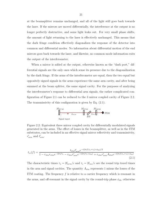
figuration <strong>of</strong> Figure 2.1 can be reduced to the 3 mirror coupled cavity <strong>of</strong> Figure 2.2.<br />
The transmissivity <strong>of</strong> this configuration is given by Eq. (2.1).<br />
MET M MIT M MSEM<br />
Signal input<br />
φarm<br />
Figure 2.2: Equivalent three mirror coupled cavity for differentially modulated signals<br />
generated in the arms. The effect <strong>of</strong> losses in the beamsplitter, as well as in the ITM<br />
substrates, can be included in an effective signal mirror reflectivity and transmissivity,<br />
r ′ sem and t ′ sem.<br />
tcc(f) =<br />
BS<br />
φsec<br />
titmt ′ seme −i(2πf(τa+τs)+φdt)/2<br />
¡<br />
¡<br />
PD3<br />
1 − ritmretme −i2πfτa − ritmr ′ seme −i(2πfτs+φdt) + retmr ′ semAitme −i(2πf(τa+τs)+φdt)<br />
(2.1)<br />
The characteristic times τa = 2larm/c and τs = 2lsec/c are the round trip travel times<br />
in the arm and signal cavities. The quantity Aitm represents 1 minus the losses <strong>of</strong> the<br />
ITM coating. The frequency f is relative to a carrier frequency which is resonant in<br />
the arms, and <strong>of</strong>f-resonant in the signal cavity by the round-trip phase φdt, otherwise