Evaluation of Measurement Uncertainty of Radiated EMC Tests in ...
Evaluation of Measurement Uncertainty of Radiated EMC Tests in ...
Evaluation of Measurement Uncertainty of Radiated EMC Tests in ...

Create successful ePaper yourself
Turn your PDF publications into a flip-book with our unique Google optimized e-Paper software.
108 T. Schrader et al.: <strong>Evaluation</strong> <strong>of</strong> <strong>Measurement</strong> <strong>Uncerta<strong>in</strong>ty</strong> <strong>of</strong> <strong>Radiated</strong> <strong>EMC</strong> <strong>Tests</strong><br />
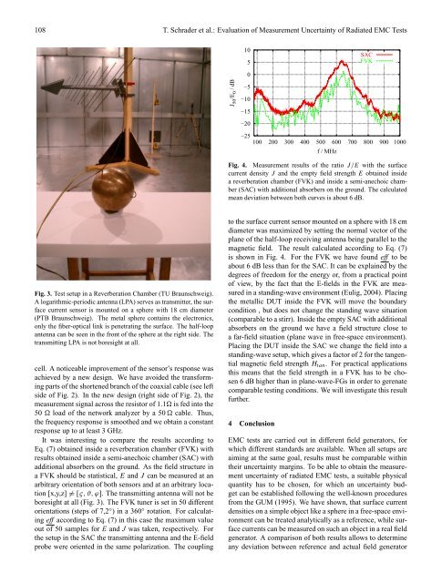
Fig. 3. Test setup <strong>in</strong> a Reverberation Chamber (TU Braunschweig).<br />
A logarithmic-periodic antenna (LPA) serves as transmitter, the surface<br />
current sensor is mounted on a sphere with 18 cm diameter<br />
(PTB Braunschweig). The metal sphere conta<strong>in</strong>s the electronics,<br />
only the fiber-optical l<strong>in</strong>k is penetrat<strong>in</strong>g the surface. The half-loop<br />
antenna can be seen <strong>in</strong> the front <strong>of</strong> the sphere at the right side. The<br />
transmitt<strong>in</strong>g LPA is not boresight at all.<br />
cell. A noticeable improvement <strong>of</strong> the sensor’s response was<br />
achieved by a new design. We have avoided the transform<strong>in</strong>g<br />
parts <strong>of</strong> the shortened branch <strong>of</strong> the coaxial cable (see left<br />
side <strong>of</strong> Fig. 2). In the new design (right side <strong>of</strong> Fig. 2), the<br />
measurement signal across the resistor <strong>of</strong> 1.1� is fed <strong>in</strong>to the<br />
50 � load <strong>of</strong> the network analyzer by a 50 � cable. Thus,<br />
the frequency response is smoothed and we obta<strong>in</strong> a constant<br />
response up to at least 3 GHz.<br />
It was <strong>in</strong>terest<strong>in</strong>g to compare the results accord<strong>in</strong>g to<br />
Eq. (7) obta<strong>in</strong>ed <strong>in</strong>side a reverberation chamber (FVK) with<br />
results obta<strong>in</strong>ed <strong>in</strong>side a semi-anechoic chamber (SAC) with<br />
additional absorbers on the ground. As the field structure <strong>in</strong><br />
a FVK should be statistical, E and J can be measured at an<br />
arbitrary orientation <strong>of</strong> both sensors and at an arbitrary location<br />
[x,y,z] �= [ς, ϑ, ϕ]. The transmitt<strong>in</strong>g antenna will not be<br />
boresight at all (Fig. 3). The FVK tuner is set <strong>in</strong> 50 different<br />
orientations (steps <strong>of</strong> 7,2 ◦ ) <strong>in</strong> a 360 ◦ rotation. For calculat<strong>in</strong>g<br />
eff accord<strong>in</strong>g to Eq. (7) <strong>in</strong> this case the maximum value<br />
out <strong>of</strong> 50 samples for E and J was taken, respectively. For<br />
the setup <strong>in</strong> the SAC the transmitt<strong>in</strong>g antenna and the E-field<br />
probe were oriented <strong>in</strong> the same polarization. The coupl<strong>in</strong>g<br />
J 50 /E 0 / dB<br />
10<br />
5<br />
0<br />
−5<br />
−10<br />
−15<br />
−20<br />
−25<br />
100 200 300 400 500 600 700 800 900 1000<br />
f / MHz<br />
SAC<br />
FVK<br />
Fig. 4. <strong>Measurement</strong> results <strong>of</strong> the ratio J/E with the surface<br />
current density J and the empty field strength E obta<strong>in</strong>ed <strong>in</strong>side<br />
a reverberation chamber (FVK) and <strong>in</strong>side a semi-anechoic chamber<br />
(SAC) with additional absorbers on the ground. The calculated<br />
mean deviation between both curves is about 6 dB.<br />
to the surface current sensor mounted on a sphere with 18 cm<br />
diameter was maximized by sett<strong>in</strong>g the normal vector <strong>of</strong> the<br />
plane <strong>of</strong> the half-loop receiv<strong>in</strong>g antenna be<strong>in</strong>g parallel to the<br />
magnetic field. The result calculated accord<strong>in</strong>g to Eq. (7)<br />
is shown <strong>in</strong> Fig. 4. For the FVK we have found eff to be<br />
about 6 dB less than for the SAC. It can be expla<strong>in</strong>ed by the<br />
degrees <strong>of</strong> freedom for the energy or, from a practical po<strong>in</strong>t<br />
<strong>of</strong> view, by the fact that the E-fields <strong>in</strong> the FVK are measured<br />
<strong>in</strong> a stand<strong>in</strong>g-wave environment (Eulig, 2004). Plac<strong>in</strong>g<br />
the metallic DUT <strong>in</strong>side the FVK will move the boundary<br />
condition , but does not change the stand<strong>in</strong>g wave situation<br />
(comparable to a stirr). Inside the empty SAC with additional<br />
absorbers on the ground we have a field structure close to<br />
a far-field situation (plane wave <strong>in</strong> free-space environment).<br />
Plac<strong>in</strong>g the DUT <strong>in</strong>side the SAC we change the field <strong>in</strong>to a<br />
stand<strong>in</strong>g-wave setup, which gives a factor <strong>of</strong> 2 for the tangential<br />
magnetic field strength Htan. For practical applications<br />
this means that the field strength <strong>in</strong> a FVK has to be chosen<br />
6 dB higher than <strong>in</strong> plane-wave-FGs <strong>in</strong> order to gerenate<br />
comparable test<strong>in</strong>g conditions. We will <strong>in</strong>vestigate this result<br />
further.<br />
4 Conclusion<br />
<strong>EMC</strong> tests are carried out <strong>in</strong> different field generators, for<br />
which different standards are available. When all setups are<br />
aim<strong>in</strong>g at the same goal, results must be comparable with<strong>in</strong><br />
their uncerta<strong>in</strong>ty marg<strong>in</strong>s. To be able to obta<strong>in</strong> the measurement<br />
uncerta<strong>in</strong>ty <strong>of</strong> radiated <strong>EMC</strong> tests, a suitable physical<br />
quantity has to be chosen, for which an uncerta<strong>in</strong>ty budget<br />
can be established follow<strong>in</strong>g the well-known procedures<br />
from the GUM (1995). We have shown, that surface current<br />
densities on a simple object like a sphere <strong>in</strong> a free-space environment<br />
can be treated analytically as a reference, while surface<br />
currents can be measured on such an object <strong>in</strong> a real field<br />
generator. A comparison <strong>of</strong> both results allows to determ<strong>in</strong>e<br />
any deviation between reference and actual field generator