Evaluation of Measurement Uncertainty of Radiated EMC Tests in ...
Evaluation of Measurement Uncertainty of Radiated EMC Tests in ...
Evaluation of Measurement Uncertainty of Radiated EMC Tests in ...

You also want an ePaper? Increase the reach of your titles
YUMPU automatically turns print PDFs into web optimized ePapers that Google loves.
Advances <strong>in</strong> Radio Science, 3, 105–109, 2005<br />
SRef-ID: 1684-9973/ars/2005-3-105<br />
© Copernicus GmbH 2005<br />
Advances <strong>in</strong><br />
Radio Science<br />
<strong>Evaluation</strong> <strong>of</strong> <strong>Measurement</strong> <strong>Uncerta<strong>in</strong>ty</strong> <strong>of</strong> <strong>Radiated</strong> <strong>EMC</strong> <strong>Tests</strong> <strong>in</strong><br />
Arbitrary Field Generators us<strong>in</strong>g Surface Currents on DUT<br />
T. Schrader 1 , K. Münter 1 , M. Spitzer 1 , N. Eulig 2 , and A. Enders 2<br />
1 Physikalisch-Technische Bundesanstalt, AG 2.21, Bundesallee 100, 38116 Braunschweig, Germany<br />
2 Institut für Elektromagnetische Verträglichkeit, Technische Universität Braunschweig, Schle<strong>in</strong>itzstraße 23, 38106<br />
Braunschweig, Germany<br />
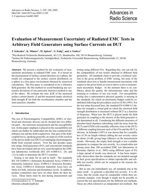
Abstract. We present a method for the evaluation <strong>of</strong> measurement<br />
uncerta<strong>in</strong>ty <strong>in</strong> radiated <strong>EMC</strong> tests. It is based on<br />
the measurement <strong>of</strong> surface current densities on a sphere, the<br />
results are compared to the surface current distribution on<br />
a sphere <strong>in</strong> a free-space environment obta<strong>in</strong>ed by numerical<br />
calculations. The free-space is considered to be a reference<br />
field generator. By this method we avoid burden<strong>in</strong>g any systematic<br />
deviations <strong>of</strong> one particular (historic) method to any<br />
<strong>of</strong> the others. We evaluate the ratio J/E <strong>of</strong> the measured<br />
surface current density J and the measured empty electrical<br />
field strength E for both the reverberation chamber and the<br />
semi-anechoic chamber.<br />
1 Introduction<br />
The test <strong>of</strong> Electromagnetic Compatibility (<strong>EMC</strong>) <strong>of</strong> electrical<br />
and electronic devices can be divided <strong>in</strong>to two different<br />
parts – the emissions measurement and the susceptibility<br />
test. In this paper emphasis is placed on the susceptibility test<br />
which can further be subdivided <strong>in</strong>to the l<strong>in</strong>e-conducted disturbance<br />
test and the field-coupled test. One part <strong>of</strong> the fieldcoupled<br />
test is, speak<strong>in</strong>g generally, an analysis <strong>of</strong> the reaction<br />
<strong>of</strong> the device under test (DUT) on imp<strong>in</strong>g<strong>in</strong>g electromagnetic<br />
fields from external sources. Over the last decades many<br />
test setups, field generators (FG), and concomitant standards<br />
have been developed and are now used throughout the <strong>EMC</strong><br />
test laboratories worldwide (IEC EN 61000-4-3, -20, and<br />
-21) <strong>in</strong> order to determ<strong>in</strong>e the DUT’s reaction.<br />
Test<strong>in</strong>g is not done for an end <strong>in</strong> itself. The standards<br />
IEC EN 61000-6-1 (Immunity Residential Area), 61000-6-2<br />
(Immunity Industrial Area), 61000-6-3 (Emission Residential<br />
Area), 61000-6-4 (Emission Industrial Area) have set<br />
limits for both, emission and disturbance levels. In addition,<br />
product committees may have set other limits for their devices.<br />
These limits must be met dur<strong>in</strong>g measurement and<br />
Correspondence to: T. Schrader<br />
(thorsten.schrader@ptb.de)<br />
test<strong>in</strong>g us<strong>in</strong>g different FGs. Regard<strong>in</strong>g this, one can ask for<br />
the comparability <strong>of</strong> test results obta<strong>in</strong>ed <strong>in</strong> different field<br />
generators. All standards claim to provide a technical solution<br />
to the given problem <strong>of</strong> <strong>EMC</strong> test<strong>in</strong>g, but none <strong>of</strong> the<br />
standards show how to handle measurement uncerta<strong>in</strong>ty with<br />
respect to the given limits or even to derive a test or measurement<br />
uncerta<strong>in</strong>ty budget. At the moment there is no confidence<br />
about the quality, the <strong>in</strong>formational value and the<br />
mean<strong>in</strong>g or evidence <strong>of</strong> any test result. For susceptibility<br />
test<strong>in</strong>g also a representative physical quantity is miss<strong>in</strong>g <strong>in</strong><br />
the standards, for which an uncerta<strong>in</strong>ty budget could be established<br />
follow<strong>in</strong>g the procedures used <strong>in</strong> GUM (1995). For<br />
the test setup discussed here, the standard EN 61000-4-3 def<strong>in</strong>es<br />
for example a virtual grid on which the electrical field<br />
strength distribution is measured without DUT as a function<br />
<strong>of</strong> frequency. When now the DUT is placed <strong>in</strong>side the field<br />
generator its coupl<strong>in</strong>g to the <strong>in</strong>terior <strong>of</strong> the field generator is<br />
not determ<strong>in</strong>ed at all. Consider<strong>in</strong>g the different structures <strong>of</strong><br />
absorber-l<strong>in</strong>ed chambers (absorb<strong>in</strong>g walls far away from the<br />
DUT) and GTEM cells (metallic reflectors close to the DUT)<br />
a different coupl<strong>in</strong>g between each <strong>of</strong> the FGs and the DUT is<br />
obvious. In Schrader (1997) it was shown that for a metallic<br />
box <strong>of</strong> 30 cm length without cabl<strong>in</strong>g the test severity varies<br />
by about ±4 dB, giv<strong>in</strong>g large <strong>in</strong>fluence on the measurement<br />
results. Obviously, the empty field strength is not a suitable<br />
parameter to compare the test severity. In a round-rob<strong>in</strong> test<br />
among more than 100 accredited <strong>EMC</strong> test laboratories <strong>in</strong><br />
Germany (Spitzer et al., 2003) us<strong>in</strong>g different types <strong>of</strong> FG<br />
a large spread <strong>of</strong> results was observed. It has been empirically<br />
shown there that the standards are not detailed enough<br />
<strong>in</strong> their given specifications to obta<strong>in</strong> reproducible and reliable<br />
test results, which can be assigned to the reasons described<br />
above.<br />
But as one can immediately see, all standards aim at the<br />
same result – to generate a specified test severity. It is obvious,<br />
that the results must be comparable with<strong>in</strong> their uncerta<strong>in</strong>ty<br />
marg<strong>in</strong>s, even though it might not be possible to<br />
convert the test specifications for the different test methods.<br />
These are <strong>of</strong>ten referred to as <strong>in</strong>dependent test methods. But
106 T. Schrader et al.: <strong>Evaluation</strong> <strong>of</strong> <strong>Measurement</strong> <strong>Uncerta<strong>in</strong>ty</strong> <strong>of</strong> <strong>Radiated</strong> <strong>EMC</strong> <strong>Tests</strong><br />
<strong>in</strong> case they are not comparable at all, the question arises<br />
whether any <strong>of</strong> the methods represents the susceptibility <strong>of</strong><br />
the DUT. The problem so far was to f<strong>in</strong>d a measurable quantity<br />
which subsumes all <strong>in</strong>fluences at once and could be<br />
l<strong>in</strong>ked to any <strong>in</strong>dependent reference. The deviation <strong>of</strong> measurements<br />
from the reference, which might be just a theoretical<br />
value, would help to determ<strong>in</strong>e the uncerta<strong>in</strong>ty for the<br />
actual test setup.<br />
This work describes a method how to obta<strong>in</strong> a physical<br />
quantity which describes all <strong>in</strong>fluences on the measurement<br />
uncerta<strong>in</strong>ty for devices with metallic enclosures. Influences<br />
are, for example, the field strength level, the field structure<br />
(or 3-D-components), any near- or far-field effect, any coupl<strong>in</strong>g<br />
between the outer shell <strong>of</strong> the DUT to the <strong>in</strong>terior <strong>of</strong> the<br />
FG, and any resonance <strong>in</strong>side the FG and / or <strong>in</strong>side the DUT.<br />
With this method it is rather simple to derive the uncerta<strong>in</strong>ty<br />
budget for <strong>EMC</strong> test<strong>in</strong>g without burden<strong>in</strong>g any systematic<br />
error <strong>of</strong> one particular (historic) method to any <strong>of</strong> the others.<br />
Some results obta<strong>in</strong>ed <strong>in</strong> different field generators are given.<br />
2 Theory<br />
In order to f<strong>in</strong>d any l<strong>in</strong>k between the electromagnetic field<br />
generated for a test purpose and the actual disturbance level,<br />
we look at the <strong>in</strong>terfaces which can basically couple energy<br />
from the field to the electronics <strong>of</strong> the DUT possibly yield<strong>in</strong>g<br />
a malfunction <strong>of</strong> the DUT. The second topic to be discussed<br />
is how to obta<strong>in</strong> the degree <strong>of</strong> equivalence <strong>of</strong> tests performed<br />
<strong>in</strong> different FGs. Comb<strong>in</strong><strong>in</strong>g both issues will guide us to a<br />
possible solution <strong>of</strong> our problem.<br />
In order to expla<strong>in</strong> our ideas, we are consider<strong>in</strong>g a metallic<br />
sphere <strong>in</strong> a free-space environment. S<strong>in</strong>ce many <strong>of</strong> the enclosures<br />
<strong>of</strong> DUTs are metallic or metalized cases with open<strong>in</strong>gs<br />
or cable entry po<strong>in</strong>ts, this seems to be reasonable. The metal<br />
enclosure will at least serve as a worst-case situation and it<br />
reduces the problem level to a clear and manageable situation.<br />
We are assum<strong>in</strong>g the sk<strong>in</strong> depth be<strong>in</strong>g small compared<br />
to the thickness <strong>of</strong> the metalized layer <strong>of</strong> the sphere. That<br />
way we have only coupl<strong>in</strong>g through def<strong>in</strong>ed ports. Now, consider<strong>in</strong>g<br />
a plane wave imp<strong>in</strong>g<strong>in</strong>g on the sphere be<strong>in</strong>g located<br />
<strong>in</strong> a free-space environment, surface currents and charges<br />
will be driven by the external electromagnetic field. Let us<br />
assume furthermore one simple slot with a high aspect ratio<br />
be<strong>in</strong>g the only path from the exterior to the <strong>in</strong>terior <strong>of</strong> the<br />
sphere. We then can treat the slot as a “directional coupler”,<br />
because it provides a high coupl<strong>in</strong>g factor <strong>in</strong>to the sphere if<br />
the surface current has a direction perpendicular to the slot’s<br />
largest dimension. For the direction parallel to the slot the<br />
coupl<strong>in</strong>g is much lower. Only the slot geometry determ<strong>in</strong>es<br />
the tensor which describes the coupl<strong>in</strong>g factor <strong>of</strong> the slot<br />
(Sturm, Römer, 2002). Therefore, the coupl<strong>in</strong>g factor will<br />
rema<strong>in</strong> the same, even if the shield<strong>in</strong>g effectiveness <strong>of</strong> an<br />
enclosure with one slot is measured <strong>in</strong> different FGs. However,<br />
if we consider the amount <strong>of</strong> energy coupled <strong>in</strong>to the<br />
DUT, Schrader (1997) has shown <strong>in</strong> experiments, that the<br />
energy is also dependent on the different excitation, which is<br />
determ<strong>in</strong>ed by the actual charge and current distribution on<br />
the surface <strong>of</strong> the DUT. Sturm and Römer (2002) described<br />
these empirically based data <strong>in</strong> a more formal way.<br />
In case we are able to predict the coupl<strong>in</strong>g <strong>of</strong> a known<br />
source <strong>in</strong>to the metal sphere (e.g. by numerical calculation),<br />
we only have to determ<strong>in</strong>e the excitation <strong>of</strong> the coupl<strong>in</strong>g port<br />
and the backward <strong>in</strong>teraction from the sphere’s <strong>in</strong>terior to<br />
the exterior. It depends on the material’s properties whether<br />
resonances will occur <strong>in</strong>side the DUT or not. This was one<br />
<strong>of</strong> the problems measur<strong>in</strong>g the shield<strong>in</strong>g effectiveness <strong>of</strong> RF<br />
protection suits. By fill<strong>in</strong>g those partially with absorbers or<br />
other lossy material the unwanted and mislead<strong>in</strong>g resonances<br />
(Kl<strong>in</strong>kenbusch, 1998) are avoided. From now on we will use<br />
a closed sphere only, so we can disregard the backward <strong>in</strong>teraction.<br />
This way we have separated the <strong>in</strong>ternal from the<br />
external problem. But still, the excitation <strong>of</strong> the problem is<br />
the surface current and charge distribution. If we determ<strong>in</strong>e<br />
those on a sphere with given diameter <strong>in</strong>side a particular FG,<br />
we are able to compare these results with those obta<strong>in</strong>ed analytically<br />
on a sphere <strong>of</strong> the same diameter <strong>in</strong> a free-space<br />
environment (Schrader, 1997 and 2002). Of course a suitable<br />
measurement system is needed, provid<strong>in</strong>g amplitude and<br />
phase <strong>in</strong>formation <strong>of</strong> a signal proportional to a surface current<br />
density distribution (Schrader, 1997).<br />
To measure this, we have used a closed sphere with one<br />
surface current sensor mounted. The scatter<strong>in</strong>g <strong>of</strong> the sphere<br />
is <strong>in</strong>variant aga<strong>in</strong>st rotation, so we can sample the current on<br />
the whole surface by just a simple rotation <strong>of</strong> the DUT. In our<br />
<strong>in</strong>vestigation we neglect an <strong>in</strong>fluence <strong>of</strong> the sensor itself on<br />
the currents and surface fields, respectively. This <strong>in</strong>fluence<br />
needs further <strong>in</strong>vestigation and will be subject <strong>of</strong> one <strong>of</strong> the<br />
next papers.<br />
In order now to compare the currents, we segmented the<br />
surface <strong>in</strong>to N patch elements. For each patch we obta<strong>in</strong>ed<br />
the phasor for two orthogonal current components<br />
measured by the sensor and calculated by us<strong>in</strong>g the Method<strong>of</strong>-Moments<br />
(S<strong>in</strong>ger, Brüns, 2004). The amplitude and phase<br />
reference may be chosen arbitrarily on the DUT; we preferred<br />
the data measured on the patch be<strong>in</strong>g boresight to the<br />
transmitt<strong>in</strong>g antenna as reference.<br />
The surface current sensor (SCS) is basically a half-loop<br />
antenna and evaluates the well-known equation<br />
J = n × H tan<br />
with the surface current density J , the normal vector n <strong>of</strong> the<br />
surface and the vector <strong>of</strong> the tangential magnetic field H tan.<br />
With this sensor we obta<strong>in</strong>ed the phasors <strong>of</strong> the measured<br />
orthogonal current components J µ,i,f,F G , J ν,i,f,F G |N for<br />
each patch i on one particular sphere at the frequency f <strong>in</strong><br />
one particular FG (we have used a sphere with 50 cm diameter).<br />
Us<strong>in</strong>g “Concept” we calculated for each patch i the orthogonal<br />
complex-valued phasors J µ,i,f,F S , J ν,i,f,F S | N for<br />
the free-space environment as the reference field generator.<br />
In order to determ<strong>in</strong>e the difference current vector for each<br />
patch i we calculate first the phasor difference for both current<br />
components on each patch i<br />
�J µ,i,f = J µ,i,f,F G − J µ,i,f,F S<br />
(1)<br />
(2)
T. Schrader et al.: <strong>Evaluation</strong> <strong>of</strong> <strong>Measurement</strong> <strong>Uncerta<strong>in</strong>ty</strong> <strong>of</strong> <strong>Radiated</strong> <strong>EMC</strong> <strong>Tests</strong> 107<br />
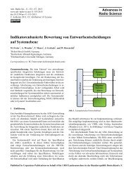
Fig. 1. Surface current sensor output <strong>in</strong> a µTEM cell, where the<br />
cell’s ceil<strong>in</strong>g is replaced with the sensor’s groundplane. For 90 ◦<br />
and 270 ◦ the sensor is decoupled from the magnetic field, while for<br />
0 ◦ and 180 ◦ the symmetry <strong>of</strong> the sensor can be accessed.<br />
�J ν,i,f = J ν,i,f,F G − J ν,i,f,F S . (3)<br />
The magnitude <strong>of</strong> the difference current vector for each patch<br />
i can the be obta<strong>in</strong>ed by<br />
� �<br />
�<br />
� �<br />
� �<br />
2 � �2 ��J i,f � = �J µ,i,f + �J ν,i,f . (4)<br />
Us<strong>in</strong>g Eq. (4) we calculate now the mean deviation for all M<br />
frequencies and for all N patches i accord<strong>in</strong>g to<br />
� �<br />
��J �<br />
1 1<br />
N,M = ·<br />
N M ·<br />
M� N�<br />
�<br />
� �2 � �2 �J µ,i,f + �J ν,i,f .(5)<br />
f =1 i=1<br />
It depends on the relationship between the size <strong>of</strong> the sphere<br />
and the frequency range how many patches and samples <strong>of</strong><br />
the surface current distribution are needed to describe any<br />
deviation <strong>in</strong> one particular FG. This will be subject to further<br />
<strong>in</strong>vestigations.<br />
It might be <strong>in</strong>terest<strong>in</strong>g to normalize each component <strong>of</strong><br />
the current vector (Eqs. 2, 3) with the free-space values<br />
J µ,i,f,F S , J ν,i,f,F S , otherwise we have weighted the results<br />
by omitt<strong>in</strong>g contributions from areas <strong>of</strong> the surface be<strong>in</strong>g less<br />
excited from the direct electromagnetic wave.<br />
We used the mean deviation accord<strong>in</strong>g to Eq. (5) to evaluate<br />
which surface area is mostly effected by the FG. The<br />
relative spread <strong>of</strong> the deviation rsd (Eq. 6) shows, whether a<br />
significant evidence is existent and if so, at which part <strong>of</strong> the<br />
surface it can be found.<br />
⎛�<br />
�<br />
� �<br />
��J i,f � −<br />
rsd (f ) = max ⎝<br />
i=1...N<br />
� �⎞<br />
��J �<br />
N,M<br />
� � ⎠ (6)<br />
��J �<br />
N,M<br />
The plot <strong>of</strong> rsd(f) vs. frequency f could give some <strong>in</strong>sight,<br />
whether the <strong>in</strong>fluence is <strong>of</strong> narrow or broadband type. All <strong>of</strong><br />
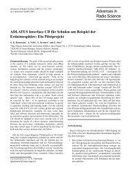
Fig. 2. Former (left) and new (right) design <strong>of</strong> the surface current<br />
density sensor.<br />
these effects and correlations will be <strong>in</strong>vestigated <strong>in</strong> the future,<br />
but one can already be analyzed now, which is the ratio<br />
eff between the empty field strength E x,y,z,f measured with<br />
the E-field sensor at locus x, y, z <strong>in</strong> the FG and the surface<br />
current J ς,ϑ,ϕ,f on the patch i <strong>of</strong> the sphere <strong>in</strong> the same FG.<br />
eff = J ς,ϑ,ϕ,f<br />
E x,y,z,f<br />
The result <strong>of</strong> Eq. (7) can quasi be treated as an efficiency,<br />
namely to which extent the electrical field strength (which is<br />
the only <strong>in</strong>dication for test severity <strong>in</strong> <strong>EMC</strong> test<strong>in</strong>g now) is<br />
converted to a surface current on a DUT (which is the more<br />
important physical value to obta<strong>in</strong> uncerta<strong>in</strong>ty and comparability).<br />
3 <strong>Measurement</strong> Setup<br />
To obta<strong>in</strong> surface current distributions on a DUT a probe system<br />
based on a fiber-optical l<strong>in</strong>k was used here (Schrader,<br />
1997). It is implemented <strong>in</strong> a loop (measurement setup) consist<strong>in</strong>g<br />
<strong>of</strong> a vector network analyzer (VNA), a power amplifier<br />
and a transmitt<strong>in</strong>g antenna <strong>in</strong> a semi-anechoic chamber<br />
as FG. The scatter<strong>in</strong>g parameter <strong>of</strong> forward transmission S21<br />
is measured and stored <strong>in</strong> the frequency range from 80 MHz<br />
to 1000 MHz.<br />
To avoid any <strong>in</strong>fluence <strong>of</strong> power variations the actual forward<br />
power can be taken <strong>in</strong>to account us<strong>in</strong>g a 4-sampler-<br />
VNA. Instead <strong>of</strong> the reflected <strong>in</strong>cident signal b1, we feed the<br />
forward power branch <strong>of</strong> a directional coupler as <strong>in</strong>put quantity<br />
<strong>in</strong>to the appropriate channel <strong>of</strong> the VNA.<br />
The surface current sensor (SCS) consists <strong>of</strong> a half-loop<br />
antenna over its “groundplane”. Usually a th<strong>in</strong> semi-rigid<br />
cable is used as half-loop, with the outer conductor cut along<br />
the circumference. As the cut is symmetrical, the E-field <strong>in</strong>fluence<br />
is reduced by balanc<strong>in</strong>g the sensor signal. To show<br />
this, results were obta<strong>in</strong>ed <strong>in</strong> a µTEM cell, where its ceil<strong>in</strong>g<br />
was replaced by a sensor’s groundplane. By rotation <strong>of</strong> the<br />
groundplane <strong>of</strong> 90 ◦ , 180 ◦ and 270 ◦ the change <strong>in</strong> the sensor<br />
output is observed. As it can be seen <strong>in</strong> Fig. 1 the suppression<br />
<strong>of</strong> E is better than 20 dB up to 1 GHz. The sensor<br />
was not calibrated dur<strong>in</strong>g our <strong>in</strong>vestigations, but we recommend<br />
a calibration traceable to the SI units us<strong>in</strong>g a µTEM<br />
(7)
108 T. Schrader et al.: <strong>Evaluation</strong> <strong>of</strong> <strong>Measurement</strong> <strong>Uncerta<strong>in</strong>ty</strong> <strong>of</strong> <strong>Radiated</strong> <strong>EMC</strong> <strong>Tests</strong><br />
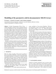
Fig. 3. Test setup <strong>in</strong> a Reverberation Chamber (TU Braunschweig).<br />
A logarithmic-periodic antenna (LPA) serves as transmitter, the surface<br />
current sensor is mounted on a sphere with 18 cm diameter<br />
(PTB Braunschweig). The metal sphere conta<strong>in</strong>s the electronics,<br />
only the fiber-optical l<strong>in</strong>k is penetrat<strong>in</strong>g the surface. The half-loop<br />
antenna can be seen <strong>in</strong> the front <strong>of</strong> the sphere at the right side. The<br />
transmitt<strong>in</strong>g LPA is not boresight at all.<br />
cell. A noticeable improvement <strong>of</strong> the sensor’s response was<br />
achieved by a new design. We have avoided the transform<strong>in</strong>g<br />
parts <strong>of</strong> the shortened branch <strong>of</strong> the coaxial cable (see left<br />
side <strong>of</strong> Fig. 2). In the new design (right side <strong>of</strong> Fig. 2), the<br />
measurement signal across the resistor <strong>of</strong> 1.1� is fed <strong>in</strong>to the<br />
50 � load <strong>of</strong> the network analyzer by a 50 � cable. Thus,<br />
the frequency response is smoothed and we obta<strong>in</strong> a constant<br />
response up to at least 3 GHz.<br />
It was <strong>in</strong>terest<strong>in</strong>g to compare the results accord<strong>in</strong>g to<br />
Eq. (7) obta<strong>in</strong>ed <strong>in</strong>side a reverberation chamber (FVK) with<br />
results obta<strong>in</strong>ed <strong>in</strong>side a semi-anechoic chamber (SAC) with<br />
additional absorbers on the ground. As the field structure <strong>in</strong><br />
a FVK should be statistical, E and J can be measured at an<br />
arbitrary orientation <strong>of</strong> both sensors and at an arbitrary location<br />
[x,y,z] �= [ς, ϑ, ϕ]. The transmitt<strong>in</strong>g antenna will not be<br />
boresight at all (Fig. 3). The FVK tuner is set <strong>in</strong> 50 different<br />
orientations (steps <strong>of</strong> 7,2 ◦ ) <strong>in</strong> a 360 ◦ rotation. For calculat<strong>in</strong>g<br />
eff accord<strong>in</strong>g to Eq. (7) <strong>in</strong> this case the maximum value<br />
out <strong>of</strong> 50 samples for E and J was taken, respectively. For<br />
the setup <strong>in</strong> the SAC the transmitt<strong>in</strong>g antenna and the E-field<br />
probe were oriented <strong>in</strong> the same polarization. The coupl<strong>in</strong>g<br />
J 50 /E 0 / dB<br />
10<br />
5<br />
0<br />
−5<br />
−10<br />
−15<br />
−20<br />
−25<br />
100 200 300 400 500 600 700 800 900 1000<br />
f / MHz<br />
SAC<br />
FVK<br />
Fig. 4. <strong>Measurement</strong> results <strong>of</strong> the ratio J/E with the surface<br />
current density J and the empty field strength E obta<strong>in</strong>ed <strong>in</strong>side<br />
a reverberation chamber (FVK) and <strong>in</strong>side a semi-anechoic chamber<br />
(SAC) with additional absorbers on the ground. The calculated<br />
mean deviation between both curves is about 6 dB.<br />
to the surface current sensor mounted on a sphere with 18 cm<br />
diameter was maximized by sett<strong>in</strong>g the normal vector <strong>of</strong> the<br />
plane <strong>of</strong> the half-loop receiv<strong>in</strong>g antenna be<strong>in</strong>g parallel to the<br />
magnetic field. The result calculated accord<strong>in</strong>g to Eq. (7)<br />
is shown <strong>in</strong> Fig. 4. For the FVK we have found eff to be<br />
about 6 dB less than for the SAC. It can be expla<strong>in</strong>ed by the<br />
degrees <strong>of</strong> freedom for the energy or, from a practical po<strong>in</strong>t<br />
<strong>of</strong> view, by the fact that the E-fields <strong>in</strong> the FVK are measured<br />
<strong>in</strong> a stand<strong>in</strong>g-wave environment (Eulig, 2004). Plac<strong>in</strong>g<br />
the metallic DUT <strong>in</strong>side the FVK will move the boundary<br />
condition , but does not change the stand<strong>in</strong>g wave situation<br />
(comparable to a stirr). Inside the empty SAC with additional<br />
absorbers on the ground we have a field structure close to<br />
a far-field situation (plane wave <strong>in</strong> free-space environment).<br />
Plac<strong>in</strong>g the DUT <strong>in</strong>side the SAC we change the field <strong>in</strong>to a<br />
stand<strong>in</strong>g-wave setup, which gives a factor <strong>of</strong> 2 for the tangential<br />
magnetic field strength Htan. For practical applications<br />
this means that the field strength <strong>in</strong> a FVK has to be chosen<br />
6 dB higher than <strong>in</strong> plane-wave-FGs <strong>in</strong> order to gerenate<br />
comparable test<strong>in</strong>g conditions. We will <strong>in</strong>vestigate this result<br />
further.<br />
4 Conclusion<br />
<strong>EMC</strong> tests are carried out <strong>in</strong> different field generators, for<br />
which different standards are available. When all setups are<br />
aim<strong>in</strong>g at the same goal, results must be comparable with<strong>in</strong><br />
their uncerta<strong>in</strong>ty marg<strong>in</strong>s. To be able to obta<strong>in</strong> the measurement<br />
uncerta<strong>in</strong>ty <strong>of</strong> radiated <strong>EMC</strong> tests, a suitable physical<br />
quantity has to be chosen, for which an uncerta<strong>in</strong>ty budget<br />
can be established follow<strong>in</strong>g the well-known procedures<br />
from the GUM (1995). We have shown, that surface current<br />
densities on a simple object like a sphere <strong>in</strong> a free-space environment<br />
can be treated analytically as a reference, while surface<br />
currents can be measured on such an object <strong>in</strong> a real field<br />
generator. A comparison <strong>of</strong> both results allows to determ<strong>in</strong>e<br />
any deviation between reference and actual field generator
T. Schrader et al.: <strong>Evaluation</strong> <strong>of</strong> <strong>Measurement</strong> <strong>Uncerta<strong>in</strong>ty</strong> <strong>of</strong> <strong>Radiated</strong> <strong>EMC</strong> <strong>Tests</strong> 109<br />
without burden<strong>in</strong>g any systematic error <strong>of</strong> one particular (historic)<br />
method to any <strong>of</strong> the others. Compar<strong>in</strong>g the ratios <strong>of</strong><br />
J/E obta<strong>in</strong>ed <strong>in</strong> the SAC and <strong>in</strong> the FVK, a deviation <strong>of</strong><br />
6 dB is observed, which can be expla<strong>in</strong>ed by the degrees <strong>of</strong><br />
freedom <strong>of</strong> the energy.<br />
References<br />
Eulig, N.: Eignung der Feldvariablen Kammer (FVK) für EMV-<br />
Störfestigkeitstests, Dissertation TU Braunschweig, Shaker Verlag,<br />
Aachen, ISBN 3-8322-2945-0, 2004.<br />
Guide to the Expression <strong>of</strong> <strong>Uncerta<strong>in</strong>ty</strong> <strong>in</strong> <strong>Measurement</strong> (GUM),<br />
first edition 1993, corrected and repr<strong>in</strong>ted 1995.<br />
IEC EN 61000-4-3 (<strong>EMC</strong>) Part 4-3: Test<strong>in</strong>g and <strong>Measurement</strong><br />
Techniques – <strong>Radiated</strong>, radio-frequency, electromagnetic field<br />
immunity test, Basic <strong>EMC</strong> publication, 2002.<br />
IEC EN 61000-4-20 (<strong>EMC</strong>) Part 4-20: Test<strong>in</strong>g and <strong>Measurement</strong><br />
Techniques –, Emission and Immunity test<strong>in</strong>g <strong>in</strong> transverse electromagnetic<br />
(TEM) waveguides, 2000.<br />
IEC EN 61000-4-21 (<strong>EMC</strong>) Part 4-21: Test<strong>in</strong>g and <strong>Measurement</strong><br />
Techniques –, Emission and Immunity test<strong>in</strong>g <strong>in</strong> Reverberation<br />
Chambers, 2003.<br />
IEC EN 61000-6-1 (<strong>EMC</strong>) Part 6-1: Generic Standards – Immunity<br />
for Residential, commercial and light-<strong>in</strong>dustrial environments,<br />
2005.<br />
IEC EN 61000-6-2 (<strong>EMC</strong>) Part 6-2: Generic Standards – Immunity<br />
for <strong>in</strong>dustrial environments, 2002.<br />
IEC EN 61000-6-3 (<strong>EMC</strong>) Part 6-3: Generic Standards – Emission<br />
test<strong>in</strong>g for Residential, commercial and light-<strong>in</strong>dustrial environments,<br />
2002.<br />
IEC EN 61000-6-4 (<strong>EMC</strong>) Part 6-4: Generic Standards – Emission<br />
test<strong>in</strong>g for <strong>in</strong>dustrial environments, 20021.<br />
International Organization for Standardization (ISO).<br />
Kl<strong>in</strong>kenbusch, L.: Multipolanalyse des Schirmverhaltens bei transienter<br />
Störaussendung, <strong>in</strong>: Elektromagnetische Verträglichkeit<br />
EMV ’98, edited by: Schwab, A., Berl<strong>in</strong>-Offenbach: VDE-<br />
Verlag, 169–176, 1998.<br />
Schrader, T.: Vergleich von Feldgeneratoren für EMV-Prüfungen,<br />
Dissertation TU Braunschweig, Shaker Verlag, Aachen, ISBN<br />
3-8265-2782-8, 1997.<br />
Schrader, T.: A Semi-Analytical Method for the Determ<strong>in</strong>ation <strong>of</strong><br />
the Severity <strong>of</strong> <strong>Tests</strong> <strong>in</strong> <strong>Measurement</strong>s <strong>of</strong> the Immunity to Electromagnetic<br />
Interferences (<strong>EMC</strong>), Technisches Messen, 69, 2,<br />
70–76, 2002.<br />
S<strong>in</strong>ger, H. and Brüns, H.: Concept II: Code for the Numerical Computation<br />
<strong>of</strong> Electromagnetic Processes for Th<strong>in</strong> Wire and Th<strong>in</strong><br />
Shell Structures Includ<strong>in</strong>g Dielectrics, Department <strong>of</strong> Theoretical<br />
Electrical Eng<strong>in</strong>eer<strong>in</strong>g, TU Hamburg-Harburg, 2004.<br />
Spitzer, M., Münter, K., Pape, R., Glimm, J., and Dallwitz, L.:<br />
<strong>EMC</strong>-<strong>in</strong>tercomparison by DATech/RegTP/PTB – results, f<strong>in</strong>d<strong>in</strong>gs<br />
and conclusions, Technisches Messen, 70, 3, 151–162,<br />
2003.<br />
Sturm, R. and Römer, B.: Measur<strong>in</strong>g the Leakage <strong>of</strong> Gaskets, Technisches<br />
Messen, 69, 2, 102–107, 2002.