Recommendations TBM ITA - Underground Structures Worldwide ...
Recommendations TBM ITA - Underground Structures Worldwide ...
Recommendations TBM ITA - Underground Structures Worldwide ...

You also want an ePaper? Increase the reach of your titles
YUMPU automatically turns print PDFs into web optimized ePapers that Google loves.
Towards an<br />
improved use<br />
of underground<br />
Space<br />
ASSOCIATION<br />
INTERNATIONALE DES TRAVAUX<br />
EN SOUTERRAIN<br />
INTERNATIONAL<br />
TUNNELLING<br />
ASSOCIATION<br />
AITES <strong>ITA</strong><br />
In Consultative Status, Category II with the<br />
United Nations Economic and Social Council<br />
http://www.ita-aites.org<br />
Topic<br />
MECHANIZED TUNNELLING<br />
Title<br />
<strong>Recommendations</strong> and Guidelines for Tunnel Boring Machines (<strong>TBM</strong>s)<br />
Author<br />
<strong>ITA</strong> WG Mechanized Tunnelling<br />
published<br />
in "<strong>Recommendations</strong> and Guidelines for Tunnel Boring Machines (<strong>TBM</strong>s)",<br />
pp. 1 - 118, Year 2000<br />
by <strong>ITA</strong> - AITES, www.ita-aites.org<br />
Working Group: WG 14 - "Mechanized Tunnelling"<br />
Open Session, Seminar, Workshop: -<br />
Others: <strong>Recommendations</strong><br />
Abstract: -<br />
Résumé: -<br />
Remarks: This report contains four individual reports prepared by <strong>ITA</strong> Working Group No. 14 ("Mechanized<br />
Tunnelling"). The purpose of the reports is to provide comprehensive guidelines and recommendations for<br />
evaluating and selecting Tunnel Boring Machines (<strong>TBM</strong>s) for both soft ground and hard rock. The reports are<br />
contributed by representatives from seven countries as follows:<br />
I. "Guide lines for Selecting <strong>TBM</strong>s for Soft Ground", Japan and Norway<br />
II. "<strong>Recommendations</strong> of Selecting and Evaluating Tunnel Boring Machines", Germany, Switzerland and<br />
Austria<br />
III. "Guidelines for the Selection of <strong>TBM</strong>s", Italy<br />
IV. "New <strong>Recommendations</strong> on Choosing Mechanized Tunnelling Techniques", France<br />
Each report offers up to date technologies of mechanized tunneling for both hard and soft ground and includes,<br />
among others, classifications of <strong>TBM</strong>s, their application criteria, construction methods, ground supporting<br />
system and other equipment necessary for driving tunnels by <strong>TBM</strong>s.<br />
Since a cylindrical steel shield was first used for the construction of the Themes River Tunnel Crossing in<br />
England in 1823, tunnel works have been steadily mechanized. Especially, as urban tunneling was developed in<br />
the latter half of the 20th century, technological progress seen in this area was remarkable. Meanwhile, the<br />
circumstances surrounding tunnel construction have become increasingly complex and difficult. Tunneling<br />
technologies in recent years are developed by sophisticated and multi-disciplinary engineering principles to<br />
cope with the diverse physical, environmental and social circumstances. This report is intended to provide<br />
fundamental and useful knowledge of mechanical tunneling that can be used by designers, manufacturers and<br />
the end users of tunnel boring machines.<br />
It is hoped that this report provides common ground for understanding tunneling technologies among<br />
international tunneling communities and eventually helps establish a standard set of criteria for designing and<br />
utilizing tunnel boring machines.<br />
Secretariat : <strong>ITA</strong>-AITES c/o EPFL - Bât. GC – CH-1015 Lausanne - Switzerland<br />
Fax : +41 21 693 41 53 - Tel. : +41 21 693 23 10 - e-mail : secretariat@ita-aites.org - www.ita-aites.org
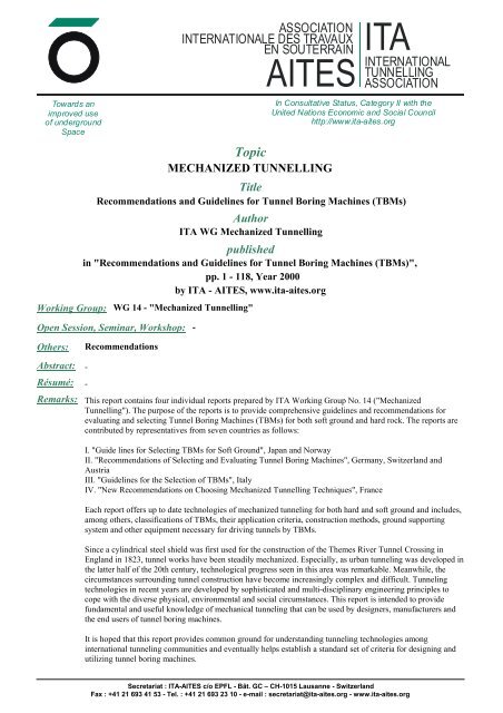
RECOMMENDATIONS AND GUIDELINES<br />
FOR TUNNEL BORING MACHINES (<strong>TBM</strong>s)<br />
WORKING GROUP N°14 - MECHANIZED TUNNELLING -<br />
INTERNATIONAL TUNNELLING ASSOCIATION<br />
TRIBUNE HORS SÉRIE<br />
MAI 2001 - ISSN 1267-8422<br />
ASSOCIATION<br />
INTERNATIONALE DES TRAVAUX<br />
EN SOUTERRAIN<br />
AITES<br />
<strong>ITA</strong><br />
INTERNATIONAL<br />
TUNNELLING<br />
ASSOCIATION
International Tunnelling Association<br />
25, Avenue François Mitterrand – Case nº1<br />
69674 BRON Cedex<br />
France<br />
TEL: 33(0) 4 78 26 04 55<br />
FAX: 33(0) 4 72 37 24 06<br />
e-mail: aites@imaginet.fr<br />
http://www.ita-aites.org<br />
© International Tunnelling Association. All rights reserved. No part of this publication may be<br />
distributed and/or reproduced, stored in a retrieval system or transmitted in any form or by any<br />
means, electronic, mechanical, photocopying, recording or otherwise , without the prior written<br />
permission of publisher, International Tunneling Association
Preface<br />
This report contains four individual reports prepared by <strong>ITA</strong> Working Group No. 14 (“Mechanized<br />
Tunneling”). The purpose of the reports is to provide comprehensive guidelines and<br />
recommendations for evaluating and selecting Tunnel Boring Machines (<strong>TBM</strong>s) for both soft ground<br />
and hard rock. The reports are contributed by representatives from seven countries as follows:<br />
I. “Guide lines for Selecting <strong>TBM</strong>s for Soft Ground”, Japan and Norway<br />
II. “<strong>Recommendations</strong> of Selecting and Evaluating Tunnel Boring Machines”, Germany,<br />
Switzerland and Austria<br />
III. “Guidelines for the Selection of <strong>TBM</strong>s”, Italy<br />
IV. “New <strong>Recommendations</strong> on Choosing Mechanized Tunnelling Techniques”, France<br />
Each report offers up to date technologies of mechanized tunneling for both hard and soft ground<br />
and includes, among others, classifications of <strong>TBM</strong>s, their application criteria, construction methods,<br />
ground supporting system and other equipment necessary for driving tunnels by <strong>TBM</strong>s.<br />
Since a cylindrical steel shield was first used for the construction of the Themes River Tunnel<br />
Crossing in England in 1823, tunnel works have been steadily mechanized. Especially, as urban<br />
tunneling was developed in the latter half of the 20 th century, technological progress seen in this area<br />
was remarkable. Meanwhile, the circumstances surrounding tunnel construction have become<br />
increasingly complex and difficult. Tunneling technologies in recent years are developed by<br />
sophisticated and multi-disciplinary engineering principles to cope with the diverse physical,<br />
environmental and social circumstances. This report is intended to provide fundamental and useful<br />
knowledge of mechanical tunneling that can be used by designers, manufacturers and the end users<br />
of tunnel boring machines.<br />
It is hoped that this report provides common ground for understanding tunneling technologies among<br />
international tunneling communities and eventually helps establish a standard set of criteria for<br />
designing and utilizing tunnel boring machines.<br />
Shoji Kuwahara<br />
Tutor, Working Group No. 14<br />
International Tunnelling Association
GENERAL CONTENTS<br />
I. GUIDELINES FOR SELECTING <strong>TBM</strong>S FOR SOFT GROUND<br />
by Japan and Norway<br />
1 Classification of tunnel excavation machine<br />
2 Investigation of existing conditions and applicability of <strong>TBM</strong><br />
3 Tunnel boring machine (<strong>TBM</strong>)<br />
4 Tunnels constructed by <strong>TBM</strong> in Japan<br />
APPENDIX: <strong>TBM</strong> Performance in hard rock<br />
II. RECOMMENDATIONS OF SELECTING AND EVALUATING<br />
TUNNEL BORING MACHINES<br />
by Germany, Switzerland and Austria<br />
1. Purpose of the recommendations<br />
2. Geotechnics<br />
3. Construction methods for mined tunnels<br />
4. Tunneling machines TM<br />
5. Relationship between geotechnics and tunneling machines<br />
III. GUIDELINES FOR THE SELECTION OF <strong>TBM</strong>S<br />
by Italy<br />
1. Classification and outlines of tunnel excavation machines<br />
2. Conditions for tunnel construction and selection of <strong>TBM</strong> tunneling method<br />
3. References<br />
IV. NEW RECOMMENDATIONS ON CHOOSING MECHANIZED<br />
TUNNELLING TECHNIQUES<br />
by France<br />
1. Purpose of these recommendations<br />
2. Mechanized tunnelling techniques<br />
3. Classification of mechanized tunneling Techniques<br />
4. Definition of the different mechanized tunnelling techniques classified in chapter 3<br />
5. Evaluation of parameters for choice of mechanized tunneling techniques<br />
6. Specific features of the different tunneling techniques<br />
7. Application of mechanized tunneling techniques<br />
8. Techniques accompanying mechanized tunneling<br />
9. Health & Safety
Guidelines for Selecting <strong>TBM</strong>s<br />
for Soft Ground<br />
<strong>ITA</strong> Working Group No. 14<br />
Mechanized Tunneling<br />
Japan and Norway
PREFACE<br />
Tunnels are playing an important role in the development of urban infrastructures. Several<br />
construction methods for tunneling have been developed to cope with various geological conditions.<br />
Those methods can be categorized in two types; drill and blast method and by the use of Tunnel<br />
Boring Machine (<strong>TBM</strong>). This report focuses on tunneling by <strong>TBM</strong> and is prepared to offer<br />
guidelines and recommendations for selecting types of <strong>TBM</strong>s for urban tunnel construction. Its<br />
main purpose is to help project owners, contractors and manufacturers evaluate the applicability and<br />
capability of <strong>TBM</strong>s and other factors that should be taken into consideration for selecting of <strong>TBM</strong>s.<br />
<strong>ITA</strong> has been collecting data and information from its member countries, in hope of providing a<br />
comprehensive international “manual” for <strong>TBM</strong> tunneling methods. As the contents of this report<br />
represent Japanese and Norwegian versions of the subject, they may be revised or supplemented as<br />
necessary to meet particular conditions of the respective countries.<br />
This report consists of two parts; one is for the <strong>TBM</strong>s in soft ground prepared by Japanese Working<br />
Group and the other is for the <strong>TBM</strong>s in hard rock prepared by Norwegian Working Group. The<br />
Norwegian version is an excerpt from the “Project Report 1-94, Hard Rock Tunnel Boring”<br />
published by University of Trondheim, Norway, and is included in Appendix. Small diameter<br />
tunneling is not included in this report (e.g. micro-tunneling with pipe jacking etc.).<br />
Technologies surrounding <strong>TBM</strong>s have been receiving great deal of attention. They have been<br />
primarily aimed at mechanization and automation of tunnel boring under various geological<br />
conditions, with the combined technologies of soil, mechanic and electronic engineering. The<br />
technological progress will continue to come from innovative commitments of tunnel builders,<br />
teaming with tunnel designers and manufacturers.<br />
It is hoped that this report will assist the members of <strong>ITA</strong> publish the comprehensive international<br />
manual for <strong>TBM</strong>s and will further contribute to the development of tunneling technologies.<br />
I-ii
CONTENTS<br />
1 CLASSIFICATION OF TUNNEL EXCAVATION MACHINE...............................................................................1<br />
1.1 Mechanical Excavation Type (Fig. 1.3) ...................................................................................................................3<br />
1.2 Earth Pressure Balance (E.P.B.) Type (Fig. 1.4).....................................................................................................3<br />
1.3 Slurry Type (Fig. 1.5) .................................................................................................................................................4<br />
2 INVESTIGATIONS OF EXISTING CONDITIONS AND APPLICABILITY OF <strong>TBM</strong>....................................5<br />
2.1 Site Investigations........................................................................................................................................................5<br />
2.1.1. Existing site conditions ....................................................................................................................................5<br />
2.1.2. Existing structures and utilities.......................................................................................................................5<br />
2.1.3. Topography and geology..................................................................................................................................5<br />
2.1.4. Environmental impact.......................................................................................................................................5<br />
2.2 Applicability of <strong>TBM</strong>s ...............................................................................................................................................5<br />
3 TUNNEL BORING MACHINE (<strong>TBM</strong>) ......................................................................................................................8<br />
3.1 Machine Specifications ..............................................................................................................................................8<br />
3.1.1. Essential parts of <strong>TBM</strong>.....................................................................................................................................8<br />
3.1.2. Structure of <strong>TBM</strong>..............................................................................................................................................8<br />
3.1.3. Types of <strong>TBM</strong>s for soft ground.......................................................................................................................9<br />
3.1.4. Selection of <strong>TBM</strong>..............................................................................................................................................9<br />
3.2 Orientation and operation of machine................................................................................................................... 12<br />
3.2.1. Excavation Control System .......................................................................................................................... 12<br />
3.2.2. Direction Control and Measurement System ............................................................................................. 12<br />
3.3 Cutter Consumption................................................................................................................................................. 12<br />
3.3.1. Bit types and Arrangement ........................................................................................................................... 12<br />
3.3.2. Wear of Bit...................................................................................................................................................... 12<br />
3.3.3. Long Distance Excavation ............................................................................................................................ 12<br />
3.4 Ground Support and Lining.................................................................................................................................... 13<br />
3.4.1. Design of Lining............................................................................................................................................. 13<br />
3.4.2. Types of Segment........................................................................................................................................... 13<br />
3.4.3. Fabrication of Segment.................................................................................................................................. 14<br />
3.4.4. Erection of Segments..................................................................................................................................... 15<br />
3.5 Auxiliary Facilities................................................................................................................................................... 16<br />
3.5.1. Earth pressure balance type machine .......................................................................................................... 16<br />
3.5.2. Slurry type tunneling machine ..................................................................................................................... 17<br />
4 TUNNELS CONSTRUCTED BY <strong>TBM</strong> IN JAPAN ............................................................................................... 17<br />
4.1 Soft ground tunneling in Japan .............................................................................................................................. 17<br />
4.2 Types of <strong>TBM</strong>s and ground conditions................................................................................................................. 18<br />
4.2.1. Soil Conditions and Types of <strong>TBM</strong>s ........................................................................................................... 18<br />
4.2.2. Groundwater pressure and Type of <strong>TBM</strong>s.................................................................................................. 19<br />
Max. Size of Gravel and <strong>TBM</strong> Type ......................................................................................................................... 20<br />
4.3 Size of <strong>TBM</strong>.............................................................................................................................................................. 21<br />
Weight............................................................................................................................................................................. 21<br />
Length/Diameter (L/D) ................................................................................................................................................ 21<br />
APPENDIX: <strong>TBM</strong> PERFORMANCE IN HARD ROCK .............................................................................................. 22<br />
A-1 General......................................................................................................................................................................... 22<br />
A-2 Advance ....................................................................................................................................................................... 22<br />
A-2.1 Rock Mass Properties........................................................................................................................................ 22<br />
A-2.2 Machine Parameters........................................................................................................................................... 24<br />
A-2.3 Other Definitions................................................................................................................................................ 26<br />
A-2.4 Gross advance rate............................................................................................................................................. 28<br />
A-2.5 Additional Time Consumption ......................................................................................................................... 29<br />
A-3 Cutter Consumption................................................................................................................................................... 30<br />
A-4 Troubles and Countermeasures................................................................................................................................. 32<br />
A-4.1 Causes for Trouble............................................................................................................................................. 32<br />
A-4.2 Countermeasures ................................................................................................................................................ 33<br />
I-iii
FIGURES<br />
FIG. 1.1 CLASSIFICATION OF TUNNEL EXCAVATION MACHINES ........................................................................1<br />
FIG. 1.2 TUNNEL EXCAVATION MACHINES.........................................................................................................2<br />
FIG. 1.3 MECHANICAL EXCAVATION TYPE TUNNELING MACHINE....................................................................3<br />
FIG. 1.4 EARTH PRESSURE BALANCE TYPE TUNNELING MACHINE...................................................................4<br />
FIG. 1.5 SLURRY TYPE TUNNELING MACHINE ...................................................................................................4<br />
FIG. 3.1 COMPONENTS OF TUNNELING MACHINE ..............................................................................................8<br />
FIG. 3.2 TYPE OF <strong>TBM</strong> FOR SOFT GROUND.......................................................................................................9<br />
FIG. 3.3 FLOW CHART FOR SELECTING <strong>TBM</strong> FOR SOFT GROUND..................................................................10<br />
FIG. 4.1 TUNNELS DRIVEN BY <strong>TBM</strong>S IN JAPAN ...............................................................................................17<br />
FIG. 4.2 SOIL CONDITIONS AND TYPE OF <strong>TBM</strong>S.............................................................................................18<br />
FIG. 4.3 GROUNDWATER PRESSURE AND TYPE OF <strong>TBM</strong>S ...............................................................................19<br />
FIG. 4.4 GRAVEL SIZE AND TYPE OF <strong>TBM</strong>S ....................................................................................................20<br />
FIG. 4.5 DIAMETER AND WEIGHT OF <strong>TBM</strong> (EPB, SLURRY)............................................................................21<br />
FIG. 4.6 DIAMETER AND LENGTH/DIAMETER (L/D) OF <strong>TBM</strong> ..........................................................................21<br />
FIG. A.1 RECORDED DRILLING RATE INDEX FOR VARIOUS ROCK TYPES ........................................................22<br />
FIG.A.2 RECORDED CUTTER LIFE INDEX FOR VARIOUS ROCK TYPES .............................................................23<br />
FIG. A.3 FRACTURE CLASSES WITH CORRESPONDING DISTANCE BETWEEN PLANES OF WEAKNESS ..............23<br />
FIG. A.4 RECORDED DEGREE OF FRACTURING FOR VARIOUS ROCK TYPES .....................................................24<br />
FIG. A.5 FRACTURING FACTOR, CORRECTION FACTOR FOR DRI≠49..............................................................24<br />
FIG. A.6 RECOMMENDED MAX. GROSS AVERAGE PER DISC.............................................................................25<br />
FIG. A.7 CUTTERHEAD R.P.M. AS FUNCTION OF <strong>TBM</strong>-DIAMETER...................................................................25<br />
FIG. A.8 BASIC PENETRATION FOR CUTTER DIAMETER = 48.3 MM AND CUTTER SPACING = 70 MM..............26<br />
FIG. A.9 CORRECTION FACTOR FOR CUTTER DIAMETER≠483 MM ..................................................................27<br />
FIG. A.10 CORRECTION FACTOR FOR AVERAGE CUTTER SPACING≠70 MM......................................................27<br />
FIG. A.11 CUTTING CONSTANT CC AS A FUNCTION OF CUTTER DIAMETER ....................................................28<br />
FIG. A.12 MAINTENANCE AS FUNCTION OF NET PENETRATION RATE..............................................................29<br />
FIG. A.13 BASIC CUTTER RING LIFE AS FUNCTION OF CLI AND CUTTER DIAMETER.......................................31<br />
FIG. A.14 CORRECTION FACTOR FOR CUTTING RING LIFE.............................................................................31<br />
FIG. A.15 CORRECTION FACTOR FOR CUTTING RING VS. QUARTZ CONTENT.................................................32<br />
I-iv
TABLES<br />
TABLE 2.1 COMPARISON OF EXCAVATION METHODS.............................................................................................................6<br />
TABLE 2.2 APPLICABILITY OF <strong>TBM</strong>S TO SOFT GROUND CONDITIONS...............................................................................7<br />
TABLE 3.1 RELATIONSHIP BETWEEN CLOSED TYPE TUNNELING MACHINE AND SOIL CONDITIONS.......................... 11<br />
TABLE 3.2 LOADS ON SEGMENTS ......................................................................................................................................... 13<br />
TABLE 3.3 ALLOWABLE STRESSES OF CONCRETE FOR PRE-FABRICATED CONCRETE SEGMENTS ................................. 14<br />
TABLE 3.4 TYPICAL DIMENSIONS OF SEGMENTS (MM)..................................................................................................... 15<br />
TABLE 3.5 AUXILIARY FACILITIES........................................................................................................................................ 16<br />
TABLE 4.1 <strong>TBM</strong>S IN SOFT GROUND PERFORMED IN JAPAN ............................................................................................... 17<br />
I-v
1 CLASSIFICATION OF TUNNEL<br />
EXCAVATION MACHINE<br />
Tunnels are constructed under many types of<br />
geological conditions varying from hard rock<br />
to very soft sedimentary layers. Procedures<br />
commonly taken for tunneling are excavation,<br />
ground support, mucking and lining. Variety<br />
of construction methods have been developed<br />
for tunneling such as cut and cover, drill and<br />
blast, submerged tube, push or pulling box, and<br />
by the use of tunnel boring machine (<strong>TBM</strong>).<br />
<strong>TBM</strong> was first put into practical use for mining<br />
of hard rock, where the face of the tunnel is<br />
basically self-standing. For tunneling through<br />
earth, open type machine was used, in which a<br />
metal shield was primarily used for protective<br />
device for excavation works.<br />
I-1<br />
For tunneling through sedimentary soil,<br />
tunnel face is stabilized by breasting,<br />
pneumatic pressure or other supporting means.<br />
Closed type- tunneling machine was<br />
developed, which utilizes compressed air to<br />
stabilize tunnel face. The closed type-machine<br />
started to dominate for soft ground tunneling,<br />
especially in the countries where many tunnels<br />
are driven through sedimentary soil layers.<br />
Tunnel excavation machines can be classified<br />
by the methods for excavation (full face or<br />
partial face), the types of cutter head (rotation<br />
or non-rotation), and by the methods of<br />
securing reaction force (from gripper or<br />
segment). Several types of tunnel excavation<br />
machines are illustrated in Fig. 1.1 and Fig.<br />
1.2,<br />
Fig. 1.1 Classification of Tunnel Excavation Machines
1.1 Mechanical Excavation Type (Fig. 1.3)<br />
The mechanical excavation type-tunneling<br />
machine is equipped with a rotary cutter head<br />
for continuous excavation of tunnel face.<br />
There are two types of cutter heads; one is the<br />
disk type and the other is the spoke type (rod<br />
style radiating from the center). The disk type<br />
is suitable for large cross section tunnels<br />
where tunnel face is stabilized by the disk<br />
cutter head. This type of machine is capable<br />
of excavating soils containing gravel and<br />
boulders with the openings in the disk, which<br />
are adjustable according to the size of gravel<br />
and boulders. The spoke type is frequently<br />
used for small cross section tunnels where the<br />
tunneling face is relatively stable. Gravel and<br />
boulders are removed by the rotating spoke<br />
cutter.<br />
The mechanical excavation type-tunneling<br />
machine is suitable for the diluvial deposit<br />
that has a self-standing face. Application of<br />
this type of machine to the alluvial deposits,<br />
which usually do not form a self-standing<br />
face, requires one or more supplementary<br />
methods such as pneumatic pressure,<br />
additional de-watering, and chemical<br />
grouting.<br />
Hopper<br />
Cutter driving mo<br />
Cutter head<br />
Belt conveyo<br />
Fig. 1.3 Mechanical Excavation Type<br />
Tunneling Machine<br />
1.2 Earth Pressure Balance (E.P.B.) Type<br />
(Fig. 1.4)<br />
Earth pressure balance type tunneling<br />
machine converts excavated soil into high-<br />
I-3<br />
density slurry mix. The face of the tunnel is<br />
supported by the pressurized slurry mix<br />
injected into a space between its cutter head<br />
and a watertight steel bulkhead. It consists of<br />
the following four components:<br />
i) A cutter head for excavating the<br />
ground<br />
ii) A slurry mixer for mixing the<br />
excavated muck with high-density slurry<br />
iii) Soil-discharging devise for removal<br />
of the muck<br />
iv) Pressure controlling devise for<br />
keeping the pressure of slurry-soil mix<br />
steady<br />
The earth pressure balance type is classified<br />
into two types by the additives injected to<br />
convert the excavated muck into high-density<br />
slurry. One is earth pressure type and the<br />
other is high-density slurry type.<br />
(1) Earth pressure type<br />
Earth pressure type machine cut the ground<br />
with a rotary cutter head. Clay-water slurry<br />
is injected into the cutter chamber and is<br />
mixed with excavated muck. The slurry mix<br />
is pressurized to stabilize the tunnel face and<br />
create the driving force of the machine. The<br />
excavated muck is later separated from the<br />
slurry and discharged by a screw conveyor.<br />
This type is suitable for clayey soil layers.<br />
(2) High-density slurry type<br />
High-density slurry type machine cut the<br />
ground with a rotary cutter head. The<br />
excavated muck is mixed with clay-water<br />
slurry. by the rotating cutter. Highly plastic<br />
and dense additive is added to the slurry mix<br />
in the cutter chamber. The additives are<br />
used to increase the fluidity and to reduce<br />
the permeability of the soil. The highdensity<br />
slurry mix stabilizes the tunnel face.<br />
The excavated muck is discharged by a<br />
screw conveyor. This type is suitable for<br />
sand or gravel layers.
Cutter head Cutter driving motor<br />
Mixing wingCutter chamber<br />
Additives<br />
Screw conveyor<br />
Fig. 1.4 Earth Pressure Balance Type<br />
Tunneling Machine<br />
1.3 Slurry Type (Fig.1.5)<br />
Slurry type tunneling machine cut the ground<br />
with a rotary cutter head. The cutter chamber<br />
is filled with pressurized slurry mix to<br />
stabilize the face of the tunnel. The slurry<br />
mix is circulated through pipes to transport it<br />
to a slurry treatment plant where the<br />
excavated muck is separated from slurry mix.<br />
The excavated muck is discharged through<br />
pipes and the slurry is circulated back to the<br />
cutter head for re-use. The slurry type<br />
machine consists of the following three<br />
components:<br />
i ) A rotating cutter head for<br />
excavating ground<br />
ii) A slurry mixer for the production of<br />
slurry mix with desired density and<br />
plasticity<br />
iii) Slurry pumps to feed/discharge,<br />
circulate and to pressurize slurry mix<br />
iv) Slurry treatment plant to separate<br />
excavated muck from slurry<br />
I-4<br />
Cutter head Cutter driving motor<br />
Bulkhead<br />
Cutter chamber<br />
Slurry feed pipe<br />
Slurry discharge<br />
Fig. 1.5 Slurry Type Tunneling Machine
2 INVESTIGATIONS OF EXISTING<br />
CONDITIONS AND<br />
APPLICABILITY OF <strong>TBM</strong><br />
2.1 Site Investigations<br />
Site investigations are conducted to obtain<br />
basic data necessary for determining the<br />
project scale, selection of a tunnel route and<br />
its alignment, applicability of <strong>TBM</strong>s, and its<br />
environmental impact, and for planning,<br />
designing and construction of <strong>TBM</strong> tunnels.<br />
Results of the investigations are also used for<br />
operation and maintenance of <strong>TBM</strong>. The<br />
major items of investigation are indicated in<br />
the following subsections.<br />
2.1.1. Existing site conditions<br />
Existing site conditions along the proposed<br />
tunnel route are investigated to survey the<br />
following site conditions<br />
i) Land use and related property rights<br />
ii) Future land use plan<br />
iii) Availability of land necessary for<br />
construction<br />
iv) Traffic and the type of the roads<br />
v) Existing rivers, lakes and ocean<br />
vi) Availability of power, water and<br />
sewage connections<br />
Results of the investigation are mainly used<br />
for determining the tunnel route, its<br />
alignment, locations and areas of access<br />
tunnels and temporary facilities.<br />
2.1.2. Existing structures and utilities<br />
Existing structures and utility lines near the<br />
tunnel are investigated for their future<br />
preservation and for securing the safety of<br />
<strong>TBM</strong> tunneling.<br />
i) Existing surface and underground<br />
structures<br />
ii) Existing utilities<br />
iii) Wells in use and abandoned<br />
iv) Remains of removed structures and<br />
temporary structures<br />
2.1.3. Topography and geology<br />
Topographical and geological conditions are<br />
the most important factors affecting the <strong>TBM</strong><br />
design and construction. In particular, the<br />
following items should be investigated by<br />
field survey, boring, etc.<br />
I-5<br />
i) Topography<br />
ii) Geological structure<br />
iii) Ground conditions<br />
iv) Groundwater<br />
2.1.4. Environmental impact<br />
Environmental impact analysis of the tunnel<br />
construction should be carried out to select<br />
and design construction methods that<br />
minimize the environmental impacts to the<br />
existing ecosystem.<br />
i) Noise and vibration<br />
ii) Ground movement<br />
iii) Groundwater<br />
iv) Oxygen deficient air and hazardous<br />
gas such as methane gas<br />
v) Chemical grouting<br />
vi) Discharge of excavated muck<br />
2.2 Applicability of <strong>TBM</strong>s<br />
Three types of excavation methods, drilling<br />
and blasting, <strong>TBM</strong> for hard rock, and <strong>TBM</strong><br />
for soft ground, are compared in terms of<br />
tunnel dimensions, geological conditions and<br />
environmental impacts, and are shown in<br />
Table 2.1. The shaded portions of this table<br />
indicate the application of <strong>TBM</strong>s for soft<br />
ground.<br />
Among the soft ground <strong>TBM</strong>s, the mechanical<br />
excavation type, earth pressure balance type<br />
and slurry type is compared in Table 2.2 in<br />
terms of their applicability to various types of<br />
soft ground. This table also indicates the<br />
items that should be taken into consideration<br />
when applying <strong>TBM</strong> to soft ground. .<br />
As indicated in Table 2.2, earth pressure<br />
balance and slurry types are suitable for<br />
alluvial deposits that generally are not selfstanding.<br />
Slurry type is effective for driving<br />
through grounds with high groundwater<br />
pressure, such as those under river or seabed<br />
because the stability of tunnel face can be<br />
maintained by properly mixed and pressurized<br />
slurry mix. On the other hand, earth pressure<br />
balance type is not suitable for grounds with<br />
high groundwater pressure because it is<br />
difficult to maintain the pressure balanced<br />
against ground water pressure due to the<br />
opening for the soil discharging screw<br />
conveyor.
Table 2.1 Comparisonof Excavation Methods<br />
<strong>TBM</strong><br />
Excavation Method<br />
For Hard Rock For Soft Ground<br />
Drilling and Blasting<br />
Conditions<br />
The cost of tunnel boring machines is<br />
generally high. It is suitable in longer<br />
tunnel excavations.<br />
Basically, the shape of the excavation<br />
is a circle.<br />
Semicircle, multi-circle, oval etc. are<br />
also possible using special tunneling<br />
machines for excavation.<br />
The largest record is approximately<br />
14m for the maximum diameter of the<br />
The cost of tunnel boring machines is<br />
generally high. It is suitable in longer<br />
tunnel excavations.<br />
Basically, the shape of the excavation<br />
is a circle.<br />
After boring, other shapes are<br />
possible using drilling and blasting as<br />
the result of enlargement.<br />
The largest record is approximately<br />
Equipment cost is relatively low.<br />
Excavation cost is not greatly<br />
influenced by the tunnel length.<br />
Basically, the shape of excavation has<br />
an arched shape at the crown.<br />
The shape of the section can be<br />
changed during the construction.<br />
tunnel length<br />
shape of the cross<br />
section<br />
Tunnel<br />
Features<br />
Generally, it is possible up to 150m 2 .<br />
The largest record is bigger than<br />
200m 2 12m for the maximum diameter of the<br />
.<br />
tunnel.<br />
tunnel.<br />
Suitable Suitable except for the extra-hard rock Not applicable<br />
(s>200MPa)<br />
Suitable Suitable Not applicable<br />
size of the cross<br />
section<br />
hard rock<br />
semi-hard rock<br />
Applicable<br />
See Table.2.2<br />
It is not suitable in area where weak<br />
ground or water inflow will be<br />
frequently encountered.<br />
Various countermeasures become<br />
necessary.<br />
Weak layers such<br />
as fractured zones<br />
and aquifer zones<br />
Geological<br />
Conditions<br />
Not applicable Not applicable Most suitable<br />
See Table 2.2<br />
Due to noise and vibration, it is not Compared to the drilling and blasting There is less efect of noise and<br />
suitable in the vicinity of houses and there is less efect of noise and vibration to the houses and important<br />
important structures.<br />
vibration to the houses and important structures than other excavation<br />
A supplementary method is necessary structures.<br />
methods.<br />
to reduce the efects of noise and<br />
vibration.<br />
Soil<br />
Noise and<br />
Vibration<br />
Environmental<br />
Conditions<br />
I-6
of <strong>TBM</strong>s to Soft Ground Conditions<br />
Table 2.2 Applicability<br />
type<br />
water content<br />
Open type Closed<br />
or<br />
Earth pressure balance type<br />
permeability Mechanical excavation type<br />
Earth pressure type High -density<br />
<strong>TBM</strong> type<br />
Slurry type<br />
N-value<br />
slurry type<br />
Ground condition<br />
Alluvium clay<br />
-Dificulty In extremely<br />
weak clay<br />
-Slurry spouting on<br />
surface<br />
-Increase of secondary<br />
slurry treatment plant<br />
s<br />
is more<br />
-Earth pressure<br />
suitable.<br />
_<br />
-Dificulty in extremely<br />
weak clay<br />
-Volume control of<br />
discharged soil<br />
l<br />
-Face stability<br />
-Ground settlement<br />
0 – 5 300% – 50% s<br />
-Increase of secondary<br />
slurry treatment plant<br />
-Earth pressure is more<br />
suitable.<br />
-Liquidity of soil<br />
-Volume control of<br />
discharged soil<br />
-Earth pressure with<br />
slurry is more suitable<br />
when there is water<br />
bearing sand.<br />
-Existence of water<br />
bearing s and<br />
-Blocka ge in slit chamber<br />
Diluvium clay<br />
l<br />
_<br />
l<br />
7 – 20 W < 50% l<br />
is<br />
-Suitable when there<br />
water bearing sand<br />
is<br />
-Suitable when there<br />
water bearing sand<br />
-Existence of water<br />
bearing sand<br />
-Wear of cutter bits<br />
Soft rock<br />
(mudstone)<br />
_<br />
_<br />
_<br />
> 50 W < 20% l<br />
-Highly-advanced<br />
excavation control<br />
-Quality control of<br />
slurry solution<br />
Loose sand<br />
l<br />
-Highly-advanced<br />
excavation control<br />
l<br />
of fine<br />
- Contents<br />
particles<br />
face s<br />
x -Unstable<br />
10 -2 – 10 -3<br />
(cm/s)<br />
5 – 30<br />
of<br />
-Quality control<br />
slurry solution<br />
-Wear of cutter bits<br />
-Dosage of additives<br />
of fine<br />
- Contents<br />
particles<br />
-Face stability<br />
-Groundwater level,<br />
permeability<br />
10 -3 – 10 --4<br />
(cm/s)<br />
Dense sand<br />
l<br />
l<br />
s<br />
s<br />
> 30<br />
-Running away of slurry<br />
-Gravel crusher<br />
-Fluid transportation<br />
system<br />
-Face stability<br />
-Groundwater level,<br />
permeability<br />
Sand gravel<br />
l<br />
-Wear of cutter bits<br />
-Dosage of additives<br />
l<br />
- Contents of fine<br />
particles<br />
s<br />
s<br />
10 0 – 10 -2<br />
(cm/s)<br />
> 30<br />
-Running away of slurry<br />
-Boulder crusher<br />
-Fluid transportation<br />
system<br />
-Wear of cutter bits<br />
-Boulder crusher<br />
-Boulderdiameter<br />
for<br />
screw-conveyer<br />
- Contents of ine f particles<br />
-Wear of cutter bits and fac<br />
-Boulder crusher<br />
-Boulder diameter for<br />
screw-conveyer<br />
-Face stability<br />
-Boulder crusher<br />
-Wear of cutter bits<br />
and face<br />
Sand and gravel<br />
With boulders<br />
s<br />
l<br />
s<br />
x<br />
10 0 – 10 -1<br />
(cm/s)<br />
> 50<br />
Applicable<br />
In general, It is widely<br />
applicable for various<br />
conditions.<br />
Applicable<br />
In general, it is widely<br />
applicable for various<br />
conditions.<br />
equipment<br />
Applicable<br />
Additive injection<br />
becomes necessary.<br />
It is impossible to change<br />
excavation system.<br />
Applicability for ground<br />
Condition changes<br />
soil<br />
soil<br />
Note: l Applicable, s Consideration required x Not applicable<br />
Itemsto consider when applying<br />
In case of x, reasons for not applicable<br />
I-7
3 TUNNEL BORING MACHINE<br />
(<strong>TBM</strong>)<br />
3.1 Machine Specifications<br />
3.1.1. Essential parts of <strong>TBM</strong><br />
<strong>TBM</strong>s are normally manufactured in drumshaped<br />
steel shield equipped inside with<br />
excavation and segment erection facilities.<br />
The essential parts of the machine include the<br />
following items:<br />
i) Rotary cutter head for cutting the<br />
ground<br />
ii) Hydraulic jacks to maintain a<br />
forward pressure on the cutting head<br />
iii) Muck discharging equipment to<br />
remove the excavated muck<br />
iv) Segment election equipment at the<br />
rear of the machine<br />
v) Grouting equipment to fill the voids<br />
behind the segments, which is created by<br />
the over excavation.<br />
3.1.2. Structure of <strong>TBM</strong><br />
<strong>TBM</strong> is composed of the steel shell (so called<br />
the shield) for protection against the outer<br />
forces, equipment for excavation of soil and<br />
for the installation of the lining at the rear.<br />
The power and control devices are mounted<br />
partly or totally on the trailing car behind the<br />
machine, depending on the size and structure<br />
of the machine. Steel shell, made of the skin<br />
plate and stiffeners, is composed of three<br />
portions; hood, girder and tail portion (see<br />
Fig. 3.1).<br />
I-8<br />
In case of the closed type machine, hood and<br />
girder portions are separated by a bulkhead.<br />
The soil excavated by the cutter head is taken<br />
into the mucking device through the hood<br />
portion. In some cases, man-lock is installed<br />
at the bulkhead in order to change the cutter<br />
bits or to remove obstacles under the<br />
pneumatic pressure.<br />
For manual type, breasting is provided at the<br />
hood portion. The reaction force is supported<br />
by the girder portion where the thrusting<br />
devices are installed.<br />
The tail portion of the machine is equipped<br />
with erector of the segments. Tail seal for<br />
water stop is inserted between the skin plate<br />
and the segment ring.<br />
In case of the articulating system, the girder<br />
portion is made flexible by dividing the<br />
portion into two or more bodies with pins and<br />
jacks. Such flexible separation of the body is<br />
adopted to allow a smooth turn along the<br />
curved alignment of the tunnel with different<br />
diameters of the machines, degrees of<br />
allowance of over cutting and under various<br />
soil conditions,.<br />
When two tunneling machines are connected<br />
underground, the alignments and the relative<br />
positions of the two machines have to be<br />
carefully monitored and adjusted. The final<br />
connection normally requires some soil<br />
improvement work such as ground freezing,<br />
or else with extendable cutter head or hood<br />
equipped on either one of the machines.<br />
Fig. 3.1 Components of Tunneling Machine
3.1.3. Types of <strong>TBM</strong>s for soft ground<br />
As described in the previous section, <strong>TBM</strong>s<br />
for soft ground are classified into three types;<br />
earth pressure type, slurry type and<br />
mechanical type. These three types of <strong>TBM</strong>s<br />
are summarized in Fig 3.2. Before those<br />
three types were developed, other types of<br />
<strong>TBM</strong><br />
Closed<br />
Open<br />
Partially open<br />
Fully open<br />
Earth pressure type<br />
Slurry type<br />
Blind type<br />
Manual<br />
Half mechanical<br />
Mechanical<br />
3.1.4. Selection of <strong>TBM</strong><br />
Careful and comprehensive analysis should be<br />
made to select proper machine for soft ground<br />
tunneling taking into considerations its<br />
reliability, safety, cost efficiency and the<br />
working conditions. In particular, the<br />
following factors should be analyzed:<br />
i) Suitability to the anticipated<br />
geological conditions<br />
ii) Applicability of supplementary<br />
supporting methods, if necessary<br />
iii) Tunnel alignment and length<br />
iv) Availability of spaces necessary for<br />
auxiliary facilities behind the machine and<br />
around the access tunnels<br />
v) Safety of tunneling and other related<br />
works.<br />
Fig. 3.3 indicates a flow chart for selecting<br />
<strong>TBM</strong> for soft ground. In selecting the type of<br />
<strong>TBM</strong>, it is important to consider geological and<br />
groundwater conditions that affect the stability<br />
of the tunnel face.<br />
Geological condition along the tunnel route is<br />
a primary factor to be considered for selecting<br />
Fig. 3.2 Type of <strong>TBM</strong> for Soft Ground<br />
I-9<br />
<strong>TBM</strong>s such as the open type, blind type,<br />
manual type, and half-mechanical type were<br />
used for soft ground. The open type <strong>TBM</strong> is<br />
now mostly replaced by closed type for soft<br />
ground tunneling.<br />
Earth pressure<br />
High-density slurry<br />
(Tunnel face stabilization)<br />
Excavate soil + face plate<br />
Excavate soil + spoke<br />
plate Excavate stabili soil + ing additives + face plate<br />
Excavate soil + additives + spoke<br />
Slurry + face plate<br />
stabilizing<br />
Slurry + spoke<br />
Bulkhead<br />
Hood<br />
Breasting<br />
Hood<br />
Breasting<br />
Face plate<br />
Spoke<br />
the type of machine. Particularly, the degree of<br />
consolidation of the ground and the size of<br />
gravel and boulders in the soil should be<br />
thoroughly investigated. Table 3.1 shows the<br />
general relationship between the closed type of<br />
tunneling machine and soil conditions. In a<br />
case where a tunnel is very long or is under<br />
complex geological conditions, uniform layers<br />
could not be expected throughout the entire<br />
length of the tunnel. In such case, a tunneling<br />
method is selected based on the geological<br />
condition prevailing throughout the tunnel.<br />
Special attention should be paid to the<br />
following local geological conditions:<br />
i) Soft clayey soil that is sensitive and easy to<br />
collapse<br />
ii) Sand and gravel layers with high water<br />
contents<br />
iii) Layers which contain boulders<br />
iv) Layers which may contain driftwood or<br />
ruins<br />
v) Strata which are composed of both soft and<br />
hard layers<br />
Slurry type is easy to be automatically<br />
controlled and is the most advanced excavation
method for soft ground tunneling because of its<br />
reliability, safety and the minimum disturbance<br />
to surrounding ground.<br />
Both earth pressure balance type and slurry<br />
type generally does not require supplementary<br />
supporting methods under ordinary conditions.<br />
The supplementary methods should be<br />
considered, however, for tunneling at starting<br />
Site Investigation<br />
Geology,<br />
I-10<br />
and arrival area where the face of the tunnel is<br />
difficult to be stabilized. Also, some<br />
supplementary methods such as chemical<br />
grouting, ground freezing, pneumatic pressure<br />
and boulder crushing are required to drive<br />
through grounds with boulders or gravel, under<br />
thin overburden or any other special conditions.<br />
Investigation for Route Selection<br />
Conditions of the Plan, Geological Conditions, Conditions of Construction, etc.<br />
Investigation for Construction<br />
Face Stability, Ground Settlement, Environmental Preservation, etc.<br />
Face<br />
Yes No<br />
Mechanized Excavation Type<br />
Investigation of Ground Settlement<br />
Earth Pressure Balance Type<br />
Slurry Type<br />
Investigation of Additional Countermeasures<br />
Comparison of <strong>TBM</strong> Type<br />
Selection of Construction Method<br />
Selection of <strong>TBM</strong> Type<br />
Fig. 3.3 Flow Chart for Selecting <strong>TBM</strong> for Soft Ground<br />
Preliminary Investigation<br />
Basic Investigation<br />
Detailed Investigation
Table 3.1 Relationship between Closed Type Tunneling Machine and Soil Conditions<br />
Type of machine<br />
Earth pressure balance type<br />
Slurry type<br />
N-value<br />
Earth pressure type High-density slurry type<br />
Soil conditions<br />
Suitability Check point Suitability Check point Suitability Check point<br />
Mold 0 x _ s settlement s Settlement<br />
Alluvial Silt, Clay 0 – 2 l _ l _ l _<br />
clay Sandy silt 0 – 5 l _ l _ l _<br />
Sandy clay 5 – 10 l _ l _ l _<br />
Jamming by<br />
Loam, Clay 10 – 20 s<br />
l _ l _<br />
Diluvial<br />
excavated soil<br />
clay Sandy loam 15 – 20 s ditto l _ l _<br />
Sandy clay Over 25 s ditto l _ l _<br />
Solid clay<br />
Solid clay<br />
Over 50 s ditto s Wear of bit s Wear of bit<br />
( muddy pan)<br />
Sand with silty clay 10 – 15 l _ l _ l _<br />
Content of clayey<br />
Sand Loose sand 10 - 30 s<br />
l _ l _<br />
soil<br />
Compact sand Over 30 s ditto l _ l _<br />
Loose gravel 10 – 40 s ditto l _ l _<br />
High water<br />
Compact gravel Over 40 s<br />
l _ l _<br />
Gravel<br />
pressure<br />
Cobble Gravel with cobble<br />
Jamming of screw<br />
_ s<br />
l _ s Wear of bit<br />
stone stone<br />
conveyor<br />
Large gravel<br />
_ s Wear of bit s Wear of bit s Crushing device<br />
Cobble stone<br />
l :normally applicable s:applicable with supplementary means x :not suitable<br />
I-11
3.2 Orientation and operation of machine<br />
3.2.1. Excavation Control System<br />
Since the closed type machine was developed,<br />
tunnel excavation has been mostly controlled<br />
by computerized system rather than manually.<br />
In addition, various supporting systems<br />
necessary for tunneling operation require<br />
sophisticated controlling system. A real time<br />
computerized system equipped with various<br />
sensors is developed for tunneling, in which<br />
orientation and operation of machine,<br />
excavation, backfill grouting and operation of<br />
auxiliary facilities are controlled by a<br />
centralized computer system. The system<br />
realized accurate alignment, excavation control<br />
that maintains the stability of the face of the<br />
tunnel, and minimized the disturbance of the<br />
surrounding ground. For slurry type tunneling<br />
machine, operation of pumps and valves for<br />
slurry transportation is computerized based on<br />
the data fed by pressure gauges, flow meters<br />
and other measuring devices for fluid<br />
transportation. Thus, steady pressure of slurry<br />
is maintained throughout the tunneling<br />
operation.<br />
In the near future, all operation of the machine<br />
will be entirely controlled by computerized<br />
system from above ground.<br />
3.2.2. Direction Control and Measurement<br />
System<br />
Automatic direction control system has been<br />
put to practical use that utilizes survey data<br />
obtained by real time measurement device<br />
instead of the conventional transit-level survey.<br />
The system consists of measurement and<br />
direction control systems, and comprises of<br />
four functions; survey, monitor, analysis and<br />
control. The measurement system utilizes laser<br />
beam (laser, infrared or diode) or gyrocompass,<br />
and measures the location of the machine in<br />
three-dimensional coordinates and its attitude<br />
(pitching, rolling and yawing).<br />
Direction of the machine is normally controlled<br />
by jacks that introduce proper thrust force and<br />
rotation moment. Each jack on a cutter disk is<br />
controlled by a computerized system based on<br />
the target amount of thrust and the direction of<br />
machine. In the process of determining the<br />
amount of thrust required for each individual<br />
I-12<br />
jack, a mathematical theory of “fuzzy control<br />
theory” has been applied based on the date<br />
accumulated through the past performance of<br />
the machine. Recent automatic direction<br />
control system realizes accuracy of plus or<br />
minus 30 mm both horizontally and vertically.<br />
3.3 Cutter Consumption<br />
3.3.1. Bit types and Arrangement<br />
There are several types of bits for <strong>TBM</strong>, such<br />
as teeth bit, peripheral bit, center bits, gouging<br />
bit, wearing detection bit, etc. Bits are<br />
generally made by steel or hard chip alloy that<br />
is highly wear resistant. Selection of material<br />
and types of bits is made based on the ground<br />
conditions, excavation speed and<br />
length of the tunnel. Arrangement of bits<br />
on the cutter head is decided based on<br />
construction conditions, past experience<br />
in similar geology, cutting depth and the<br />
number of passes of rotating bits.<br />
3.3.2. Wear of Bit<br />
Generally, the amount of wear of bits is<br />
proportional to the product of number of passes<br />
of rotating bits and length per pass, and is<br />
influenced by ground conditions and other<br />
factors such as type of machine, geology,<br />
material and arrangement of the bits on a cutter<br />
head. The amount of wear can be estimated by<br />
the following formula;<br />
d =(K.π.D.N.L)<br />
here, d: amount of wear (mm)<br />
K: wear coefficient (mm / km)<br />
D: distance between the center of cutter<br />
disk and bit (m)<br />
N: number of revolution of cutter disk per<br />
minute (rpm)<br />
L: excavation distance (m)<br />
V: rate of excavation (mm / min)<br />
The wear coefficient, K, above is given by<br />
manufacturers based on the pressure applied to<br />
bits, the rotating speed, geological conditions,<br />
number of passes and material of bits to be<br />
used.<br />
3.3.3. Long Distance Excavation<br />
Sometimes, a tunneling machine is required to<br />
drive through entire length of tunnel when<br />
access tunnels for installation of two or more
machines cannot be constructed due to the lack<br />
of land available. In that case, the tunneling<br />
machine, especially the cutting bit and tail seal,<br />
is required to be highly durable.<br />
For higher durability of the bits, new chipping<br />
material such as hard chip alloy has been<br />
developed, which are two or three times<br />
durable than those of conventional material.<br />
Bits can be changed from inside the <strong>TBM</strong>.<br />
Durability of tail seals and the method of<br />
changing them are being improved as well.<br />
3.4 Ground Support and Lining<br />
3.4.1. Design of Lining<br />
The linings of the tunnel must withstand the<br />
soil and water pressure acting on the tunnel.<br />
Primary tunnel lining is usually constructed by<br />
prefabricated concrete segments erected around<br />
the periphery of the tunnel. Those segments<br />
are connected each other to form circular rings<br />
which are installed side by side continuously to<br />
form a cylinder. The second lining, when<br />
required, is normally constructed by in-situ<br />
concrete.<br />
Usually primary lining is designed as a main<br />
structural member against the final load,<br />
because the secondary lining is installed long<br />
Table 3.2 Loads on Segments<br />
I-13<br />
after the erection of segments. Therefore, the<br />
role of the secondary lining is mostly not<br />
for the main structural member, but for<br />
the supplementary member for water<br />
proofing, anticorrosion, etc. Secondary<br />
lining is omitted to save costs when the<br />
primary lining is watertight enough or the<br />
ground conditions are favorable.<br />
For the design of the segment, several loads<br />
and their combination should be considered<br />
(see Table 3.2). Temporary loads that vary<br />
during the construction such as thrust force by<br />
jacks and grouting pressure should be also<br />
taken into consideration.<br />
The effects of joints between segments and<br />
rings should be carefully assessed when<br />
designing segment lining. As several segments<br />
are pieced together to produce a ring, the ring<br />
may not deform uniformly against the<br />
surrounding loads due to weakness at segment<br />
joints. The same can be said to the joints<br />
between rings. Staggered arrangement is made<br />
to reduce these effects of the joints.<br />
Under present design method, segment ring<br />
assumes to be a uniform flexural ring, a multihinged<br />
ring or a ring with rotational springs.<br />
Main load vertical and horizontal earth pressure<br />
water pressure<br />
dead load<br />
surcharge load<br />
ground reaction<br />
Secondary load internal load<br />
temporary load during execution<br />
seismic load<br />
special load Influences of adjacent tunnel<br />
of adjacent structures<br />
of ground settlement others<br />
3.4.2. Types of Segment<br />
As the cost of segments shares significant<br />
portion of total tunneling cost, type of segment<br />
should be carefully selected from both<br />
engineering and economical points of view.<br />
Segments are classified into several types;<br />
reinforced concrete (RC), steel, cast iron<br />
(ductile), composite, and others.<br />
Reinforced concrete prefabricated segments<br />
are most commonly used for tunnels driven by<br />
<strong>TBM</strong>s. Reinforced concrete segment is an<br />
excellent lining member with high<br />
compressive strength against both radial and<br />
longitudinal forces. It also has high rigidity<br />
and water tightness. On the other hand, it is<br />
heavy and has less tensile strength and more<br />
fragile than steel ones. Therefore, extreme<br />
care should be taken to the removal of forms
during fabrication and to the erection during<br />
construction in order to avoid possible<br />
damages to segments, especially to their<br />
corners. Rectangular shaped segments are<br />
commonly used, but hexagonal or other<br />
shapes are also produced. They can be either<br />
solid or box type.<br />
Steel segment is flexible and is relatively light<br />
and easy in handling. Because of the<br />
flexibility of steel segment, they should not be<br />
subjected to high thrusting force of jacks or<br />
grouting pressure to avoid buckling or<br />
unnecessary deformation. When the second<br />
lining is omitted, proper anticorrosion<br />
measures should be taken.<br />
Cast iron (ductile) segment is produced with<br />
precise dimensions and therefore can be<br />
erected with good water tightness. Because of<br />
its strength and durability, it is commonly<br />
used at locations under heavy loads or for<br />
reinforcing tunnel openings.<br />
In addition to above three types of segments,<br />
I-14<br />
various types have been used or proposed,<br />
such as composite segments (steel and RC,<br />
steel and plain concrete), flexible segment that<br />
allows certain degree of deformation caused<br />
by earthquake or uneven ground settlement.<br />
Also, there are several types of radial and<br />
longitudinal segment joints such as bolt,<br />
cotter, pin and pivot, knuckle and other joint<br />
types.<br />
3.4.3. Fabrication of Segment<br />
Fabrication of segments has to be carried out<br />
under strict quality control to ensure<br />
compliance with specified dimensions and<br />
strength. Automated fabrication of segments<br />
is desired that provide adequate quality<br />
control to ensure structural integrity and<br />
precise dimensions of segments.<br />
Table 3.3 provides allowable stresses of<br />
concrete for pre-fabricated reinforced<br />
concrete segment.<br />
Table 3.4 provides typical dimensions of<br />
steel and concrete segments.<br />
Table 3.3 Allowable stresses of concrete for pre-fabricated concrete segments<br />
Allowable stress (N/mm)<br />
Design compressive strength 42 45 48 51 54<br />
Bending compressive stress 16 17 18 19 20<br />
Shearing stress 0.71 0.73 0.74 0.76 0.77<br />
Bonding stress to deformed re-bar 2.0 2.1 2.1 2.2 2.2<br />
Bearing stress (overall load) 15 16 17 18 19
Table 3.4 Typical Dimensions of Segments (mm)<br />
Steel Segment Concrete Segment<br />
Outer Diameter Width Thickness NO/Ring Width Thickness NO/Ring<br />
1,800 _ 2,000 750 75 6 900 100 5<br />
100<br />
125<br />
2,150 _ 2,550 900 100 6<br />
900 100 5<br />
1,000 125<br />
1,000 125<br />
2,750 _ 3,350 900 125 6<br />
150<br />
1,000 150<br />
175<br />
3,550 _ 4,050 900 125 7<br />
900 125 6<br />
1,000 200<br />
1,000 150<br />
225<br />
175<br />
4,300 _ 4,800 900 150 7<br />
200<br />
1,000 175<br />
5,100 _ 5,700 900 175 7<br />
900 175 6<br />
1,000 200<br />
1,000 200<br />
225<br />
225<br />
6,000 900 200 7<br />
250<br />
1,000 225<br />
275<br />
300<br />
6,300 _ 6,900 900 250 7 900 250 7<br />
1,000 275<br />
1,000 275<br />
300<br />
7,250 _ 8,300 900 300 8 900 275 8<br />
1,000 325<br />
1,000 300<br />
350<br />
325<br />
350<br />
3.4.4. Erection of Segments<br />
The process of primary lining consists of<br />
transportation and erection of segments.<br />
Segments are usually transported through the<br />
tunnel by cars on rails. Automatic<br />
transportation system of segments is used to<br />
recent projects that transport segments from a<br />
depot above ground to the rear end of the<br />
machine through access shaft and tunnel.<br />
The erection of segments is done by an<br />
erector at the rear room of the machine. The<br />
segment erector is equipped with gripping,<br />
shifting, rotating and setting devices.<br />
Longitudinal joints of segment rings are<br />
normally made manually.<br />
I-15<br />
3.5 Auxiliary Facilities<br />
Generally, tunneling operation by <strong>TBM</strong><br />
consists of cutting ground by cutter head,<br />
jacking to push machine forward, muck<br />
transportation, segment erection and grouting<br />
of voids behind segments. Auxiliary facilities<br />
that are typically required throughout this<br />
operation are shown in Table 3.5.<br />
Common facilities are gravel treatment plant,<br />
grouting facilities, segment depot and<br />
treatment facilities. For the discharge of<br />
excavated muck, different types of facilities<br />
are required depending on the type of<br />
tunneling machines as follows.
3.5.1. Earth pressure balance type<br />
machine<br />
The excavated muck is removed from the<br />
cutter chamber by a screw conveyor and sent<br />
out by mucking car or belt conveyor. For<br />
small diameter tunnels where working space<br />
is quite limited, the excavated muck is mixed<br />
with plasticizer and pumped out through the<br />
pipe. For these operations, additive mixing<br />
plant, a screw conveyor and belt conveyor or<br />
mucking cars are required.<br />
Table 3.5 Auxiliary Facilities<br />
I-16<br />
3.5.2. Slurry type tunneling machine<br />
Sequence of discharging the excavated muck<br />
for this type of machine consists of; (i)<br />
pouring slurry to the cutter chamber while the<br />
soil is excavated and the machine is pushed<br />
forward, (ii) mixing excavated soil with slurry<br />
and pumping the slurry mix from the cutter<br />
chamber to a treatment plant where the slurry<br />
mix is separated into soil and slurry, (iii)<br />
discharging the separated soil out to the<br />
disposal area and circulating the slurry back<br />
to the tunnel face for reuse. Auxiliary<br />
facilities required for these operations are<br />
slurry mixer, feed and discharge pumps and<br />
pipes, and slurry treatment plant.<br />
Earth pressure balance type Slurry type<br />
- Segment pool and transportation facilities for segments and materials<br />
- Central control room<br />
- Gravel treatment facilities, such as crushing device<br />
- Grouting facilities for back fill<br />
- Belt conveyor, mucking cars or pumps<br />
- Additive mixing plants<br />
- Slurry transport facilities, such as slurry<br />
pumps and pipes.<br />
- Slurry treatment facilities, such as<br />
centrifugal classifier and filter plant
4.3 Size of <strong>TBM</strong><br />
4.3.1. Weight<br />
4.3.2. Length/Diameter (L/D)<br />
Fig. 4.5 Diameter and weight of <strong>TBM</strong> (EPB, Slurry)<br />
Fig. 4.6 Diameter and length/diameter (L/D) of <strong>TBM</strong><br />
I-21
APPENDIX: <strong>TBM</strong> PERFORMANCE IN<br />
HARD ROCK<br />
A-1 General<br />
The following prognosis model is a summary<br />
of “Project Report 1-94, Hard Rock Tunnel<br />
Boring”, published by University of<br />
Trondheim, The Norwegian University of<br />
Science and Technology, NTH Anleggsdrift.<br />
The prognosis model is based on job site<br />
studies and statistics from 33 job sites with 230<br />
km of bored tunnels in Norway and other<br />
countries. Data have been carefully mapped,<br />
systematized and normalized and the presented<br />
results are regarded as representative for well<br />
organized tunneling. It should be noted that<br />
the prognosis model is valid for parameter<br />
values in the normal range. Extreme values<br />
may, even if they are correct, not fit the model<br />
and give incorrect estimates.<br />
The prognosis model has been developed<br />
continuously since 1975 and has in the period<br />
up till now been through several phases and<br />
I-22<br />
adjustments in accordance with increased<br />
knowledge and improvements of <strong>TBM</strong>s,<br />
auxiliaries and methods. The model is today<br />
considered as a practical and useful tool for<br />
pre-calculation of time consumption and costs<br />
for <strong>TBM</strong> bored tunnels in hard rock. The<br />
model is based on the use of <strong>TBM</strong>, Open type.<br />
A-2 Advance<br />
A-2.1 Rock Mass Properties<br />
1. DRILLING RATE INDEX, DRI: Index<br />
related to the properties of the rock mass.<br />
Together with Fracturing, DRI is the rock mass<br />
factor that has the major influence on<br />
Penetration Rate.<br />
DRI is calculated from two laboratory tests,<br />
- the Brittlenes Value S20<br />
- Sievers J-Value SJ<br />
The two tests give measures for the rock’s<br />
ability to resist crushing from repeated impacts<br />
and for the surface hardness of the rock.<br />
Recorded Drilling Rate Indexes for some rock<br />
types are shown in Fig. A.1.<br />
Fig. A.1 Recorded Drilling Rate Index for various rock types<br />
2. CUTTER LIFE INDEX, CLI: Cutter Life<br />
Index is calculated on the basis of Sievers J-<br />
Value and the Abrassion Value steel. ( AVS.)<br />
CLI expresses the lifetime in boring hours for<br />
cutter rings of steel on <strong>TBM</strong>. Recorded CLI<br />
for some rock types are shown in Fig.A.2
Fig.A.2 Recorded Cutter Life Index for various rock types<br />
3. FRACTURING: The most important<br />
penetration parameter for tunnel boring. In this<br />
context, fracturing means fissures and joints<br />
with little or no shear strength along the planes<br />
of weakness. The less the distance between the<br />
fractures is, the greater the influence on the<br />
penetration rate. Rock mass fracturing is<br />
characterized by degree of fracturing (type and<br />
spacing) and the angle between the tunnel axis<br />
and the planes of weakness.<br />
I-23<br />
a) JOINTS in this respect are fractures that can<br />
be followed all around the tunnel profile.<br />
b) FISSURES are non-continuous fractures<br />
which can be followed only partly around<br />
the tunnel profile.<br />
c) FRACTURING is recorded in CLASSES<br />
with reference to the distance between the<br />
planes of weakness. The classes are shown in<br />
Fig. A.3. Recorded fracturing for some rock<br />
types are shown in.<br />
Fig. A.3 Fracture classes with corresponding distance between planes of weakness
Fig. A.4 Recorded degree of fracturing for various rock types<br />
d) FRACTURING FACTOR, Ks combines the<br />
effect of the fracturing class and the angle<br />
between tunnel axis and planes of weakness.<br />
See Fig.A.5. The factor Ks is used in a<br />
formula for calculation of penetration rate.<br />
I-24<br />
e) EQUIVALENT FRACTURING FACTOR<br />
expresses the rock mass properties as the<br />
Fracturing Factor Ks adjusted for DRI-value.<br />
See Fig.A.5. K EQV = Ks x K DRI<br />
Fig. A.5 Fracturing factor, Correction factor for DRI≠49
A-2.2 Machine Parameters<br />
1. BASIC CUTTER THRUST: (M B) The gross<br />
thrust of the <strong>TBM</strong> divided by number of<br />
cutters, N. Thus, for practical calculating<br />
purpose the CUTTER THRUST in this model<br />
means the average thrust of all the cutters on<br />
the cutter head (kN/cutter). The friction<br />
I-25<br />
between <strong>TBM</strong> and rock mass is disregarded.<br />
Recommended max. gross average thrust for<br />
<strong>TBM</strong>s with different diameters and cutter<br />
diameters are shown in Fig. A.6. For<br />
calculation of penetration the cutter diameter<br />
and cutter spacing must be taken into account.<br />
Fig. A.6 Recommended max. gross average per disc<br />
2. CUTTER SPACING: The average<br />
distance between the cutter tracks on the face =<br />
Diameter of <strong>TBM</strong> /2N (N= number of<br />
cutters)._CUTTER SPACING is normally<br />
about 70 mm.<br />
3. CUTTER HEAD R.P.M.: Revolutions per.<br />
Minute. Cutter head r.p.m. is inverse<br />
proportional to the cutter head diameter. This is<br />
in order to limit the rolling velocity of the<br />
peripheral cutters. Cutter head r.p.m. as<br />
function of <strong>TBM</strong> diameter is shown in Fig. A.7.<br />
Fig. A.7 Cutterhead r.p.m. as function of <strong>TBM</strong>-diameter
4. INSTALLED POWER ON CUTTER<br />
HEAD: (kW) The rated output of the motors<br />
that are installed to give the cutter head its<br />
torque. The rolling resistance and thus the<br />
torque demand increases with increasing net<br />
penetration. The available torque may therefore<br />
be the limiting factor when the penetration is<br />
high and/or the <strong>TBM</strong> is boring in very<br />
fractured rock. See 3) (3) TORQUE -<br />
DEMAND below.<br />
I-26<br />
A-2.3 Other Definitions<br />
1. BASIC PENETRATION RATE: Basic<br />
Penetration Rate (i) in mm/rev as a function of<br />
equivalent thrust and equivalent fracturing<br />
factor is shown in Fig. A.8. For cutter<br />
diameters and average cutter-spacing different<br />
from _=483 mm and 70 mm respectively the<br />
equivalent thrust is given by the formula: M EQV<br />
= M x x K DX x K A (kN/cutter)<br />
Fig. A.9 and Fig. A.10 give correction factor<br />
Kd for cutter diameters different from 483 mm<br />
and factor K A for cutter spacing.<br />
Fig. A.8 Basic penetration for cutter diameter = 48.3 mm and cutter spacing = 70 mm
Fig. A.9 Correction factor for cutter diameter≠483 mm<br />
Fig. A.10 Correction factor for average cutter spacing≠70 mm<br />
2. NET PENETRATION RATE: Net<br />
penetration rate (I) is a function of<br />
basic_penetration and cutter head r.p.m.<br />
I = i x r.p.m. x (60/1000) (m/hr)<br />
3. TORQUE DEMAND: For calculated high<br />
net penetration or when the rock<br />
is_very_fractured, one must check that the<br />
I-27<br />
installed power on the cutterhead gives<br />
sufficient torque to rotate the cutterhead. If not<br />
the thrust must be reduced until the required<br />
torque is less than the installed capacity.<br />
Necessary torque is given by the following<br />
formula:
TREQ. =0.59 x r<strong>TBM</strong> x N<strong>TBM</strong> x M x kc (kNm)<br />
0.59 = Relative position of the average cutter on the cutterhead.<br />
R<strong>TBM</strong> = cutterhead radius.<br />
N<strong>TBM</strong> = number of cutters on the cutterhead.<br />
M = Average thrust pr, cutter.<br />
Kc = cutting coefficient (for rolling resistance) kc = Cc x i 0.5<br />
Cc is a function of cutter diameter and is found from Fig. A.11.<br />
Fig. A.11 Cutting constant Cc as a function of cutter diameter<br />
4. Other Limitations to Advance Rate<br />
Besides limitations due to available torque, the<br />
system’s muck removal capacity may be a<br />
limiting factor, particularly for large diameter<br />
machines. When boring through marked single<br />
joints or heavy fractured rock, it may be<br />
necessary to reduce the thrust due to too high<br />
machine vibrations and very high momentary<br />
cutter loads.<br />
A-2.4 Gross advance rate<br />
THE GROSS ADVANCE RATE is given in<br />
meters per week as an average for a longer<br />
period. Gross advance rate depends on net<br />
penetration rate, machine utilization and the<br />
number of working hours during the week.<br />
Machine utilization is net boring time in<br />
percent of the total tunneling time. Total<br />
tunneling time includes: Boring T B (Depends<br />
on net penetration rate)<br />
I-28<br />
- Regripping T T (Depends on stroke length,<br />
normally 1.5-2.0 m. As an average 4-5<br />
minutes.)<br />
- Cutter change and inspection Tc (Depends<br />
on cutter ring life and net penetration rate.<br />
Time needed for cutter change may vary<br />
from 30 to 60 minutes per cutter.)<br />
- Maintenance and service of <strong>TBM</strong>, T <strong>TBM</strong>,<br />
and back-up equipment T BACK (Time<br />
consumption for maintenance and repair<br />
depends on net penetration rate as<br />
indicated in Fig. A.12.)<br />
- Miscellaneous T A (Miscellaneous include<br />
normal rock support in good rock<br />
conditions, waiting for transport, tracks or<br />
roadway, surveying or moving of laser,<br />
water, ventilation electric cable, cleaning,<br />
other things like travel, change of shift<br />
etc.) T A as hours per km is indicated in<br />
Fig. A.12.
Fig. A.12 Maintenance as function of net penetration rate<br />
A-2.5 Additional Time Consumption<br />
Estimation of time consumption for a tunnel is<br />
based on weekly advance rate, estimated on the<br />
basis of net penetration rate and total utilization<br />
of the <strong>TBM</strong>. In addition, extra time must be<br />
added for<br />
- assembly and disassembly of <strong>TBM</strong> and<br />
back-up equipment in the tunnel<br />
- excavation of niches, branches, dump<br />
stations etc.<br />
- rock support in zones of poor quality<br />
- additional time for unexpected rock mass<br />
conditions<br />
- permanent rock support and lining work<br />
- downtime due to major machine<br />
breakdowns<br />
- dismantling of tracks, ventilation, invert<br />
cleanup etc.<br />
Example of application<br />
Geometrical conditions:<br />
Tunnel diameter: f = 4.5 m<br />
Tunnel length: L= 3200 m<br />
Geological conditions:<br />
Type of rock: Mica Schist<br />
I-29<br />
Drilling Rate Index: DRI= 60<br />
Degree of fracturing: St II<br />
Angle between tunnel axis<br />
and planes of weakness: 45<br />
Fracturing factor. ks = 1.40<br />
Machine parameters:<br />
<strong>TBM</strong> diameter: f = 4.5 m<br />
Cutter diameter: 483 mm<br />
Gross thrust pr. cutter: Fig. A.6<br />
290 kN/cutter<br />
Cutterhead r.p.m.: Fig. A.7<br />
11.1 rev./min.<br />
Number of cutters: 32<br />
Average cutter spacing: 70 mm<br />
Installed power: 1720 kW<br />
Net penetration rate:<br />
Equivalent thrust: Fig. A.9 and Fig. A.10<br />
M EQV = 290 x 1.00 x 0.975 = 283 kN/cutter<br />
Basic penetration: Fig. A.8 i = 8.40 mm/rev<br />
Net penetration:<br />
8.40 x 11.1 x 60/1000 = 5.59 m/hour
Torque check:<br />
Cutter constant: Fig. A.11<br />
Cc = 0.034<br />
Cutting coefficient:<br />
kc = 0.034 x 8.400.5 = 0.0985<br />
Necessary torque:<br />
Necessary power:<br />
PN = 1213 x 2π x 11.1/60 = 1410 kW<br />
A-3 Cutter Consumption<br />
The cutter ring life depends mainly on the<br />
following factors:<br />
1. Rock mass properties:<br />
- CUTTER LIFE INDEX (CLI), see A-2, 1.<br />
(2)<br />
- Content of abrasive minerals in the rock<br />
2. Machine parameters:<br />
- Cutter diameter<br />
- Cutter type and quality<br />
- Cutter head diameter and shape<br />
- Cutter head rpm<br />
- Number of cutters<br />
The cutter ring life, in boring hours, is<br />
proportional to the Cutter Life Index. (CLI)<br />
Fig. A.13 shows the basic cutter ring life as a<br />
function of CLI and cutter diameter.<br />
Corrections must be made for varying<br />
cutterhead r.p.m. Also for <strong>TBM</strong> diameter as<br />
Center- and Gauge Cutters have a shorter<br />
lifetime than Face Cutters. (Fig. A.14).<br />
Corrections must also be made for number of<br />
cutters on <strong>TBM</strong> (Ntbm) deviating from normal<br />
(No). Finally correction must be made to<br />
quartz-content.(Fig. A.15)<br />
Average life of cutter rings is thus given the<br />
following formulas:<br />
Cutter ring life in h/c: H H = (H 0 x k f _ x k 0 x<br />
k RPM x k N)/N <strong>TBM</strong><br />
Cutter ring life in m/c: H m = H H x I (I = net<br />
penetration rate)<br />
I-30
Fig. A.13 Basic cutter ring life as function of CLI and cutter diameter<br />
Fig. A.14 Correction Factor for Cutting Ring Life<br />
I-31
Fig. A.15 Correction Factor for cutting ring vs. Quartz Content<br />
A-4 Troubles and Countermeasures<br />
A-4.1 Causes for Trouble.<br />
is caused by unforeseen incidents<br />
or conditions that may be difficult to tackle<br />
within estimated tunneling time. Trouble in<br />
hard rock boring come from:<br />
- geological conditions<br />
- reasons related to the <strong>TBM</strong> itself and/or<br />
from the rest of the machines and<br />
installation, - and/or trouble come as a<br />
consequence of lack of experience from<br />
similar works and general know-how in<br />
tunneling.<br />
1. Geological Causes<br />
a) Water Inflow is always a factor one shall<br />
have in mind. It counts for everything<br />
from occasional appearance of small<br />
amounts of water with no practical<br />
consequences, to total inundation with free<br />
flowing conditions, some times with<br />
material outwash and serious tunneling<br />
problems. If caught unaware, these<br />
problems are capable of completely<br />
disrupting tunneling activity and<br />
influencing the time schedules drastically.<br />
This is serious to conventional tunneling, -<br />
I-32<br />
it may be even worse to <strong>TBM</strong>-tunneling<br />
with all the sophisticated electrical<br />
installations.<br />
Water may come from groundwater, ores,<br />
leakage through the overburden from lakes,<br />
rivers etc. or even from underground lakes or<br />
from Artesian wells. Inflow of salt water may<br />
be damaging even in small amounts and calls<br />
for special precautions.<br />
It creates a special atmosphere in the tunnel<br />
with damaging effect to the electrical<br />
equipment and rust and corrosion to the steel<br />
construction if not taken care of.<br />
b) Boring in Hard Rock means normally boring<br />
in Sound, Solid Rock, and <strong>TBM</strong>s<br />
are normally chosen. Nevertheless it is not<br />
unusual to meet Faulty Fractured Zones,<br />
Unconsolidated Weak Rock, Swelling Ground,<br />
Squeezing Ground and very often so called<br />
Mixed Faces which means that face consists<br />
partly of hard massive rock and partly of<br />
fractured rock. Even one single significant<br />
fracture may influence the drillability.<br />
Consequences to the boring may naturally vary<br />
from minor problems to the penetration rate to<br />
full stop with <strong>TBM</strong> stuck in the tunnel.
Swelling Ground very often comes from the<br />
influence of special rock materials as so called<br />
swelling clay which starts swelling when<br />
exposed to humidity. It may cause down-fall<br />
and dangerous conditions. Squeezing Ground<br />
is found in tunnels in soft rock with large<br />
overburdens, and consequently high rock<br />
pressure. Rock deformations may in extreme<br />
cases lead to total closing of the tunnel.<br />
c) Even if <strong>TBM</strong>- technology and –know how is<br />
steadily improving and thus extending the<br />
frame as far as the geology and the<br />
geological parameters are concerned, there<br />
are still limits. The drillability is a function<br />
of a number of rock parameters, out of<br />
which fracturing and rock hardness are the<br />
most important. It is rare to get into rock<br />
which is so hard and so massive that boring<br />
is technically impossible with the most<br />
powerful <strong>TBM</strong>s on the market to day, but it<br />
may be a challenge to the economy.<br />
If pre-investigations reveal occurrence of rock<br />
with the above properties it will be a matter of<br />
calculation to find out if the available <strong>TBM</strong> is<br />
able to do the job, and in case, -what will be<br />
the advance rate and what will be the cost. The<br />
above calculation model should be used<br />
carefully in this case since it is based on<br />
experiences from rock with not extreme<br />
properties, but it will normally be good<br />
enough. If the rock shows up unexpected<br />
parameters one might be in trouble if the <strong>TBM</strong><br />
is too weak, and/or the cutters have insufficient<br />
quality.<br />
d) High Temperature Ground is found in<br />
different parts of the world as for instance in<br />
the Alps, in tropical areas and/or when the<br />
tunnel goes with extreme overburden as in<br />
mines. The temperature is seldom a real<br />
obstacle to the boring itself as long as oil is<br />
chosen accordingly and cooling water for<br />
motors and cutters are available in sufficient<br />
quantities, but rather a challenge to the crew.<br />
e) Combustible gases like methane and dust<br />
with high content of coal are dangerous and<br />
must be taken care of properly.<br />
2. Machine Related Troubles<br />
As is understood from the above a good result<br />
with respect to advance rates and tunnel-meter-<br />
I-33<br />
costs are to a very great extent dependent on<br />
the <strong>TBM</strong> and the supplementary equipment.<br />
The geology related conditions in a tunnel are<br />
fixed as such. The result of the tunneling with<br />
respect to advance rate and tunnel-meter-cost is<br />
therefore in fact a question of doing the right<br />
choice of <strong>TBM</strong> and equipment and to be<br />
prepared for conditions as they appear.<br />
The right choice of <strong>TBM</strong> and supplementary<br />
equipment is not only a question of looking at<br />
machine specifications. It is also a question to<br />
which extent it is possible to utilize the same<br />
machine parameters. It is an experience from<br />
hard rock boring that the <strong>TBM</strong>s have more<br />
power than can actually be utilized because<br />
components like for instance cutters in practice<br />
are not strong enough.<br />
Breakdowns due to Main Bearing failure or due<br />
to failure on other important and expensive<br />
components or parts are naturally disastrous to<br />
time schedule and costs. (To change a main<br />
bearing may take from four to six weeks,<br />
provided the bearing is available.) Downtime<br />
caused by unskilled operation of the<br />
machinery, bad maintenance and repair,<br />
waiting for supply of spares, bad ventilation,<br />
cut in power supply, waiting for mucktransport,<br />
cutter change and cutter inspection<br />
should always be encountered and as far as<br />
possible be avoided or minimized.<br />
A-4.2 Countermeasures<br />
1. For trouble caused by water inflow there are<br />
basically two ways to go.<br />
- To stop the water before it gets into the<br />
tunnel by Grouting Ahead of the Face for<br />
which purpose boring equipment has to be<br />
installed. The equipment should be able to<br />
make a 360°funnel with at least 25 m long<br />
holes for grouting.<br />
- To take care of the water when it is in the<br />
tunnel by Increased Drainage Capacity.<br />
What is the best is depending on the<br />
amount of water and where it comes from.<br />
If the inflow effects change in ground<br />
water level and/or pressure grouting may<br />
be required. Large inflow of water may<br />
cause damage to the machinery, and to the<br />
electrical installation in particular, and<br />
protection of exposed components may be<br />
required.
2. Countermeasures to unusual and unsound<br />
ground depends on the actual case<br />
Rock Bolting, Fiber-reinforced Shotcrete alone<br />
or together with Rock Bolts, Grouting or in situ<br />
Casting with Concrete or may be necessary.<br />
The real trouble comes if the equipment is not<br />
built for installation of necessary equipment to<br />
carry out the rock support in an efficient way.<br />
Fractures are discontinuities in the rock mass.<br />
The fractures are described by thickness,<br />
length, distance between the fractures,<br />
roughness in planes of weakness, sort of<br />
materials found in the fractures, if they are<br />
results of bedding or foliation, and strike and<br />
dip if there is a definable pattern. Fractures in<br />
the rock mass are an advantage with respect to<br />
advance rates as long as rock support is not<br />
required.<br />
The above factors are strongly into the picture<br />
in the so called Q-method which is a method to<br />
define the rock mass quality with respect to<br />
stability and the need for rock support. Various<br />
classes of rock mass quality which go from<br />
exceptionally good to exceptionally poor will<br />
require from no support at all, spot bolting,<br />
systematic bolting, shotcrete etc. to cast<br />
concrete lining.<br />
3. Too Hard Rock is normally a cutter-problem.<br />
The cutters are spoiling and/or heavily worn<br />
and the penetration rate is reduced. Due to<br />
frequent cutter inspections and -changes the<br />
utility time goes down and consequently also<br />
the Gross Advance Rate.<br />
Great efforts are constantly made to increase<br />
the cutter quality. Much is achieved by<br />
improving the steel quality in the rings and by<br />
increasing the size of the cutters and thus be<br />
able to use bigger and better bearings.<br />
To change the size of cutters is theoretical, but<br />
normally not a practical solution to meet a<br />
section of too hard rock in a tunnel.<br />
If the problem seems to be<br />
permanent it is a possibility to call for a special<br />
study of the rock in order to improve the cutterresult<br />
and/or to call for competing suppliers of<br />
cutters.<br />
Cutters with tungsten-carbide inserts are<br />
expensive, but may be the solution for a short<br />
period. Tungsten-carbide inserted cutters can<br />
also be used together with normal cutters in<br />
positions that are most exposed, for instance as<br />
gauge cutters.<br />
I-34<br />
4. High Temperatures in the tunnel<br />
In tropical areas the outdoor temperature may<br />
also be very high, at least during daytime.<br />
Cooling of the ventilation air will therefore be<br />
a necessity in such areas. Together with the<br />
cooling effect from the evaporation of the<br />
flushing water it is absolutely possible to<br />
achieve livable temperatures.<br />
5. Combustible Gases<br />
The <strong>TBM</strong> itself and supplementary machinery<br />
and all electrical installation must be insulated<br />
to prevent any explosion to come from sparkles<br />
or heating. Gas Detection instruments must be<br />
installed.<br />
In dimensioning of the ventilation system the<br />
occurrence of gases and dust must be taken into<br />
consideration.<br />
In countries where the above are frequent<br />
occurrences there are normally very strict<br />
regulations with regards to what to do to<br />
prevent explosion and also what to do if the<br />
accident should happen.<br />
Dust with quartz appears frequently in<br />
connection with hard rock boring. It is not<br />
combustible, but a serious hazard to the health<br />
if breathed for a long period. It is partly a<br />
ventilation matter to remove the dust from the<br />
working area, and partly.
Tunnelvortriebsmaschinen<br />
Tunnel Boring Machines<br />
Germany, Switzerland and Austria<br />
Empfehlungen zur Auswahl und Bewertung von Tunnelvortriebsmaschinen<br />
<strong>Recommendations</strong><br />
for<br />
Selecting and Evaluating Tunnel Boring machines<br />
DAUB<br />
Deutscher Ausschuss für unterirdisches Bauen (DAUB)<br />
Österreichische Gesellschaft für Geomechanik (ÖGG) und<br />
Arbeitsgruppe Tunnelbau der Forschungsgesellschaft für<br />
das Verkehrs- und Strass enwesen<br />
FGU Fachgruppe für Untertagbau Schweizerischer lngenieurund<br />
Architekten-Verein
1. Purpose of the recommendations......................................................................................................1<br />
2. Geotechnics .........................................................................................................................................1<br />
3. Construction methods for mined tunnels.........................................................................................2<br />
3.1. Survey..........................................................................................................................................2<br />
3.2. Explanation of the Construction Methods..............................................................................3<br />
4. Tunneling machines TM....................................................................................................................5<br />
4.1. Tunnel Boring Machines (<strong>TBM</strong>) .............................................................................................5<br />
4.1.1. Tunnel boring machines without shields .......................................................................5<br />
4.1.2. Tunnel boring machines with shields <strong>TBM</strong>-S...............................................................5<br />
4.2. Shield Machines SM .................................................................................................................5<br />
4.2.1. Shield Machines with full-face excavation SM-V........................................................5<br />
4.2.2. Shield machines with partial axe excavation SM-T .....................................................7<br />
4.3. Adaptable dual purpose shield machines................................................................................9<br />
4.4. Special forms..............................................................................................................................9<br />
4.4.1. Finger shields.....................................................................................................................9<br />
4.4.2. Shields with multi-circular cross-sections .....................................................................9<br />
4.4.3. Articulated shields.............................................................................................................9<br />
4.4.4. Cowl shield ........................................................................................................................9<br />
4.4.5. Displacement shield..........................................................................................................9<br />
4.4.6. Telescopic Shields.............................................................................................................9<br />
4.5. Supporting and lining..............................................................................................................10<br />
4.5.1. Tunnel boring machines <strong>TBM</strong>.......................................................................................10<br />
4.5.2. Tunnel boring machines with shield <strong>TBM</strong>-S and shield machines SM ..................10<br />
5. Relationship between geotechnics and tunneling machines.......................................................11<br />
5.1. Ranges of application for tunneling machines.....................................................................11<br />
5.2. Important selection and evaluation criteria ..........................................................................12<br />
5.3. Pointers for special geotechnical and constructional conditions.......................................15<br />
II-ii
1. Purpose of the recommendations<br />
The developments in mined tunneling are<br />
characterized by an increased trend towards<br />
fully mechanized tunneling with appropriate<br />
tunneling machines (<strong>TBM</strong>) in solid rock and<br />
soft ground. The creation of special methods<br />
such as face supporting with fluid or slurry as<br />
well as the successful utilization of cutter discs<br />
for removing rock-like intrusions and boulders<br />
have led to a considerable expansion of the<br />
field of application and to an increase in the<br />
economy of these tunneling systems.<br />
The increasing application of tunneling<br />
machines and the related continuous<br />
improvement of the various extraction<br />
techniques had led to types of machines, which<br />
have the capacity to penetrate extremely<br />
heterogeneous subsoil, that is respectively a<br />
mixture of soft ground and solid rock. The<br />
clear distinction between tunnel boring<br />
machines (<strong>TBM</strong>) for solid rock and shield<br />
machines (SM) for soft ground, which resulted<br />
from their conceptional background and the<br />
special engineering and extraction technology,<br />
has lost its original significance. Past<br />
developments and the progress made in<br />
practice have produced tunneling machines, in<br />
which the typical features of both techniques<br />
have been integrated in a single unit. In this<br />
way, the possibility has been created to make<br />
available tunneling machines suitable for the<br />
entire geotechnical spectrum.<br />
The anticipated geotechnical conditions in<br />
conjunction with the course of the route and<br />
gradient represent the decisive prerequisites for<br />
selecting the tunneling method. By comparison<br />
of the cross-section needed for the purpose of<br />
the tunnel, its length and the geotechnical<br />
conditions with the available technology, the<br />
most suitable tunneling machine can be<br />
devised. These recommendations apply to<br />
inter-relationships, which exist between the<br />
geotechnical circumstances and process and<br />
engineering techniques.<br />
When selecting tunneling machines, the<br />
environmental compatibility of the tunneling<br />
methods must also be taken into consideration.<br />
These recommendations should also be seen as<br />
an additional aid, designed to serve the<br />
engineer in arriving at a decision. A projectrelated<br />
analysis is, however, essential and<br />
II-1<br />
represents the main basis for the approach.<br />
These recommendations do not apply, or only<br />
to a certain extent for micro tunneling.<br />
2. Geotechnics<br />
The knowledge of the geotechnical conditions<br />
is the most important principle for the planning<br />
and execution of a tunneling project. The<br />
evaluation of general and special maps leads to<br />
initial recognition about the geological and<br />
hydrogeological conditions and provide<br />
pointers for further investigatory measures. By<br />
means of suitable preliminary explorations, the<br />
nature and features of the subsoil that must be<br />
penetrated during the construction of a tunnel<br />
can be described. The accuracy of this<br />
description depends on the type and extent of<br />
these pre-investigations as well as their<br />
validity. Extremely variable geological<br />
conditions call for more intensive of<br />
preliminary surveys.<br />
Conditions which restrict the<br />
pre-investigations lead to a limited validity of a<br />
geotechnical report. This must be taken into<br />
account when assessing the projected<br />
geotechnical conditions. The aim of the<br />
geotechnical survey must be to present the<br />
geological and hydrogeological conditions<br />
required for the tunneling project as<br />
comprehensively and lucidly as possible.<br />
The subsoil that has to be penetrated is, by and<br />
large, examined by means of:<br />
_ investigatory boreholes and the obtaining of<br />
bore samples and cores<br />
_ exploration and sample-taking on the surface<br />
_ dynamic penetration tests, pressure probes<br />
_ mechanical borehole examinations, e.g.<br />
borehole expansion tests, pressiometer<br />
_ geophysical investigation methods<br />
_ pump and water injection tests<br />
_ exploratory tunnels<br />
Through these investigations and, above all,<br />
through the samples that were taken,<br />
characteristic values are obtained or derived<br />
through further suitable investigations and<br />
corresponding evaluations.<br />
The more comprehensively the preliminary<br />
investigations are carried out and the more<br />
valid they are the better the basis for selecting<br />
the tunneling method and the tunneling
machines.<br />
The essential geotechnical parameters are<br />
listed in the following:<br />
solid rock<br />
- compressive strength (rock strength)<br />
- tensile strength, cleavage strength<br />
- shearing strength<br />
- break and bedding planes<br />
- degree of decomposition, degree of<br />
weathering<br />
- fault zones<br />
- mineralogy/petrography<br />
- proportions of abrasive minerals<br />
- wearing hardness/hardness<br />
- water-bearing and water pressure (underground<br />
water)<br />
- chemical analysis of the water<br />
soft ground<br />
- grain distribution curves<br />
- angle of friction<br />
- cohesion<br />
- deposit thickness<br />
- compressive strength<br />
- shearing strength<br />
- pore volume<br />
- plasticity<br />
- swelling behavior<br />
- permeability<br />
- natural and artificial intrusions and faults<br />
- water-bearing and water pressure (ground<br />
water)<br />
- chemical analysis of the water<br />
special features<br />
- primary stress state<br />
- rock burst<br />
- fault zones<br />
- weakening due to leaching processes<br />
- heaving/swelling rock<br />
- subsidence and subsidence chimneys<br />
- karst manifestations<br />
- gases<br />
- rock temperature<br />
- seismic action<br />
More detailed information relating to<br />
investigating the subsoil is contained in DIN<br />
4020-Geotechnical Investigations for<br />
Construction Purposes. Further pointers are<br />
contained in the “<strong>Recommendations</strong> for<br />
Tunneling - Chapter 3: Geotechnical<br />
Investigations” , published by the DGGT.<br />
From the cited geotechnical characteristic<br />
II-2<br />
values and an overall appraisal of the<br />
geological and hydrogeological conditions of<br />
the subsoil, generally speaking, the following<br />
extremely important technical data can be<br />
obtained:<br />
- ease of break-out of the subsoil<br />
- stability of the subsoil<br />
- stability of the face<br />
- measures for supporting the face<br />
- nature and extent of the supporting measures<br />
- time lag between breaking-out and securing<br />
the subsoil<br />
- deformation behavior of the subsoil<br />
- influence of underground and/or groundwater<br />
- abrasiveness of the subsoil<br />
- stickiness of the excavated soil<br />
- separability of the excavated soil (when using<br />
a supporting fluid)<br />
- suitability for reutilization of the excavated<br />
soil<br />
Factors, which influence the environment,<br />
must also be observed, such as e.g.:<br />
- surface settlements<br />
- interference with and changes to<br />
the groundwater conditions<br />
- suitability of the excavated material for<br />
landfill<br />
- contamination of the subsoil and groundwater<br />
- health-jeopardizing influences<br />
On the basis of the listed geotechnical<br />
characteristic values and constructional data<br />
including the environmentally relevant factors,<br />
it is possible the select the construction method<br />
and to divide the tunnel over its route into<br />
tunneling classes, which closely define the<br />
tunneling method, identify the performances to<br />
be applied per tunneling class and describe the<br />
degree of difficulty. Whereas the selection of<br />
the construction method is the prerequisite for<br />
allocation into tunneling classes (laid down by<br />
the client), the choice of the machine should be<br />
left open as far as possible and left up to the<br />
responsible contractor (choice of the<br />
construction company).<br />
3 . Construction methods for mined<br />
tunnels<br />
3.1. Survey<br />
Different construction methods are available<br />
for executing a tunnel by mining. They can be<br />
split up into the groups-universal headings,
mechanical headings (tunneling machines) and<br />
micro-tunnel headings. In this connection,<br />
those methods for which the extraction resp,<br />
the cutting phase is decisive are allocated to<br />
solid rock. In the case of soft ground, on the<br />
other hand, the supporting and/or securing of<br />
the subsoil is accorded priority(Fig.1).<br />
In conjunction with the special demands<br />
placed on a tunnel and taking environmental<br />
factors into consideration, a general assessment<br />
of the tunneling methods with respect to their<br />
suitability in individual cases can be carried<br />
out.<br />
The remainder of these recommendations deal<br />
exclusively with the process technical features<br />
to be considered when using tunneling<br />
machines, and essential selection and<br />
evaluation criteria for the corresponding<br />
geotechnical fields of application.<br />
3.2. Explanation of the Construction<br />
Methods<br />
The “shotcreting construction method” is an<br />
independent method, whose possibilities or<br />
rather principles of supporting the cavity<br />
combine with various tunneling methods.<br />
Under the term “tunneling with systematically<br />
advancing support”, we understand tunneling<br />
method which embrace the systematic and thus<br />
not simply the partial application of suitable<br />
supporting means, which are applied for the<br />
advance stabilization of the face area. These<br />
include: the forepoling method, methods with<br />
pipe screens, screens comprising injection<br />
lances, screens with freezing lances, screens<br />
comprising horizontal HPG columns.<br />
Large-area freezing or grouting is methods<br />
designed to improve the subsoil, which then<br />
facilitate the application of a construction<br />
method such as shotcreting. The tunneling<br />
classification then relates to the improved<br />
subsoil conditions.<br />
Whereas the form and size of the cross-section<br />
in the case of the “universal headings” can be<br />
as desired and in fact, can alter within a length<br />
of tunnel, this flexibility does not exist when<br />
tunneling machines are applied.<br />
Generally speaking, tunneling machines in<br />
accordance with their function are circular and<br />
thus possess a given shape. This restricts their<br />
application should the utilization of a circular<br />
cross-section not be purposeful or necessary<br />
and therefore, increases the costs. Tunneling<br />
machines have also been developed which do<br />
II-3<br />
not drive circular cross-sections.<br />
Tunneling machines are, by and large, geared<br />
to their diameter. This applies, first and<br />
foremost, to shield machines. In the case of<br />
tunneling machines for solid rock, a certain<br />
variation of the diameter is possible if a shield<br />
body is not required.<br />
Recent developments allow shield machines to<br />
be modified for different diameter ranges in a<br />
fairly straightforward fashion. In addition,<br />
shield machines have been devised which are<br />
fitted with two or three overlapping cutting<br />
wheels staggered one behind the other. In this<br />
way, cross-sections which are not circular can<br />
be driven. The installations in question are<br />
special forms of shield machines for special<br />
purposes.<br />
Apart from these machines being geared to a<br />
circular form and diameter, the length of the<br />
sections to be driven represents a further<br />
important feature especially for the economic<br />
application of a tunneling machine.<br />
The profile accuracy of the cavity cross-section<br />
is particularly high when tunnel machines are<br />
used. During heading, care should be taken to<br />
ensure that the predetermined driving<br />
tolerances are adhered to. Unscheduled<br />
deviations from the axis can,<br />
in contrast to universal headings, by and large<br />
only be corrected with considerable difficulty.
Bautechnische Merkmale<br />
eines Tunnels geford. L rm- Gas- Schutz<br />
Technical features of Profilge- ersch tte- Staub- d.Pera<br />
tunnel nauigkeit rungen Entwickl. sonals<br />
Umwelt Required Noise Gas Protec-<br />
Environment profile vibra- dust tion of<br />
accuracy tions devel- labour<br />
opment force<br />
gleich- ver nder- gleich- ver nder- kurz lang zwei- ein- gro§ ohne mit<br />
bleibend lich bleibend lich schaling schaling high Zusatz- Zusatz-<br />
Tunnel uniform changing uniform changing short long 2-shells 1-shell ma§n. ma§n.<br />
Bauverfahren without with<br />
Tunneling method extra extra<br />
measures measures<br />
Universeller Vortrieb<br />
Universal excavation<br />
Festgestein/Solid rock<br />
Sprengvortrieb<br />
Drill+blast X X X X X X X X 0 SX GX q q s<br />
Teilschnittmasch.Vortrieb<br />
Roadheader<br />
Spritzbetonbauw./N T<br />
Shotcreting method/NATM<br />
Messervortrieb<br />
Forepoling<br />
Vortrieb mit systematisch<br />
voreilender Sicherung X X X X X X X 0 0 0 GX s s q<br />
Heading with systematic<br />
advance support<br />
Lockergestein/soft ground<br />
Maschineller Vortrieb<br />
Mechanical heading<br />
Festgestein/Solid rock<br />
Tunnelbohrmasch.-Vortr. Kreis<br />
<strong>TBM</strong> driving X 0 circle 0 _ X X X X SX GX s s s<br />
Schildmasch.-Vortrieb Kreis<br />
Shield machine driving X 0 circle 0 _ X X X X X X s s q<br />
Rohrvortrieb Kreis<br />
Pipe jacking X 0 circle 0 X X _ X X X X s s q<br />
Vorpre§verfahren X 0 X 0 X X 0 X X X X s s q<br />
Jacking method<br />
Lockergestein/soft ground<br />
Microtunnelvortrieb Kreis<br />
Micro-tunnelling X 0 circle 0 X 0 0 X X X _ s s q<br />
Eignung der Bauverfahren: X gut geeignet 0 nicht geeignet - nicht blich Auswirkungen: q gro§ s geringer<br />
Suitability of the construction method: X well suited 0 not suited Merkmale des Tunnels/Features of tunnel Umwelt/Environment<br />
QuerschnittsQuerschnitts-<br />
Tunnell nge<br />
Sicherung<br />
Grund(G)gr<br />
§e<br />
from<br />
Ausbau<br />
Schicht(S)-<br />
Wasser<br />
Size of cross-<br />
From of cross-<br />
Length of<br />
Lining<br />
Groundwater(G)<br />
section<br />
section tunnel<br />
<strong>Underground</strong><br />
water(U)<br />
X<br />
X<br />
X<br />
X<br />
X<br />
X<br />
X<br />
X<br />
X<br />
SX<br />
GX<br />
s<br />
q<br />
s<br />
X<br />
X<br />
X<br />
X<br />
X<br />
X<br />
X<br />
X<br />
X<br />
SX<br />
GX<br />
s<br />
s<br />
s<br />
X<br />
0<br />
X<br />
0<br />
_<br />
X<br />
X<br />
X<br />
X<br />
0<br />
GX<br />
s s q<br />
- not usual Effects: q high s slight<br />
1 Bauverfahren f r Tunnel in geschlossener Bauweise<br />
Construction methods for mined tunnels<br />
II-4
4. Tunneling machines TM<br />
Tunneling machines (TM) either head the<br />
entire tunnel cross-section with a cutter head or<br />
cutting wheel full-face or in part segments by<br />
means of suitable extraction equipment.<br />
During the excavation phase, the machine is<br />
moved forward either continuously or strokeby-stroke.<br />
A difference is drawn between tunnel boring<br />
machines <strong>TBM</strong> and shield machines SM.<br />
Tunnel boring machines remove the rock at the<br />
face, with the support generally being installed<br />
afterwards, following up at a distance.<br />
The machines are held in place during the<br />
excavation phase by means of grippers pressed<br />
laterally against the tunnel walls.<br />
Shield machines generally support the subsoil<br />
that is being penetrated and the face by direct<br />
means during the excavation phase. The shield<br />
is advanced during excavation by jacking<br />
against the completed lining.<br />
A systematic compilation of tunneling machines<br />
is provided in Fig. 2, which was based<br />
on the classification contained in this section.<br />
4.1. Tunnel Boring Machines (<strong>TBM</strong>)<br />
A distinction is drawn between tunnel boring<br />
machines without shield body and those with<br />
one(Fig.3).<br />
4.1.1. Tunnel boring machines without<br />
shields<br />
Tunnel boring machines are employed in solid<br />
rock with medium to high face stability. They<br />
do not possess a completely closed shield<br />
body. Economic application can be strongly<br />
influenced and restricted through high wear<br />
costs of the cutting tools.<br />
Generally speaking, only a circular crosssection<br />
can be broken out by these machines.<br />
A rotating cutter head, which is equipped with<br />
roller bits (discs), possibly with tungsten<br />
carbide bits, is pressed against the face and<br />
removes the rock through its notch effect. In<br />
order to provide the contact pressure at the<br />
cutter head, the machine is held radially by<br />
means of hydraulically moveable grippers.<br />
Extraction is gentle on the rock and results in<br />
an accurate profile.<br />
The machine occupies a large part of the crosssection.<br />
Systematic supporting is normally<br />
carried out behind the machine (10 to 15 m and<br />
more behind the face). In less stable and<br />
II-5<br />
particularly in friable rock, it must be ensured<br />
that the placing of support arches, lagging<br />
plates and anchors, in certain cases, even<br />
shotcrete, is possible directly behind the cutter<br />
head. It should be possible to carry out<br />
preliminary investigations and rock<br />
strengthening from the machine.<br />
In the case of bore diameters of > 10 m, socalled<br />
expansion machines can also be applied.<br />
Starting from a continuous pilot tunnel, the<br />
profile is expanded in one or two working<br />
phases using correspondingly designed cutter<br />
heads.<br />
During excavation at the face, small pieces of<br />
rock, accompanied by an amount of dust, are<br />
produced. As a consequence, devices for<br />
restricting the dust development and dedusting<br />
are necessary for these machines:<br />
_ wetting with water at the cutter head<br />
_ dust shield behind the cutter head<br />
_ dust removal with dedusting on the back-up<br />
The material transfer and supplies for the<br />
machine call for what, in some cases, can be<br />
very long back-up facilities.<br />
4.1.2. Tunnel boring machines with shields<br />
<strong>TBM</strong>-S<br />
In solid rock with low stability or friable rock,<br />
tunnel boring machines are equipped with a<br />
closed shield body. In this case, it is advisable<br />
to carry out supporting within the protection of<br />
the shield tail skin (segments, pipes, etc.),<br />
against which the machine supports itself. The<br />
gripper system is then no longer needed.<br />
Otherwise, the explanations already provided<br />
for tunnel boring machines also apply here.<br />
4.2. Shield Machines SM<br />
A distinction is drawn between Shield Machines<br />
with full-face extraction (cutter head)<br />
SM-V and shield machines with part extraction<br />
(milling boom, excavator)SM-T.<br />
Shield machines are employed in loose soils<br />
with or without groundwater, in the case of<br />
which generally the subsoil surrounding the<br />
cavity and the face have to be supported. The<br />
characteristic feature of these machines is the<br />
type of face support (Fig. 3).<br />
4.2.1. Shield Machines with full-face<br />
excavation SM-V<br />
4.2.1.1 SM-V1 Face without support<br />
If the face is stable, e.g. in clayey soils, socalled<br />
open shields can be employed. The
cutter head equipped with tools removes the<br />
soil; the loosened soil is carried away by<br />
means of conveyor belts or scraper chains.<br />
4.2.1.2 SM-V2 Face with mechanical support<br />
Supporting of the face is carried out via an<br />
almost closed cutter head. The plates arranged<br />
between the spokes are elastically supported;<br />
they are pressed up against the face. Extraction<br />
is executed full-face via the cutter head<br />
equipped with tools; the loosened soil passes<br />
through slits, whose opening width is variable,<br />
between the spokes and the supporting plates,<br />
into the working chamber.<br />
The material is removed via conveyor belts,<br />
scraper chains or by hydraulic means.<br />
Scraper disc shields possess a high degree of<br />
mechanization. Through the constant full-face<br />
contact of the cutting wheel with the face, high<br />
torque is required.<br />
In the case of types of soil, which tend to flow,<br />
supporting in the vicinity of the slits is<br />
incomplete, which can lead to settlements. It is<br />
extremely difficult to remove obstacles.<br />
4.2.1.3 SM-V3 Face with compressed air<br />
application<br />
If groundwater is present, it has to be held back<br />
in the case of machines belonging to types<br />
SM-V1 and SM-V2 unless it can be lowered.<br />
Either the whole tunnel is subjected to<br />
compressed air or the machine is provided with<br />
a bulkhead so that only the working chamber is<br />
under pressure. Airlocks are essential in both<br />
cases.<br />
Particular attention must be paid to the<br />
compressed air leakage via the shield tail seal<br />
and the lining.<br />
The support which is realized by the<br />
application of compressed air acts directly.<br />
Through suitable measures, it is also possible<br />
to avoid an accumulation of compressed air,<br />
e.g. when sand lenses with water under<br />
pressure occur.<br />
4.2.1.4 SM-V4 with fluid support<br />
In the case of these machines, the face is<br />
supported by a fluid that is under pressure.<br />
Depending on the permeability of the subsoil<br />
that is present, effective fluids must be used for<br />
supporting, whose density and/or viscosity can<br />
be varied. Bentonite suspension has proved to<br />
be particularly effective.<br />
The working chamber is closed to the tunnel<br />
II-6<br />
by a bulkhead. The pressure needed for<br />
supporting the face can be regulated with great<br />
precision either by means of an air cushion or<br />
by controlling the speed of the delivery and<br />
feed pumps. Supporting pressure calculations<br />
are required.<br />
The soil is removed full-face by means of a<br />
cutter head equipped with tools. Hydraulic<br />
conveyance with subsequent separation is<br />
essential.<br />
If it is necessary to enter the working chamber<br />
(tool change, repair work, removing obstacles),<br />
the fluid must be replaced by compressed air.<br />
The supporting fluid (bentonite, polymer) then<br />
forms a slightly air-permeable membrane at the<br />
face, whose life span is restricted. This<br />
membrane facilitates the supporting of the face<br />
through compressed air and should be renewed<br />
if need be.<br />
When the machine is at a standstill,<br />
mechanical supporting of the face is possible<br />
by means of segments, which can be shut, in<br />
the cutting wheel or through plates that can be<br />
extended from the rear. These solutions are<br />
advisable on account of the limited duration of<br />
the membrane.<br />
Stones or banks of rock can be reduced to a<br />
size convenient for conveyance through discs<br />
on the cutting wheel and/or stone crushers in<br />
the working chamber.<br />
4.2.1.5 SM-V5 Earth pressure balance face<br />
The face is supported by earth slurry, which is<br />
formed from the material that has been<br />
removed. The shield's working chamber is<br />
closed to the tunnel by means of a bulkhead.<br />
More or less closed cutting wheels equipped<br />
with tools extract the soil. An extraction screw<br />
under pressure carries the soil out of the<br />
working area.<br />
The pressure is checked by loadcells, which<br />
are distributed over the front side of the<br />
bulkhead. Mixing vanes on the rear of the<br />
cutting wheel and the bulkhead are intended to<br />
ensure that the soil obtains a suitable<br />
consistency.<br />
The supporting pressure is controlled through<br />
the thrust of the rams and the speed of the<br />
conveyor screw. The soil material in the screw<br />
or additional mechanical installations must<br />
ensure a seal in the extraction equipment, as<br />
otherwise the supporting pressure in the<br />
working chamber cannot be retained due to the<br />
uncontrolled escape of water or soil.
Complete supporting of the face, especially in<br />
the upper zone, only then succeeds providing<br />
the supporting medium soil- can be<br />
transformed into a soft to stiff-plastic mass. In<br />
this connection, the percentile share of the fine<br />
grain smaller than 0.6 mm has a considerable<br />
influence.<br />
In order to extend the range of application of<br />
shield machines with earth pressure balance<br />
support, suitable agents for conditioning the<br />
soil material can be applied: bentonite,<br />
polymer, foam from polymers. In such cases,<br />
the environmental compatibility of the material<br />
for landfill purposes must be taken into<br />
consideration.<br />
4.2.2. Shield machines with partial axe<br />
excavation SM-T<br />
4.2.2.1 SM-T1 Face without support<br />
If the face is perpendicular or stable with a<br />
steep slope, it is possible to use this type of<br />
shield. The machine merely comprises the<br />
shield body and the extraction tool (excavator,<br />
milling boom or scarifier). The soil is removed<br />
via conveyor belts or scraper conveyors.<br />
4.2.2.2 SM-T2 Face with partial support<br />
The face can be supported by platforms and/or<br />
breasting plates.<br />
In the case of platform shields, the front<br />
section is divided up by one or a number of<br />
platforms on which slope form, which support<br />
the face. The soil is removed manually or by<br />
mechanical means.<br />
Platform shields possess a low degree of<br />
mechanization. Disadvantageous is the danger<br />
of major settlements resulting from uncontrolled<br />
face support.<br />
II-7
Tunnelbohrmaschinen<br />
<strong>TBM</strong><br />
Tunnel Boring Machines<br />
<strong>TBM</strong> ohne schild <strong>TBM</strong><br />
<strong>TBM</strong><br />
<strong>TBM</strong> without Shield<br />
<strong>TBM</strong> mit Schild<br />
<strong>TBM</strong>-S <strong>TBM</strong>-S<br />
<strong>TBM</strong> with Shield<br />
II-8<br />
Ortsbrust ohne Stützung SM-V1<br />
Face without support<br />
Ortsbrusut mit<br />
Tunnelvortriebs- mechanischer Stützung SM-V2<br />
maschinen Face with mechanical<br />
TVM support<br />
Tunnelling<br />
Machines Schildmaschinen Ortsbrust mit Druckluftmit<br />
Vollschnittabbau Beaufschlagung SM-V3<br />
SM-V Face with compressed<br />
Shield Machines with air application<br />
full-face<br />
Ortsbrust mit Flüssig-<br />
Keitsstützung SM-V4<br />
Face with fluid support<br />
Ortsbrust mit Erddruck-<br />
Schildmaschinen Stützung SM-V5<br />
SM Face with earth pressure<br />
Shielded Machines balance support<br />
Ortsbrust ohne Stützung SM-T1<br />
Face without support<br />
Ortsbrust mit Teilstützung SM-T2<br />
Schildmaschinen mit Face with purtial support<br />
teiltlächigem Abbau<br />
SM-T Ortsbrust mit Druckluft-<br />
Shield Machines with Beaufschlagung SM-T3<br />
part heading Face with compressed<br />
air application<br />
Sonderformen und Kombinationen siehe Textteil / Special forms and combinations are provided in the text<br />
2 Übersicht Tunnelvortriebsmaschinen(TVM).Sonderformen und Kombinationen sind in Text beschrieben<br />
Survey of tunnelling machines(TM). Special forms and combinations are described in the article<br />
Ortsbrust mit Flüssigkeits-<br />
Stützung SM-T4<br />
Face with fluid support
In the case of shield machines with breasting<br />
plates, the face is supported through breasting<br />
plates, which are mounted on hydraulic<br />
cylinders. The breasting plates are partially<br />
retracted for removing the soil manually or by<br />
mechanical means.<br />
A combination of breasting plates and<br />
platforms is possible. If supporting of the roof<br />
area is sufficient, extensible breasting plates<br />
can be used there.<br />
4.2.2.3 SM-T3 Face with compressed air<br />
application<br />
If groundwater is present, this must be held in<br />
check in the case of machines of the type SM-<br />
T1 and SM-T2. The tunnel is then set under<br />
compressed air or the machines are provided<br />
with a bulkhead. The material is removed<br />
hydraulically or dry via a material lock.<br />
4.2.2.4 SM-T4 Face with fluid support<br />
In the case of this shield type, the working<br />
chamber is also closed by a bulkhead. It is<br />
filled with a fluid, whose pressure is regulated<br />
via the speed of the delivery and feed pumps.<br />
The soil is removed via a cutter, which, in<br />
similar fashion to suction dredgers, also takes<br />
away the fluid-soil mixture.<br />
4.3. Adaptable dual purpose shield<br />
machines<br />
A large number of tunnels pass through<br />
strongly varying subsoil conditions, which can<br />
range from rock to loosely bedded soil. As a<br />
result, tunneling methods have to be geared to<br />
the geotechnical prerequisites and shield<br />
machines, which are correspondingly<br />
adaptable, employed.<br />
a) Shield machines, in the case of which the<br />
extraction method can be changed without<br />
modification:<br />
_ earth pressure balance shield SM-V5 _<br />
compressed air shield SM-V3<br />
_ fluid shield SM-V4 _ compressed air shield<br />
SM-V3<br />
b) Shield machines, in the case of which the<br />
extraction method can be changed through<br />
modification. Findings are available with the<br />
following combinations:<br />
_ fluid shield SM-V4 _ shield without support<br />
SM-V1<br />
_ fluid shield SM-V4 _ earth pressure balance<br />
II-9<br />
shield SM-V5<br />
_ earth pressure balance shield SM-V5 _ shield<br />
without support SM-V1<br />
_ fluid shield SM-V4_ <strong>TBM</strong>-S<br />
4.4. Special forms<br />
4.4.1. Finger shields<br />
The shield body is split up into fingers, which<br />
can be extended individually. The soil is<br />
removed via roadheaders, cutting wheels or<br />
excavators. An advantage of finger shields is<br />
that they deviate from the circular form and<br />
e.g. can also excavate horse-shoe profiles. In<br />
the latter case, the base is usually open. The<br />
forepoling is also used.<br />
4.4.2. Shields with multi-circular crosssections<br />
These shield types represent the latest state of<br />
development for fully mechanized headings. In<br />
the case of these machines, the staggered<br />
cutting wheels are designed to overlap.<br />
4.4.3. Articulated shields<br />
Practically all-existing shields can be provided<br />
with an articulating joint. If the ratio of the<br />
shield body length to the shield diameter<br />
exceeds the value l, generally a joint is<br />
incorporated in order to improve the steability.<br />
The arrangement can also be necessary if<br />
extremely tight curve radii are to be driven.<br />
4.4.4. Cowl shield<br />
The shield cutting edge is tapered to<br />
approximate the natural angle of slope of the<br />
soil. When tunneling under compressed air,<br />
this means that safety against blowout is<br />
enhanced.<br />
4.4.5. Displacement shield<br />
Only suitable for soft-plastic soils. The<br />
machine has no extraction tool. It is pressed<br />
into the soil, which results in this being<br />
partially displaced and partially removed<br />
through an aperture in the bulkhead.<br />
4.4.6. Telescopic Shields<br />
In order to arrive at higher rates of advance,<br />
telescopic shields have been designed.<br />
Essentially, the objective is to install the lining<br />
during the removal of the soil.
4.5. Supporting and lining<br />
As far as the process techniques referred to in<br />
these recommendations are concerned, the<br />
tunneling machine together with the support<br />
and/or lining represent a single unit in terms of<br />
process technology.<br />
4.5.1. Tunnel boring machines <strong>TBM</strong><br />
Due to the excavation procedure which is<br />
gentle on the rock and the advantageous<br />
circular form, the extent of the necessary<br />
supporting measures is usually less than for<br />
example for drill + blast. In less stable rock,<br />
the exposed areas have to be supported quickly<br />
in order to restrict any disaggregation of the<br />
rock and thus retain the rock quality as far as<br />
possible.<br />
Should breaks occur in the vicinity of the<br />
cutter head, the extent of the necessary<br />
supporting measures can increase considerably.<br />
4.5.1.1 Rock bolts<br />
Rock bolts are generally arranged radially in<br />
the cross-sectional profile of the tunnel, a rock<br />
matrix-oriented set-up enhance the effect of the<br />
shear dowels. Installed locally, they prevent the<br />
flaking or detaching of rock plates, arranged<br />
systematically, they prevent loosening of the<br />
exposed tunnel sidewall. Rock bolts are<br />
especially suitable for subsequently increasing<br />
the lining strength, as they can still be installed<br />
at a later stage.<br />
The anchors are installed in the vicinity of the<br />
working platform behind the machine or in<br />
special cases, directly behind the cutter head.<br />
4.5.1.2 Shotcrete<br />
Shotcrete serves to seal the exposed rock<br />
surface either partially or completely (thickness<br />
3 to 5 cm) or provide it with a supporting<br />
layer (thickness 10 to 25 cm, in exceptional<br />
cases, even more). In order to enhance the<br />
loadbearing capacity of the shotcrete lining, it<br />
is provided with a single-layer (on The rock<br />
side) or two-layers (rock and exposed side) of<br />
mesh reinforcement. Alternatively, steel fibber<br />
shotcrete can be applied. The shotcrete is<br />
generally installed in the vicinity of the<br />
working platform behind the machine.<br />
4.5.1.3 Support arches<br />
Support arches serve to effectively support the<br />
rock directly after the excavation and to protect<br />
the working area. As a consequence, they are,<br />
first and foremost, applied in friable and<br />
II-10<br />
unstable, squeezing rock. Rolled steel sections<br />
or lattice girders are used as support arches.<br />
Support arches are normally installed directly<br />
behind the cutter head in sections in the roof<br />
zone or as a closed ring.<br />
4.5.2. Tunnel boring machines with shield<br />
<strong>TBM</strong>-S and shield machines SM<br />
In the case of tunnel boring machines with<br />
shield or shield machines, the support is<br />
installed within the protection of the shield tail.<br />
This usually consists of prefabricated<br />
segments.<br />
Apart from supporting the surrounding subsoil,<br />
it serves in the case of most machines of this<br />
type as the abutment for the thrust rams.<br />
The load transfer between the lining and the<br />
subsoil is created by grouting the annular void<br />
at the shield tail as continuously as possible.<br />
This does not apply to lining systems, which<br />
are directly pressed against the subsoil.<br />
In general, it must be ascertained whether a<br />
lining comprising an inner shell made of<br />
reinforced or un-reinforced concrete is needed.<br />
Segments and pipes are normally utilised as<br />
single skin linings.<br />
4.5.2.1 Concrete and reinforced concrete<br />
segments<br />
The customary precast elements are concrete<br />
or reinforced concrete segments. Alone the<br />
stresses caused by transport and installation<br />
makes it necessary for the segments to be<br />
reinforced. Segments with steel fibber<br />
reinforcement have also been designed in order<br />
to strengthen the edges and corners, which<br />
cannot be reinforced by rods, through steel<br />
fibbers.<br />
4.5.2.2 Cast steel and steel segments<br />
Through the development of casting<br />
technology, segments today can be supplied<br />
made of cast steel, e.g. with the material<br />
designation GGG 50, with low overall<br />
thickness, sufficient dimensional accuracy and<br />
sufficient elasticity.<br />
In exceptional cases, as e.g. extremely narrow<br />
curves and in the vicinity of apertures in the<br />
lining, welded steel segments can represent a<br />
technical solution for overcoming load concontortions<br />
on the lining.<br />
4.5.2.3 Liner plates
Pre-formed steel plates in the form of liner<br />
plates can represent an economic solution as a<br />
full surface provisional support in extremely<br />
friable rock.<br />
4.5.2.4 Extruded concrete<br />
Extruded concrete is a tunnel lining, which is<br />
installed, in a continuous working<br />
process as an unreinforced or steel-fibre<br />
reinforced concrete support behind the<br />
tunneling machine between the shield tail and<br />
a mobile inner form. Thus, the extruded<br />
concrete in its fresh state already supports the<br />
surrounding rock, also in groundwater. An<br />
elastically supported stop-end formwork,<br />
which is pushed forwards concrete pressure,<br />
assures a constant support pressure in the<br />
liquid concrete.<br />
4.5.2.5 Timber lagging<br />
In non-water bearing soil, the primary support<br />
can comprise a wooden or reinforced concrete<br />
slatted construction, which is installed between<br />
steel profiles (ribs and lagging), which is<br />
assembled protected by the shield tail. When<br />
the shield tail releases the steel ribs, they and,<br />
in turn, the lagging, are pressed against the soil<br />
using hydraulic jacks. The tunneling machine<br />
can be advanced by thrusting against this prestressed<br />
construction.<br />
4.5.2.6 Pipes<br />
Pipe-jacking represents a special method, in<br />
the case of which reinforced concrete or steel<br />
pipes are thrust forward from a jacking station<br />
to serve as a support and/or final lining.<br />
For certain construction projects, rectangular<br />
cross-sections are also employed with the<br />
jacking method.<br />
4.5.2.7 Reinforced Concrete<br />
Reinforced concrete is only used n conjunction<br />
with blade shields. In the same way as<br />
shotcrete, reinforced shotcrete can be applied<br />
in conjunction with tunneling machines for<br />
supporting purposes when they do not transfer<br />
the thrusting forces onto the lining. The<br />
reinforced concrete is produced in 2.50 to 4.50<br />
m wide sections protected by so-called trailing<br />
blades, which are supported on the last<br />
concreted section by conventional means with<br />
mobile formwork.<br />
5 . Relationship between geotechnics<br />
II-11<br />
and tunneling machines<br />
5.1. Ranges of application for tunneling<br />
machines<br />
The individual tunneling machines are suitable<br />
for certain geotechnical and hydrogeographical<br />
ranges of application in conjunction<br />
with their process-related and<br />
technical features.<br />
The specific types of machines are related to<br />
their main ranges of application in Fig.4 with<br />
geo-technical terms and parameters as the<br />
basis. In addition, it is shown there just how far<br />
an extension of the range of application is<br />
possible should this present itself as a result of<br />
simplified methods, in order to increase the<br />
economy or with regard to the heterogeneity of<br />
the subsoil that is present.<br />
As one of the most essential influencing<br />
factors for the application is the lack or<br />
presence of groundwater, the fields of<br />
application are divided into subsoil with or<br />
without groundwater.<br />
Extremely varied extraction tools can be used<br />
for removing the subsoil that is present. They<br />
are listed in accordance with their suitability<br />
for the geotechnical ranges of application and<br />
the machine types.<br />
The forms of supporting and lining suit able<br />
for the individual machines are presented<br />
under 4.5. As a result, they have not been listed<br />
separately in a table.
3. Systeme der Tunnelvortriebsmaschinen<br />
Tunneling machine systems<br />
5.2. Important selection and evaluation<br />
criteria<br />
<strong>TBM</strong><br />
The main range of application is in stable to<br />
friable rock, in the case of which underground<br />
and fissure water inbursts can be mastered. The<br />
uni-axial compressive strength should amount<br />
roughly to between 300 and 50 [MN/m 2 ].<br />
Higher strengths, toughness of the rock and a<br />
high proportion of abrasion resistant minerals<br />
represent economic limits for -<br />
II-12<br />
application (abrasiveness according to Cerchar,<br />
Schimanek, et al). A restriction of the gripper<br />
force of the <strong>TBM</strong> can also place its application<br />
in question.<br />
To assess the rock, the cleavage strength _ z<br />
≈25 to 5 [MN/m 2 ] and the RQD value are<br />
required. Given a degree of decomposition of<br />
the rock with RQD of 100 to 50 [%] and a<br />
fissure spacing of > 0.6 m the application of a<br />
<strong>TBM</strong> appears assured.<br />
Should the decomposition be higher, the<br />
stability has to be checked.<br />
<strong>TBM</strong>-S<br />
The main field of application is in friable to<br />
unstable rock, also with inbursts of<br />
underground and fissure water. The bonding<br />
strength is greatly reduced given possibly the<br />
same rock strength in stable rock. This<br />
corresponds to a fissure gap of ≈ 0.6 to 0.06<br />
[m] and a RQD value between approx. 50 and<br />
10 [%]. Generally, however, an application of<br />
the <strong>TBM</strong>-S is possible given lower rock<br />
compressive strength _ D between approx. 50<br />
and 5[MN/m 2 ] and correspondingly less<br />
cleavage strength of _ z between approx. 5 and<br />
0.5 [MN/m 2 ].<br />
SM-V1<br />
This type of machine is mainly used in overconsolidated<br />
and thus dry, stable clay soils. In<br />
order to make sure that no harmful surface<br />
settlements occur even given thin overburdens,<br />
the compressive strengths _ D of the material<br />
should not be less than approx. 1.0 [MN/m 2 ].<br />
The cohesion cu accordingly registers values<br />
above approx. 30 [kN/m 2 ].<br />
Only in rock which is relatively immune to<br />
overbreak can underground and fissure water<br />
ingress be coped with.<br />
SM-V2<br />
On account of the full-face supporting cutter<br />
head, easily removed, largely dry types of soil<br />
can be mastered, first and foremost non-stable<br />
cohesive soils or interstratifications comprising<br />
cohesive and non-cohesive soils. Major<br />
intercalation such as boulders is extremely<br />
difficult to cope with.<br />
The cohesion c u of these soils amounts to<br />
between 30 and 5 [kN/m 2 ]. The grain size is<br />
restricted upwards due to the slit width in the<br />
cutter head. In order to ensure that surface<br />
settlements are kept to a minimum, the slit
width and contact pressure have to be<br />
optimized.<br />
SM-V3<br />
This machine under compressed air working is<br />
mainly used when types SM-V1 and SM-V2<br />
have to operate in groundwater. Its main<br />
application must be regarded as in soils with<br />
interstratification. The air permeability of the<br />
rock and the air consumption and the related<br />
blow -out danger are the governing criteria for<br />
the application of this type of machine.<br />
SM-V4<br />
Its main range of application is tunneling in<br />
non-cohesive types of soil with or without<br />
groundwater.<br />
During the excavation process, a fluid under<br />
pressure e.g. bentonite suspension supports the<br />
face. Layers of gravel and sand are the typical<br />
subsoil. Coarse gravel can in certain cases<br />
prevent membrane formation. In the event of<br />
high permeability, the supporting fluid must be<br />
adapted to suit. Major stratification, which<br />
cannot be pumped, is reduced in advance<br />
crushers. The proportions of ultra-fine grain <<br />
0.02 mm should amount to ≈ 10%. Higher<br />
quantities of ultra-fine material can lead to<br />
difficulties during separation.<br />
SM-V5<br />
Types of machines with earth pressure balance<br />
supporting are especially suitable for with<br />
cohesive fractions. In this case, the proportion<br />
of ultra-fine grains < 0.06 mm should amount<br />
to at least 30 %. In order to produce the desired<br />
earth slurry, groundwater has to be present or<br />
water must be added. The necessary<br />
consistency of the spoil can be improved<br />
through the addition of suitable conditioning<br />
agents such as bentonite or polymer. In this<br />
way too, the danger of sticking is considerably<br />
reduced.<br />
SM-T1<br />
This type of machine can be used providing the<br />
face is thoroughly stable. Refer also to SM-T1.<br />
SM-T2<br />
This type of machine can be used when the<br />
support due to the material lying on the<br />
platforms at a natural sloping angle suffices for<br />
a conditional control of deformations during<br />
tunnel advance. Breastplates can be used for<br />
II-13<br />
supporting purposes in the roof and platform<br />
zone. Slightly to non-cohesive clay-sand soils<br />
with a corresponding angle of friction are the<br />
main range of application.<br />
SM-T3<br />
The application of this type of machine is<br />
given when types SM-T1 and SM-T2 are to be<br />
used in groundwater. Either the entire working<br />
area, including the excavated tunnel or solely<br />
the working chamber is subjected to<br />
compressed air.<br />
SM-T4<br />
When clay-sand mixtures are to be removed<br />
under water, this type of machine is used. The<br />
requirements concerning the ground<br />
correspond to type SM-T4. Obstacles can be<br />
cleared using the cutting boom. Supporting<br />
plates are arranged in the roof zone.
Baugrund Fels/Festgestein/ Hard rock/soil Boden/Lockergestein/ Soft rock/soil<br />
Geo- subsoil standfest nachbr chig bindig bindig Wechsellagerung nicht bindig<br />
technische bis nachbr chig bis gebr ch standfest nicht standfest<br />
kennwerte competent to caving in to cohesive cohesive mixed non-cohesive<br />
Geotechinical Parameters caving in unstable stable not stable conditions<br />
Gesteinsfestigkeit σ D[MN/‡u]<br />
300 bis 50<br />
50 bis 5<br />
1,0<br />
0,1<br />
Rock Compressive strength<br />
Zugfestigkeit σ z[MNl ‡u]<br />
25 bis 5 5 bis 0,5<br />
Tensile strength<br />
RQD-Wert RQD[%]<br />
100 bis 50 50 bis 10<br />
RQD value<br />
Kluftabstand [m]<br />
>2,0 bis 0,6 0,6 bis 0,06<br />
Fissure spacing<br />
Koh sion Cu[kNl‡u]<br />
Cohesion<br />
≥ 30 30 bis 5 30 bis 5<br />
Kornverteilung
5.3. Pointers for special geotechnical and<br />
constructional conditions<br />
Due to special marginal conditions, the<br />
application of a certain method and/or a<br />
tunneling machine can be considerably<br />
restricted. By use of suitable measures,<br />
however, an application can be made possible,<br />
above all, providing these special conditions<br />
only occur locally or over a limited zone. The<br />
decisive factor is then the economic feasibility.<br />
Through lowering the groundwater, a<br />
simplified technique for the tunneling<br />
machines can be applied, which e.g. facilitates<br />
the removal of obstacles, should these be<br />
expected at very frequent intervals.<br />
In the case of strongly fluctuating geotechnical<br />
conditions, the possibility of being in a<br />
position to adapt the operating mode of the<br />
tunneling machine brings advantages. This is,<br />
above all, purposeful when lengthy interconnected<br />
sections are concerned (see 4.3).<br />
When selecting the suitable tunneling machines,<br />
a critical evaluation of eventual<br />
additional equipment is advisable, which may<br />
be required to cope with any deviations from<br />
the projected geotechnical conditions within a<br />
certain range.<br />
By means of grouting, freezing, vibrator<br />
compaction or soil replacement, the subsoil<br />
can be improved. This is suitable for the entire<br />
tunnel cross-section but most importantly for<br />
the area above the tunnel when only thin<br />
overburden is present.<br />
Using compressed air when a thin overburden<br />
is present, e.g. below a watercourse, ballast or<br />
a waterproofing and ballasting layer should be<br />
installed.<br />
When fluid support is used, additional<br />
measures are required in order to avoid<br />
uncontrollable suspension losses given high<br />
permeability of the soil and thin overburden.<br />
Should there be a high frequency of coarse<br />
gravels and boulders in the sand, the utilization<br />
of a rock crusher enhances the operational<br />
safety in the case of fluid supported shield<br />
machines in addition to equipping the cutter<br />
head with cutter discs.<br />
A tunneling machine is only in the position to<br />
head a circular cross-section, which has a<br />
constant diameter. However, it is technically<br />
possible to expand the driven circular crosssection<br />
over short stretches subsequently in<br />
such a way that other, above all larger crosssectional<br />
forms are created, e.g. for a<br />
II-15<br />
subterranean station, employing soil<br />
improvements should these be called for.<br />
The greater the proportion of ultra fine<br />
material in the subsoil, the more attention has<br />
to be paid to spoil separation in the case of<br />
fluid supported shield machines.<br />
The requirements on the water content and/or<br />
the degree of purity of the separated soil<br />
material then govern the limits of the economy<br />
of the method.<br />
The operational safety of a method is, among<br />
other things, dependent on a tunnel’s overburden.<br />
This should generally correspond at<br />
least to the diameter of the tunnel excavated, if<br />
additional measures are to be avoided. This<br />
must be accorded special attention in the case<br />
of large diameters.<br />
The unrestricted application of certain types of<br />
machine is not always assured as the diameter<br />
increases and is only possible in conjunction<br />
with suitable measures. In the case of tunnel<br />
boring machines with large diameters,<br />
machines with shield body and systematic<br />
placing of segments have proved themselves.<br />
As far as earth pressure balance shield<br />
machines are concerned, extremely high<br />
torques at the cutter head are necessary, which<br />
possibly cannot be attained in the case of very<br />
large diameters.<br />
As far as earth pressure balance shield<br />
machines are concerned, cutter discs can be<br />
employed for reducing coarse gravel and<br />
boulders. The dimensions of the screw<br />
conveyor must be designed in such a fashion<br />
the coarse lumps which are present after<br />
extraction can be removed. A screw without a<br />
shaft is suitable for conveying coarse lumps.<br />
Certain clays or rocks containing clay can<br />
cause the cutter head to stick and to form<br />
bridges over apertures for removing material.<br />
This phenomenon can be counteracted through<br />
the proper shape, flushing installations or<br />
additives, which reduce the stickiness.<br />
Ingresses of gas require flameproof protection<br />
for the tunneling machines or a change of<br />
operational mode.
<strong>ITA</strong> WORKING GROUP No. 14<br />
(<strong>ITA</strong> WG14)<br />
“MÉCANISATION DE L’EXCAVATION”<br />
“MECHANIZATION OF EXCAVATION”<br />
Tuteur/Tutor Animateur Vice-Animateur<br />
S.KUWAHARA N.MITSUTA M.DIETZ<br />
PRÉPARATION DU RAPPORT “RECOMMANDATIONS<br />
POUR LE CHOIX DES MACHINES FOREUSES”<br />
PREPARATION OF THE REPORT “GUIDELINES FOR THE<br />
SELECTION OF <strong>TBM</strong>’S”<br />
(Contribution from the Italian Tunneling Association<br />
“Mechanized Tunneling”working group - GL14, to the <strong>ITA</strong><br />
WG14)<br />
Italy<br />
World Tunnel Congress‘98<br />
Tunnel and Metropolis<br />
24th <strong>ITA</strong> Annual Meeting<br />
25 - 30 April 1998<br />
Sao Paulo - Brazil
CONTENTS<br />
1. Aim and Scope (deleted)........................................................................................................................1<br />
2. Classification and Outline of Tunnel Excavation Machines .............................................................1<br />
2.1. Classification of tunnel excavation machines.............................................................................1<br />
2.2. Rock tunneling machines ..............................................................................................................3<br />
2.2.1. Unshielded <strong>TBM</strong>s..................................................................................................................3<br />
2.2.2. Special Unshielded <strong>TBM</strong>s....................................................................................................3<br />
2.2.3. Single Shielded <strong>TBM</strong>s: SS-<strong>TBM</strong>s ......................................................................................3<br />
2.2.4. Double Shielded <strong>TBM</strong>s: DS-<strong>TBM</strong>s....................................................................................4<br />
2.3. Soft Ground Tunneling Machines................................................................................................4<br />
2.3.1. Open Shields ..........................................................................................................................4<br />
2.3.2. Mechanically Supported Closed Shields............................................................................4<br />
2.3.3. Mechanical Supported Open Shields..................................................................................5<br />
2.3.4. Compressed Air Closed Shields..........................................................................................5<br />
2.3.5. Compressed Air Open Shields.............................................................................................5<br />
2.3.6. Slurry shields..........................................................................................................................5<br />
2.3.7. Open slurry shields................................................................................................................6<br />
2.3.8. Earth Pressure Balance Shields – EPBS ............................................................................6<br />
2.3.9. Combined Shields: Mixshield, Polyshield.........................................................................7<br />
3. Conditions for Tunnel Construction and Selection of <strong>TBM</strong> Tunneling Method ...........................7<br />
3.1. Investigations ..................................................................................................................................7<br />
3.1.1. Introduction ............................................................................................................................7<br />
3.1.2. Parameter selection..............................................................................................................12<br />
3.1.3. Monitoring during construction.........................................................................................24<br />
3.1.4. <strong>TBM</strong> tunneling monitoring system...................................................................................24<br />
4. REFERENCES......................................................................................................................................28<br />
III-ii
1. Aim and Scope (deleted)<br />
2. Classification and Outline of<br />
Tunnel Excavation Machines<br />
2.1. Classification of tunnel excavation<br />
machines<br />
All over the world there are different<br />
classification schemes for tunnel excavation<br />
machines (TMs), based on different<br />
classification purposes.<br />
The proposed classification scheme<br />
represented in fig. l is based on the possibility<br />
of dividing TMs on the basis of_<br />
_ ground support system<br />
_ excavation (method and tools)<br />
_ reaction force tool<br />
Following the two machine categories into<br />
which all TMs may be grouped, the next<br />
paragraphs broadly illustrate all types of TMs.<br />
III-1
2.1 - General class f cat on scheme for tunnel ng mach ne<br />
Excavation<br />
Excavation<br />
Excavation<br />
Excavation Excavation<br />
Excavation Excavation<br />
- General classification scheme for tunneling machine<br />
1 - General classification scheme for tunneling machine<br />
Excavation<br />
ion<br />
Excavation<br />
Excavation<br />
Excavation Excavation Excavation Excavation<br />
Excavation<br />
Excavation Excavation Excavation<br />
Excavation<br />
Excavation Excavation Excavation<br />
Excavation<br />
Excavation Excavation Excavation<br />
Excavation<br />
Excavation Excavation Excavation Excavation<br />
Excavation Excavation Excavation<br />
Excavation<br />
Excavation Excavation Excavation<br />
Excavation Excavation Excavation<br />
Excavation<br />
Excavation<br />
Excavation Excavation Excavation<br />
Excavation<br />
Excavation Excavation Excavation<br />
Excavation<br />
Excavation<br />
Excavation<br />
Excavation Excavation Excavation<br />
Earth Pressure Balance Shield-EPBS<br />
Special EPBS<br />
Excavation<br />
Excavation Excavation<br />
Earth Pressure Balance Shield-EPBS<br />
Special EPBS<br />
Earth Pressure Balance<br />
Shield-EPBS<br />
Special EPBS<br />
Earth<br />
Pressure<br />
Balance<br />
Shield-<br />
EPBS<br />
Special<br />
III-2
2.2. Rock tunneling machines<br />
2.2.1. Unshielded <strong>TBM</strong>s<br />
Function principle – A cutterhead, rotating on<br />
an axis which coincides with the axis of the<br />
tunnel being excavated, is pressed against the<br />
excavation face; the cutters (normally disc<br />
cutters) penetrate into the rock, pulverizing it<br />
locally and creating intense tensile and shear<br />
stresses. As the resistance under each disc<br />
cutter is overcome, cracks are created which<br />
intersect creating chips. Special buckets in the<br />
cutterhead allow the debris to be collected and<br />
removed to the primary mucking system. The<br />
working cycle is discontinuous and includes:<br />
1) excavation for a length equivalent to the<br />
effective stroke; 2) regripping; 3) new -<br />
excavation.<br />
Main components of the machine - The <strong>TBM</strong><br />
basically consists of:<br />
_the traveling element which basically consists<br />
of the rotating cutting head and the primary<br />
mucking system_<br />
_a stationary element which counters the thrust<br />
jacks of the cutterhead using one or more<br />
pairs of grippers which anchor the <strong>TBM</strong><br />
against the tunnel walls_<br />
_a rear portion containing the driving gear and<br />
back-up elements;<br />
Depending on the type of stationary element it<br />
is possible to divide unshielded <strong>TBM</strong>s into:<br />
main beam types or kelly types.<br />
Main field of application - Rock masses whose<br />
characteristic range from optimal to moderate<br />
with medium to high self-supporting time.<br />
2.2.2. Special Unshielded <strong>TBM</strong>s<br />
2.2.2.1 Reaming Boring Machines - RBMs<br />
Function principle - The Boring Machine is a<br />
TM which allows a tunnel made using a <strong>TBM</strong><br />
(pilot tunnel) to be widened (reaming).<br />
The function principle on which it is based is<br />
identical to that for the unshielded <strong>TBM</strong>; the<br />
working stages are also the same as for the<br />
unshielded <strong>TBM</strong>.<br />
Main components of the machine - The RBM<br />
III-3<br />
basically consists of:<br />
_the traveling element which basically consists<br />
of the reaming head, on which the cutting<br />
tools are fitted_and the primary mucking<br />
system_<br />
_a stationary element located inside the pilot<br />
tunnel opposite the reaming head, which<br />
counters the thrust jacks on the cutting head<br />
using two pairs of grippers;<br />
_a rear portion containing the engines_the<br />
driving gear and back-up elements.<br />
A special type of RBM is the Down Reaming<br />
Boring Machine_this machine is used for shaft<br />
excavation and enables the top-to-bottom<br />
reaming of a pilot tunnel dug using a Raise<br />
Borer_see below_.<br />
Main field of application - Rock masses whose<br />
characteristics range from optimal to moderate<br />
with medium to high self-supporting time.<br />
2.2.2.2 Raise Borer<br />
Function principle - The Raise Borer is a<br />
machine used for shaft excavation which<br />
enables the top-to-bottom reaming of a small<br />
diameter pilot tunnel created using a drilling<br />
rig.<br />
A cutterhead, rotating on an axis, which<br />
coincides, with the axis of the tunnel being<br />
excavated, is pulled against the excavation face<br />
by a drilling rod guided through the pilot<br />
tunnel. The cutters provoke crack formation<br />
using the same mechanism illustrated for the<br />
unshielded <strong>TBM</strong>s. Debris falls to the bottom of<br />
the shaft where it is collected and removed.<br />
Main components of the machine - The Raise<br />
Borer basically consists of 3 parts:<br />
_ the cutterhead (discs or pin discs);<br />
_ the drilling rod which provides torque and<br />
pull to the cutterhead;<br />
_ a body, housed outside the shaft, which gives<br />
the drilling rod the necessary torque and pull<br />
for excavation.<br />
Main field of an application - Rock masses<br />
with optimal to poor characteristics.<br />
2.2.3. Single Shielded <strong>TBM</strong>s: SS-<strong>TBM</strong>s<br />
Function principle -<br />
See the section for<br />
unshielded <strong>TBM</strong>s. In<br />
this case the working<br />
cycle is also -
discontinuous and includes:<br />
l) excavation for a length equivalent to the<br />
effective stroke; 2) regripping (using the<br />
longitudinal thrust jacks braced against the<br />
precast segments of the tunnel lining) and<br />
simultaneous laying of tunnel lining using<br />
precast segments; 3) new excavation.<br />
Main components of the machine<br />
_the cutterhead (discs), which can be<br />
connected rigidly to the shield or articulated;<br />
_ the protective shield which is cylindrical or<br />
slightly truncated cone-shaped and contains<br />
the main components of the machine; the<br />
shield may be monolithic (the machine is<br />
guided by the thrust system and/or<br />
cutterhead) or articulated (the machine is<br />
guided by the thrust<br />
system and/or shield articulation);<br />
_ the thrust system which consists of a series<br />
of longitudinal/hydraulic jacks placed inside<br />
the shield which are braced against the<br />
tunnel lining.<br />
Main field of application - Rock masses whose<br />
characteristics vary from moderate to poor.<br />
2.2.4. Double Shielded <strong>TBM</strong>s: DS-<br />
<strong>TBM</strong>s<br />
Function principle -<br />
Similar to unshielded<br />
<strong>TBM</strong>s, but offers the<br />
possibility of a -<br />
continuous work cycle<br />
owing to the double thrust system, making it<br />
more versatile since it can move forward even<br />
without laying the tunnel lining of precast -<br />
segments.<br />
Main components of the machine:<br />
_ the cutterhead (discs);<br />
_ the protective shield which is cylindrical or<br />
slightly truncated cone-shaped and -<br />
articulated, and contains the main machine<br />
component;<br />
_ the double thrust system which consists of:<br />
1) a series of longitudinal jacks;<br />
2) a series of grippers, positioned inside the<br />
front part of the shield which use the<br />
tunnel walls to brace against the thrust<br />
jacks.<br />
Main field of application - Rock masses whose<br />
characteristics range from excellent to poor.<br />
2.3. Soft Ground Tunneling Machines<br />
III-4<br />
2.3.1. Open<br />
Shields<br />
Function principle -<br />
The open shield is a<br />
TM in which face<br />
excavation is -<br />
accomplished using a partial section<br />
cutterhead.<br />
At the base of the excavating head are hand<br />
shields and partly mechanized shields in which<br />
excavation is accomplished using a roadheader<br />
or using a bucket attached to the shield, and<br />
using an automatic unloading and mucking<br />
system.<br />
Main components of the machine<br />
_ the face excavation system;<br />
_ the protective shield whose shape can be<br />
altered to suit the type of section to be<br />
excavated (non-obligatory circular section);<br />
_ the thrust system consisting of longitudinal<br />
jacks.<br />
Main field of application - Rock masses whose<br />
characteristics vary from poor to very bad, -<br />
cohesive or self-supporting ground in general.<br />
It can also be used in ground, which lacks selfsupporting<br />
capacity using appropriate<br />
preconsolidation or presupport of the -<br />
excavation face.<br />
2.3.2. Mechanically Supported Closed<br />
Shields<br />
Function principle -<br />
This mechanically<br />
supported, closed<br />
shield is a <strong>TBM</strong> in<br />
which the cutterhead<br />
plays the dual role of<br />
acting as the cutterhead and supporting the<br />
face using mobile plates, integral to the<br />
cutterhead, thrust against the face by special<br />
hydraulic jacks. The debris is extracted<br />
through adjustable openings or buckets and<br />
conveyed to the primary mucking system.<br />
Main components of the machine<br />
_ the cutterhead (blades and teeth);<br />
_ the protective cylindrical shield containing<br />
all the main components of the machine;<br />
_ longitudinal thrust jacks.<br />
Main field of application - Soft rocks, cohesive<br />
or partially cohesive ground, self-supporting<br />
ground in general. Absence of groundwater.
2.3.3. Mechanical Supported Open<br />
Shields<br />
Function principle -<br />
Similar to that -<br />
described for open -<br />
Shields; face stability is<br />
achieved using metal<br />
plates which thrust alternatively against the<br />
face.<br />
Main components of the machine - Similar to<br />
those described for open shields; the metal face<br />
support plates are located in the upper part of<br />
the section and are integral to the shield.<br />
Main field of an application - Soft rocks,<br />
cohesive or partially cohesive ground, selfsupporting<br />
ground in general. Absence of<br />
groundwater.<br />
2.3.4. Compressed Air Closed Shields<br />
Function principal - In<br />
compressed air closed<br />
shields the rotating -<br />
cutterhead acts as the<br />
means of excavation<br />
whereas face support is ensured by compressed<br />
air at a sufficient level to balance the -<br />
hydrostatic pressure of the ground. Debris is<br />
extracted from the pressurized excavation<br />
chamber using a ball valve-type rotary hopper<br />
and then conveyed to the primary mucking<br />
system.<br />
Main components of the machine<br />
_ the cutterhead (blades and teeth);<br />
_ the protective cylindrical shield containing<br />
all the main components of the machine; the<br />
front part is closed by a bulk head, which<br />
guarantees the separation between the<br />
excavation chamber (pressurized), housing<br />
the cutterhead, and the zone containing the<br />
machine components (unpressurized);<br />
_ longitudinal thrust jacks.<br />
Main field of application - Ground lacking<br />
self-supporting capacity and with medium-low<br />
permeability (k ≤ 10 –4 m/s). Presence of -<br />
groundwater. Higher permeability can be<br />
locally reduced by injecting bentonite slurry<br />
onto the excavation face. The operating limit of<br />
the machine is the maximum pressure<br />
applicable based on regulations for the use of<br />
compressed air in force in different countries.<br />
III-5<br />
2.3.5. Compressed Air Open Shields<br />
Function principle - As<br />
in the case of open<br />
shields, face -<br />
excavation is achieved<br />
using a roadheader;<br />
face support is -<br />
provided by compressed air in sufficient<br />
quantities to balance the hydrostatic pressure<br />
of the ground.<br />
Main components of the machine<br />
_face excavation system ( roadheader,<br />
excavator);<br />
_ protective shield shaped to fit the type of<br />
section to be excavated; the front part, which<br />
houses the roadheader, is closed by a<br />
bulkhead separating the shield and -<br />
excavation chamber (pressurized);<br />
_ longitudinal thrust jacks.<br />
Main field of application - The same as for<br />
compressed air closed shields.<br />
2.3.6. Slurry shields<br />
2.3.6.1.Slurry shields-SS<br />
Function principle - The cutterhead acts as the<br />
means of -<br />
excavation whereas<br />
face support is -<br />
provided by slurry<br />
counterpressure,<br />
namely a suspension of bentonite or a clay and<br />
water mix (slurry).<br />
This suspension is pumped into the excavation<br />
chamber where it reaches the face and<br />
penetrates into the ground forming the filter<br />
cake, or the impermeable bulkhead (fine<br />
ground) or impregnated zone (coarse ground)<br />
which guarantees the transfer of -<br />
couneterpressure to the excavation face.<br />
Excavated debris by the tools on the rotating<br />
cutterhead consists partly of natural soil and<br />
partly of the bentonite or clay and water<br />
mixture (slurry). This mixture is pumped<br />
(hydraulic mucking) from the excavation<br />
chamber to a separation plant (which enables<br />
the bentonite/clay slurry to be recycled)<br />
normally located on the surface.<br />
Main components of the machine<br />
_ cutterhead (discs, blades or teeth);<br />
_ protective shield containing all the main<br />
components of the machine; the front part is
sealed by a bulkhead which guarantees the<br />
separation between the shield and the<br />
excavation chamber (pressurized) containing<br />
the cutterhead;<br />
_ longitudinal thrust jacks;<br />
_ mud and debris separation system (normally<br />
located on the surface).<br />
Main field of application - Ground with limited<br />
self-supporting capacity. In granulometric -<br />
terms, slurry shields are mainly suitable for<br />
excavation in sand and gravels with silts. The<br />
installation of a crusher in the excavation<br />
chamber allows any lumps, which would not<br />
pass through the hydraulic mucking system to<br />
be crushed. The use of disc cutters enables the<br />
machine to excavate in rock. Polymers can be<br />
used to excavate ground containing much silt<br />
and clay. Presence of groundwater.<br />
2.3.6.2 Hydroshields HS<br />
Function principle -<br />
Identical to that -<br />
described for -<br />
uncompensated slurry<br />
shields; the only -<br />
difference is the way of transferring the<br />
counterpressure to the face.<br />
In the closed slurry shield in which the<br />
counterpressure is compensated inside the<br />
excavation chamber, in addition to the rotating<br />
head, there is always a metal buffer which<br />
creates a chamber partially filled with air<br />
connected to a compressor which can adjust<br />
the counterpressure at the face independent of<br />
the hydraulic circuit (supply of bentonite slurry<br />
and mucking of slurry and natural ground)<br />
Main components of the machine - Similar to<br />
those described for closed slurry shields with<br />
uncompensated counterpressure.<br />
2.3.7. Open slurry shields<br />
Function principle -<br />
It is identical to that<br />
described for -<br />
compressed air open<br />
shields. In this case face<br />
support is provided by slurry counterpressure.<br />
Depending on the function of the cutterhead<br />
used, the following types can be identified:<br />
III-6<br />
Thixshield: excavation using a roadheader<br />
Hydrojetshield: excavation using high-pressure<br />
water jets<br />
Main components of the machine – Similar to<br />
those described for compressed air open<br />
shields.<br />
Main field of application - Similar to that<br />
described for the closed slurry shield.<br />
2.3.8. Earth Pressure Balance Shields<br />
– EPBS<br />
2.3.8.1 Earth Pressure Balance Shields -<br />
EPBS.<br />
Function principle - The<br />
cutterhead serves as the<br />
means of excavation<br />
whereas face support is<br />
provided by the -<br />
excavated earth which is kept under pressure<br />
inside the excavation chamber by the thrust<br />
jacks on the shield (which transfer the pressure<br />
to the separation bulkhead between the shield<br />
and the excavation chamber, and hence to the<br />
excavated earth).<br />
Excavation debris is removed from the<br />
excavation chamber by a screw conveyor<br />
which allows the gradual reduction of pressure.<br />
Main components of the machine<br />
_ cutterhead: rotates with cutting spokes;<br />
_ protective shield similar to that used for<br />
closed slurry shields;<br />
_ thrust system: longitudinal jacks which brace<br />
against the lining of precast segments.<br />
Main field of application - Ground with limited<br />
or no self-supporting capacity. In -<br />
granulometric terms, earth pressure balance<br />
shields are mainly used for excavating in silts<br />
or clays with sand. The use of additives, such<br />
as high-density mud or foams, enables<br />
excavations in sandy-gravely soil.<br />
2.3.8.2 .Special EPBS<br />
DK shield - Differs from the earth pressure<br />
balance shield because of the geometry of the<br />
cutterhead whose central cutter projects further<br />
than the cutters on the spokes, thus creating a<br />
concave cavity.<br />
Double shield (DOT shield) - These are two<br />
partially interpenetrated earth pressure balance<br />
shields which operate simultaneously on the<br />
same plane, creating a “binocular” tunnel.<br />
Flexible Section Shield Tunneling Method -
Earth pressure balance shield in which the<br />
excavation system is based on the presence of<br />
several rotating cutterheads which enable the<br />
construction of non-cylindrical sections.<br />
Elliptical Excavation Face Shield Method -<br />
Earth pressure balance shield in which the<br />
combined action of a circular cutterhead and<br />
additional cutters enables an elliptical section<br />
to be excavated.<br />
Triple Circular Face Shield Tunnel - This<br />
consists of three shields, operating using earth<br />
or slurry pressure balance, which allow large<br />
excavation sections to be constructed, such as<br />
those required to house an underground<br />
railway station.<br />
Vertical Horizontal Continuous Tunnel - This<br />
is a slurry pressure balance TM consisting of a<br />
main shield, for shaft excavation, which<br />
contains a spherical joint housing a secondary<br />
shield.<br />
When the main shield has reached the<br />
appropriate depth, the spherical joint is rotated<br />
90 _ and the secondary shield starts tunnel<br />
excavation.<br />
Horizontal Sharp Edge Curving Tunnel -<br />
Similar to the Vertical-Horizontal Continuous<br />
Tunnel, it enables the construction of two<br />
tunnels intersecting at right angles.<br />
Double Tube Shield Technology - This is a TM<br />
fitted with two concentric shields. The main<br />
shield excavates the tunnel with the large<br />
section; the secondary shield then excavates<br />
the tunnel with the smaller section.<br />
2.3.9. Combined Shields: Mixshield,<br />
Polyshield<br />
Function principle - The closed combined<br />
shield is a machine, which can be adapted to<br />
different excavating conditions mainly by<br />
altering the excavation face support system.<br />
The following combinations have already been<br />
used:<br />
l ) air pressure balance _ _ no pressure balance,<br />
2 ) slurry pressure balance _ _ no pressure<br />
balance,<br />
3 ) earth pressure balance _ _ no pressure<br />
balance,<br />
Main components of the machine<br />
_ rotating cutterhead (rotates with cutter<br />
spokes more or less closed);<br />
_ protective shield;<br />
_ thrust system:longitudinal jacks.<br />
III-7<br />
Main field of application - The versatility of<br />
combined closed shields lends them to be used<br />
in rocks and soils under the groundwater table<br />
with limited or no self -supporting capacity.<br />
3. Conditions for Tunnel<br />
Construction and Selection of <strong>TBM</strong><br />
Tunneling Method<br />
3.1. Investigations<br />
3.1.1. Introduction<br />
In underground works, construction induces<br />
complex and often time-dependent soilstructure<br />
interaction. Design must therefore<br />
develop both of the basic aspects, which<br />
determine the interaction: statics of the<br />
excavation and the construction method<br />
employed.<br />
The success of a project, in terms of time and<br />
costs, strongly depends on the method of<br />
excavation employed and the timing of the<br />
various construction phases.<br />
The planning of investigation and tests must<br />
take into account these considerations and<br />
must be inserted into a well-defined design<br />
planning.<br />
Figure 3.1 shows the schematic structure of<br />
the“Guidelines for Design, Tendering and<br />
Construction of <strong>Underground</strong> Works adopted<br />
by the main Italian Engineering Associations<br />
in relation to tunneling.<br />
These“guidelines”a r e based on the<br />
identification of the“key points”and their<br />
organization into“subjects”representing the<br />
various successive aspects of the problem to be<br />
analyzed and quantified during design/ -<br />
tendering/construction. The degree of detail of<br />
each“key point”will depend on the -<br />
Peculiarities of the specific project and design<br />
stage.<br />
In general planning for design, tendering and<br />
construction, as illustrated in Figure 3.2, the<br />
various“key points”and“subjects”are linked.<br />
The relationship between site investigations<br />
(Geological Survey and/or Geotechnical -<br />
geomechanical studies) and the Preliminary<br />
design of excavation and support (Choice of<br />
excavation techniques and support measures) is<br />
indicated.
F gure 3.1 Schematic structure of the Guidelines for Design, Tendering and Construction of<br />
<strong>Underground</strong> Works<br />
1. Main Themes 2. Key points 3. Subjects<br />
A<br />
B<br />
GENERAL<br />
SETTING OF THE<br />
UNDERGROUND<br />
WORK<br />
GEOLOGICAL<br />
SURVEY<br />
A1.General setting of the<br />
works and its relationship<br />
with the general design<br />
A2.Critical examination of<br />
previous design stages<br />
A3.Codes and standards<br />
A4.Reccommendations for<br />
subsequent stages of<br />
design and construction<br />
B1.Acquisition of available<br />
data<br />
B2.Preliminary geological<br />
model<br />
B3.Site investigations<br />
B4.Final geological model<br />
B5.Geomorphology<br />
B6.Hydrology and<br />
hydrogeology<br />
B7.Geothermal studies<br />
B8.Seismicty<br />
III-8<br />
_ Functional Requirements<br />
_ Design Constraints<br />
_ Environmental Aspects<br />
_ Comparative analysis of<br />
alternative routes<br />
_ Collection and examination of<br />
technical documents<br />
_ Assessment of the degree of<br />
completeness of the design<br />
_ General technical judgment of<br />
project and recommendations<br />
_ Indication of possible design<br />
adjustments<br />
_ Considerations regarding possible<br />
alternatives<br />
_ Special conditions for tendering<br />
and construction<br />
_ Literature review<br />
_ Structure<br />
_ Stratigraphy<br />
_ Geomorphology<br />
_ Hydrology and Hydrogeology<br />
_ Evaluation of interaction with<br />
geotechnical and geomechanical<br />
investigations (C2)<br />
_ Planning of site investigations<br />
_ Structural geological setting<br />
_ Meso – structural features<br />
_ Lithostratigraohic features<br />
_ Mineralogical and petrographic<br />
features<br />
_ Reliability of the qeoloqical model<br />
_ Geomorphological setting<br />
_ Interaction between<br />
morphogenetic dynamics and<br />
designed structures<br />
_ General Hydrology and<br />
Hydrogeology<br />
_ Water Chemistry<br />
_ Structure acquifer interaction<br />
_ Presence of other fluids<br />
_ Seismicity of the area and<br />
neotectonic aspects
4. Main Themes 5. Key points 6. Subjects<br />
C<br />
D<br />
GEOTECHNICAL<br />
GEOMECHANICAL<br />
STUDIES<br />
PREDICTION OF<br />
MECHANICAL<br />
BEHAVIOR OF THE<br />
MASSES<br />
C1.Preliminary<br />
l ti<br />
C2.Geotechnical and<br />
geomechanical<br />
investigations<br />
C3.Soil or rock mass<br />
characterization<br />
C4.Natural state of stress<br />
D1.Subdivision of the route<br />
into“homogeneous”zones<br />
D2.Evaluation of the excavation<br />
stability conditions for each<br />
homogeneous zone<br />
D3.Surface and underground<br />
constraints<br />
D4.Preliminary design of<br />
methods of excavation and<br />
support<br />
III-9<br />
_ Review of data from geological<br />
study<br />
_ Review of data from literature<br />
_ Evaluation of the relation-ship with<br />
site investigation (B3)<br />
_ Planning of investigation and tests<br />
_ Summary of results<br />
_ Additional investigations<br />
_ Soil and rock-mass structure<br />
_ Soil and intact rock<br />
characterization<br />
_ Mechanical characterization of<br />
discontinuities<br />
_ Hydraulic properties of soil and<br />
rock masses<br />
_ Geomechanical classification of<br />
rock masses<br />
_ Geotechnical and geomechanical<br />
models<br />
_ Calculation of behavior of face<br />
and profile of excavation without<br />
support<br />
_ Effects of underground<br />
excavations on the surface<br />
_ Effects of excavation on the<br />
surrounding mass<br />
_ Effects of tunneling on the existing<br />
hydrogeologic equilibrium<br />
_ Study of different methods of<br />
excavation and suppout:traditional<br />
and mechanized<br />
_ Choice of general criteria for<br />
construction
E<br />
F<br />
G<br />
DESIGN CHOICES<br />
AND CALCULATIONS<br />
DESIGN OF<br />
AUXILIARY WORKS<br />
AND TENDER<br />
MONITORING<br />
DURING<br />
CONSTRUCTION<br />
AND OPERATION<br />
yp<br />
E1.Choice of excavation<br />
techniques and support<br />
measures for each<br />
homogeneous zone<br />
E2.Structural design<br />
E3.Evaluation of safety index<br />
E4.Design optimization<br />
F1.Design of auxiliary works<br />
F2.Tender documents<br />
G1.Monitoring during<br />
construction<br />
G2.Checking validity of<br />
design and abjustments<br />
during construction<br />
G3.Auditing<br />
G4.Monitoring during<br />
operation<br />
III-10<br />
_ Definition of applicable methods of<br />
excavation<br />
_ Definition of section type<br />
_ Design of the stabilization<br />
interventions<br />
_ Design loads<br />
_ Model of construction phases<br />
_ Structural design of final lining<br />
_ Design of finishing<br />
_ Evaluation of the safety factors<br />
_ Crisis scenarios and collapse<br />
hypothesis<br />
_ Definition of counter measures<br />
_ Probabilistic evaluation of<br />
construction times and costs of the<br />
design solution<br />
_ Design of portals<br />
_ Ventilation systems<br />
_ Monitoring plan<br />
_ Disposal and borrow areas<br />
_ Ancillary works<br />
_ Construction sites and access<br />
roads<br />
_ Environmental impact study<br />
_ Technical documents which form<br />
part of the contract<br />
_ Plan of safety and coordination<br />
_ Geological survey<br />
_ Hydrogeological measurements<br />
_ Geomechanical measurements<br />
_ Monitoring stress-strain response<br />
_ Monitoring the state of stress and<br />
strain in the lining<br />
_ Effectiveness of consolidation and<br />
stabilization measures<br />
_ Monitoring nearby structures<br />
above and below ground<br />
_ Comparison between design<br />
assumption and measurements<br />
during construction<br />
_ Adjustments of design according<br />
to the observed differences<br />
_ Structural auditing<br />
_ System auditing<br />
_ Monitoring of stress and strain in<br />
ground-stucture complex<br />
_ Hydrogeological measurements<br />
_ Surveys
General setting of works<br />
andits relationship with<br />
the general design<br />
Critical cxamination of<br />
previous design stages<br />
Reccomandations for<br />
sybsequent des.and cons.<br />
General setting of<br />
underground works<br />
Codes and standards<br />
Acquisition of available Pretiminary geological model Site investigation<br />
Final geological model<br />
Geomorphology<br />
Hydrology and hydrogeology<br />
Geological<br />
Geothermal studies<br />
Soil and rock mass<br />
characterization<br />
Preliminary cvaluation Geotechnical and geomechanical investigation<br />
In site stress<br />
Geotechnicalgeomechanical<br />
studies<br />
Evaluation of exacavation<br />
stability for each<br />
homogeneous zone methods of excavation and<br />
support<br />
Subdivision into<br />
"homogencous"zones<br />
Surface and underground<br />
constraints<br />
Prediction of mechanical<br />
behavior of the masses<br />
Structural design Evalution of the safely index<br />
Choise of excavation<br />
techniques and support<br />
measures<br />
Design choise<br />
and calculation<br />
Design optimization<br />
Tender documents<br />
Design of auxiliary works<br />
Design of auxiliary works and tender<br />
documents<br />
Checking validity of<br />
design and abjustments Auditing<br />
Monitoring during<br />
construction<br />
Monitoring during construction and operation<br />
Monitoring during oprration<br />
III-11
3.1.2. Parameter selection<br />
In line with the general criteria discussed in the previous<br />
section the parameters to be investigated for obtaining<br />
useful information for mechanized tunnel design and<br />
construction<br />
have been divided in two categories:<br />
1. geological parameters;<br />
2. geotechnical - geomechanical parameters.<br />
In the first category, the parameters are common to all<br />
tunnel studies and/or design, not restricted to mechanized<br />
tunneling (Table 3.1).<br />
The geotechnical - geomechanical parameters<br />
specifically to mechanized tunneling are<br />
presented in Table 3.2.<br />
In accordance also with the work carried out by the<br />
French Tunneling Association -<br />
(AFTES),<br />
the parameters have been divided in different groups:<br />
l. state of stress,<br />
2. physical,<br />
3. mechanical,<br />
4. hydrogeological,<br />
5. other parameters.<br />
The following information are reported for each group in<br />
Table 3.2:<br />
a) the parameter symbol (s)<br />
b) the relationship with <strong>TBM</strong> excavation, in terms of:<br />
_ tunnel face and cavity stability<br />
_ cutting head<br />
_ cutting tools<br />
_ mucking system<br />
c) the stage of the work in which the parameter is<br />
required, in terms of:<br />
_ FS feasibility study/preliminary design<br />
_ DD detailed design<br />
_ DC construction stage<br />
d) notes related to particular conditions.<br />
III-12
Table 3.1: Geological parameters and investigations required for the<br />
design of mechanized tunnel excavation<br />
No. OBJECTIVE OF INVESTIGATION<br />
GEOLOGICAL<br />
INVESTIGATION TYPE<br />
1<br />
2<br />
Regional structural setting<br />
Mesostructural and lithostratigraphic features<br />
Topography<br />
Photogrammetry<br />
Photointerpretation<br />
Remote sensing<br />
Regional geological studies and mapping<br />
Detailed geological studies and mapping<br />
3 Type of soils/rocks Detailed geological studies and mapping<br />
Boreholes<br />
4 Soils/rocks structure (fabric, stratification,<br />
fracturing)<br />
Detailed geological studies and mapping<br />
Boreholes<br />
5<br />
6<br />
Overburden and layers thickness ,<br />
Degree and depth of weathering<br />
Detailed geological studies and mapping<br />
Geophysical methods<br />
Boreholes<br />
7 Geological structural discontinuities (faults,<br />
shear zones, crushed areas, main joints)<br />
Detailed geological studies and mapping<br />
Geophysical methods<br />
Boreholes<br />
8 Special formation (salt, gypsum, tale, organic<br />
deposits)<br />
Detailed geological studies and mapping ,<br />
Boreholes<br />
9 Karst phenomena: location of cavities, degree<br />
of karstification, age and origin, infilling and<br />
karst water<br />
GEOMORPHOLOGY<br />
Detailed geological studies and mapping<br />
Speleological studies<br />
Boreholes<br />
Micro-gravimetric survey<br />
10 General geomorphological condition Topography<br />
Photogrammetry<br />
Photointerpretation<br />
Regional geomorphological studies and mapping<br />
Detailed geomorphological studies and mapping<br />
11 Active or potentially active processes<br />
HYDROLOGY AND HYDROGEOLOGY<br />
Detailed geomorphological studies and mapping<br />
12 Hydrologic condition<br />
Topography<br />
Photogrammetry<br />
Photointerpretation<br />
Regional hydrological studies and mapping<br />
Detailed hydrological studies and mapping<br />
Detailed geological studies and mapping<br />
Detailed hydrogeological studies and mapping<br />
13 Groundwater features ( swampy ground areas,<br />
springs or seepage position, notes on<br />
groundwater properties )<br />
14 No. of groundwater bodies, groundwater<br />
levels ( and potential groundwater levels )<br />
III-13<br />
Detailed hydrogeological studies and mapping<br />
Boreholes<br />
15 Soil/rock masses permeability types Detailed hydrogeological studies and mapping<br />
GEOTHERMAL CONDITIONS<br />
16 Hydrotermal conditions Regional geological studies<br />
17 Gas emanations Regional geological studies and mapping<br />
Detailed geological studies and mapping<br />
Boreholes<br />
SEISMICDONDITIONS<br />
18 Seismicity Regional geological studies
Table 3.2: Geo-Parameters related to mechanized tunneling<br />
NOTE<br />
Relationship with <strong>TBM</strong> excavation<br />
Stage of the work in which the<br />
Excavation<br />
parameter is required<br />
Mucking<br />
system FS DD DC<br />
Tunnel face<br />
No. PARAMETER Symbol and cavity<br />
stability Cutting head Cutting tools<br />
A-O<br />
A<br />
N<br />
N<br />
N<br />
NO<br />
A<br />
A<br />
A<br />
A<br />
S/R<br />
N<br />
S/R<br />
R<br />
S/R<br />
S/R<br />
S<br />
S<br />
σ1, σ2, σ3, σv Kt_(σh/σv) KO A<br />
A<br />
A<br />
A<br />
A<br />
A<br />
N-O<br />
N-O<br />
N-O<br />
N-O<br />
N-O<br />
N-O<br />
A<br />
A<br />
A<br />
A<br />
A<br />
A<br />
S/R<br />
S/R<br />
Absolutely necessary in soft<br />
ground<br />
S/R<br />
S/R<br />
S<br />
S/R<br />
S/R<br />
S<br />
S<br />
γ, γd,γs,<br />
w, Si, e<br />
wl, wn S/R<br />
S<br />
S/R<br />
S<br />
S/R<br />
S<br />
N-O<br />
N<br />
N-O<br />
A-O<br />
R<br />
R<br />
S/R<br />
R<br />
R<br />
S/R<br />
R<br />
R<br />
AM tO 1 STATE OF STRESS<br />
1.1 Natural stress<br />
1.2 Vertical stress<br />
1.3 Horizontal/Vertical total stress ratio<br />
1.4 Horizontal/Vertical effective stress ratio<br />
1.5 Consolidation degree (compaction,<br />
decompr.)<br />
2 PHYSICAL<br />
2.1 Index properties<br />
2.11 Volumetric weight<br />
2.12 Water content, saturation degree, void ratio<br />
2.13 Plasticity index<br />
2.14 Granulometric characteristics<br />
2.15 Activity<br />
2.16 Mineralogic and petrographic features<br />
2.2 Global evaluation quality<br />
2.21 General quality index<br />
2.22 Alteration index<br />
2.23 Quality index<br />
N<br />
N<br />
N<br />
N-O<br />
N-O<br />
N-O<br />
N-O<br />
A<br />
A<br />
R<br />
R<br />
R<br />
R<br />
R<br />
R<br />
RQD,λ<br />
Nl, NX 2.3 Discontinuities<br />
2.31 Discontinuities density<br />
2.32 Number of sets<br />
2.33 Sets characteristics:<br />
_ Orientation (dip and dip direction)<br />
_ Spacing<br />
_ Persistence<br />
_ Roughness<br />
_ Aperture<br />
_ Infilling<br />
_ Seepage<br />
_ Shear strength<br />
_ Genesis (foliation, joint)<br />
III-14
NOTE<br />
Relationship with <strong>TBM</strong> excavation<br />
Stage of the work in which the<br />
Excavation<br />
parameter is required<br />
Mucking<br />
system FS DD DC<br />
Tunnel face<br />
No. PARAMETER Symbol and cavity<br />
stability Cutting head Cutting tools<br />
Not frequently used<br />
A<br />
A<br />
A<br />
N-O<br />
N-O<br />
A<br />
A<br />
A<br />
S/R<br />
S/R<br />
S/R<br />
S/R<br />
S/R<br />
S/R<br />
S/R<br />
S/R<br />
A<br />
N<br />
A N-O<br />
N<br />
S/R<br />
S/R<br />
A<br />
A<br />
A<br />
A<br />
A<br />
N-O<br />
N-O<br />
N-O<br />
A-O<br />
N(S)<br />
N(R)<br />
A-O<br />
A<br />
S/R<br />
S/R<br />
R<br />
S/R<br />
S/R<br />
R<br />
S/R<br />
S/R<br />
R<br />
S/R<br />
S/R<br />
τ<br />
sf, σc σt, IS S/R<br />
A<br />
A<br />
A<br />
A<br />
A<br />
N-O<br />
N-O<br />
N-O<br />
R<br />
S/R<br />
N-O<br />
A<br />
N<br />
R<br />
S/R<br />
S/R<br />
S/R<br />
E, υ<br />
E (t), E (q)<br />
2.4 Weatherability<br />
2.41 Sensibility to water, solubility<br />
2.42 Sensibility to hydrometric variations<br />
2.43 Sensibility to thermic variations<br />
2.5 Water chemistry<br />
2.51 Chemical characteristics<br />
2.52 Waste conditions<br />
3 MECHANICAL<br />
3.1 Strength<br />
3.11 Shear (short time)<br />
3.12 Uniaxial compressive<br />
3.13 Tensile<br />
3.14 Residual<br />
3.15 General strength index<br />
3.2 Global evaluation quality<br />
3.21 Anisotropy elastic constants<br />
3.22 Isotropic elastic constants<br />
3.23 Visco-behavior<br />
3.24 Swelling<br />
3.3 Dynamic characteristics of soil/rock mass<br />
3.31 P and S waves velocity<br />
3.32 Deformability modules<br />
3.33 Liquefaction potential<br />
4 HYDROGEOLOGICAL<br />
4.1 Anisotropy permeability<br />
4.2 Isotropic permeability<br />
4.3 Piezometric level, hydraulic gradient<br />
4.4 Water flow<br />
S/R<br />
A<br />
A<br />
A<br />
N-O<br />
N-O<br />
N-O<br />
A<br />
A<br />
A<br />
S/R<br />
S/R<br />
S<br />
N-O<br />
N<br />
N-O<br />
N-O<br />
A-O<br />
N-O<br />
N-O<br />
A-O<br />
S/R<br />
S/R<br />
S/R<br />
S/R S/R<br />
kX, kV, kZ, k<br />
H, i<br />
Q<br />
III-15
Stage of the work in which the<br />
parameter is required<br />
Relationship with <strong>TBM</strong> excavation<br />
NOTE<br />
Excavation<br />
No. PARAMETER Symbol<br />
FS DD DC<br />
Mucking<br />
system<br />
Tunnel face<br />
and cavity<br />
stability<br />
Cutting head Cutting tools<br />
5 OTHER PARAMETERS<br />
5,1 Abrasivity S/R S/R A-O N-O<br />
5,2 Hardness R R A-O N-O All these parameters are particularly<br />
5,3 Drillability R N-O required for mechanized tunneling<br />
5,4 Sticky behavior S/R S/R S/R A-O N-O A<br />
5,5 Ground friction S/R A A-O A-O<br />
S=Soil; R=Rock<br />
FS=Feasibility Study/Preliminary Design, DD=Detailed Design; DC=During Construction<br />
N=Necessary; A=Advisable; O=Quantification of this parameter is done through specific tests<br />
III-16
Table 3.3: Geo-parameters and related investigations<br />
NOTE<br />
Location<br />
S=site<br />
L==Lab.<br />
PARAMETER INVESTIGATION TYPE<br />
No<br />
.<br />
Borehole Slotter stressmeter method (R)<br />
Overcoring methods (R)<br />
1 STATE OF STRESS<br />
1.1 Natural stress<br />
In borehole test<br />
In borehole test<br />
In borehole test<br />
Min. 5-6 tests are required, useful<br />
also for soft rock<br />
Experimental method<br />
Not frequently used<br />
Not frequently used<br />
Experimental method<br />
S<br />
S<br />
S<br />
S<br />
Hydraulic Fracturing Technique (R) '<br />
S<br />
L<br />
L<br />
S<br />
S<br />
S<br />
L<br />
L<br />
Dilatometer (S/R)<br />
Aedometer test with lateral pressure control<br />
(S)<br />
Triaxial test with lateral deformation control<br />
(S)<br />
Dilatometer (S/R)<br />
Flat jack method (R)<br />
Marchetti dilatometer (S)<br />
Oedometric test (S)<br />
Oedometric test (S)<br />
Vertical stress<br />
Horizontal/Vertical total stress ratio<br />
1.2<br />
1.3<br />
Horizontal/Vertical effective stress ratio<br />
Consolidation degree (com action,<br />
decompr.)<br />
1.4<br />
1.5<br />
2 PHYSICAL<br />
2.1 Index properties<br />
1.11 Unit weight<br />
L<br />
S<br />
L<br />
L<br />
L<br />
L<br />
L<br />
L<br />
L<br />
L<br />
Density tests (S/R)<br />
Gamma-densimeter (S)<br />
Laboratory index tests (S/R)<br />
Atterberg limits (S)<br />
Grain-size analyses and sedimentation<br />
analyses (S)<br />
Petrographic analyses (R)<br />
Mineralogic analyses (S)<br />
Mineralogic analyses (S/R)<br />
Petrographic analyses (S/R)<br />
Chemical analyses (S/R)<br />
Water content, saturation degree, void<br />
index<br />
Plasticity index<br />
Granulometric characteristics<br />
2.12<br />
2.13<br />
2.14<br />
Activity<br />
Mineralogic and petrographic features<br />
2.15<br />
2.16<br />
S<br />
2.2 Global evaluation of quality<br />
2.21 Genera quality index<br />
Qualitative evaluation<br />
S<br />
Outcrops, investigation galleries,<br />
borehole samples<br />
S<br />
L<br />
Geophysical methods: .seismic, geoelectric,<br />
micro gravimetric, georadar (S/R)<br />
Borehole perforation parameters: velocity,<br />
torque, pressure (S/R)<br />
Visual examination of the material (R)<br />
Slake durability test (R)<br />
Alteration index<br />
2.22<br />
III-17
Lo_ation<br />
No. PARAMETER INVESTIGATION TYPE<br />
S=site<br />
NOTE<br />
L=Lab<br />
2,23 Quality index Sonic waves test (R) L<br />
Mineralogical analysis (R) L<br />
Petrographic analysis (R) L<br />
2,3 Discontinuities<br />
2,31 Discontinuities density Site measurements (R) S Outcrop<br />
Rock Quality Designation-RQD (R) S/L Borehole samples<br />
Seismic _urvey(R) S Qualitative evaluation<br />
2,32 Number of sets Site measurements + stereographic analyses (R) S/L<br />
2,33 Sets characteristics:<br />
1. Orientation (dip and dip direction) 1. Site measurement 1. S<br />
2. Spacing 2. Site measurement 2. S<br />
3. Persistence 3. Site measurement 3. S<br />
_. Roughness 4. Site measurement 4. S<br />
5. Aperture 5. Site measurement 5. S<br />
6. Infilling 6. Site observation and_mineralogical test 6. S<br />
7. Seepage 7. Site measurement 7. S<br />
8. Shear strength 8. Shear test 8. L<br />
9. Genesis (foliation, bedding, joint) 9. Geological observations 9. S<br />
2,4 Weatherability<br />
2,41 Sensitivity to water, solubility Site observation (S/R) S<br />
Mineralogical analyses (S/R) L<br />
Swelling test (R) L etc.)<br />
Cyclic tests (wet-dry) (R) L<br />
Solubility test (R) L<br />
2,42 Sensibility to hygrometric variations Mineralogic analyses (S/R) L<br />
Site observation (S/R) S<br />
2,43 Sensibility to thermic variations Heating test (S/R) L<br />
Freezing test (S/R) L<br />
2,5 Water chemistry<br />
2,51 Chemical characteristics Chemical analyses: salt content, aggressivity, L<br />
hardness, pH value, temperature, etc.<br />
2,52 waste conditions Chemical analyses L<br />
3 MECHANICAL<br />
3,1 Strength<br />
3,11 Shear (short time) Casagrande shear box test, undrained conditions (S) S/L<br />
Direct Shear test (R) L<br />
In situ direct shear test (R) S<br />
Triaxial test (S/R) S/L Soils : lower limit values ; rocks : upper limit values<br />
Scissometer / Vane test (S) S/L In clayed borehole samples<br />
III-18
Location<br />
No. PARAMETER INVESTIGATION TYPE<br />
S=site<br />
NOTE<br />
L=Lab<br />
3,12 Uniaxial compressive Uniaxial compression test (S/R) L<br />
Point load test (R) S/L Indirect measurement of the parameter<br />
3,13 Tensile Direct tensile test (R) L<br />
Brazilian test (R) L Indirect measurement of the parameter<br />
Point load test (R) S/L _ndirect measurement of the parameter<br />
3,14 Residual Residual strength test (shear, triaxial tests) S/L<br />
3,15 General strength index Borehole perforation parameter measurements:<br />
velocity, torque, pressure (S/R)<br />
3.,2 Deformability<br />
3,21 Isotropic/Anisotropic el_stic constants Plate loading test (R/S) S Rock surface test<br />
Directional dilatometer test (S/R) S Inside borehole tests<br />
Uniaxial -Triaxial compressive tests on directional L<br />
samples (S/R)<br />
P-S wave measurement (_/R) S/L Qualitative measurement<br />
Deformation measurement (S/R): S Rock surface test (i.e. experimental-<br />
_. Convergence/dilatancy gallery)<br />
2. Extensometer<br />
3. Inclinome_ers<br />
4. Settlements<br />
3,22 Visco-behavior Flat jack method (R) S Rock surface test<br />
Long-time plate loading test (R) S Rock surface test<br />
Creep load test (S) L<br />
Cycle dilatometer test (S/R) S Inside borehole tests<br />
_eformation measurements (S/R) S Rock surface test<br />
3,23 Swelling Swelling test (S/R) L/S<br />
3,3 Dynamic characteristics of soil/rock mass<br />
3,31 P and S waves velocity Seismic survey: cross-hole, down-hole S Inside borehole tes_s<br />
3,32 Deformability modules Seismic survey: cross-hole, down-hole S Inside borehole tests<br />
3,33 Liquefaction potential Standard penetration test S Inside borehole tests<br />
4 HYDROGEOLOGICAL<br />
4,1 Anisotropic permeability Observation during borehole drilling S Qualitative determination<br />
Permeability tests: S Inside borehole teests<br />
1. Lefranc<br />
2. Lugeon<br />
3. Directional, constant or variable water level<br />
III-19
Location<br />
No. PARAMETER INVESTIGATION TYPE<br />
S=site<br />
NOTE<br />
L=Lab<br />
4.2 Isotropic permeability Pumping test S<br />
Injection test S<br />
4.3 Piezometric level, hydraulic gradient Piezometer (open type) S<br />
Piezometer (close type) S<br />
4.4 Water flow Tunnel measurements S<br />
Springs measurements S<br />
OTHER PARAMETERS<br />
5.1 Abrasivity Abrasivity ISRM L<br />
Cerchar test (R) L<br />
Abrasivity (Norwegian Institure of Technology) L<br />
LCPT test (S/R) L<br />
5.2 Hardness Hardness ISRM (R) L<br />
Schmith hammer (R) L<br />
LCPT test L<br />
Knoop S/L<br />
Cone Indenter test (NCB) L<br />
Punch test (Colorado Shool of Mines) L<br />
Drop test (Norwegian Institute of Technology) L<br />
Los Angeles test (S/R) L<br />
5.3 Drillability Siever’s test L<br />
Drillability tests L<br />
5.4 Sticky behavior Mineralogical analyses (S/R) L Indirect measurement, related with<br />
Atterberg limits (S) L physical index properties<br />
III-20
In Table 3.3 an international standard is given for each investigation or test related to mechanized tunneling.<br />
Table 3.3: Investigations, test methods and references<br />
METHODS REFERENCE<br />
SITE INVESTIGATION<br />
Topography,aerotopography,photogrammetry ISRM 1975<br />
photointerpretation<br />
Engineering geological investigations<br />
ISRM 1975<br />
Geophysical methods:<br />
_ micro-gravity<br />
_ seismic<br />
ASTM D4428-84<br />
_ geoelectric<br />
_ georadar<br />
Drilling,borehore cameras and television<br />
Trenches,shafts and galleries<br />
SITE TEST<br />
Plate loading test (R)<br />
Overcoring methods (R)<br />
Flat jack method (R)<br />
Hydraulic fracturing method (R)<br />
Compression Test (R)<br />
Direct shear test (R)<br />
Dilatometer (S/R)<br />
Standard penetration test: SPT (S)<br />
Cone penetration test: CPT (S)<br />
Rock Quality Designation (RQD)<br />
Vane Shear Test (S)<br />
Discontinuities (R)<br />
Deformation measurements (S/R):<br />
1. Convergence/dilatancy<br />
2. Extensometer<br />
3. Inclinometers<br />
4. Settlements<br />
Long-time plate bearing test (R)<br />
Creep test (S/R)<br />
Cycle dilatometer test (S/R)<br />
Deformation measurements (S/R)<br />
Permeability tests:<br />
1. Lefranc<br />
2. Lugeon<br />
3. Directional, constant or variable, water level<br />
Pumping test<br />
Injection test<br />
Piezometer (open type)<br />
Piezometer (close type)<br />
Tunnel measurements<br />
LABORATORY - SOIL<br />
Identification tests :<br />
_ Volumetric weights (natural, dry, satured)<br />
_ natural water content, saturation degree<br />
_ porosity, void ratio<br />
_ Atterberg limits<br />
_ Activity (clay)<br />
ISRM11 / ISRM19 / ASTM D4394-84 / ASTM D4395-<br />
84<br />
ASTM D4623-86<br />
ASTM D4729-87<br />
ASTM D4645-87<br />
ASTM D4555-90<br />
ASTM D4971-89 / ASTM D4506 -90<br />
ASTM D1586-84 / ASTM D4633 - 86<br />
ASTM D3441-86<br />
ASTM D2573-72<br />
ISRM07 / ISRM14 / ASTM D4554 - 90<br />
ASTM D4553-90<br />
ASTM D2434-68<br />
ASTM D4750-87<br />
ASTM D4318-84 / ASTM D4254-83 / ASTM D3282-<br />
88<br />
ASTM D2487-90 / ASTM D4404-84 /<br />
ASTM D4959-89 / ASTM D854-83<br />
ASTM D427-83 / ASTM D2210-90<br />
III-21
METHODS REFERENCE<br />
Grain-size analyses and sedimentation analyses<br />
Gamma-densimeter<br />
Mineralogic analyses (diffractometer)<br />
Chemical analyses<br />
Permeability<br />
Oedometric test:<br />
_ Natural consolidation<br />
_ compressibility characteristics (consolidation<br />
index, edometric compressibility index)<br />
_ permeability<br />
_ swelling pressure/ swelling index<br />
swelling test (Huder-Amberg)<br />
Shear test:<br />
_ total coesion<br />
_ total frictional angle<br />
Triaxial test:<br />
_ drained coesion<br />
_ drained frictional angle<br />
_ undrained coesion<br />
_ total coesion<br />
_ total frictional angle<br />
LABORATORY - ROCK<br />
Index laboratory tests:<br />
_ Density<br />
_ natural water content<br />
_ porosity<br />
Slake durability test<br />
Petrographic analyses<br />
Mineralogic analyses<br />
Chemical analyses<br />
Uniaxial compression test (R)<br />
Point load test (R)<br />
Triaxial test (R)<br />
Direct Shear test (R)<br />
Direct tensile test (R)<br />
Brazilian test (R)<br />
Creep<br />
Sonic waves test (R)<br />
Swelling test (R)<br />
Cyclic tests (wet-dry) (R)<br />
Solubility test (R)<br />
Thermal expansion test (S/R)<br />
Frozing test (S/R)<br />
Abrasivity<br />
_ Abrasivity<br />
_ Cerchar test (CAI index)<br />
_ Abrasivity test (AV – AVS)<br />
Hardness<br />
_ Hardness<br />
_ Schmith hammer<br />
_ Knoop<br />
_ Cone Indenter (INCB)<br />
_ Punch test<br />
_ Los Angeles test (S/R)<br />
ASTM D422-63 / ASTM D2487-90 / ASTM D1140-54<br />
ISRM 1977 / ASTM D4452-85<br />
ASTM D2438-90<br />
ASTM D4186-90 / ASTM D2435-90 / ISRM 89<br />
ASTM D2435-90 / ASTM D2166-85<br />
ASTM D3080-90 / ASTM D2435-90<br />
ASTM D4767-88 / BS1377 / ASTM D2850-87<br />
ISRM09<br />
ISRM09 / ASTM D4644-87<br />
ISRM01<br />
ISRM08 / ASTM D3148-86 / ASTM D2938-86<br />
ISRM16 / ISRM25<br />
ISRM02 / ISRM13 / ASTM D2664-86<br />
ASTM D4767 / BS1377 / AGI 1994<br />
ISRM05 / ASTM D2936-84 / ASTM D3967-86<br />
ISRM24<br />
ASTM D4341-84 / ASTM D4406-84 / ASTM D4405-84<br />
ASTM D2845-90 / ISRM03<br />
ISRM09<br />
ASTM D4611-86<br />
ISRM04<br />
West 1989<br />
NIT 1990<br />
ISRM04<br />
ISRM 1977<br />
National Coal Board, UK, 1964<br />
III-22
METHODS REFERENCE<br />
Drillability<br />
• Sievers test NIT 1990<br />
• Drillability test<br />
• Resistance to crushing : Drop test NIT 1990<br />
LABORATORY - WATER<br />
Chemical analyses: _<br />
• salt content / organic materials Standard Methods for examination of wa<br />
• aggressivity_ waters. American Public Health Associa<br />
• hardness<br />
• pH value<br />
• temperature<br />
III-23
3.1.3. Monitoring during construction<br />
The deterministic design of a tunnel is based on<br />
judgment in selecting the most probable<br />
values within the ranges of possible values of<br />
engineering properties. As construction -<br />
progresses the geotechnical - geomechanical conditions<br />
are observed, work performance is<br />
monitored and the design judgments can be evaluated<br />
or, if necessary, updated. Thus,<br />
engineering observations during tunnel works are often<br />
an integral part of the design process,<br />
and geotechnical - geomechanical -<br />
instrumentation is a tool, which assists with these<br />
observations.<br />
From a general point of view, the scope of the<br />
monitoring scheme is to:<br />
A. control the stability and stress - strain conditions of<br />
the structures in the new underground construction;<br />
B. control the stability and stress-strain conditions of<br />
the existing structures which potentially interfere with<br />
the new construction; and<br />
C. control ground movement around the new<br />
underground constructions;<br />
D. monitor environmental aspects.<br />
The design of the general monitoring scheme comprises<br />
the following activities:<br />
1. identification of the significant parameters which<br />
need to be monitored in consideration of:<br />
_ construction geometries and materials;<br />
_ stability of existing structures (surface and/or<br />
underground) and their potential<br />
interference with the new construction;<br />
_ geotechnical – geomechanical parameters of the<br />
ground and their range of variation;<br />
_ geo-structural calculations and structural analysis;<br />
and<br />
_ construction sequence.<br />
underground).<br />
3.1.4. <strong>TBM</strong> tunneling monitoring system<br />
Monitoring systems are used to study the stress-strain<br />
behavior of the surrounding ground and lining during<br />
and after -<br />
construction.<br />
The use of a <strong>TBM</strong> for the construction of a tunnel does<br />
not permit continuous, direct<br />
observation of the ground being excavated.<br />
Therefore, all the necessary geologicalgeomechanical<br />
information required both during the<br />
construction phase for evaluating the ground conditions<br />
ahead of the excavation face and subsequently for the<br />
purpose of<br />
documentation when the work is completed, are<br />
normally obtained using indirect methods.<br />
Usually the studies on the interaction between the<br />
soil/rock mass and the <strong>TBM</strong> aim to<br />
characterize the quality of the ground mass, above all,<br />
to assess its borability.<br />
However, the current problem is an inverse one: given<br />
that there is no question that the ground<br />
can be excavated, efforts must be focused on the<br />
characterization itself through analysis and<br />
elaboration of all construction parameters that could<br />
possibly be recorded.<br />
Through precise and objective documentation of what<br />
the <strong>TBM</strong> encounters during excavation<br />
it is possible to derive the principal -<br />
characteristics of the soil/rock mass because variations<br />
in <strong>TBM</strong> behavior are usually correlated with changes in<br />
the geotechnical-geomechanical<br />
situations.<br />
It is important to underline right from the outset that the<br />
prerequisites for making a correct<br />
evaluation of the ground mass using all the construction<br />
parameters that can possibly be<br />
recorded may be summed up as follows:<br />
_ the use of a <strong>TBM</strong> fitted with appropriate<br />
2. definition of the adequate types of instruments;<br />
instrumentation.<br />
_in this approach skilled engineering geologists with<br />
3. specification of the caution and alarm values for each experience should be employed to collect and<br />
parameter to be monitored;<br />
interpret all the relevant data.<br />
_ The data collected should be stored in a dynamic<br />
4. definition of the counter – measures in case that database so that multiple-parameter<br />
caution and/or alarm leveis are exceeded.<br />
correlation can be not only established but also<br />
The different investigation/monitoring possibilities are continuously updated in quasi-real time, as well as<br />
_ from ground surface, or from underground<br />
offering the possibility to carry out ground conditions<br />
_ before, during and after excavation.<br />
extrapolation and forecasting.<br />
In the following subsections we will only examine the<br />
underground investigation/-<br />
From a tunnel excavated by <strong>TBM</strong> it is possible to<br />
monitoring systems specifically related to <strong>TBM</strong> investigate the ground ahead of the tunnel<br />
tunneling (investigation before -<br />
face using the methods listed it Table 3.4.<br />
excavation and monitoring during excavation from<br />
III-24
The <strong>TBM</strong> monitoring systems which can be used to<br />
collect data during tunnel construction are listed in<br />
Table 3.5.<br />
III-25
Table 3.4: Types of soil/rock mass investigations used ahead <strong>TBM</strong> face<br />
INVESTIGATION TYPE NOTE<br />
Direct investigation<br />
Boreholes with core recovery Horizontal boreholes are normally performed through the <strong>TBM</strong><br />
cutting head; inclined boreholes are normally possible immediately<br />
behind the cutting head in open <strong>TBM</strong>, through the shield in shielded<br />
<strong>TBM</strong>. Radial boreholes are possible in all <strong>TBM</strong> types through the<br />
lining.<br />
The objective of boreholes is to:<br />
_ determine the lithological nature of the ground to be excavated<br />
through by the <strong>TBM</strong>.<br />
_ determine the presence of water<br />
_ determine thepresence of voids (karst) and/or decompressed<br />
zones;<br />
The drilling is realized with a rig positioned behind the <strong>TBM</strong> cutting<br />
head. In the case of shielded <strong>TBM</strong>s, it is also possible to utilize<br />
a“preventer”system to avoid the ingress of groundwater to the tunnel<br />
during execution of the drilling.<br />
Horizontal and/or inclined boreholes with core-recovery is not<br />
commonly used because the time and drilling diameter required.<br />
Boreholes without core recovery The method of no-core-recovery with registration of the following<br />
drilling parameters using a data-logger.<br />
_ drilling rate (VA, m/h) ;<br />
_ pressure on drill bit (PO,bar) ;<br />
_ pressure of the drilling fluid (PI, bar) ;<br />
_ torque (CR, bar) ;<br />
It is possible to use either a drilling hammer or a tricone bit. The<br />
diameter of the drill hole may be limited to 75mm, whereas the<br />
drilling rods may be of the aluminum type in order to reduce potential<br />
problems associated with the advance of the <strong>TBM</strong> later in the case<br />
Geostructural mapping of the face and/or<br />
of the sidewalls<br />
Indirect investigation<br />
that the drilling rods might be completely lost in the drill hole.<br />
The mapping must be performed using the same methodologies<br />
adopted for the face mapping in tunnels excavated by conventional<br />
methods.<br />
This type of investigation can be performed only when the <strong>TBM</strong> stops<br />
excavation and thus it can be executed at more or less regular<br />
intervals in function of the various construction needs. The mapping<br />
involves the collection of all geological, structural and geomechanical<br />
data of the soil/rock mass. The purpose of this kind of investigation<br />
is:<br />
_ direct characterization and classification of the soil/rock mass;<br />
_calibration of all construction parameters which may permit indirect<br />
characterization of the rock mass.<br />
Georadar (in borehole)<br />
Other borehole logs Gamma ray log<br />
Neutron logs<br />
Geoelectric logs<br />
Seismic methods Tunnel Seismic Prediction method (TSP)<br />
Soft Ground Sonic Probing System (SSP)<br />
Table 3.5: <strong>TBM</strong> monitoring systems<br />
III-26
Category Parameter UdM <strong>TBM</strong>type<br />
Excavation<br />
Cutting head<br />
Power kW<br />
Torque Knm<br />
Thrust KN<br />
Rotation speed RPM<br />
Penetration rate mm/s<br />
Cutting Consumption -<br />
tools Wedge position mm<br />
Support in the<br />
excavation<br />
chamber<br />
Mucking<br />
Construction data<br />
Other parameters<br />
Amount<br />
Charact.<br />
Performance<br />
<strong>TBM</strong> stops<br />
III-27<br />
All <strong>TBM</strong><br />
Air pressure kPa<br />
Air discharge m 3 Closed slurry shield (hydroshield)<br />
/h<br />
Compressed air close shield<br />
Slurrypressure<br />
Slurry level<br />
kPa<br />
mm<br />
Closed slurry shield<br />
Earth pressure kPa Earth pressure balance shield<br />
Slurry discharge m 3 /h<br />
Slurry density kg/dm 3<br />
Discharge m 3 /h<br />
Density kg/dm 3<br />
Weight kN<br />
Amount m 3<br />
Petrographic characteristics -<br />
Grain-size distribution -<br />
mechanical parameters -<br />
Closed slurry shield<br />
Unshielded, single-double shielded <strong>TBM</strong>, mec.<br />
supported, comp. air, closed slurry and EPB shields<br />
All <strong>TBM</strong> (in slurry shield or EPB<br />
shield <strong>TBM</strong> is not required)<br />
Shield position (x y z) m All <strong>TBM</strong><br />
Gripper thrust kN<br />
Open <strong>TBM</strong> and some double<br />
Gripper stroke mm<br />
shielded <strong>TBM</strong><br />
Jack thrust kN Single-double shielded <strong>TBM</strong>, mec. suppoted, comp.<br />
Jacks stroke mm air, closed slurry and EPB shields <strong>TBM</strong><br />
Injection (through the shield)pressure<br />
Injection (through the shield) amount<br />
kPa<br />
m 3<br />
Closed slurry and EPB shield<br />
Concrete injection pressure kPa<br />
Concrete injection amount m 3<br />
Shielded <strong>TBM</strong> with extruded<br />
concrete lining system<br />
Excavation cycle (min. - med. - max.) h<br />
Advance rate per shift/day/week/month m<br />
Lining rings per shift/day/week/month<br />
Planned (holidays, tools change, other ordinary<br />
N°<br />
maintenance) h<br />
Due to machine problem (mechanical, electrical, etc.) h<br />
Due to unpredicted rock mass behavior, (water inflow,<br />
tunnel face and /or cavity instabilities, squeezing ground,<br />
karst, etc.) h<br />
Due to lining problems h<br />
Diverse (back-up problems, others) h<br />
Due to mucking system problems (slurry circuit, screw<br />
conveyor, belt conveyor, muck cars, etc.) h<br />
All <strong>TBM</strong>
4. REFERENCES<br />
A) ASTM (American Society for Testing<br />
Materials)<br />
D4750-87“Subsurface Liquid Levels in a<br />
Borehole or Monitoring Well<br />
(Observation Well ) ,<br />
Determining”.<br />
D1140-54“Amount of Material in Soils Finer<br />
than the No. 200 (75-_m) Sieve”.<br />
D4428-84“Crosshole Seismic Testing”.<br />
D2487-90“Classification of Soils for<br />
Engineering Purposes”.<br />
D2166-85“Compressive Strength, Unconfined,<br />
of Cohesive Soil”.<br />
D4767-88“Consolidated-Undrained Triaxial<br />
Compression Test on Cohesive<br />
Soils”.<br />
D4404-84“Determination of Pore Volume and<br />
Pore Volume Distribution of Soil<br />
and Rock by Mercury Intrusion<br />
Porosimetry”.<br />
D4959-89“Determination of Water (Moisture)<br />
Content of Soil by Direct Heating<br />
Method”.<br />
D4829-88“Expansion Index of Soils”.<br />
D2573-72“Field Vane Shear Test in Cohesive<br />
Soil”.<br />
D4318-84“Liquid Limit, Plastic Limit, and<br />
Plasticity Index of Soils”.<br />
D2435-90“One-Dimensional Consolidation<br />
Properties of Sails”.<br />
D4186-90“One-Dimensional Consolidation<br />
Properties of Soils Using<br />
Controlled-Strain Loading” .<br />
D2434-68“Permeability of Granular Soil<br />
(Constant Head)”.<br />
D4719-87“Pressuremeter Testing in Soil”.<br />
D2844-89“Resistance R-Value and Expansion<br />
Pressure of Compacted Soils”.<br />
D427-83 “Shrinkage Factors of Soils”.<br />
D854-83 “Specific Gravity of Soils”.<br />
D2850-87“Unconsolidated,Undrained<br />
Compressive Strength of Cohesive<br />
Soils of Cohesive Soils in Triaxial<br />
Compression”.<br />
D3441-86“Deep, Quasi-Static, Cone and<br />
Friction-Cone Penetration Tests<br />
of Soil”.<br />
D3080-90“Direct Shear Test of Soils Under<br />
Consolidated Drained -<br />
Conditions”.<br />
D422-63“Particle-Size Analysis of Soils”.<br />
III-28<br />
D2216-90“Water (Moisture) Content of Soil,<br />
Rock, and Soil-Aggregate -<br />
Mixtures, Laboratory -<br />
Determination of ...”.<br />
D4452-85“X-Ray Radiography of Soil -<br />
Samples”.<br />
D4341-84“Creep of Cylindrical Hard Rock<br />
Core Specimens in Uniaxial<br />
Compression”.<br />
D4406-84“Creep of Cylindrical Rock Core<br />
Specimens in Triaxial -<br />
Compression”.<br />
D4405-84“Creep of Cylindrical Soft Rock<br />
Core Specimens in Uniaxial<br />
Compression”.<br />
D4555-90“Deformability and Strength of<br />
Weak Rock by Conducting an In<br />
Situ Uniaxial Compressive Test,<br />
Determining”.<br />
D497l-89“Determining the In Situ Modulus of<br />
Deformation of Rock Using<br />
Diametrically Loaded 76-mm (3in.)<br />
Borehole Jack”.<br />
D2936-84“Direct Tensile Strengh of Intact<br />
Rock Core Specimens”.<br />
D3148-86“Elastic Moduli of Intact Rock Core<br />
Specimens in Uniaxial -<br />
Compression”.<br />
D4553-90“In Situ Creep Characteristics of<br />
Rock,Determining”.<br />
D4554-90“In Situ Determination of Direct<br />
Shear Strength of Rock -<br />
Discontinuities”.<br />
D4395-84“In Situ Modulus of Deformation of<br />
Rock Mass Using the Flexible<br />
Plate Loading Method,<br />
Determining”.<br />
D4506-90“In Situ Moudulus of Deformation<br />
of Rock Mass Using a Radial<br />
Jacking Test, Determining”.<br />
D4394-84“In Situ Modulus of Deformation of<br />
Rock Mass Using the Rigid Plate<br />
Loading Method, Determining”.<br />
D4623-86“In Situ Stress in Rock Mass by<br />
Overcoring Method - USBM<br />
Borehole Deformation Gage,<br />
Determination of ...”.<br />
D4729-87“In Situ Stress and Modulus of<br />
Deformation Determination Using<br />
the Flat jack Method”.<br />
D4645-87“In Situ Stress in Rock Using the<br />
Hydraulic Fracturing Method”.<br />
D4644-87“Slake Durability of Shales and<br />
Similar Weak Rocks”.
D4611-86“Specific Heat of Rock and Soil”.<br />
D3967-86“Splitting Tensile Strength of Intact<br />
Rock Core Specimens”.<br />
D2664-86“Triaxial Compressive Strength of<br />
Undrained Rock Core Specimens<br />
Without Pore Pressure -<br />
Measurements”.<br />
D2938-86“Unconfined Compressive Strength<br />
of Intact Rock Core Specimens”.<br />
D2845-90“Laboratory Determination of Pulse<br />
Velocities and Ultrasonic Elastic<br />
Constants of Rock”.<br />
B) ISRM (International Society of Rock<br />
Mechanic)<br />
ISRM01“Suggested methods for petrographic<br />
description of rocks”. 1978,<br />
International Journal of Rock<br />
Mechanics. Mining Sciences and<br />
Geomechanical Abstract,vol. 15,<br />
n_2,pp. 41-46.<br />
ISRM02“Suggested methods for determining<br />
strength of rock materials in triaxial<br />
compression”. 1978, International<br />
Journal of Rock Mechanics, Mining<br />
Sciences and Geomechanical<br />
Abstract, vol.15, n_2, pp. 47.52.<br />
ISRM03“Suggested methods for determining<br />
sound velocity”. 1978,International<br />
Journal of Rock Mechanics, Mining<br />
Sciences and Geomechanical<br />
Abstract, vol.15,n_2, pp. 53-58.<br />
ISRM04“Suggested methods for determining<br />
hardness and abrasiveness of rocks”.<br />
1978, International Journal of Rock<br />
Mechanics, Mining Sciences and<br />
Geomechanical Abstract, vol.15,n_2,<br />
pp. 89-98.<br />
ISRM05“Suggested methods for determining<br />
tensile strength of rock materials”.<br />
1978,International Journal of Rock<br />
Mechanics, Mining Sciences and<br />
Geomechanical Abstract, vol.<br />
15,n_2,pp.-99-104.<br />
ISRM06“Suggested methods for monitoring<br />
rock movements using borehole<br />
extensometers”. 1978, International<br />
Journal of Rock Mechanics, Mining<br />
Sciences and Geomechanical -<br />
Abstract, vol. 15, n_6, pp. 305-318.<br />
ISRM07“Suggested method for the<br />
quantitative description of -<br />
discontinuities in rock masses”.<br />
III-29<br />
1978, International Journal of Rock<br />
Mechanics, Mining Sciences and<br />
Geomechanical Abstract, vol. 15,<br />
n_6, pp. 319-368.<br />
ISRM08“Suggested methods for determining<br />
the uniaxial compressive strength and<br />
deformability of rock materials”.<br />
1979, International Journal of Rock<br />
Mechanics, Mining Sciences and<br />
Geomechanical Abstract, vol.<br />
16,n_2,pp. 135-140.<br />
ISRM09“Suggested methods for determining<br />
water content, porosity, density,<br />
absorption, and related properties and<br />
swelling and slake-durability index<br />
properties”. 1979, International<br />
Journal of Rock Mechanics,Mining<br />
Sciences and Geomechanical -<br />
Abstract, vol. l6, n _ 2, pp. 141-l56.<br />
ISRM10“Suggested methods for determining<br />
in situ deformability of rock”. 1979,<br />
International Journal of Rock<br />
Mechanics, Mining Sciences and<br />
Geomechanical Abstract, vol.<br />
16,n_3,pp. 195-214.<br />
ISRM11“Suggested methods for pressure<br />
monitoring using hydraulic cells”.<br />
1980, International Journal of Rock<br />
Mechanics, Mining Sciences and<br />
Geomechanical Abstract, vol. 17,<br />
n_2, pp. 117-128.<br />
ISRM12“Suggested methods for geophysical<br />
logging of boreholes”. 1981,<br />
International Journal of Rock<br />
Mechanics, Mining Sciences and<br />
Geomechnical Abstract,<br />
vol.18,n _ 1,pp.67-84.<br />
ISRM13“Suggested methods for determining<br />
the strength of rock materials in<br />
triaxial compression: revised -<br />
version”. 1983, International Journal<br />
of Rock Mechanics, Mining Sciences<br />
and Geomechanical Abstract, vol. 20,<br />
n_6, pp. 283-290.<br />
ISRM14“Suggested methods for surface<br />
monitoring movements across<br />
discontinuities”. 1984, International<br />
Journal of Rock Mechanics, Mining<br />
Sciences and Geomechanical -<br />
Abstract, vol. 21 , n_5, pp. 265-276.<br />
ISRM15“Suggested methods for pressure<br />
monitoring using hydraulic cells”.<br />
1985, International Journal of Rock<br />
Mechanics, Mining Sciences and
Geomechanical Abstract, vol. 22,<br />
n_2, pp. 51-60.<br />
ISRM16“The equivalent core diameter method<br />
of size and shape correction is point<br />
load testing”. 1985, International<br />
Journal of Rock Mechanics, Mining<br />
Sciences and Geomechanical<br />
Abstract, vol. 22, n _ 2, pp. 61-70.<br />
ISRM17“Suggested methods for rock<br />
anchorage testing”. 1985,<br />
International Journal of Rock<br />
Mechanics, Mining Sciences and<br />
Geomechanical Abstract,vol. 22, n_2,<br />
pp. 71-84.<br />
ISRM18“Suggested methods for deformability<br />
determination using a large flat jack<br />
technique”. 1986, International<br />
Journal of Rock Mechanics, Mining<br />
Sciences and Geomechanical -<br />
Abstract, vol. 23, n _ 2, pp.131-140.<br />
ISRM19“Suggested methods for rock<br />
determination”. 1987, International<br />
Journal of Rock Mechanics, Mining<br />
Sciences and Geomechanical<br />
Abstract, vol. 24, n _ 1, pp. 53-74.<br />
ISRM20“Suggested methods for deformability<br />
determination using a flexible<br />
dilatometer”. 1987, International<br />
Journal of Rock Mechanics, Mining<br />
Sciences and Geomechanical<br />
Abstract, vol. 24, n _ 2, pp. 123-134.<br />
ISRM21“Suggested methods for determining<br />
the fracture toughness or rock”. 1988,<br />
International Journal of Rock<br />
Mechanics, Mining Sciences and<br />
Geomechanical Abstract, vol. 25, n _ 2,<br />
pp. 71-96.<br />
ISRM22“Suggested methods for seismic<br />
testing within and between<br />
boreholes”. 1988, International<br />
Journal of Rock Mechanics, Mining<br />
Sciences and Geomechanical -<br />
Abstract, vol. 25, n _ 6, pp. 447- 472.<br />
ISRM23“Suggested methods for deformability<br />
determination using a large flat jack<br />
technique”.<br />
ISRM24“Suggested methods for determing<br />
Shear Strength”. February 1974.<br />
C) OTHER REFERENCES<br />
<strong>ITA</strong> (International Tunneling Association),<br />
III-30<br />
1987, “Guidelines for Good Tunneling<br />
Practice”.<br />
BTS (British Tunneling Society), 1997,<br />
“Model Specification for Tunneling”.<br />
AFTES (Association Francaise des Travaux en<br />
Souterrain)<br />
_Text of recommendations for a description<br />
of rock masses useful for examination the<br />
stability of underground works (Working<br />
Group n. l: Geology-geotechnical<br />
engineering). 1993;<br />
_Proposals concerning the measurements<br />
and testing to be performed in connection<br />
with a mechanical cutting :<br />
characterization of rocks and soils<br />
(Working Group n.4: Mechanized<br />
excavation), 1993.<br />
SIG (Società Italiana Gallerie), 1997,<br />
“National Project for Design and<br />
Construction Standards in <strong>Underground</strong><br />
Works Guidelines for Design, Tendering<br />
and Construction of <strong>Underground</strong> Works”,<br />
Gallerie e Grandi Opere Sotterranee,<br />
marzo 1997.<br />
AGI (Associazione Geotecnica Italiana), 1977,<br />
“Raccomandazioni sulla programmazione<br />
ed esecuzione delle indagini geotecniche”.<br />
AGI (Associazione Geotecnica Italiana),1994,<br />
“Raccomandazioni sulle prove -<br />
geotecniche di laboratorio”.<br />
SIA (Société Suisse des Ingégneurs et des<br />
Architects), 1975, “Norma 199 conoscenza<br />
dei massicci rocciosi nei lavori<br />
sotterranei”. Zurich.<br />
SIA (Société Suisse des Ingégneurs et des<br />
Architects),1993, “NORMA 198 Lavori in<br />
sotterraneo”. Zurich.<br />
AUSTRIAN NORM, 1983, “ONORM<br />
2203”and “VORNORM 2203”, 1975.<br />
DEUTSCHER AUSSCHUSS FÜR<br />
UNTERIRDISCHES BAUEN: DAUB;<br />
ÖSTERREICHISCHE<br />
GESELLSCAFT FÜR GEOMECHANIK<br />
UND ARBEITSGRUPPE TUNNELBAU<br />
DER FORSCHUNGESELLSCHAFT FÜR<br />
DAS VERKEHRS – UND -<br />
STRASSENWESEN: FACHGRUPPPE
FÜR UNTERTAGEBAU DES -<br />
SCHWEIZERISCHEN INGENIEUR - UND<br />
ARCHITEKTENVHREIN,<br />
1996, Empefelung zur Auswal und<br />
Bewentung von Tunnelvotriebsmachinen.<br />
Vol. Spec.<br />
GEHRING K.H., 1995, “Deciding about<br />
Range of Application for Shield System,<br />
Prerequisites,Concepts, Examples”. Atti<br />
della giornata di studio: “Scavo<br />
meccanizzato integrale delle gallerie.<br />
Progettazione integrata e criteri di scelta<br />
delle macchine”. Roma.<br />
NATIONAL COAL BOARD (NCB), 1964,<br />
“Methods of assessing rock cuttability”,<br />
C.E.E. Report, N_ 65 ( 1 ).<br />
NIT - NORWEGIAN INSTITUTE OF<br />
TECHNOLOGY, 1988, “Hard rock tunnel<br />
boring”. General Report.<br />
NIT - NORWEGIAN INSTITUTE OF<br />
TECHNOLOGY, 1990, “Drillabilily, drilling<br />
rate index catalogue”, PR 13.90 University<br />
of Trondheim.<br />
PACHER F., RABCEWICZ L.V., GOLSER J.,<br />
1974, Zum derzeitigem Stand der<br />
Gebirgsklassifizierung in Stollen - und<br />
Tunnelbau. Preference S 1-8.<br />
III-31
AFTES<br />
NEW RECOMMENDATIONS ON<br />
CHOOSING MECHANIZED TUNNELLING TECHNIQUES<br />
A.F.T.E.S. will be pleased to receive any suggestions concerning these recommendations<br />
Version 1 - 2000 -approved by the Technical Committee of 23 November 1999 Translated in 2000<br />
TEXT PRESENTED BY<br />
P. LONGCHAMP, MODERATOR OF AFTES WORK GROUP NO. 4 - TECHNICAL MANAGER, UNDERGROUND WORKS -<br />
BOUYGUES TRAVAUX PUBLICS<br />
WITH THE ASSISTANCE OF<br />
A. SCHWENZFEIER, CETU<br />
THESE SUBGROUPS WERE MODERATED BY<br />
J.M. DEMORIEUX, SETEC - F. MAUROY, SYSTRA - J.M. ROGEZ, RATP - J.F. ROUBINET, GTM<br />
THESE RECOMMENDATIONS WERE DRAWN UP BY A NUMBER OF SUB WORK GROUPS WHOSE MEMBERS WERE:<br />
A. AMELOT, SPIE BATIGNOLLES - D. ANDRE, SNCF - A. BALAN, SNCF - H. BEJUI = , AFTES -<br />
F. BERTRAND, CHANTIERS MODERNES - F. BORDACHAR, QUILLERY - P. BOUTIGNY, CAMPENON BERNARD SGE -<br />
L. CHANTRON, CETU - D. CUELLAR, SNCF - J.M. FREDET, SIMECSOL - J.L. GIAFFERI, EDF-GDF -<br />
J. GUILLAUME, PICO GROUPE RAZEL - P. JOVER, S.M.A.T. - CH. MOLINES, FOUGEROLLES BALLOT -<br />
P. RENAULT, PICO GROUPE RAZEL - Y. RESCAMPS, DESQUENNE ET GIRAL<br />
ACKNOWLEDGEMENTS ARE DUE TO THE FOLLOWING FOR CHECKING THIS DOCUMENT:<br />
M. MAREC, MISOA - M.C. MICHEL, OPPBTP - P. BARTHES, AFTES<br />
INTRODUCTION<br />
The first recommendations on mechanized<br />
tunnelling techniques issued in<br />
1986 essentially concerned hard -<br />
rock machines.<br />
The shape of the French market has changed<br />
a great deal since then. The development<br />
of the hydropower sector which<br />
was first a pioneer, then a big user of<br />
mechanized tunnelling methods has peaked<br />
and is now declining. In its place, tunnels<br />
now concern a range of generally<br />
urban works, i.e. sewers, metros, road<br />
and rail tunnels.<br />
Since most of France’s large urban<br />
centres are built on the flat, and often on<br />
rivers, the predominant tunnelling technique<br />
has also switched from hard rock<br />
to loose or soft ground, often below the<br />
water table.<br />
To meet these new requirements, France<br />
has picked up on trends from the east<br />
(Germany and Japan).<br />
Faced with France’s extremely varied<br />
g e o l o g y, project owners, contractors,<br />
engineers, and suppliers have adapted<br />
these foreign techniques to their new<br />
conditions at astonishing speed.<br />
Now, this new French technical culture is<br />
being exported throughout the world<br />
( G e rm a n y, Egypt, United Kingdom,<br />
Australia, China, Italy, Spain, Venezuela,<br />
Denmark, Singapore, etc.).<br />
This experience forms the basis for these<br />
recommendations, drawn up by a group<br />
of 25 professionals representing the different<br />
bodies involved.<br />
Before the large number of parameters<br />
and selection criteria, this group soon<br />
realized that it was not possible to draw<br />
up an analytical method for choosing the<br />
Beaumont machine, 1882. First attempt to drive a tunnel beneath the English Channel.<br />
most appropriate mechanized tunnelling<br />
method, but rather that they could provide<br />
a document which:<br />
1) clarifies the different techniques, describing<br />
and classifying them in different<br />
groups and categories,<br />
2) analyzes the effect of the selection criteria<br />
(geological, project, environmental<br />
aspects, etc.),<br />
3) highlights the special features of each<br />
technique and indicates its standard<br />
scope of application, together with the<br />
possible accompanying measure s . I n<br />
other words, these new re c o m m e n d ations<br />
do not provide ready-made answers,<br />
but guide the reader towards a reasoned<br />
choice based on a combination of<br />
technical factors.<br />
IV-1
1.PURPOSE OF THESE RECOMMENDATIONS<br />
2. MECHANIZED TUNNELLING TECHNIQUES<br />
2.1. Definition and limits<br />
2.2. Basic functions<br />
2.2.1. Excavation<br />
2.2.2. Support and opposition to hydrostatic pressure<br />
2.2.3. Mucking out<br />
2.3. Main risks and advantages of mechanized tunnelling<br />
techniques<br />
3. CLASSIFICATION OF MECHANIZED TUNNELLING TECH-<br />
NIQUES<br />
4. DEFINITION OF THE DIFFERENT MECHANIZED TUNNEL-<br />
LING TECHNIQUES CLASSIFIED IN CHAPTER 3<br />
4.1. Machines not providing immediate support<br />
4.1.1. General<br />
4.1.2. Boom-type tunnelling machine<br />
4.1.3. Main-beam <strong>TBM</strong><br />
4.1.4. Tunnel reaming machine<br />
4 . 2 . Machines providing immediate support peripherally<br />
4.2.1. General<br />
4.2.2. Open-face gripper shield <strong>TBM</strong><br />
4.2.3. Open-face segmental shield <strong>TBM</strong><br />
4.2.4. Double shield<br />
4.3. Machines providing immediate peripheral and frontal<br />
support simultaneously<br />
4.3.1. General<br />
4.3.2. Mechanical-support <strong>TBM</strong><br />
4.3.3. Compressed-air <strong>TBM</strong><br />
4.3.4. Slurry shield <strong>TBM</strong><br />
4.3.5. Earth pressure balance machine<br />
4.3.6. Mixed-face shield <strong>TBM</strong><br />
5.EVALUATION OF PARAMETERS FOR CHOICE OF MECHA-<br />
NIZED TUNNELLING TECHNIQUES<br />
5.1. General<br />
5.2. Evaluation of the effect of elementary selection parameters<br />
on the basic functions of mechanized tunnelling techniques<br />
5.3. Evaluation of the effect of elementary selection parameters<br />
on mechanized tunnelling solutions<br />
6. SPECIFIC FEATURES OF THE DIFFERENT TUNNELLING<br />
TECHNIQUES<br />
6.1. Machines providing no immediate support<br />
6.1.1. Specific features of boom-type tunnelling machines<br />
6.1.2. Specific features of main-beam <strong>TBM</strong>s<br />
6.1.3. Specific features of tunnel reaming machines<br />
6.2. Specific features of machines providing immediate peripheral<br />
support<br />
6.2.1. Specific features of open-face gripper shield <strong>TBM</strong>s<br />
IV-2<br />
Choosing mechanized tunnelling techniques<br />
3<br />
3<br />
3<br />
3<br />
3<br />
3<br />
3<br />
3<br />
4<br />
4<br />
4<br />
4<br />
4<br />
4<br />
5<br />
6<br />
6<br />
6<br />
6<br />
7<br />
7<br />
7<br />
7<br />
8<br />
8<br />
9<br />
9<br />
10<br />
10<br />
10<br />
11<br />
12<br />
12<br />
12<br />
12<br />
12<br />
12<br />
12<br />
6.2.2. Specific features of open-face segmental shield<br />
<strong>TBM</strong>s<br />
6.2.3. Specific features of double shield <strong>TBM</strong>s<br />
6.3. Specific features of <strong>TBM</strong>s providing immediate frontal<br />
and peripheral support<br />
6.3.1. Specific features of mechanical-support shield <strong>TBM</strong>s<br />
6.3.2. Specific features of compressed-air <strong>TBM</strong>s<br />
6.3.3. Specific features of slurry shield <strong>TBM</strong>s<br />
6.3.4. Specific features of earth pressure balance<br />
machines<br />
7. APPLICATION OF MECHANIZED TUNNELLING TECH-<br />
NIQUES<br />
7.1. Machines not providing immediate support<br />
7.1.1. Boom-type tunnelling machines<br />
7.1.2. Main-beam <strong>TBM</strong>s<br />
7.1.3. Tunnel reaming machines<br />
7 . 2 . Machines providing immediate peripheral support<br />
7.2.1. Open-face gripper shield <strong>TBM</strong>s<br />
7.2.2. Open-face segmental shield <strong>TBM</strong>s<br />
7.2.3. Open-face double shield <strong>TBM</strong>s<br />
7.3. Machines providing immediate frontal and peripheral<br />
support<br />
7.3.1. Mechanical-support shield <strong>TBM</strong>s<br />
7.3.2. Compressed-air <strong>TBM</strong>s<br />
7.3.3. Slurry shield <strong>TBM</strong>s<br />
7.3.4. Earth pressure balance machines<br />
8. TECHNIQUES ACCOMPANYING MECHANIZED TUNNEL-<br />
LING<br />
8.1. Preliminary investigations from the surface<br />
8.1.1. Environmental impact assessment<br />
8.1.2. Ground conditions<br />
8.1.3. Resources used<br />
8.2. Forward probing<br />
8.3. Ground improvement<br />
8.4. Guidance<br />
8.5. Additives<br />
8.6. Data logging<br />
8.7. Tunnel lining and backgrouting<br />
8.7.1. General<br />
8.7.2. Lining<br />
8.7.3. Backgrouting<br />
9. HEALTH AND SAFETY<br />
9.1. Design of tunnel boring machines<br />
9.2. Use of <strong>TBM</strong>s<br />
APPENDIX 1<br />
APPENDIX 2<br />
APPENDIX 3<br />
13<br />
13<br />
13<br />
13<br />
13<br />
13<br />
14<br />
14<br />
14<br />
14<br />
15<br />
15<br />
15<br />
15<br />
15<br />
15<br />
15<br />
15<br />
15<br />
16<br />
16<br />
16<br />
16<br />
16<br />
16<br />
16<br />
16<br />
17<br />
17<br />
17<br />
18<br />
18<br />
18<br />
18<br />
18<br />
18<br />
18<br />
19<br />
20<br />
21<br />
24
1 - PURPOSE OF THESE<br />
RECOMMENDATIONS<br />
These recommendations supersede the previous<br />
version which was issued in 1986 and<br />
which dealt essentially with hard - rock or<br />
“main-beam” tunnel boring machines<br />
( T B M s ) .<br />
The scope of this revised version has been<br />
b roadened to include all (or nearly all) types<br />
of tunnelling machines.<br />
The recommendations are intended to serv e<br />
as a technical guide for the difficult and often<br />
i rreversible choice of a tunnel boring<br />
machine consistent with the expected geological<br />
and hydrogeological conditions, the<br />
e n v i ronment, and the type of the tunnel proj<br />
e c t .<br />
To start with, the diff e rent kinds of machines<br />
a re classified by group, category, and type.<br />
Since all the machines share the common<br />
characteristic of excavating tunnels mechan<br />
i c a l l y, the first criterion for classification is<br />
naturally the machine's ability to pro v i d e<br />
immediate support to the excavation.<br />
This is followed by a list of the parameters<br />
which should be analyzed in the selection<br />
p rocess, then by details of the extent to which<br />
these parameters affect mechanized tunnelling<br />
techniques, and finally a series of fundamental<br />
comments on the diff e rent kinds of<br />
m a c h i n e .<br />
By combining these parameters, decisionmakers<br />
will arrive at the optimum choice.<br />
The principal specific features of the diff e re n t<br />
g roups and categories of techniques are then<br />
outlined, and the fundamental fields of application<br />
of each category are explained.<br />
L a s t l y, accompanying techniques, which are<br />
often common to several techniques and vital<br />
for proper operation of the machine, are listed<br />
and detailed. It should be noted that data<br />
logging techniques have meant re m a r k a b l e<br />
p ro g ress has been made in technical analysis<br />
of the problems that can be encountere d .<br />
Since health and safety are of constant<br />
c o n c e rn in underg round works, a special<br />
chapter is devoted to the matter.<br />
2 - MECHANIZED TUNNEL-<br />
LING TECHNIQUES<br />
2.1 - DEFINITION AND<br />
L I M I T S<br />
For the purposes of these re c o m m e n d a t i o n s ,<br />
“mechanized tunnelling techniques” (as<br />
opposed to the so-called “conventional”<br />
techniques) are all the tunnelling techniques<br />
- Choosing mechanized tunnelling techniques<br />
in which excavation is perf o rmed mechanically<br />
by means of teeth, picks, or discs. The<br />
recommendations there f o re cover all (or<br />
nearly all) categories of tunnelling machines,<br />
ranging from the simplest (backhoe digger)<br />
to the most complicated (confinement-type<br />
shield <strong>TBM</strong>).<br />
The mechanized shaft sinking techniques<br />
that are sometimes derived from tunnelling<br />
techniques are not discussed here .<br />
For drawing up tunnelling machine supply<br />
contracts, contractors should refer to the<br />
recommendations of AFTES WG 17,<br />
“Pratiques contractuelles dans les travaux<br />
s o u t e rrains ; contrat de fourn i t u re d’un tunnelier”<br />
(Contract practice for underg ro u n d<br />
works; tunnelling machine supply contract)<br />
(TOS No. 150 November/December 1998).<br />
2.2 - BASIC FUNCTIONS<br />
2.2.1 - Excavation<br />
Excavation is the primary function of all these<br />
t e c h n i q u e s .<br />
The two basic mechanized excavation techniques<br />
are :<br />
• Partial-face excavation<br />
• Full-face excavation<br />
With partial-face excavation, the excavation<br />
equipment covers the whole sectional are a<br />
of the tunnel in a succession of sweeps acro s s<br />
the face.<br />
With full-face excavation, a cutterhead -<br />
generally ro t a ry - excavates the entire sectional<br />
area of the tunnel in a single operat<br />
i o n .<br />
2.2.2 - Support and opposition to<br />
hydrostatic pressure<br />
Tunnel support follows excavation in the hier<br />
a rchy of classification.<br />
“ S u p p o rt” here means the immediate supp<br />
o rt provided directly by the machine (where<br />
a p p l i c a b l e ) .<br />
A distinction is made between the techniques<br />
p roviding support only for the tunnel walls,<br />
roof, and invert (peripheral support) and<br />
those which also support the tunnel face (peripheral<br />
and frontal support ) .<br />
T h e re are two types of support: passive and<br />
active. Passive or “open-face” support re a c t s<br />
passively against decompression of the surrounding<br />
ground. Active or “confinementp<br />
re s s u re” support provides active support of<br />
the excavation.<br />
P e rmanent support is sometimes a direct and<br />
integral part of the mechanized tunnelling<br />
p rocess (segmental lining for instance). This<br />
aspect has been examined in other AFTES<br />
recommendations and is not discussed further<br />
here .<br />
Recent evolution of mechanized tunnelling<br />
techniques now enables tunnels to be driven<br />
in unstable, permeable, and water- b e a r i n g<br />
g round without improving the ground beforehand.<br />
de ceux-ci.This calls for constant<br />
opposition to the hydrostatic pre s s u re and<br />
potential water inflow. Only confinementp<br />
re s s u re techniques meet this re q u i re m e n t .<br />
2.2.3 - Mucking out<br />
Mucking out of spoil from the tunnel itself is<br />
not discussed in these re c o m m e n d a t i o n s .<br />
H o w e v e r, it should be recalled that mucking<br />
out can be substantially affected by the tunnelling<br />
technique adopted. Inversely, the<br />
constraints associated with mucking operations<br />
or spoil treatment sometimes affect the<br />
choice of tunnelling techniques.<br />
The basic mucking-out techniques are :<br />
• haulage by dump truck or similar<br />
• haulage by train<br />
• hydraulic conveyance system<br />
• pumping (less fre q u e n t )<br />
• belt conveyors<br />
2.3 - MAIN RISKS AND<br />
A D VA N TAGES OF<br />
MECHANIZED TUNNELLING<br />
T E C H N I Q U E S<br />
The advantages of mechanized tunnelling<br />
a re multiple. They are chiefly:<br />
• enhanced health and safety conditions for<br />
the workforce,<br />
• industrialization of the tunnelling pro c e s s ,<br />
with ensuing reductions in costs and leadt<br />
i m e s ,<br />
• the possibility some techniques provide of<br />
c rossing complex geological and hydro g e ological<br />
conditions safely and economically,<br />
• the good quality of the finished pro d u c t<br />
( s u rrounding ground less altered, pre c a s t<br />
c o n c rete lining segments, etc.)<br />
H o w e v e r, there are still risks associated with<br />
mechanized tunnelling, for the choice of<br />
technique is often irreversible and it is often<br />
impossible to change from the technique first<br />
applied, or only at the cost of immense<br />
upheaval to the design and/or the economics<br />
of the pro j e c t .<br />
Detailed analysis of the conditions under<br />
which the project is to be carried out should<br />
substantially reduce this risk, something for<br />
IV-3
which these recommendations will be of<br />
g reat help. The experience and technical<br />
skills of tunnelling machine operators are<br />
also an important factor in the reduction of<br />
r i s k s .<br />
3 - CLASSIFICATION OF<br />
MECHANIZED TUNNELLING<br />
TECHNIQUES<br />
It was felt to be vital to have an official classification<br />
of mechanized tunnelling techniques<br />
in order to harmonize the term i n ology<br />
applied to the most common methods.<br />
The following table presents this classification.<br />
The corresponding definitions are given<br />
in Chapter 4.<br />
The table breaks the classification down into<br />
g roups of machines (e.g. boom-type unit) on<br />
the basis of a pre l i m i n a ry division into types<br />
of immediate support (none, peripheral, peripheral<br />
and frontal) provided by the tunnelling<br />
technique.<br />
To give more details on the diff e rent techniques,<br />
the groups are further broken down<br />
Choosing mechanized tunnelling techniques<br />
into categories and types.<br />
4 - DEFINITION OF THE DIF-<br />
FERENT MECHANIZED TUN-<br />
NELLING TECHNIQUES<br />
CLASSIFIED IN CHAPTER 3<br />
4.1 - MACHINES NOT<br />
PROVIDING IMMEDIAT E<br />
S U P P O RT<br />
4.1.1 - General<br />
Machines not providing immediate support<br />
a re necessarily those working in ground not<br />
requiring immediate and continuous tunnel<br />
s u p p o rt .<br />
4.1.2 - Boom-type tunnelling<br />
machine<br />
Boom-type units (sometimes called “tunnel<br />
heading machines”) are machines with a<br />
selective excavation arm fitted with a tool of<br />
some sort. They work the face in a series of<br />
*For microtunnellers (diameter no greater than 1200 mm), refer to the work of the ISTT.<br />
**Machines used in pipe-jacking and pipe-ramming are included in these groups.<br />
IV-4<br />
CLA SSIFICA TION OF MECHA NIZED TUNNELLING TECHNIQUES<br />
sweeps of the arm. Consequently the faces<br />
they excavate can be both varied and<br />
variable. The penetration force of the tools is<br />
resisted solely by the weight of the machineLa<br />
réaction à.<br />
This group of machines is fitted with one of<br />
t h ree types of tool:<br />
• Backhoe, ripper, or hydraulic impact bre ak<br />
e r<br />
• In-line cutterhead (ro a d h e a d e r )<br />
• Transverse cutterhead (ro a d h e a d e r )<br />
AFTES data sheets: No. 8 – 14 (photo 4.1.2)<br />
4.1.3 - Main-beam <strong>TBM</strong><br />
A main-beam <strong>TBM</strong> has a cutterhead that<br />
excavates the full tunnel face in a single pass.<br />
The thrust on the cutterhead is reacted by<br />
bearing pads (or grippers) which push<br />
radially against the rock of the tunnel wall.<br />
The machine advances sequentially, in two<br />
p h a s e s :<br />
• Excavation (the gripper unit is stationary )<br />
• Regripping
➀<br />
➁<br />
➃<br />
➀ Transverse cutterhead<br />
➁ Boom<br />
➂ Muck conveyor<br />
➃<br />
➄<br />
➄<br />
Loading apron<br />
Crawler chassis<br />
Schéma 4.1.2<br />
Spoil is collected and removed re a rw a rds by<br />
the machine itself.<br />
This type of <strong>TBM</strong> does not play an active ro l e<br />
in immediate tunnel support .<br />
AFTES data sheets: No. 1 to 7, 10 to 13, 15<br />
to 24, 26 to 30, 67(photo 4.1.3)<br />
➀ ➂ ➁ ➃<br />
4.1.4 - Tunnel reaming machine<br />
A tunnel reaming machine has the same basic functions as<br />
a main-beam <strong>TBM</strong>. It bores the final section from an axial<br />
tunnel (pilot bore) from which it pulls itself forw a rd by<br />
means of a gripper unit.<br />
➄<br />
➃<br />
➂<br />
➄<br />
- Choosing mechanized tunnelling techniques<br />
➁<br />
➀<br />
➁<br />
Pilot bore<br />
gripper unit (traction)<br />
➂ Cutterhead<br />
Rear support<br />
➃<br />
➄<br />
➂<br />
Muck conveyor<br />
▼<br />
➀ Canopy/Hood/Roof<br />
➁ Rear gripper<br />
➂ Front gripper<br />
➃ Muck conveyor<br />
➄ Rear lift leg<br />
➀<br />
▼<br />
Photo 4.1.2 - Roadheader<br />
Photo 4.1.3 - Lesotho Highlands Water Project<br />
Photo 4.1.4 - Sauges tunnel (Switzerland)<br />
IV-5
4.2 - MACHINES PROVI -<br />
DING IMMEDIATE PERIPHE -<br />
R A L S U P P O RT<br />
4.2.1 - General<br />
Machines providing immediate peripheral<br />
s u p p o rt only belong to the open-face <strong>TBM</strong><br />
g ro u p .<br />
While they excavate they also support the<br />
➀ Cutterhead<br />
Muck extraction conveyor<br />
➂ Télescopic section<br />
Thrust ram<br />
➄<br />
➁ ➅<br />
➃<br />
IV-6<br />
Muck transfer conveyor<br />
➆ Motor<br />
Segment erector<br />
➇<br />
4.2.3 - Open-face segmental<br />
shield <strong>TBM</strong><br />
Grippers (radial thrust)<br />
An open-face segmental shield <strong>TBM</strong> is fitted<br />
with either a full-face cutterhead or an excavator<br />
arm like those of the diff e rent boom-<br />
a Cutterhead<br />
b Shield<br />
c Articulation (option)<br />
d Thrust ram<br />
e Segment erector<br />
f Muck extraction conveyor<br />
g Muck transfer conveyor<br />
h Gathering arm<br />
i Muck hopper<br />
j Motor<br />
k Tailskin articulation (option)<br />
l Thrust ring<br />
Choosing mechanized tunnelling techniques<br />
sides of the tunnel. The tunnel face is not supp<br />
o rted. d’aucune façon.<br />
They can have two types of shield:<br />
• one-can shield,<br />
• shield of two or more cans connected by<br />
a rt i c u l a t i o n s .<br />
The diff e rent configurations for peripherals<br />
u p p o rt <strong>TBM</strong>s are detailed below.<br />
type units. To advance and tunnel, the <strong>TBM</strong>'s<br />
longitudinal thrust rams react against the<br />
tunnel lining erected behind it by a special<br />
e rector incorporated into the <strong>TBM</strong>.<br />
AFTES data sheets: No. 31 - 32 - 41 - 66<br />
4.2.2 - Open-face gripper shield<br />
<strong>TBM</strong><br />
A gripper shield <strong>TBM</strong> corresponds to the definition<br />
given in § 4.1.32 except that it is<br />
mounted inside a cylindrical shield incorporating<br />
grippers.<br />
The shield provides immediate passive peripheral<br />
support to the tunnel walls.<br />
AFTES data sheet: N° 25<br />
Phot o 4.2.2 - Main CERN t unnel<br />
Photo 4.2.3<br />
Athens metro<br />
▼<br />
▼
4.2.4 - Double shield<br />
A double shield is a <strong>TBM</strong> with a full-face cutt<br />
e rhead and two sets of thrust rams that re a c t<br />
against either the tunnel walls (radial grippers)<br />
or the tunnel lining. The thrust method<br />
a Cutterhead<br />
b Front can<br />
c Telescopic section<br />
d Gripper unit<br />
e Tailskin<br />
f Main thrust rams<br />
4.3 - MACHINES PROVI -<br />
D I N G I M M E D I ATE PERIPHE -<br />
RAL AND FRONTAL SUP -<br />
P O RT SIMULTA N E O U S LY<br />
4.3.1 - General<br />
g Longitudinal thrust rams<br />
h Grippers<br />
i Tailskin articulation (option)<br />
j Segment erector<br />
k Muck extraction conveyor<br />
l Muck transfer conveyor<br />
The <strong>TBM</strong>s that provide immediate peripheral<br />
and frontal support simultaneously belong to<br />
the closed-faced gro u p .<br />
They excavate and support both the tunnel<br />
walls and the face at the same time.<br />
Except for mechanical-support <strong>TBM</strong>s, they all<br />
a Cutterhead<br />
b Shield<br />
c Articulation (option)<br />
d Thrust ram<br />
e Segment erector<br />
f Muck extraction conveyor<br />
- Choosing mechanized tunnelling techniques<br />
used at any time depends on the type of<br />
g round encountered. With longitudinal<br />
t h rust, segmental lining must be installed<br />
behind the machine as it advances.<br />
The <strong>TBM</strong> has three or more cans connected<br />
have what is called a cutterhead chamber at<br />
the front, isolated from the re a rw a rd part of<br />
the machine by a bulkhead, in which a confinement<br />
pre s s u re is maintained in order to<br />
actively support the excavation and/or<br />
balance the hydrostatic pre s s u re of the<br />
g ro u n d w a t e r.<br />
The face is excavated by a cutterhead working<br />
in the chamber.<br />
The <strong>TBM</strong> is jacked forw a rd by rams pushing<br />
o ff the segmental lining erected inside the<br />
<strong>TBM</strong> tailskin, using an erector integrated into<br />
the machine.<br />
g Muck transfer conveyor<br />
h Muck hopper (with optional gate)<br />
i Cutterhead drive motor<br />
j Gated cutterhead openings<br />
k Peripheral seal between cutterhead and shield<br />
l Tailskin articulation (option)<br />
Phot o 4.3.2<br />
RER Line D ( Pa ris)<br />
by articulations and a telescopic central unit<br />
which relays thrust from the gripping/thru sting<br />
system used at the time to the front of the<br />
T B M .<br />
AFTES data sheets: No. 65 – 68 – 71<br />
Photo 4.2.4 - Salazie wat er t ransfer project<br />
(Reunion Island)<br />
4.3.2 - Mechanical-support <strong>TBM</strong><br />
▼<br />
A mechanical-support <strong>TBM</strong> has a full-face<br />
c u t t e rhead which provides face support by<br />
constantly pushing the excavated material<br />
ahead of the cutterhead against the surrounding<br />
gro u n d .<br />
Muck is extracted by means of openings on<br />
the cutterhead fitted with adjustable gates<br />
that are controlled in real time.<br />
AFTES data sheets: No. 38 – 39 – 40 – 51 –<br />
58 – 64<br />
▼<br />
IV-7
4.3.3 - Compressed-air <strong>TBM</strong><br />
A compressed-air <strong>TBM</strong> can have either a fullface<br />
cutterhead or excavating arms like those<br />
of the diff e rent boom-type units.<br />
Confinement is achieved by pressurizing the<br />
air in the cutting chamber.<br />
IV-8<br />
a b c d e f g<br />
a Excavating arm<br />
b Shield<br />
c Cutting chamber<br />
d Airtight bulkhead<br />
e Thrust ram<br />
f Articulation (option)<br />
4.3.4 - Slurry shield <strong>TBM</strong><br />
h i j k<br />
e<br />
A slurry shield <strong>TBM</strong> has a full-face cutterhead.<br />
Confinement is achieved by pre s s u r izing<br />
boring fluid inside the cutterhead chamb<br />
e r. Circulation of the fluid in the chamber<br />
flushes out the muck, with a regular pre s s u re<br />
being maintained by directly or indire c t l y<br />
c o n t rolling discharge rates.<br />
Choosing mechanized tunnelling techniques<br />
Muck is extracted continuously or interm i ttently<br />
by a pre s s u re - relief discharge system<br />
that takes the material from the confinement<br />
p re s s u re to the ambient pre s s u re in the tunn<br />
e l .<br />
AFTES data sheets: No. 37 – 42 – 43 – 53 –<br />
54 – 70<br />
g Tailskin seal<br />
h Airlock to cutting chamber<br />
i Segment erector<br />
j Screw conveyor (or conveyor and gate)<br />
k Muck transfer conveyor Photo 4.3.3 - Compressed air <strong>TBM</strong> - Boom type<br />
AFTES data sheets:<br />
No. 33 – 34 – 35 – 36 –<br />
44 – 50 – 52 – 56 – 57 -<br />
60 – 62 – 63 – 69 – 76 –<br />
C a i ro – Sydney<br />
▼<br />
a Cutterhead<br />
b Shield<br />
c Air bubble<br />
d Watertight bulkhead<br />
e Airlock to cutterhead chamber<br />
f Tailskin articulation (option)<br />
g Thrust ram<br />
h Segment erector<br />
i Tailskin seal<br />
j Cutterhead chamber<br />
k Agitator (option)<br />
l Slurry supply line<br />
m Slurry return line<br />
Photo 4.3.4 - Cairo met ro<br />
▼
4.3.5 - Earth pressure balance<br />
machine<br />
An earth pre s s u re balance machine (EPBM)<br />
has a full-face cutterhead. Confinement is<br />
achieved by pressurizing the excavated<br />
material in the cutterhead chamber. Muck is<br />
extracted from the chamber continuously or<br />
4.3.6 - Mixed-face shield <strong>TBM</strong><br />
Mixed-face shield <strong>TBM</strong>s have full-face cutterheads<br />
and can work in closed or open mode<br />
and with diff e rent confinement techniques.<br />
Changeover from one work mode to another<br />
re q u i res mechanical intervention to change<br />
the machine configuration.<br />
D i ff e rent means of muck extraction are used<br />
for each work mode.<br />
T h e re are three main categories of machine:<br />
• Machines capable of working in open<br />
- Choosing mechanized tunnelling techniques<br />
i n t e rmittently by a pre s s u re - relief discharg e<br />
system that takes it from the confinement<br />
p re s s u re to the ambient pre s s u re in the tunn<br />
e l .<br />
EPBMs can also operate in open mode or<br />
with compressed-air confinement if specially<br />
e q u i p p e d .<br />
a Cutterhead<br />
b Shield<br />
c Cutterhead chamber<br />
d Airtight<br />
e Thrust ram<br />
f Articulation (option)<br />
g Tailskin seal<br />
h Airlock to cutterheau chamber<br />
i Segment erector<br />
j Screw conveyor<br />
k Muck transfer conveyor<br />
mode, with a belt conveyor extracting the<br />
muck, and, after a change in configuration,<br />
in closed mode, with earth pre s s u re balance<br />
confinement provided by a screw conveyor;<br />
• Machines capable of working in open<br />
mode, with a belt conveyor extracting the<br />
muck, and, after a change in configuration,<br />
in closed mode, with slurry confinement provided<br />
by means of a hydraulic mucking out<br />
system (after isolation of the belt conveyor);<br />
• Machines capable of providing earth pre ss<br />
u re balance and slurry confinement.<br />
Photo 4.3.6a<br />
A86 Oues tunnel (Socat op)<br />
AFTES data sheets: No. 45 – 46 - 47 – 48 –<br />
49 – 55 – 59 – 61 – 72 – 73 – 74* - 77 to<br />
8 5<br />
*<strong>TBM</strong>s also working with compre s s e d - a i r<br />
c o n f i n e m e n t<br />
▼<br />
Phot o 4.3.5 - CaluireTunnel, Lyons (France)<br />
<strong>TBM</strong>s of this type are generally restricted to<br />
l a rge-diameter bores because of the space<br />
re q u i red for the special equipment re q u i re d<br />
for each confinement method.<br />
AFTES data sheets: A86 Ouest (Socatop),<br />
Madrid metro packages 2 & 4, KCR 320<br />
(Hong Kong)<br />
Photo 4.3.6b - A86 Ouest tunnel (Socatop)<br />
Madrid metr o<br />
IV-9
5 - EVALUATION OF PARA-<br />
METERS FOR CHOICE OF<br />
MECHANIZED TUNNELLING<br />
TECHNIQUES<br />
5 . 1 .G E N E R A L<br />
It was felt useful to assess the degree to which<br />
e l e m e n t a ry parameters of all kinds affect the<br />
decision-making process for choosing between<br />
the diff e rent mechanized tunnelling<br />
t e c h n i q u e s .<br />
The objectives of this evaluation are :<br />
• to rank the importance of the elementary<br />
selection parameters, with some indication<br />
of the basic functions concern e d .<br />
IV-10<br />
Choosing mechanized tunnelling techniques<br />
• to enable project designers envisaging a<br />
mechanized tunnelling solution to check that<br />
all the factors affecting the choice have been<br />
e x a m i n e d .<br />
• to enable contractors taking on constru ction<br />
of a project for which mechanized tunnelling<br />
is envisaged to check that they are in<br />
possession of all the relevant information in<br />
o rder to validate the solution chosen.<br />
This evaluation is presented in the form of two<br />
tables (Tables 1 and 2).<br />
Table 1 (§ 5.2.) indicates the degree to which<br />
each of the elementary selection parameters<br />
a ffects each of the basic functions of mechanized<br />
tunnelling techniques (all techniques<br />
c o m b i n e d ) .<br />
Table 2 (§ 5.3) indicates the degree to which<br />
each of the elementary selection parameters<br />
a ffects each individual mechanized tunnelling<br />
technique.<br />
These evaluation tables are complemented<br />
by comments in the appendix.<br />
The list of parameters is based on that drawn<br />
up by AFTES recommendations work gro u p<br />
No. 7 in its very useful document "Choix des<br />
p a r a m è t res et essais géotechniques utiles à<br />
la conception, au dimensionnement et à<br />
l'exécution des ouvrages creusés en souterrain"<br />
(Choice of geotechnical parameters<br />
and tests of relevance to the design and<br />
c o n s t ruction of underg round works). This initial<br />
list has been complemented by factors<br />
other than geotechnical ones.<br />
5.2 - EVALUATION OF THE EFFECT OF ELEMENTARY SELECTION PARAMETERS ON THE<br />
BASIC FUNCTIONS OF MECHANIZED TUNNELLING TECHNIQUES<br />
Element ary<br />
Basic funct ion SUPPORT OPPOSITION TO<br />
HYDROSTATIC EXCAVATION<br />
MUCKING OUT,<br />
EXTRACTION,<br />
paramet ers Frontal Peripherical PRESSURE TRANSPORT<br />
STOCKPILING<br />
A B C D E<br />
1. NATURAL CONTRAINTS<br />
2 . PHYSICAL PA RA METERS<br />
2 2 SO 1 0<br />
2.1 Identification 2 1 2 2 1<br />
2.2 Global appreciation of quality 2 2 0 1 0<br />
2.3 Discontinuities 2 2 2 1 0<br />
2.4 Alterability 1 1 SO 1 1<br />
2.5 Water chemistry<br />
3. MECHANICAL PARAMETERS<br />
1 0 SO 0 1<br />
3.1 St rength Soft ground 2 2 SO 1 0<br />
Hard rock 1 1 SO 2 0<br />
3.2 Deformability 2 2 SO 0 0<br />
3.3 Liquefact ion pot ent ial 0 0 0 0 0<br />
4. HYDROGEOLOGICAL PARAMETERS<br />
5 . OTHER PARAMETERS<br />
2 2 2 1 0<br />
5.1 Abrasiveness - Hardness 0 0 0 2 1<br />
5.2 Propensity to stick 0 0 0 2 2<br />
5.3 Ground/ machine frict ion 0 1 0 0 0<br />
5.4 Présence of gas 0 0 0 0 0<br />
6. PROJECT CHARACTERISTICS<br />
6.1 Dimensions, shape 2 2 2 1 2<br />
6.2 Vertical alignment 0 0 0 0 2<br />
6.3 Horizontal alignment 0 0 0 0 1<br />
6.4 Environment<br />
6.4.1 Sensitivity to settlement 2 2 2 0 0<br />
6.4.2 Sensit ivity to disturbance and work constraints 0 0 0 0 2<br />
6.5 Anomalies in ground<br />
6.5.1 Het erogeneit y of ground in t unnel sect ion 1 1 0 2 0<br />
6.5.2 Natural/ artificial obstacles 0 0 0 1 0<br />
6.5.3 Voids 2 2 2 0 0<br />
2 : Decisive 1 : Has effect 0: No effect SO: Not applicable<br />
See comment s on t his t able in Appendix 1<br />
Table 1
- Choosing mechanized tunnelling techniques<br />
IV-11
6 - SPECIFIC FEATURES OF<br />
THE DIFFERENT TUNNEL-<br />
LING TECHNIQUES<br />
6.1 - MACHINES PROVI -<br />
DING NO IMMEDIATE SUP -<br />
P O RT<br />
6.1.1 - Specific features of boomtype<br />
tunnelling machines<br />
a) General<br />
Boom-type tunnelling machines are generally<br />
suited to highly cohesive soils and soft<br />
rock. They consist of an excavating arm or<br />
boom mounted on a self-propelling chassis.<br />
T h e re is no direct relationship between the<br />
machine and the shape of the tunnel to be<br />
driven; the tunnel cross-sections excavated<br />
can be varied and variable. The face can be<br />
accessed directly at all times. Since these<br />
machines react directly against the tunnel<br />
f l o o r, the floor must have a certain bearing<br />
c a p a c i t y.<br />
b) Excavation<br />
The arms or booms of these machines are<br />
generally fitted with a cutting or milling head<br />
which excavates the face in a series of<br />
sweeps. These machines are called ro a dheaders.<br />
The maximum thrust on the ro a dheader<br />
cutterhead is directly related to the<br />
mass of the machine. The cutters work either<br />
transversally (perpendicular to the boom) or<br />
in-line (axially, about the boom axis). In most<br />
cases the spoil falling from the face is gathered<br />
by a loading apron fitted to the front of<br />
the machine and transported to the back of<br />
the machine by belt conveyor. This excavation<br />
method generates a lot of dust which has<br />
to be controlled (extraction, water spray, filtering,<br />
etc.).<br />
In some cases the cutterhead can be re p l aced<br />
by a backhoe bucket, ripper, or hydraulic<br />
impact bre a k e r.<br />
c) Support and opposition to hydro s t a -<br />
tic pre s s u re<br />
T h e re is no tunnel support associated with<br />
this type of machine. It must be accompanied<br />
by a support method consistent with the<br />
shape of the tunnel and the ground conditions<br />
encountered (steel ribs, rockbolts, shotc<br />
rete, etc.).<br />
This type of machine cannot oppose hydrostatic<br />
pre s s u re, so accompanying measure s<br />
( g round improvement, groundwater lowering,<br />
etc.) may be necessary.<br />
d) Mucking out<br />
Mucking out can be associated with this kind<br />
IV-12<br />
Choosing mechanized tunnelling techniques<br />
of machine or handled separately. It can be<br />
done directly from the face.<br />
6.1.2 - Specific features of main-beam <strong>TBM</strong>s<br />
a) General<br />
The thrust at the cutterhead is reacted to one<br />
or two rows of radial thrust pads or grippers<br />
which take purchase directly on the tunnel<br />
walls. As with shield <strong>TBM</strong>s, a trailing backup<br />
behind the machine carries all the equipment<br />
it needs to operate and the associated logistics.<br />
Forw a rd probe drilling equipment is<br />
generally fitted to this type of <strong>TBM</strong>. The face<br />
can be accessed by retracting the cutterh e a d<br />
f rom the face when the <strong>TBM</strong> is stopped.<br />
The machine advances sequentially (bore ,<br />
regrip, bore again).<br />
b) Excavation<br />
These full-face <strong>TBM</strong>s generally have a ro t a ry<br />
c u t t e rhead dressed with diff e rent cutters (disc<br />
cutters, drag bits, etc.). Muck is generally<br />
removed by a series of scrapers and a bucket<br />
chain which delivers it onto a conveyor<br />
t r a n s f e rring it to the back of the machine.<br />
Water spray is generally re q u i red at the face<br />
both to keep dust down and to limit the temp<br />
e r a t u re rise of the cutters.<br />
c) Support and opposition to hydro s t a -<br />
tic pre s s u re<br />
Tunnel support is independent of the machine<br />
(steel ribs, rockbolts, shotcrete, etc.) but can<br />
be erected by auxiliary equipment mounted<br />
on the beam and/or backup. If support is<br />
e rected from the main beam, it must take<br />
account of <strong>TBM</strong> movement and the gripper<br />
advance stroke. The cutterhead is not generally<br />
designed to hold up the face. A canopy<br />
or full can is sometimes provided to pro t e c t<br />
operators from falling blocks.<br />
This kind of <strong>TBM</strong> cannot oppose hydro s t a t i c<br />
p re s s u re . Acc ompanying measu r e s<br />
( g roundwater lowering, drainage, gro u n d<br />
i m p rovement, etc.) are re q u i red if the expected<br />
pre s s u res or inflows are high.<br />
d) Mucking out<br />
Mucking out is generally done with wagons<br />
or by belt conveyor. It is directly linked to the<br />
<strong>TBM</strong> advance cycle.<br />
6 . 1 . 3 . Specific features of tunnel<br />
reaming machines<br />
a) General<br />
Tunnel reaming machines work in much the<br />
same way as main-beam <strong>TBM</strong>s, except that<br />
the cutterhead is pulled rather than pushed.<br />
This is done by a traction unit with grippers<br />
in a pilot bore. As with all main-beam and<br />
shield machines, the cutterhead is rotated by<br />
a series of hydraulic or electric motors. The<br />
tunnel can be reamed in a single pass with a<br />
single cutterhead or in several passes with<br />
c u t t e rheads of increasing diameter.<br />
b) Excavation<br />
See Chapter 6.1.2 § b) (main-beam <strong>TBM</strong>).<br />
c) Support and opposition to hydro s t a<br />
tic pre s s u re<br />
The support in the pilot bore must be dest<br />
ructible (glass-fibre rockbolts) or re m o v a b l e<br />
(steel ribs) so that the cutterhead is not damaged.<br />
The final support is independent of the<br />
reaming machine, but can be erected fro m<br />
its backup.<br />
For details on opposition to the hydro s t a t i c<br />
p re s s u re, see Chapter 6.1.2 § c (main-beam<br />
T B M ) .<br />
d) Mucking out<br />
See Chapter 6.1.2.§ d) (main-beam <strong>TBM</strong>).<br />
6.2 - SPECIFIC FEATURES OF<br />
MACHINES PROVIDING<br />
I M M E D I ATE PERIPHERAL<br />
S U P P O RT<br />
6.2.1 - Specific features of openface<br />
gripper shield <strong>TBM</strong>s<br />
a) General<br />
An open-face gripper shield <strong>TBM</strong> is the same<br />
as a main-beam <strong>TBM</strong> except that it has a<br />
cylindrical shield.<br />
The thrust of the cutterhead is reacted against<br />
the tunnel walls by means of radial pads (or<br />
grippers) taking purchase through openings<br />
in the shield or immediately behind it. As with<br />
other <strong>TBM</strong> types, a backup trailing behind<br />
the <strong>TBM</strong> carries all the equipment it needs to<br />
operate, together with the associated logistics.<br />
The <strong>TBM</strong> does not thrust against the tunnel<br />
lining or support .<br />
b) Excavation<br />
See Chapter 6.1.2 § b) (main-beam <strong>TBM</strong>).<br />
c) Support and opposition to hydro s t a<br />
tic pre s s u re<br />
The <strong>TBM</strong> provides immediate passive peripheral<br />
support. It also protects workers fro m<br />
the risk of falling blocks. If permanent tunnel<br />
s u p p o rt is re q u i red, it consists either of segments<br />
(installed by an erector on the <strong>TBM</strong>) or<br />
of support erected independently.<br />
This type of machine cannot oppose hydrostatic<br />
pre s s u re, so accompanying measure s<br />
( g round improvement, groundwater lowering,<br />
etc.) may be necessary when working<br />
in water-bearing or unstable terr a i n .
d) Mucking out<br />
See Chapter 6.1.2 § d) (main-beam <strong>TBM</strong>).<br />
6.2.2 - Specific features of openface<br />
segmental shield <strong>TBM</strong>s<br />
a) General<br />
An open-face shield segmental <strong>TBM</strong> has<br />
either a full-face cutterhead or an excavating<br />
a rm like those of the diff e rent boom-type tunnelling<br />
machines. The <strong>TBM</strong> is thrust forw a rd<br />
by rams reacting longitudinally against the<br />
tunnel lining erected behind it.<br />
b) Excavation<br />
<strong>TBM</strong> advance is generally sequential:<br />
1) boring under thrust from longitudinal<br />
rams reacting against the tunnel lining<br />
2) retraction of thrust rams and erection of<br />
new ring of lining.<br />
c) Support and opposition to hydro s t a- tic pre s s u re<br />
The <strong>TBM</strong> provides passive peripheral supp<br />
o rt and also protects workers from the risk<br />
of falling blocks.<br />
The tunnel face must be self-supporting. Even<br />
a full-face cutterhead can only hold up the<br />
face under exceptional conditions (e.g. limitation<br />
of collapse when the <strong>TBM</strong> is stopped).<br />
Te m p o r a ry or final lining is erected behind<br />
the <strong>TBM</strong> by an erector mounted on it. It is<br />
against this lining that the rams thrust to push<br />
the machine forw a rd.<br />
This type of machine cannot oppose hydrostatic<br />
pre s s u re, so accompanying measure s<br />
( g round improvement, groundwater lowering,<br />
etc.) may be necessary when working<br />
in water-bearing or unstable terr a i n .<br />
d) Mucking out<br />
Muck is generally removed by mine cars or<br />
belt conveyors. Mucking out is directly linked<br />
to the <strong>TBM</strong> advance cycle.<br />
6.2.3 - Specific features of double<br />
shield <strong>TBM</strong>s<br />
Double shield <strong>TBM</strong>s combine radial purchase<br />
by means of grippers with longitudinal<br />
purchase by means of thrust rams re a cting<br />
against the lining. A telescopic section<br />
at the centre of the <strong>TBM</strong> makes it possible for<br />
excavation to continue while lining segments<br />
a re being erected.<br />
Excavation proceeds as follows: with the re a r<br />
section of the <strong>TBM</strong> secured by the grippers,<br />
the front section thrusts against it by means<br />
of the main rams between the two sections,<br />
and tunnels forw a rd. A ring of segmental<br />
lining segments is erected at the same time.<br />
The grippers are then released and the lon-<br />
- Choosing mechanized tunnelling techniques<br />
gitudinal rams thrust against the tunnel lining<br />
to shove the rear section forw a rd. The re a r<br />
section regrips and the cycle is repeated.<br />
6.3 - SPECIFIC FEATURES OF<br />
<strong>TBM</strong>S PROVIDING IMME -<br />
D I ATE FRONTAL AND PER -<br />
IPHERAL SUPPORT<br />
6.3.1 - Specific features of mechanical-support<br />
shield <strong>TBM</strong>s<br />
a) General<br />
M e c h a n i c a l - s u p p o rt shield <strong>TBM</strong>s ensure the<br />
stability of the excavation by retaining excavated<br />
material ahead of the cutterhead. This<br />
is done by partially closing gates on openings<br />
in the head.<br />
b) Excavation<br />
The face is excavated by a full-face cutterh<br />
e a d .<br />
c) Support and opposition to hydro s t a -<br />
tic pre s s u re<br />
Real-time adjustment of the openings in the<br />
c u t t e rhead holds spoil against the face.<br />
F rontal support is achieved by holding spoil<br />
against the face (in front of the cutterh e a d ) .<br />
The shield provides immediate passive peripheral<br />
support .<br />
The tunnel lining is ere c t e d :<br />
• either inside the <strong>TBM</strong> tailskin, in which case<br />
it is sealed against the tailskin (tail seal) and<br />
back grout is injected into the annular space<br />
a round it,<br />
• or behind the <strong>TBM</strong> tailskin (expanded<br />
lining, segments with pea-gravel backfill and<br />
g rout).<br />
This type of machine cannot oppose hydrostatic<br />
pre s s u re as a rule, so accompanying<br />
m e a s u res (ground improvement, gro u n d w ater<br />
lowering, etc.) may be necessary when<br />
working in water-bearing or unstable terr<br />
a i n .<br />
d) Mucking out<br />
Mucking out is generally by means of mine<br />
cars or belt conveyors.<br />
6.3.2 - Specific features of compressed-air<br />
<strong>TBM</strong>s<br />
a) General<br />
With compressed-air <strong>TBM</strong>s, only pre s s u r ization<br />
of the air in the cutter chamber<br />
opposes the hydrostatic pre s s u re at the face.<br />
C o m p ressed-air confinement pre s s u re is<br />
practically uniform over the full height of the<br />
face. On the other hand, the pre s s u re dia-<br />
gram for thrust due to water and ground at<br />
the face is trapezoidal. This means there are<br />
d i ff e rences in the balancing of pre s s u res at<br />
the face. The solution generally adopted<br />
involves compressing the air to balance the<br />
water pre s s u re at the lowest point of the face.<br />
The greater the diameter, the greater the<br />
resulting pre s s u re diff e rential; for this re a s o n<br />
the use of compressed-air confinement in<br />
l a rge-diameter tunnels must be studied very<br />
a t t e n t i v e l y.<br />
C o m p ressed-air <strong>TBM</strong>s are generally used<br />
with moderate hydrostatic pre s s u res (less<br />
than 0.1 MPa).<br />
b) Excavation<br />
The face can be excavated by a variety of<br />
equipment (from diggers to full-face cutterheads<br />
dressed with an array of tools). In the<br />
case of rotating cutterheads, the size of the<br />
spoil discharged is controlled by the openings<br />
in the cutterheadla ro u e .<br />
Muck can be extracted from the face by a<br />
s c rew conveyor (low hydrostatic pre s s u re) or<br />
by an enclosed conveyor with an airlock.<br />
c) Support and opposition to hydro s t a -<br />
tic pre s s u re<br />
Mechanical immediate support of the tunnel<br />
face and walls excavation is provided by the<br />
c u t t e rhead and shield re s p e c t i v e l y.<br />
The hydrostatic pre s s u re in the ground is<br />
opposed by compressed air.<br />
d) Mucking out<br />
Muck is generally removed by conveyor or<br />
by wheeled vehicles (trains, trucks, etc.).<br />
6.3.3 - Specific features of slurry<br />
shield <strong>TBM</strong>s<br />
a) General<br />
The principle of slurry shield <strong>TBM</strong> operation<br />
is that the tunnel excavation is held up by<br />
means of a pressurized slurry in the cutterhead.<br />
The slurry entrains spoil which is<br />
removed through the slurry re t u rn line.<br />
The tunnel lining is erected inside the <strong>TBM</strong><br />
tailskin where a special seal (tailskin seal)<br />
p revents leakage.<br />
Back grout is injected behind the lining as the<br />
<strong>TBM</strong> advances.<br />
b) Excavation<br />
The face is excavated by a full-face cutterhead<br />
dressed with an array of cutter tools.<br />
Openings in the cutterhead (plus possibly a<br />
c rusher upline of the first slurry re t u rn line<br />
suction pump) control the size of spoil re m oved<br />
before it reaches the pumps.<br />
IV-13
c) Support and opposition to hydro s t a -<br />
tic pre s s u re<br />
F rontal and peripheral support of the tunnel<br />
excavation are the same, i.e. by means of the<br />
s l u rry pre s s u re generated by the hydraulic<br />
mucking out system.<br />
In permeable ground (K ≥ 5 x 10⁻⁵ m/s) it is<br />
possible to pressurize the chamber by cre ating<br />
a ‘cake’ of thixotropic slurry (bentonite,<br />
p o l y m e r, etc.), generally with relative density<br />
of between 1.05 and 1.15, on a tunnel face<br />
and walls.<br />
With such a ‘cake’ in place it is possible for<br />
workers to enter the pressurized cutterh e a d<br />
(via an airlock).<br />
The <strong>TBM</strong> can be converted to open mode, but<br />
the task is complex.<br />
As for tunnel support, the hydrostatic pre ss<br />
u re is withstood by forming a ‘cake’ to help<br />
f o rm a hydraulic gradient between the<br />
h y d rostatic pre s s u re in the ground and the<br />
s l u rry pre s s u re in the cutterhead chamber.<br />
Together with control of the stability of the<br />
excavation and of settlement, opposition to<br />
h y d rostatic pre s s u re is a design consideration<br />
for the confinement pre s s u re; the confinement<br />
pre s s u re is regulated either by dire c t<br />
adjustment of the slurry supply and re t u rn<br />
pumps or by means of an “air bubble” whose<br />
level and pre s s u re are controlled by a comp<br />
ressor and relief valves. With an “air<br />
bubble” in the cutterhead chamber the confinement<br />
pre s s u re can be measured and re g ulated<br />
within a very narrow range of variat<br />
i o n .<br />
d) Mucking out<br />
Muck is removed by pumping it through the<br />
pipes connecting the <strong>TBM</strong> to the slurry separation<br />
and recycling plant.<br />
In most cases the muck is often treated outside<br />
the tunnel, in a slurry separation plant.<br />
This does introduce some risks associated<br />
with the type of spoil to be treated (clogging<br />
of plant, difficulties for disposal of re s i d u a l<br />
s l u d g e ) .<br />
The pump flowrate and the treatment capacity<br />
of the separation plant determine <strong>TBM</strong><br />
p ro g re s s .<br />
6.3.4 - Specific features of earth<br />
pressure balance machines<br />
a) General<br />
The principle of EPBM operation is that the<br />
excavation is held up by pressurizing the<br />
spoil held in the cutterhead chamber to<br />
balance the earth pre s s u re exerted. If necess<br />
a ry, the bulked spoil can be made more<br />
plastic by injecting additives from the openings<br />
in the cutterhead chamber, the pre s-<br />
IV-14<br />
Choosing mechanized tunnelling techniques<br />
s u re bulkhead, and the muck-extraction<br />
s c rew conveyor. By reducing friction, the<br />
additives reduce the torque re q u i red to churn<br />
the spoil, thus liberating more torque to work<br />
on the face. They also help maintain a<br />
constant confinement pre s s u re at the face.<br />
Muck is extracted by a screw conveyor, possibly<br />
together with other pre s s u re - re l i e f<br />
d e v i c e s .<br />
The tunnel lining is erected inside the <strong>TBM</strong><br />
tailskin, with a tailskin seal ensuring there are<br />
no leaks. Back grout is injected behind the<br />
lining as the <strong>TBM</strong> advances.<br />
b) Excavation<br />
The tunnel is excavated by a full-face cutterhead<br />
dressed with an array of tools. The size<br />
of spoil removed is controlled by openings in<br />
the cutterhead which are in turn determ i n e d<br />
by the dimensional capacity of the scre w<br />
c o n v e y o r.<br />
The power at the cutterhead has to be high<br />
because spoil is constantly churned in the<br />
c u t t e rhead chamber.<br />
c) Support and opposition to hydro s t a -<br />
tic pre s s u re<br />
Face support is uniform. It is obtained by<br />
means of the excavated spoil and additives<br />
which generally maintain its relative density<br />
at between 1 and 2. Peripheral support can<br />
be enhanced by injecting products thro u g h<br />
the shield.<br />
For manual work to proceed in the cutterhead<br />
chamber, it may be necessary to<br />
c reate a sealing cake at the face thro u g h<br />
c o n t rolled substitution (without loss of confinement<br />
pre s s u re) of the spoil in the chamber<br />
with bentonite slurry.<br />
L’ a rc h i t e c t u re de ce type de tunnelier perm e t<br />
un passage rapide du mode fermé en mode<br />
o u v e rt .<br />
The hydrostatic pre s s u re is withstood by forming<br />
a plug of confined earth in the chamber<br />
and screw conveyor; the pre s s u re gradient<br />
between the face and the spoil<br />
d i s c h a rge point is balanced by pre s s u re<br />
losses in the extraction and pre s s u re - re l i e f<br />
d e v i c e .<br />
C a re must be take over the type and location<br />
of sensors in order to achieve proper meas<br />
u rement and control of the pre s s u re in the<br />
c u t t e rhead chamber.<br />
d) Mucking out<br />
After the muck-extraction screw conveyor,<br />
spoil is generally transported by conveyors<br />
or by wheeled vehicles (trains, tru c k s ) .<br />
The muck is generally “diggable”, enabling<br />
it to be disposed of without additional tre a tment;<br />
however, it may be necessary to study<br />
the biodegradability of the additives if the<br />
disposal site is in a sensitive enviro n m e n t .<br />
The arc h i t e c t u re of this type of <strong>TBM</strong> allows for<br />
rapid changeover from closed to open mode<br />
and vice versa.<br />
7 - APPLICATION OF<br />
MECHANIZED TUNNELLING<br />
TECHNIQUES<br />
7.1 - MACHINES NOT PRO -<br />
VIDING IMMEDIATE SUP -<br />
P O RT<br />
7.1.1 - Boom-type tunnelling<br />
machines<br />
Boom-type units are generally suitable for<br />
highly cohesive soils and soft rock. They<br />
reach their limits in soils with compre s s i v e<br />
s t rength in excess of 30 to 40 MPa, which<br />
c o rresponds to class R3 to R5 in the classification<br />
given in Appendix 3 (depending on<br />
the degree of cracking or foliation). The<br />
e ffective power of these machines is dire c t l y<br />
related to their weight.<br />
When these machines are used in waterbearing<br />
ground, some form of gro u n d<br />
i m p rovement must be carried out beforehand<br />
to overcome the problem of significant<br />
water inflow.<br />
When excavating clayey soils in water, the<br />
cutters of roadheaders may become clogged<br />
or balled; in such terrain, a special study of<br />
the cutters must carried out to overcome the<br />
p roblem. It may be advisable to use a backhoe<br />
instead.<br />
These techniques are particularly suitable for<br />
excavating tunnels with short lengths of diff<br />
e rent cross-sections, or where the tunnel is<br />
to be driven in successive headings.<br />
The tunnel support accompanying this<br />
method of excavation is independent of the<br />
machine used. It will be adapted to the conditions<br />
encountered (ground, enviro n m e n t ,<br />
etc.) and the shape of the excavation.<br />
7.1.2 - Main-beam <strong>TBM</strong>s<br />
Main-beam <strong>TBM</strong>s are particularly suited to<br />
tunnels of constant cross-section in rock of<br />
s t rength classes R1 to R4 (see rock classification<br />
in Appendix 3).<br />
For the lower strength classes (R3b-R4), the<br />
bearing surface of the grippers is generally<br />
i n c reased in order to prevent them punching<br />
into the ground. If there is a risk of alteration<br />
of the tunnel floor due to water, laying a<br />
c o n c rete invert behind the machine will faci-
litate movement of the backup. To pro v i d e<br />
s h o rt - t e rm stabilization of the excavation, it<br />
will be necessary to have rapid support - e re ction<br />
systems that will be independent of but<br />
n e v e rtheless compatible with the <strong>TBM</strong>.<br />
For the higher strength classes (R1-R2a), all<br />
the boreability parameters must be taken into<br />
account in the <strong>TBM</strong> design.<br />
In hard and abrasive ground in part i c u l a r, it<br />
is recommended that every precaution be<br />
taken to allow for cutters to be replaced in<br />
p e rfect safety.<br />
A system for spraying water on the tunnel<br />
face will cool the cutters and keep dust down.<br />
It can be complemented by dust scre e n s ,<br />
extraction, and filters.<br />
Main-beam <strong>TBM</strong>s are generally fitted with<br />
d e s t ructive drilling rigs for forw a rd pro b e<br />
drilling, together with drill data-logging<br />
equipment. The probe holes are drilled when<br />
the <strong>TBM</strong> is not working.<br />
The design of these machines does not allow<br />
them to support non-cohesive soils as they<br />
advance, or to oppose hydrostatic pre s s u re .<br />
For this reason accompanying measure s<br />
such as drainage and/or consolidation of<br />
the ground are necessary before the<br />
machines traverse a geological accident.<br />
Consequently the <strong>TBM</strong> must be equipped to<br />
detect such features and to treat the gro u n d<br />
ahead of the face when necessary.<br />
7.1.3 - Tunnel reaming machines<br />
Tunnel reamers are suitable for excavating<br />
l a rge horizontal or inclined tunnels (upward s<br />
of 8 m in diameter) in rock (R1 to R3, sometimes<br />
R4 and R5).<br />
The advantages of reaming a tunnel from a<br />
pilot bore are as follows:<br />
• The ground is investigated as the pilot bore<br />
is driven<br />
• Any low-strength ground encountered can<br />
be consolidated from the pilot bore before<br />
full-diameter excavation<br />
• The ground to be excavated is drained<br />
• The pilot bore can be used for dewatering<br />
and ventilation<br />
•Te m p o r a ry support can be erected independently<br />
of the machine.<br />
- Choosing mechanized tunnelling techniques<br />
7.2 - MACHINES PROVI -<br />
DING IMMEDIATE PERIPHE -<br />
RAL SUPPORT<br />
7.2.1 - Open-face gripper shield<br />
<strong>TBM</strong>s<br />
Open-face gripper shield <strong>TBM</strong>s are part i c ularly<br />
suitable for tunnelling in rock of stre n g t h<br />
classes between R1 and R3<br />
The shield provides immediate support for<br />
the tunnel and/or protects the workforc e<br />
f rom falling blocks.<br />
The shield can help get through certain geological<br />
difficulties by avoiding the need for<br />
s u p p o rt immediately behind the cutterh e a d .<br />
Application of this technique can be limited<br />
by the ability of the ground to withstand the<br />
radial gripper thru s t .<br />
The general considerations outlined in §<br />
7.1.2 also apply here .<br />
7.2.2 - Open-face segmental<br />
shield <strong>TBM</strong>s<br />
An open-face segmental shield <strong>TBM</strong> re q u i re s<br />
full lining or support along the length of the<br />
tunnel against which it can thrust to advance.<br />
Its field of application is soft rock (stre n g t h<br />
classes R4 and R5) and soft ground re q u i r i n g<br />
s u p p o rt but in which the tunnel face holds up.<br />
The general considerations outlined in §<br />
7.1.2 also apply here .<br />
This type of <strong>TBM</strong> can traverse certain types<br />
of heterogeneity in the ground. It also<br />
enables the tunnel support to be industrialized<br />
to some extent. On the other hand, the<br />
p resence of the lining and shield can give rise<br />
to difficulties when crossing obstacles such<br />
as geological accidents, since they hinder<br />
access to the face for treatment or consolidation<br />
of the gro u n d .<br />
7.2.3 - Open-face double shield<br />
<strong>TBM</strong>s<br />
Open-face double shield <strong>TBM</strong>s combine the<br />
advantages and disadvantages associated<br />
with radial grippers and longitudinal thru s t<br />
rams pushing off tunnel lining: they need<br />
either a lining or ground of sufficient stre n g t h<br />
to withstand gripper thru s t .<br />
This greater technical complexity is sometimes<br />
chosen when lining is re q u i red so that<br />
boring can proceed (with gripper purc h a s e )<br />
while the lining ring is being ere c t e d .<br />
7.3 - MACHINES PROVI -<br />
DING IMMEDIATE FRONTA L<br />
AND PERIPHERAL SUPPORT<br />
7.3.1 - Mechanical-support shield<br />
<strong>TBM</strong>s<br />
The diff e rence between mechanical-support<br />
shield <strong>TBM</strong>s and open-face segmental shield<br />
<strong>TBM</strong>s lies in the nature of the cutterh e a d .<br />
M e c h a n i c a l - s u p p o rt <strong>TBM</strong>s have:<br />
• openings with adjustable gates<br />
• a peripheral seal between the cutterh e a d<br />
and the shield.<br />
Face support is achieved by holding spoil<br />
ahead of the cutterhead by adjusting the<br />
openings. It does not provide ‘genuine’<br />
confinement, merely passive support of the<br />
f a c e .<br />
Its specific field of application is there f o re in<br />
soft rock and consolidated soft ground with<br />
little or no water pre s s u re<br />
7.3.2 - Compressed-air <strong>TBM</strong>s<br />
C o m p ressed-air <strong>TBM</strong>s are particularly suitable<br />
for ground of low permeability with no<br />
major discontinuities (i.e. no risk of sudden<br />
loss of air pre s s u re ) .<br />
The ground tunnelled must necessarily have<br />
an impermeable layer in the overburd e n .<br />
C o m p ressed-air <strong>TBM</strong>s tend to be used to<br />
excavate small-diameter tunnels.<br />
Their use is not recommended in circ u mstances<br />
where the ground at the face is heterogeneous<br />
(unstable ground in the ro o f<br />
which could cave in). They should be pro h ibited<br />
in organic soil where there is a risk of<br />
f i re .<br />
In the case of small-diameter tunnels, it may<br />
be possible to have compressed air in all or<br />
p a rt of the finished tunnel.<br />
7.3.3 - Slurry shield <strong>TBM</strong>s<br />
S l u rry shield <strong>TBM</strong>s are particularly suitable<br />
for use in granular soil (sand, gravel, etc.)<br />
and heterogeneous soft ground, though they<br />
can also be used in other terrain, even if it<br />
includes hard - rock sections.<br />
T h e re might be clogging and difficulty separating<br />
the spoil from the slurry if there is clay<br />
in the soil.<br />
These <strong>TBM</strong>s can be used in ground with high<br />
p e rmeability (up to 10-2 m/s), but if there is<br />
high water pre s s u re a special slurry has to<br />
be used to form a watertight cake on the<br />
excavation walls. However, their use is<br />
usually restricted to hydrostatic pre s s u res of<br />
a few dozen MPa.<br />
IV-15
Generally speaking, good control of slurry<br />
quality and of the regularity of confinement<br />
p re s s u re ensures that surface settlement is<br />
kept to the very minimum.<br />
Contaminated ground (or highly aggre s s i v e<br />
water) may cause problems and re q u i re special<br />
adaptation of the slurry mix design.<br />
The presence of methane in the ground is not<br />
a problem for this kind of <strong>TBM</strong>.<br />
If the tunnel alignment runs through contrasting<br />
heterogeneous ground, there may be<br />
d i fficulties extracting and processing the<br />
s p o i l .<br />
7.3.4 - Earth pressure balance<br />
machines<br />
EPBMs are particularly suitable for soils<br />
which, after churning, are likely to be of a<br />
consistency capable of transmitting the pre ss<br />
u re in the cutterhead chamber and form i n g<br />
a plug in the muck-extraction screw conveyor<br />
(clayey soil, silt, fine clayey sand, soft chalk,<br />
marl, clayey schist).<br />
They can handle ground of quite high permeability<br />
(10–3 to 10-4 m/s), and are also<br />
capable of working in ground with occasional<br />
discontinuities requiring localized confinement.en<br />
l’absence<br />
In hard and abrasive ground it may be<br />
n e c e s s a ry to use additives or to take special<br />
m e a s u res such as installing hard-facing or<br />
wearplates on the cutterhead and scre w<br />
c o n v e y o r.a vitesse de pro g ression de l’usure<br />
par<br />
In permeable ground, maintenance in the<br />
c u t t e rhead chamber is made complex<br />
because of the need to establish a watert i g h t<br />
cake at the face beforehand, without losing<br />
confinement pre s s u re .<br />
8 - TECHNIQUES ACCOMPA-<br />
NYING MECHANIZED TUN-<br />
NELLING<br />
8.1 - PRELIMINARY INVES -<br />
T I G ATIONS FROM THE SUR -<br />
FA C E<br />
8.1.1 - Environmental impact<br />
assessment<br />
At the pre l i m i n a ry design stage an enviro nmental<br />
impact assessment should be carr i e d<br />
out in order to properly assess the dimensional<br />
characteristics proposed for the tunnel,<br />
p a rticularly its cross-section, sectional are a ,<br />
and overburd e n .<br />
In addition, the effect and sensitivity of sett-<br />
IV-16<br />
Choosing mechanized tunnelling techniques<br />
lement-especially in built-up are a s - s h o u l d<br />
be given special attention. This is a decisive<br />
factor in choosing the tunnelling and support<br />
methods, the tunnel alignment, and the<br />
c ro s s - s e c t i o n .<br />
The environmental impact assessment should<br />
be thorough, taking account of the density of<br />
existing works and the diversity of their behav<br />
i o u r s .<br />
For existing underg round works, the compatibility<br />
of the proposed tunnelling and supp<br />
o rt methods or the adaptations re q u i re d<br />
(special treatment or accompanying meas<br />
u res) should be assessed through special<br />
a n a l y s i s .<br />
8.1.2 - Ground conditions<br />
The purpose of pre l i m i n a ry investigations is<br />
not just for design of the temporary and permanent<br />
works, but also to check the feasibility<br />
of the project in constructional terms, i.e.<br />
with respect to excavation, mucking out, and<br />
s h o rt- and long-term stability.<br />
Design of the works involves determ i n i n g<br />
shape, geological cross-sections, the physical<br />
and mechanical characteristics of the<br />
g round encountered by the tunnel, and the<br />
h y d rogeological context of the project as a<br />
w h o l e .<br />
P roject feasibility is determined by the potential<br />
reactions of the ground, including details<br />
of both the formations traversed and of the<br />
t e rrain as a whole, with respect to the loadings<br />
generated by the works, i.e. with re spect<br />
to the excavation/confinement method<br />
a d o p t e d .<br />
Depending on the context and the specific<br />
re q u i rements of the project, the synopsis of<br />
investigation results should there f o re deal<br />
with each of the topics detailed in the AFTES<br />
recommendations on the choice of geotechnical<br />
tests and parameters, irrespective of the<br />
geological context (cf.: T.O.S No. 28, 1978,<br />
re-issued 05/93 – review in pro g ress; and<br />
T.O.S No. 123, 1994).<br />
If the excavation/confinement method is<br />
only chosen at the tender stage, and depending<br />
on the confinement method chosen by<br />
the Contractor, additional investigations<br />
may have to be carried out to validate the<br />
various options adopted.<br />
8.1.3 - Resources used<br />
Depending on the magnitude and complexity<br />
of the project, pre l i m i n a ry investigations<br />
- traditionally based on boreholes and<br />
b o rehole tests - may be extended to “larg e -<br />
scale” observation of the behaviour of the<br />
g round by means of test adits and shafts.<br />
Advantage can be taken of the investigation<br />
period to proceed with tests of the tunnelling<br />
and support methods as well as any associated<br />
tre a t m e n t s .<br />
If there are to be forw a rd probe investigations,<br />
matching of the boring and investigation<br />
methods should be envisaged at the prel<br />
i m i n a ry investigation stage.<br />
In the event of exceptional overburden conditions<br />
and difficult access from the surf a c e ,<br />
d i rectional drilling investigation (mining<br />
and/or petroleum industry techniques) of<br />
long distances (one kilometre or more) along<br />
the tunnel alignment may be justified, especially<br />
if it is associated with geophysical<br />
investigations and appropriate in situ test<br />
i n g .<br />
8.2 - FORWARD PROBING<br />
The concept of forw a rd probing must be set<br />
against the risk involved. This type of investigation<br />
is cumbersome and costly, for it<br />
penalizes tunnelling pro g ress since—in the<br />
case of full-face and shield <strong>TBM</strong>s—the<br />
machine has to be stopped during pro b i n g<br />
(with current-day technology). It should there<br />
f o re be used only in response to an explicit<br />
and absolute re q u i rement to raise any<br />
u n c e rtainty over the conditions to be expected<br />
when crossing areas where site safety,<br />
p re s e rvation of existing works, or the durability<br />
of the project might be at risk.<br />
I rrespective of the methodology selected, it<br />
must give the specialists implementing it re a l<br />
possibilities for avoiding difficulties by<br />
implementing corrective action in good time.<br />
The first condition that forw a rd probing must<br />
meet in order to achieve this objective is that<br />
it give sufficiently clear and objective information<br />
about the situation ahead of the face<br />
(between 1 and 5 times the tunnel diameter<br />
ahead), with a leadtime consistent with the<br />
rate of tunnel pro g ress.<br />
The second condition is that in terms of quality<br />
it must be adapted to the specific re q u irements<br />
of the project (identification of clear<br />
voids, of decompressed areas, faults, etc.).<br />
These criteria should be determined jointly<br />
by the Designer, Engineer, and Contractor<br />
and should be clearly featured in specifications<br />
issued to the persons carrying out the<br />
investigations.<br />
During tunnelling, analysis of results is generally<br />
the responsibility of the investigations<br />
c o n t r a c t o r, but the interpretation of data, in<br />
c o rrelation with <strong>TBM</strong> advance parameters<br />
(monitoring), should in principle be the re sponsibility<br />
of the contractor operating the<br />
T B M .
8.3 - GROUND IMPROVE -<br />
M E N T<br />
Prior ground improvement is sometimes<br />
n e c e s s a ry, particularly in order to cro s s :<br />
• singular features such as break-ins and<br />
b reakouts, including on works along the<br />
route (shafts, stations, etc.)<br />
• discontinuities and fault zones identified<br />
b e f o rehand<br />
•p e rmeable water-bearing gro u n d .<br />
If the problem areas are of limited extent,<br />
g round improvement will sometimes enable<br />
a less sophisticated - and there f o re less costly<br />
- tunnelling technique to be adopted.<br />
Since ground improvement is long and costly<br />
to carry out from the tunnel (especially when<br />
the alignment is below the water table), the<br />
work is generally done from the surface (in<br />
the case of shallow overburd e n ) .<br />
These days, however, there is a trend for<br />
<strong>TBM</strong>s to be fitted with the basic equipment<br />
(such as penetrations in the bulkhead and/or<br />
cans) enabling ground improvement to be<br />
c a rried out from the machine should waterbearing<br />
ground not compatible with the tunnelling<br />
technique adopted be encountere d<br />
u n e x p e c t e d l y. This can also be the case when<br />
local conditions prohibit treatment from the<br />
s u rf a c e .<br />
When confinement-type <strong>TBM</strong>s are used,<br />
geological and hydrogeological conditions<br />
often re q u i re special treatment for bre a k - i n s<br />
and breakouts. This point should not be overlooked,<br />
neither at the pre l i m i n a ry design<br />
stage (surface occupation, ground and network<br />
investigations, works schedule) nor<br />
during the construction phase, for this is one<br />
of the most difficult phases of tunnelling.<br />
Special attention should be given to the compatibility<br />
of ground treatment with the tunnelling<br />
process (foaming, reaction with<br />
s l u rry and additives, etc.)<br />
The most commonly used ground impro v ement<br />
techniques are :<br />
•p e rm e a t i o n - g routed plug of bentonitecement<br />
and/or gel<br />
• diaphragm-wall box<br />
• total replacement of soil by bentonitec<br />
e m e n t<br />
•j e t - g routed plug<br />
- Choosing mechanized tunnelling techniques<br />
8.4 - GUIDANCE<br />
Guidance of full-face <strong>TBM</strong>s is vital. The perf<br />
o rmance of the guidance system used must<br />
be consistent with the type of <strong>TBM</strong> and lining,<br />
and with the purpose of the tunnel.<br />
The development of shield <strong>TBM</strong>s incorporating<br />
simultaneous erection of precast segmental<br />
lining has led to the design of highly<br />
sophisticated guidance systems, because<br />
with tunnel lining it is impossible to re m e d y<br />
deviation from the correct course.<br />
C o n s e q u e n t l y, the operator (or automatic<br />
operating system) must be given re a l - t i m e<br />
i n f o rmation on the position of the face and<br />
the tunnelling trend relative to the theore t i c a l<br />
alignment. However, when considering the<br />
c o n s t ruction tolerance it must be re m e m b ered<br />
that the lining will not necessarily be cent<br />
red in the excavation, and that it may be subje<br />
ct to its own defor matio n ( of f s e t ,<br />
ovalization, etc.). The generally accepted<br />
tolerance is an envelope forming a circ l e<br />
about 20 cm larger in diameter than the theoretical<br />
diameter.<br />
Whatever the degree of sophistication of the<br />
guidance system, it is necessary to:<br />
• reliably transfer a traverse into the tunnel<br />
and close it as soon as possible (bre a k o u t<br />
into shaft, station, etc.)<br />
•c a rry out regular and precise topographical<br />
checks of the position of the <strong>TBM</strong> and of<br />
the tunnel<br />
• know how quickly (speed and distance) the<br />
<strong>TBM</strong> can react to modifications to the traject<br />
o ry it is on.<br />
8.5 - ADDITIVES<br />
a) General<br />
Mechanized tunnelling techniques make use<br />
of products of widely differing physical and<br />
chemical natures that can all be labelled<br />
“conditioning fluids and slurries”. Before any<br />
chemical additives are used, it should be<br />
checked that they present no danger for the<br />
e n v i ronment (they will be mixed in with the<br />
muck and could present problems when it is<br />
disposed of) or for the workforce (part i c ularly<br />
during pressurized work in the cutterhead<br />
chamber where the temperature can<br />
be high).<br />
b) Wa t e r<br />
Water will be present in the ground in<br />
v a rying quantities, and will determine the<br />
soil's consistency, as can be seen from diff erent<br />
geotechnical characterization tests or<br />
c o n c rete tests (Atterberg limits for clayey<br />
soils and slump or Abrams cone test for granular<br />
soils). It can be used alone, with clay<br />
(bentonite), with hydrosoluble polymers, or<br />
with surfactants to form a conditioning fluid<br />
( s l u rry or foam).<br />
c) Air<br />
By itself air cannot be considered to be a<br />
boring additive in the same way as water or<br />
other products; its conditioning action is very<br />
limited. When used in pressurized <strong>TBM</strong>s - if<br />
the permeability of the ground does not prohibit<br />
it - air helps support the tunnel. As a<br />
c o m p ressible fluid, air helps damp confinem<br />
e n t - p re s s u re variations in the techniques<br />
using slurry machines with “air bubbles” and<br />
EPB machines with foam. As a constituent of<br />
foam, air also helps fluidify and reduce the<br />
density of muck, and helps regulate the confinement<br />
pre s s u re in the eart h - p re s s u re -<br />
balance pro c e s s .<br />
d) Bentonite<br />
Of the many kinds of clay, bentonite is most<br />
c e rtainly the best-known drilling or boring<br />
mud. It has extremely high swell, due to the<br />
p resence of its specific clayey constituent,<br />
montmorillonite, which gives it very intere sting<br />
colloidal and sealing qualities.<br />
In the slurry-confinement technique, the<br />
rheological qualities of bentonite (thixot<br />
ropy) make it possible to establish a confinement<br />
pre s s u re in a permeable medium by<br />
sealing the walls of the excavation thro u g h<br />
p ressurized filtration of the slurry into the soil<br />
( f o rmation of a sealing cake through a combination<br />
of permeation and membrane), and<br />
to transport muck by pumping.<br />
Bentonite slurry can also be used with an EPB<br />
machine, to improve the consistency of the<br />
granular material excavated (homogenization,<br />
plastification, lubrication, etc.).<br />
In permeable ground, the EPB technique uses<br />
the same principle of cake formation before<br />
work is carried out in the pressurized cutterhead<br />
chamber.<br />
e) Polymers<br />
Of the multitude of products on the market,<br />
only hydrosoluble or dispersible compounds<br />
a re of any interest as tunnelling additives.<br />
Most of these are well known products in the<br />
drilling industry whose rheological pro p e rties<br />
have been enhanced to meet the specific<br />
re q u i rements of mechanized tunnelling.<br />
These modifications essentially concern<br />
enhanced viscosifying power in order to better<br />
homogenize coarse granular materials,<br />
and enhanced lubrifying qualities in order to<br />
limit sticking or clogging of the cutterh e a d<br />
and mucking out system when boring in certain<br />
types of soil.<br />
Polymers may be of three types:<br />
• natural polymers (starch, guar gum, xan-<br />
IV-17
than gum, etc.)<br />
• modified natural or semi-synthetic polymers<br />
(CMC [carboxymethylcellulose], etc.)<br />
• synthetic polymers (polyacry l a m i d e s ,<br />
p o l y a c rylates, etc.)<br />
f) Foams (surf a c t a n t s )<br />
Foams are two-phase systems (a gas phase<br />
and a liquid phase containing the foaming<br />
agent) which are characterized physically by<br />
their expansion factor (volume occupied by<br />
the air in the foam relative to the volume of<br />
liquid).<br />
Foams are easy to use. They are similar to<br />
aerated slurries, combining the advantages<br />
of a gas (compre s s i b i l i t y, practically zero<br />
d e n s i t y, etc.) and of a slurry (fluidification,<br />
lubrication, pore filling, etc.). With EPB<br />
machines they are used to facilitate confinement<br />
and sometimes excavation and mucking<br />
out as well.<br />
8.6 - DATA LOGGING<br />
The acquisition and restitution of <strong>TBM</strong> operating<br />
parameters is undoubtedly the biggest<br />
factor in the technical pro g ress of mechanized<br />
tunnelling in the last ten years.<br />
It makes for objective analysis of the operating<br />
status and dysfunctions of the machine<br />
and its auxiliaries.<br />
The status of the machine at any given time<br />
is short-lived and changes rapidly. Wi t h o u t<br />
data logging, this gave rise to varied and<br />
often erroneous interpretations in the past.<br />
Logging gives a “true” technical analysis that<br />
is indispensable for smooth operation on<br />
p rojects in difficult or sensitive sites.<br />
Data logging also provides a basis for computerized<br />
control of <strong>TBM</strong> operation and<br />
automation of its functions (guidance, mucking<br />
out, confinement pre s s u re re g u l a t i o n ,<br />
e t c . ) .<br />
Data logging also provides an exact re c o rd<br />
of operating statuses and their durations (cf.<br />
recommendation on analysis of <strong>TBM</strong> operating<br />
time and coefficients, TOS No. 148, July<br />
9 8 ) .<br />
They also constitute operating feedback that<br />
can be used to optimize <strong>TBM</strong> use.<br />
8.7 - TUNNEL LINING AND<br />
B A C K G R O U T I N G<br />
8.7.1 - General<br />
In t he case of segment al <strong>TBM</strong>s, t he<br />
lining and its backgrouting are inseparable<br />
f rom the operation of the machine.<br />
IV-18<br />
Choosing mechanized tunnelling techniques<br />
Without any transition and in perf e c t l y<br />
c o n t rolled fashion, the lining and backgro u t<br />
must balance the hydrostatic pre s s u re, supp<br />
o rt the excavation peripherally, and limit<br />
s u rface settlement.<br />
Because of their interfaces with the machine,<br />
they must be designed in parallel and in<br />
i n t e rdependence with the <strong>TBM</strong>.<br />
8.7.2 - Lining<br />
The lining behind a shield <strong>TBM</strong> generally<br />
consists of re i n f o rced concrete segments.<br />
Sometimes (for small-diameter tunnels) casti<br />
ron segments are used. More exceptionally<br />
the lining is slipcast behind a sliding form .<br />
R e i n f o rced concrete segments are by far the<br />
most commonly used. The other techniques<br />
a re gradually being phased out for economic<br />
or technical re a s o n s .<br />
The segments are erected by a machine<br />
incorporated into the <strong>TBM</strong> which grips them<br />
either mechanically or by means of suction.<br />
The following AFTES recommendations examine<br />
tunnel lining:<br />
• Recommandations sur les re v ê t e m e n t s<br />
préfabriqués des tunnels circ u l a i res au tunnelier<br />
(<strong>Recommendations</strong> on precast lining<br />
of bored circular tunnels), TOS No. 86<br />
• Recommandation sur les joints d’étanchéité<br />
entre voussoirs (<strong>Recommendations</strong> on<br />
gaskets between lining segments), TOS No.<br />
116, March/April 1993<br />
• Recommandations “pour la conception et<br />
le dimensionnement des revêtements en<br />
voussoirs préfabriqués en béton armé installé<br />
s à l’ar r i è re d ’u n tun nelier”<br />
(<strong>Recommendations</strong> “on the design of pre c a s t<br />
re i n f o rced concrete lining segments installed<br />
behind <strong>TBM</strong>s”) drawn up by AFTES work<br />
g roup No. 18, published in TOS No. 147,<br />
May/June 1998.<br />
8.7.3 - Backgrouting<br />
This section concerns only mechanized tunnelling<br />
techniques involving segmental<br />
l i n i n g .<br />
Experience shows the extreme importance of<br />
c o n t rolling the grouting pre s s u re and filling<br />
of the annular space in order to control and<br />
restrict settlement at the surface and to securely<br />
block the lining ring in position, given<br />
that in the short term the lining is subject to<br />
its selfweight, <strong>TBM</strong> thrust, and possibly flotational<br />
forc e s .<br />
G routing should be carried out continuously,<br />
with constant control, as the machine<br />
advances, before a gap appears behind the<br />
<strong>TBM</strong> tailskin.<br />
In the early days backfilling consisted of<br />
either pea gravel or fast-setting or fast-hardening<br />
cement slurry or mortar that was<br />
injected intermittently through holes in the<br />
s e g m e n t s .<br />
Since management of the grout and its hardening<br />
between mixing and injection is a<br />
v e ry complex task, there has been a constant<br />
t rend to drop cement-based products in<br />
favour of products with re t a rded set (pozzolanic<br />
reaction) and low compre s s i v e<br />
s t rength. Such products are injected continuously<br />
and directly into the annular space<br />
d i rectly behind the <strong>TBM</strong> tailskin by means of<br />
g rout pipes routed through the tailskin.<br />
9 - HEALTH AND SAFETY<br />
Mechanization of tunnelling has very substantially<br />
improved the health and safety<br />
conditions of tunnellers. However, it has also<br />
induced or magnified certain specific risks<br />
that should not be overlooked. These include:<br />
• risk of electrical fire or spread of fire to<br />
hydraulic oils<br />
• risk of electro c u t i o n<br />
• risks during or subsequent to compre s s e d -<br />
air work<br />
• risks inherent to handling of heavy part s<br />
(lining segments)<br />
• mechanical risks<br />
• risk of falls and slips (walkways, ladders,<br />
e t c . )<br />
9.1 - DESIGN OF TUNNEL -<br />
LING MACHINES<br />
Tunnelling machines are work items that must<br />
comply with the regulations of the Machinery<br />
D i rective of the European Committee for<br />
S t a n d a rdization (CEN).<br />
These regulations are aimed primarily at<br />
designers—with a view to obtaining equipment<br />
compliant with the Directive—but also<br />
at users.<br />
The standards give the minimum safety meas<br />
u res and re q u i rements for the specific risks<br />
associated with the diff e rent kinds of tunnelling<br />
machines. Primarily they apply to<br />
machines manufactured after the date of<br />
a p p roval of the European standard .<br />
• At the time of writing only one standard<br />
had been homologated:<br />
- NF EN 815 “Safety of unshielded tunnel<br />
boring machines and rodless shaft boring<br />
machines for rock” (December 1996)<br />
•T h ree are in the approval pro c e s s :<br />
- Pr EN 12111 “Tunnelling machines -<br />
Roadheaders, continuous miners and impact
ippers – Safety re q u i re m e n t s ”<br />
- Pr EN 12336 “Tunnelling machines –<br />
Shield machines, horizontal thrust boring<br />
machines, lining erection equipment - Safety<br />
re q u i rements ”<br />
- Pr EN 12110 “Tunnelling machines –<br />
Airlocks – Safety re q u i rements ”<br />
9.2 - USE OF TUNNELLING<br />
M A C H I N E S<br />
Machine excavation of underg round works<br />
involves specific risks linked essentially to<br />
atmospheric pollution (gas, toxic gases,<br />
noise, temperature), flammable gases and<br />
other flammable products in the gro u n d ,<br />
electrical equipment (low and high voltage),<br />
hydraulic equipment (power or contro l<br />
devices), and compressed-air work (work in<br />
l a rge-diameter cutterhead chambers under<br />
c o m p ressed air, pressurization of whole sections<br />
of small-diameter tunnels).<br />
A variety of bodies dealing with safety on<br />
public works projects have drawn up texts<br />
and recommendations on safety. In France,<br />
these include OPPBTP, CRAM, and INRS, for<br />
e x a m p l e .<br />
All their re q u i rements should be incorporated<br />
into the General Co-Ordination Plan and<br />
Health and Safety Plan at the start of works.<br />
APPENDICES 1, 2, 3, AND 4<br />
1 . Comments on Table No. 1 in Chapter 5<br />
2 . Comments on Table No. 2 in Chapter 5<br />
3 . G round classification table<br />
4 . Mechanized tunnelling project data<br />
s h e e t s<br />
Choosing mechanized tunnelling techniques<br />
IV-19
COMMENTS ON TABLE NO.<br />
1 IN CHAPTER 5.<br />
1 - Natural constraints<br />
S u p p o rt (columns A and B)<br />
With knowledge of natural constraints:<br />
• a choice can be made f r om among t he<br />
t unnelling t echnique gr oups (f r om<br />
boom- t y pe unit s t o conf inement - t y pe<br />
<strong>TBM</strong>s)<br />
• r elax at ion of st r esses can be managed<br />
(f r om simple def or mat ionconv<br />
er gence t o f ailur e).<br />
2 - PHYSICAL PARAMETERS<br />
2.1 - Identification<br />
❑ Face suppor t (column A )<br />
Wit h know ledge of phy sical par ameters:<br />
• t he suppor t met hod can be assessed,<br />
and t he t unnelli ng t echnique gr oup<br />
chosen<br />
• t he r equir ement f or f ace suppor t<br />
can be assessed.<br />
❑ Per ipher al suppor t (column B)<br />
Wit h know ledge of phy sical par amet<br />
er s t he r equir ement f or per ipher al<br />
suppor t ar ound t he machine can be<br />
assessed.<br />
❑ Opposit ion t o hy dr ost at ic pr essur e<br />
(column C)<br />
Wit h know ledge of phy sical par amet<br />
er s and of gr ain and block sizes, t he<br />
per meabilit y of t he t er r ain can be<br />
assessed, leading t o a pr oposal f or t he<br />
w ay hy dr ost at i c pr essur e coul d be<br />
cont r olled.<br />
❑ Ex cav at ion (column D)<br />
Of t he par amet er s concer ned, gr ain<br />
and block size ar e decisiv e f or assessing<br />
t he ex cav at ion met hod (design of<br />
cutterhead, cutters, etc.).<br />
IV-20<br />
Choosing mechanized tunnelling techniques<br />
APPENDI X 1<br />
2 . 2 - Global appre c i a t i o n<br />
of quality<br />
❑ Suppor t (columns A and B)<br />
Global appr eciat ion of qualit y pr ov<br />
ides addit ional inf or mat ion f or identification<br />
that concerns only the<br />
sample. This dat a def ines mor e global<br />
inf or mat ion at t he scale of t he soil<br />
hor izon concer ned.<br />
2.3 - Discontinuities<br />
❑ Suppor t (columns A and B)<br />
This dat a concer ns r ock and coher ent<br />
sof t gr ound. Wit h know ledge of discont<br />
inui t i es a choice can be made<br />
among t he t unnel t echnique gr oups<br />
(f r om boom- t y pe unit s t o conf inement<br />
- t y pe <strong>TBM</strong>s).<br />
❑ Opposit ion t o hy dr ost at ic pr essur e<br />
(column C)<br />
Wit h know ledge of discont inuit ies t he<br />
crack permeability and w at er pr essur<br />
e t o be t aken int o account f or t he<br />
pr oj ect can be assessed. This enables<br />
t he t y pe of t echnique t o be chosen.<br />
❑ Ex cav at ion (column D)<br />
In conj unct ion w i t h know ledge of block<br />
sizes, know ledge of discont inuit ies<br />
(nat ur e, size, and f r equency ) can be<br />
decisiv e or mer ely hav e an ef f ect on<br />
t he ex cav at ion met hod t o be adopt ed.<br />
3 - MECHANICAL PARAME-<br />
TERS<br />
3.1 - Stre n g t h<br />
❑ Suppor t (columns A and B)<br />
Wit h know ledge of mechani cal par amet<br />
er s a pr eliminar y choice can be<br />
made f r om among t he t unnelling technique<br />
gr oups (f r om boom- t y pe unit s<br />
t o conf inement - t y pe <strong>TBM</strong>s).<br />
❑ Ex cav at ion (har d r ock)(column D)<br />
Know ledge of mechani cal par amet er s<br />
is par t icular ly impor t ant f or def ining<br />
t he ar chit ect ur e of t he machine and<br />
helps det er mine it s t echnical char act<br />
er ist i cs (t or que, pow er , et c.) and<br />
t he choice of cut t ing t ools.<br />
3 . 2 - Deform a b i l i t y<br />
❑ Suppor t (columns A and B)<br />
Wit h know ledge of def or mability the<br />
r elax at ion of st r esses can be assessed<br />
and t aken int o account (f r om<br />
simple def or mat ion or conv er gence t o<br />
failure).<br />
3 . 3 - Liquefaction potential<br />
❑ Suppor t and mucking out (columns<br />
A, B and E)<br />
Know ledge of t he liquef act ion pot ent<br />
ial has an ef f ect in sei smic zones and<br />
in cases w her e t he t echnique chosen<br />
might set up v ibr at i ons in t he gr ound<br />
(blasting, etc.).<br />
4 - HYDROGEOLOGICAL<br />
PARAMETERS<br />
❑ Suppor t , opposit ion t o hy dr ost at ic<br />
pr essur e, and ex cav at ion (Columns<br />
A, B, C and D)<br />
Know ledge of t hese par amet er s is<br />
decisiv e in appr eciat i ng cont r ol of t he<br />
stability of the tunnel, bot h at t he f ace<br />
and per i pher ally , and t her ef or e in<br />
choosing t he met hod f r om t he v ar ious<br />
t unnell ing t echniques. In t he case of<br />
t unnels beneat h deep ov er bur den it is<br />
not easy t o obt ain t hese par amet er s.<br />
They should be est imat ed w it h t he<br />
gr eat est car e and analy zed w it h caut<br />
ion.<br />
5 - OTHER PARAMETERS<br />
❑ Excav at ion and mucking out<br />
(Columns D and E)<br />
The par amet er s of abr asiv eness and<br />
har dness ar e decisiv e or hav e an<br />
ef f ect in appr eciat ion of t he ex cav at<br />
ion and mucking- out met hods t o be<br />
used. These par amet er s should be
Comments on Table No. 1 in<br />
Chapter 5<br />
1 - NATURAL CONSTRAINTS<br />
The st r ess pat t er n in t he gr ound is v er y<br />
impor t ant in deep t unnels or in cases of<br />
hi gh anisot r opy . If t he r at e of st r ess<br />
r elease is high, w it h main- beam <strong>TBM</strong>s,<br />
shield <strong>TBM</strong>s, and r eaming machines, it<br />
may cause:<br />
• j amming of the machine (j amming of<br />
t he cut ter head or body)<br />
• r ockbur st at t he f ace or in t unnel w alls,<br />
r oof , or inver t .<br />
Wit h slur r y - shield <strong>TBM</strong>s or EPBMs it is<br />
r ar e for t he natur al st r ess pat ter n t o be<br />
decisiv e in t he choice of machine t y pe<br />
since t hey ar e gener ally used f or shallow<br />
t unnels.<br />
2 - PHYSICAL PA R A M E T E R S<br />
2.1 - Identification<br />
The t ype of gr ound play s a decisiv e r ole<br />
in t he choice and design of a shield <strong>TBM</strong>.<br />
Consequent ly the par amet er s char act er<br />
izing t he ident if icat ion of t he gr ound<br />
must be examined car ef ully when choosing<br />
t he ex cav at ion/ suppor t met hod.<br />
The most impor t ant of t he ident if icat ion<br />
par amet er s ar e plasticity and - f or<br />
har dness, clogging pot ent ial, and abr asiveness<br />
- miner alogy w hich ar e par -<br />
ticularly decisive in the selection of<br />
shield <strong>TBM</strong> component s.<br />
Chemical analy sis of t he soil can be decisiv<br />
e in the case of conf inement - t ype<br />
shield <strong>TBM</strong>s because of t he ef f ect soil<br />
might hav e on t he addit iv es used in t hese<br />
t echniques.<br />
2.2 - Global appreciation of<br />
q u a l i t y<br />
Global appr eciat ion of quality r esult s<br />
f r om combining par amet er s w hich ar e<br />
easy t o measur e in t he labor ator y or in<br />
sit u (bor ehole logs, RQD) and v isual<br />
appr oaches.<br />
Weat her ed zones and zones w it h<br />
cont r ast ing har dness can cause specif ic<br />
difficulties for the different tunnelling<br />
t echniques, e.g. f ace instability, insuffi-<br />
Choosing mechanized tunnelling techniques<br />
APPENDI X 2<br />
cient st r engt h f or gr ipper s, conf inement<br />
difficulties.<br />
The degr ee of w eat her ing of r ock has an<br />
eff ect but is not gener ally decisiv e for<br />
slur r y shields and EPBMs. In all cases it<br />
has an eff ect f or cut t er head design.<br />
2.3 - Discontinuities<br />
For r ock, know ledge of t he sit uat ion<br />
r egar ding discont inuit ies is decisiv e<br />
(or ient at ion and densit y of t he net w or k),<br />
f or it w ill af f ect t he choice of t he tunnelling<br />
and suppor t t echnique as w ell as<br />
t he tunnelling speed.<br />
Wi t h open- f ace mai n- beam <strong>TBM</strong>s and<br />
shields and mechanical- suppor t <strong>TBM</strong>s,<br />
att ent ion should be giv en to t he r isk of<br />
j amming of t he machine induced by the<br />
densit y of a net w or k of discont inuit ies<br />
w hich could quit e r apidly lead to doubt -<br />
f ul st abilit y of the t er r ain. The ex ist ence<br />
of unconsolidated infilling material can<br />
aggr av at e t he r esult ing inst abilit y .<br />
The pr esence of maj or discont inuit ies<br />
can hav e a maj or ef fect on t he choice of<br />
t unnelling technique.<br />
Slur r y shields and compr essed- air<br />
<strong>TBM</strong>s ar e gener ally mor e sensitiv e t o<br />
t he pr esence of discont inuit ies t han<br />
EPBMs. If t her e ar e maj or discont inuit<br />
ies (high densit y of f r act ur ation), the<br />
compr essed- air confinement <strong>TBM</strong> may<br />
hav e t o be eliminat ed f r om the possible<br />
r ange.<br />
In gener al t he ov er all per meability of the<br />
t er r ain should be ex amined in conj unct<br />
ion w it h it s discont inuit ies bef or e<br />
select ing t he ty pe of conf inement .<br />
2 . 4 - Alterability<br />
Alterability characteristics concern<br />
terrain that is sensitive to water.<br />
Alt er abilit y dat a should be obt ained at<br />
t he ident if icat ion st age.<br />
Special att ent ion should be giv en t o alterability<br />
when mechanized tunnelling is to<br />
t ake place i n w at er - sensit iv e gr ound<br />
such as cer tain molasses, mar ls, cer tain<br />
schists, active clays, indur ated clays,<br />
etc.<br />
Alterability has an effect on confinement<br />
- t y pe <strong>TBM</strong>s; it can r esult in changes<br />
being made to t he design of t he machine<br />
and t he choice of additiv es.<br />
2.5 - Water chemistry<br />
Pr oblems r elat ed t o t he aggr essivit y or<br />
t he degr ee of pollut ion of w at er may<br />
ar ise in v er y specif ic cases and have t o<br />
be dealt w it h r egar dless of t he t unnelling<br />
pr inciples adopted.<br />
Wit h conf inement - t ype <strong>TBM</strong>s t his par amet<br />
er may be decisiv e because of it s<br />
ef f ect on t he qualit y of t he slur r y or<br />
addit iv es.<br />
3 - MECHANICAL PA R A M E-<br />
T E R S<br />
3 . 1 - Stre n g t h<br />
In t he case of r ock, t he essential mechanical<br />
cr it er ia ar e the compr essiv e and<br />
t ensile st r engt h of the t er r ain, f or t hey<br />
condition t he ef f icacy of ex cav ation.<br />
In sof t gr ound, t he essent ial cr it er ia ar e<br />
cohesion and t he angle of fr ict ion, f or<br />
t hey condit ion t he hold- up of t he f ace and<br />
of t he ex cav at ion as a whole.<br />
The ver y high str engths of some r ocks<br />
ex clude t he use of boom- t y pe t unnelling<br />
machines (unless t hey ar e highly cr acked).<br />
Gr ipper - t y pe t unnel bor ing and<br />
r eaming machines ar e ver y sensit ive t o<br />
low - st r engt h gr ound and may r equir e<br />
special adapt ation of t he gr ipper pads.<br />
For main- beam and shield <strong>TBM</strong>s alike,<br />
t he machine ar chit ect ur e, t he installed<br />
pow er at t he cut t er head, and t he choice<br />
and design of cut ting t ools and cut t er head<br />
ar e condit ioned by t he st r engt h of t he<br />
gr ound.<br />
If t her e is any chance of t unnel bear ing<br />
capacit y being insuf f icient , special<br />
t r eat ment may be necessar y f or t he<br />
machine to adv ance.<br />
3.2 - Deform a b i l i t y<br />
Deformability of the terrain may cause<br />
j amming of the <strong>TBM</strong>, especially in t he<br />
ev ent of conv er gence r esult ing f r om<br />
high st r esses (see par agr aph 1,<br />
“ Nat ur al const r aint s” ).<br />
In the case of t unnel r eamer s and openf<br />
ace or mechanical- suppor t <strong>TBM</strong>s, t his<br />
cr it er ion af f ects the appr eciat ion of t he<br />
r isks of cutter head or shield j amming.<br />
In the case of ex cessiv ely def or mable<br />
mat er ial, t he design of <strong>TBM</strong> gr ipper pads<br />
will have to be studied carefully. The<br />
IV-21
def or mabilit y of the sur r ounding gr ound<br />
also af f ect s <strong>TBM</strong> guidance. If t he t unnel<br />
lining is er ected t o t he r ear of the t ailskin,<br />
at t ent ion should be paid to t he r isk<br />
of def er r ed def or mat ion.<br />
In gr ound t hat sw el ls in cont act w it h<br />
water, the resulting difficulties for<br />
adv ancing t he machine ar e compar able<br />
f or bot h slur r y shield and EPB machines,<br />
in so far as the swelling is due t o t he dif -<br />
f usion and absor pt ion of w at er w it hin t he<br />
decompr essed gr ound ar ound t he t unnel.<br />
Compr essed- air <strong>TBM</strong>s ar e less sensit<br />
iv e t o t his phenomenon.<br />
3.3 - Liquefaction potential<br />
Not applicable, ex cept if t her e is a r isk<br />
of ear t hquake or if t he gr ound is par t icular<br />
ly sensit iv e (sat ur ated sand, et c.).<br />
4 - HYDROGEOLOGICAL<br />
PA R A M E T E R S<br />
The pur pose of ex amining t he hydr ogeological<br />
parameters of the terrain is to<br />
ensure that it will remain stable in the<br />
shor t ter m. The pr esence of high w at er<br />
pr essur es and/ or pot ent ial inf low r at es<br />
ent r aining mater ial w ill pr ohibit t he use<br />
of boom- t y pe machines and open- f ace or<br />
mechanical- suppor t machines unless<br />
accompany ing measur es such as gr ound<br />
impr ov ement , gr oundw at er l ow er ing,<br />
et c. ar e car r ied out .<br />
Wat er pr essur e is also decisiv e w hen<br />
geological accident s (e.g. my lonit e) hav e<br />
t o be cr ossed, ir r espectiv e of w het her<br />
or not t hey ar e inf illed w ith loose soil.<br />
Gr ound per meabilit y and hy dr ost at ic<br />
pr essur e ar e decisiv e f or <strong>TBM</strong>s using<br />
compr essed- air , slur r y , or EPB conf inement<br />
. Compr essed- air machines may<br />
ev en be r ej ect ed because of t hese f act<br />
or s, and t hey ar e par t icular ly decisiv e<br />
f or EPBMs w hen t her e ar e likely t o be<br />
sudden v ar iations in per meabilit y . For<br />
slur r y shield <strong>TBM</strong>s, the effects of these<br />
par amet er s ar e at t enuat ed by t he f act<br />
t hat a f luid is used for mucking out.<br />
5 - OTHER PA R A M E T E R S<br />
5.1 - Abrasiveness - Hard n e s s<br />
Ex cessiv ely high abr asiv eness and<br />
har dness make it impossible or uneconomic<br />
t o use boom- t y pe t unnelling<br />
machines.<br />
IV-22<br />
Choosing mechanized tunnelling techniques<br />
Abr asiv eness and har dness can be decisive<br />
with respect to tool wear, the<br />
st r uct ur e of t he cut t er head, and ex tr action<br />
systems (scr ew conveyor , slur r y<br />
pipes, et c.). How ev er , t he ex pect ed<br />
w ear can be count er ed by using bor ing<br />
and/ or ex t r act ion addit iv es and/ or pr ot<br />
ect ion or r einf or cement on sensit iv e<br />
par t s.<br />
5.2 - Sticking - Clogging<br />
When t he pot ent ial t he mat er ial t o be<br />
excavated has to stick or clog is known,<br />
the cut t er s of boom- t y pe unit s, t unnel<br />
r eamer s, or shield <strong>TBM</strong>s can be adapt ed<br />
or use of an addit iv e env isaged.<br />
This par amet er alone cannot ex clude a<br />
ty pe of shield <strong>TBM</strong>; it is t her efor e not<br />
decisive for face- confinement shields.<br />
How ev er , t he t r end f or t he gr ound t o<br />
st ick must be ex amined w it h r espect t o<br />
t he dev elopment of addit iv es (f oam,<br />
admix t ur es, et c.) and t he design of t he<br />
equipment f or chur ning and mix ing t he<br />
sticky spoil (agitators, jetting, etc.).<br />
The t r anspor t of muck by t r ains and/ or<br />
conv ey or s is par t icular ly sensit iv e t o<br />
this par ameter .<br />
5.3 - Ground/machine friction<br />
For shield <strong>TBM</strong>s t he pr oblem of gr ound<br />
fr ict ion on t he shield can be cr it ical in<br />
gr ound w her e conv er gence is high.<br />
Wher e t her e is a r eal r isk of <strong>TBM</strong> j amming<br />
(convergence, swelling, dilitancy,<br />
et c.) t his par amet er has a par t icular ly<br />
impor t ant ef f ect on t he design of t he<br />
shield.<br />
The lubr icat ion pr ov ided by t heir bent onite<br />
slur r y makes slur r y shield <strong>TBM</strong>s<br />
less suscept i bl e t o t he pr oblems of<br />
gr ound/ machine f r ict ion.<br />
5.4 - Presence of gas<br />
The pr esence of gas in t he gr ound can<br />
det er mine t he equipment f it t ed t o t he<br />
machine.<br />
6 - PROJECT CHARACTERIS-<br />
T I C S<br />
6.1 - Dimensions and sections<br />
Boom- t y pe units can ex cavat e tunnels of<br />
any shape and sect ional ar ea. Shield<br />
<strong>TBM</strong>s, main- beam machines, and r ea-<br />
mer s can ex cav at e t unnels of const ant<br />
shape only. The sect ional ar ea t hat can<br />
be excavated is related to the stability<br />
of t he f ace.<br />
The sect ional ar ea of t unnels is decisiv e<br />
f or lar ge- di amet er EPBMs (pow er<br />
r equir ed at t he cut t er head).<br />
The lengt h of t he pr oj ect can have an<br />
ef f ect on slur r y shield <strong>TBM</strong>s (pumping<br />
distance).<br />
6.2 - Ve rtical alignment<br />
The limit s imposed on t unnelling<br />
machines by t he v er t ical pr of ile ar e<br />
gener ally those of t he associat ed logist<br />
ics. Main- beam t unnel bor ing and r eaming<br />
machines can be adapt ed t o bor e<br />
inclined t unnels, but t he r equir ement f or<br />
special equipment t akes t hem bey ond t he<br />
scope of t hese r ecommendat ions.<br />
Wit h boom- t y pe units and open- f ace or<br />
mechanical- suppor t <strong>TBM</strong>s, w at er<br />
inf low can cause pr oblems in downgr ade<br />
dr iv es.<br />
6 . 3 - Horizontal alignment<br />
❑ The use of boom- ty pe unit s imposes no<br />
par t icular const r aint s.<br />
❑ The use of main- beam tunnel bor ing<br />
and r eaming machines and of shield <strong>TBM</strong>s<br />
is limit ed to cer t ain r adii of cur v at ur e<br />
( ev en w i t h ar t icul at ions on t he<br />
machines).<br />
❑ Wit h shield <strong>TBM</strong>s t he alignment<br />
af t er / bef or e br eak- i ns and br eakout s<br />
should be st r aight f or at least t w ice t he<br />
length of the shield (since it is impossible<br />
t o st eer t he machine w hen it is on its slide<br />
cr adle).<br />
6 . 4 - Enviro n m e n t<br />
6.4.1 - Sensitivity to settlement<br />
Since boom- t y pe unit s, t unnel r eamer s,<br />
main- beam <strong>TBM</strong>s, and open- face shield<br />
<strong>TBM</strong>s do not gener ally pr ov ide any<br />
immediat e suppor t , t hey can engender<br />
set t lement at t he sur f ace. Set t lement<br />
will be particularly decisive in urban or<br />
sensit iv e zones (t r ansit s below r out es<br />
of communicat ion such as r ailw ay s,<br />
pipelines, et c.).<br />
Sensit iv it y t o set t lement is gener ally<br />
decisiv e f or all <strong>TBM</strong> t y pes and can lead<br />
t o ex clusion of a giv en t echnique.<br />
Open- f ace or mechanical- suppor t shield<br />
<strong>TBM</strong>s ar e not suit able f or use in v er y
def or mable gr ound. If t he t unnel lining is<br />
er ected t o t he r ear of t he t ailskin, at t ent<br />
ion should be paid t o the r isk of def er -<br />
r ed def or mat ion of t he sur r ounding<br />
gr ound.<br />
Wit h conf inement - t y pe <strong>TBM</strong>s, cont r ol of<br />
set t lement is closely linked to t hat of<br />
conf inement pr essur e.<br />
With compr essed- air shields the r isk of<br />
set t lement lies in loss of air (sudden or<br />
gr adual).<br />
With slur r y shield <strong>TBM</strong>s the r isk lies in<br />
t he qualit y of t he cake and in t he r egulat<br />
ion of t he pr essur e. In r elat ion t o t his,<br />
t he “ air bubble” conf inement pr essur e<br />
r egulat ion sy st em per f or ms par t icularly<br />
well.<br />
With EPBMs the r isk lies in less pr ecise<br />
r egulat ion of t he confinement pr essur e.<br />
Mor eov er , the annular space ar ound t he<br />
shield is not pr oper ly conf ined, unless<br />
ar r angement s ar e made t o inj ect slur r y<br />
t hr ough the cans.<br />
6.4.2 - Sensitivity to disturbance and<br />
work constraints<br />
Slur r y shield machines r equir e a lar ge<br />
ar ea at t he sur f ace f or the slur r y sepa-<br />
Choosing mechanized tunnelling techniques<br />
r at ion plant . This const r aint can hav e an<br />
eff ect on t he choice of <strong>TBM</strong> t y pe or ev en<br />
be decisiv e in int ensiv ely built - up zones.<br />
The additiv es int r oduced int o t he cut ter<br />
head chamber of shield <strong>TBM</strong>s (bentonit<br />
e, poly mer , sur f act ant , et c.) may<br />
imply const r aint s on disposal of spoil.<br />
6 . 5 - Anomalies in gro u n d<br />
6.5.1 - Ground/accident hetero g e n e it<br />
y<br />
Mix ed har d r ock/ sof t gr ound gener ally<br />
implies f ace- st abilit y and gr ipping pr oblems<br />
f or t unnelling t echniques w ith no<br />
conf inement , and also int r oduces a r isk<br />
of cav ing- in of t he r oof wher e the gr ound<br />
is softest.<br />
6.5.2 - Natural and artificial obst<br />
a c l e s<br />
For “ open” techniques it is essent ial t o<br />
be able t o det ect geological accident s. For<br />
conf inement t echniques at t ent ion should<br />
be paid t o t he pr esence of obst acl es,<br />
w het her nat ur al or ar t if icial. Obst acles<br />
can hav e an ef f ect on t he choice of<br />
machi ne, depending on t he dif f icult ies<br />
APPENDI X 3<br />
Ground classification table (cf. GT7)<br />
encount er ed in ov er coming t he obst acle<br />
and t he need to w or k f r om t he cut t er head<br />
chamber .<br />
Compr essed-air wor k necessar y for<br />
det ect ing and dealing w it h obst acles<br />
r equir es r eplacement of t he pr oducts in<br />
t he cut t er head chamber ( pr oduct s<br />
depending on t he conf inement met hod)<br />
with compr essed air .<br />
The w or k r equir ed f or r eplacing them is:<br />
❑ f aster and simpler wit h a compr essed-<br />
air <strong>TBM</strong> (in pr inciple)<br />
❑ easy with a slur r y shield <strong>TBM</strong><br />
❑ longer and mor e difficult w it h an ear t h<br />
pr essur e balance machine (ex t r act ion of<br />
t he ear t h and subst itut ion w it h slur r y t o<br />
f or m a sealing film, f ollow ed by r emov<br />
al of the bulk of t he slur r y and r eplacement<br />
with compr essed air ).<br />
6.5.3 - Vo i d s<br />
Depending on t heir size, t he pr esence of<br />
v oids can engender v er y subst ant ial<br />
dev iat ion f r om t he design t r aj ect or y ,<br />
especially v er tically. They can also be a<br />
sour ce of dist ur bance t o t he conf inement<br />
pr essur e, par ticular ly with compr essed-<br />
air or slur r y shield <strong>TBM</strong>s.<br />
Cat égor y Descr ipt ion Ex amples RC (Mpa)<br />
R1 Ver y st r ong r ock St r ong quar t zit e and basalt > 200<br />
R2 a<br />
St r ong r ock<br />
Ver y st r ong gr anit e, por phy r y , v er y st r ong<br />
sandst one and limest one<br />
200 à 120<br />
R2 b<br />
Gr anit e, v er y r esist ant or slight ly dolomit ized sandst one and 120 à 60<br />
limest one, mar ble, dolomit e, compact conglomer at e<br />
R3 a<br />
Moderately strong rock<br />
Or dinary sandstone, siliceous schist or<br />
schistose sandst one, gneiss<br />
60 à 40<br />
R3 b Clay ey schist , moder at ely st r ong sandst one and limest one,<br />
compact mar l, poor ly cement ed conglomer at e<br />
40 à 20<br />
R4 Low st r engt h r ock<br />
Schist or sof t or highly cr acked limest one, gy psum,<br />
highly cr acked or mar ly sandst one, puddingst one, chalk<br />
20 à 6<br />
R5 a Ver y low st r engt h r ock and<br />
consolidat ed cohesiv e soils<br />
Sandy or clay ey mar ls, mar ly sand, gy psum<br />
or w eat her ed chalk<br />
6 à 0,5<br />
R5 b Gr av elly alluv ium, nor mally consolidat ed clay ey sand < 0, 5<br />
R6 a Plast ic or slight ly consolidat ed soils Weat her ed mar l, plain clay , clay ey sand, f ine loam<br />
R6 b Peat , silt and lit t le consolidat ed mud, f ine non- cohesiv e sand<br />
IV-23
Project<br />
Choosing mechanized tunnelling techniques<br />
APPENDI X 3<br />
Mechanized tunnelling data sheets (up to 31/12/99).<br />
Dat e<br />
Bored<br />
lengt h<br />
(m)<br />
Bored<br />
diameter<br />
(m)<br />
Geology<br />
1 Echaillon D 68 1972-1973 4362 5.80 Gneiss, flysch, limestone Wirth<br />
2 La Coche D 77 1972-1973 5287 3.00 Limestone, sandstone, breccia Robbins<br />
3 CERN SPS H 64 1973-1974 6551 4.80 Molasse Robbins<br />
4 RER Châtelet-Gare de Lyon C 64 1973-1975 5100 7.00 Limestone Robbins<br />
5 Belledonne D 64 1974-1978 9998 5.88 Schist, sedimentary granite Wirth<br />
6 Bramefarine D 67 1975 -1977 37 00 8 .1 0 Limest one, schist Robbins<br />
7 Lyons met ro - Crémaillère C 64 1976 220 3.0 8 Gneiss, granit e Wirt h<br />
8 Galerie du Bourget C 67 1976-1978 4845 6 m2 Limestone, molasse Alpine<br />
9 Monaco - Service tunnel H 64 1977 913 3.30 Limestone, marne Robbins<br />
10 Grand Maison - Eau Dolle D 64 1978 839 3.6 0 Gneiss, schist , dolomit e Wirt h<br />
11 Western Oslofjord G 77 1978-1984 10500 3.00 Slate, limestone, igneous rock Bouygues<br />
12 Brevon D 66 1979-1981 4150 3.00 Limestone, dolomite, other Bouygues<br />
calcareous rock (malm)<br />
13 Grand Maison D 75 1979-1982 5466 3.60 Gneiss, schist Wirth<br />
(penstocks and service shaft )<br />
14 Marignan aqueduct F 66 1979-1980 480 5.52 m2 Limestone Alpine<br />
15 Super Bissorte D 73 1980-1981 2975 3.60 Schist, sandstone Wirth<br />
16 Pouget D 66 1980-1981 3999 5.05 Gneiss Wirth<br />
17 Grand Maison - Vaujany D 75 1981-1983 5400 7.70 Liptinite, gneiss, amphibolite Robbins<br />
18 Vieux Pré D 68 1981-1982 1257 2.90 Sandstone, conglomeratee Bouygues<br />
19 Haut e Romanche Tunnel D 73 1981 -1982 28 60 3 .60 Limest one, schist, crystalline sandst one Wirt h<br />
20 Cilaos F 80 1982-1984 5701 3.00 Basalt, tuff Wirth<br />
21 Monaco - t unnel No. 6 A 66 1982 183 5.0 5 Limest one, dolomit e Wirt h<br />
22 Ferrières D 79 1982-1985 4313 5.90 Schist, gneiss Wirth<br />
23 Durolle D 79 1983-1984 2139 3.40 Granite, quartz, microgranite Wirth<br />
24 Montfermy D 80 1983-1985 5040 3.55 Gneiss, anatexite, granite Robbins<br />
25 CERN LEP (machines 1 and 2) H 82 1985-1986 14680 4.50 Molasse Wirth<br />
26 CERN LEP (machine 3) H 82 1985-1987 4706 4.50 Molasse Wirth<br />
27 Val d'Isère funicular B 97 1986 1689 4.20 Limestone, dolomite, cargneule Wirth<br />
(cellular dolomit e)<br />
28 Calavon and Luberon F 97 1987-1988 2787 3.40 Limestone Wirth<br />
29 Takamaka II D 101 1985-1987 4803 3.20 Basalt, tuff, agglomerates Bouygues<br />
30 Oued Lakhdar D 101 1986-1987 6394 4.56 / 4.80 Limestone, sandstone, marl Wirth<br />
31 Paluel nuclear power plant E 105 1980-1982 2427 5.00 Chalk Zokor<br />
32 Penly nuclear power plant E 105 1986-1988 2510 5.15 Clay Zokor<br />
33 Lyons river crossing - metro line D C 106 1984-1987 2 x 1230 6.50 Recent alluvium and granitic sand Bade<br />
3 4 Lille met ro, line 1b - Package 8 C 106 1986-1987 1000 7.65 White chalk and flint FCB/ Kawasaki<br />
35 Lille metro, Line 1b - Package 3 C 106 1986-1988 3259 7.70 Clayey sand and silt Herrenknecht<br />
3 6 Villejust t unnel B 106 1986 -1988 48 05 9 .25 Font ainebleau sand Bade/ Theelen<br />
+ 4798 (2 machines)<br />
37 Bordeaux: Cauderan-Naujac G 106 1986-1988 1936 5.02 Sand, marl and limestone Bessac<br />
38 Caracas metro: package PS 01 C 107 1986-19872 x 1564 5.70 Silty-sandy alluvium, gravel, and clay Lovat<br />
39 Caracas metro: package CP 03 C 107 1987 2 x 2131 5.70 Weathered micaschist and silty sand Lovat<br />
40 Caracas metro: package CP 04 C 107 1987-1988 2 x 714 5.70 Micaschist Lovat<br />
41 Singapore metro: package 106 C 107 1985-1986 2600 5.89 Sandstone, marl and clay Grosvenor<br />
42 Bordeaux: "boulevards" G 113 1989-1990 1461 4.36 Karstic limestone and alluvium Bessac<br />
main sewers Ø3800<br />
43 Bordeaux: Avenue de la Libération G 113 1988-1989 918 2.95 Karstic limestone and alluvium Bessac<br />
Ø2200<br />
44 St Maur-Créteil, section 2 G 113 1988-1990 1530 3.35 Old alluvium and boulders FCB<br />
45 Crosne-Villeneuve St Georges G 113 1988-1990 911 2.58 Weathered marl and indurated limestone Howden<br />
46 Channel Tunnel T1 B 114 1988 -1990 15618 5 .7 7 Blue chalk Robbins<br />
47 Channel Tunnel T2-T3 B 114 1988-1991 20009 8.78 Blue chalk Robbins/<br />
+18860 Kawasaki<br />
*AITES classification of project types<br />
A road t unnels - B rail t unnels - C met ros - D hydropower t unnels - E nuclear and fossil-fuel power plant t unnels - F wat er t unnels - G sewers-<br />
H service t unnels - I access inclines - J underground st orage facilit ies - K mines -<br />
IV-24
(APPENDIX 3)<br />
Project<br />
Choosing mechanized tunnelling techniques<br />
Dat e<br />
Bored<br />
lengt h<br />
(m)<br />
Bored<br />
diameter<br />
(m)<br />
Geology<br />
48 Channel Tunnel T4 B 114 1988-1989 3162 5.61 Grey and white chalk Mitsubishi<br />
49 Channel Tunnel T5-T6 B 114 1988 -1990 2 x 3265 8.64 Grey and white chalk Mitsubishi<br />
50 Sèvres - Achères: Package 3 G 121 1989 -1991 3550 4.05 Coarse limestone, sand, upper Landenian<br />
clay (fausses glaises), plast ic clay, Herrenknecht<br />
Mont ian marl, chalk<br />
51 Sèvres - Achères: Packages 4 and 5 G 1 21 19 88 -1 990 3312 4.8 Sand, upper Landenian clay (fausses glaises),<br />
plast ic clay, Mont ian marl and limest one, chalk Lovat<br />
53 Orly Val: Package 2 C 1 24 1989 - 1990 1160 7.64 Marl wit h beds of gypsum Howden<br />
54 Bordeaux Caudéran -<br />
Naujac Rue de la Libert é G 1 26 1 991 150 3.84 Karst ic limest one Bessac<br />
55 Bordeaux Amont Taudin G 1 26 1 991 5 00 2.88 Alluvium and karst ic limest one Howden<br />
56 Rouen "Mét robus" C 1 26 1 993 8 00 8.33 Black clay, middle Albian sand and Gault clay Herrenknecht<br />
57 Toulouse metro: Package 3 C 131 1989 -1991 3150 7.65 Clayey-sandy molasse and beds FCB /<br />
of sandst one Kawasaki<br />
58 Toulouse metro: Packages 4 and 5 C 131 1990 -1991 1587 5.6 Molasse Lovat<br />
+1487<br />
59 Lille metro: Line 2 Package 1 C 132 1992 - 1994 5043 7.65 Flanders clay FCB<br />
60 Lille metro: Line 2 Section b C 132 1992 - 1993 1473 7.65 Chalk, clay, and sandy chalk FCB<br />
61 St Maur: VL3c main sewer G 133 1992 - 1994 1350 3.5 Very heterogenous plastic clay, sand,<br />
coarse limest one,andupper Landenian clay Herrenknecht<br />
62 Lyons metro: Line D<br />
Vaise - Gorge de Loup C 133 1993 - 1995 2 x 875 6.27 Sand, gravel, and clayey silt Herrenknecht<br />
63 METEOR Line 14 C 142 1993 - 1995 4500 8.61 Sand, limestone, marl,upper Lutetian<br />
marl/ limest one (caillasses) HDW<br />
64 RER Line D Chatelet / Gare de Lyon C 142 1993 - 19942 x 1600 7.08 Coarse limestone Lovat<br />
65 Cleuson Dixence Package D D 142 1994 - 1996 2300 4.77 Limestone, quartzites, schist, sandstone Robbins<br />
Inclined shaft<br />
66 Cleuson Dixence Inclined shaft D 1 42 1994 - 1996 4 00 4.4 Limest one, schist, sandst one Lovat<br />
67 Cleuson Dixence Package B<br />
Headrace tunnel D 1 53 1994 - 1996 7400 5.6 Schist and gneiss Wirt h<br />
68 Cleuson Dixence Package C<br />
Headrace tunnel D 152 1994 - 1996 7400 5.8 Schist, micachist, gneiss, and quartzite Robbins<br />
69 EOLE B 1461993 - 1996 2 x 1700 7.4 Sands, marl and 'caillasse' marl/limestone,<br />
sandst one and limest one Voest Alpine<br />
70 South-east plateau G 146 1994 - 1997 3925 4.42 Molasse sand, moraine, alluvium NFM<br />
out fall sewer (EPSE)<br />
71 Cadiz: Galerie Guadiaro Majaceite F 148 1995 - 1997 12200 4.88 Limestone, consolidated clay NFM/ MHI<br />
72 Lille metro Line 2 Package 2 C 148 1995 - 1997 3962 7.68 Flanders clay FCB<br />
73 Nort h Lyons bypass,<br />
Caluire tunnel, North tube A 150 1994 - 1996 3252 11.02 Gneiss, molasse, sands and conglomerate NFM<br />
74 Nort h Lyons bypass, Caluire t unnel,<br />
South tube A 150 1997 - 1998 3250 11.02 Gneiss, molasse, sand, and conglomerate NFM<br />
75 Storebaelt rail t unnels B 150 1990 - 1995 14824 8.78 Clay and marl Howden<br />
76 Strasbourg tram line C 150 1992 - 1993 1198 8.3 Sands and graviers Herrenknecht<br />
77 Thiais main sewer Package 1 G 154 1987 - 1989 4404 2.84 Marl and clay Lovat<br />
78 Antony urban area main sewer G 154 1989 1483 2.84 Alluvium, limestone, marl Lovat<br />
79 Fresnes transit G 154 1991 280 2.84 Marl and alluvium Lovat<br />
80 Main sewer beneath CD 67 G 154 1991 670 2.84 Marl Lovat<br />
road in Antony<br />
81 Duplication of main sewer,<br />
Rue de la Barre in Enghien G 154 1992 - 1993 807 2.84 Sand, marly limestone, marl Lovat<br />
82 Bièvre interceptor G 154 1993 1000 2.84 Marl and alluvium Lovat<br />
83 Duplication of main sewer,<br />
Ru des Espérances - 8th tranche G 156 1993 - 1994 1387 2.54 Limestone, sand Lovat<br />
84 Duplication of main sewer,<br />
Ru des Espérances - 9th tranche G 156 1995 - 1996 1200 2.54 Coarse limestone, marly limestone Lovat<br />
85 Duplicat ion of main sewer,<br />
Ru des Espérances - 10th tranche G 156 1996 - 1997 469 2.54 Marly limestone Lovat<br />
IV-25