Coax Power Dividers
Coax Power Dividers
Coax Power Dividers

Create successful ePaper yourself
Turn your PDF publications into a flip-book with our unique Google optimized e-Paper software.
FEATURES<br />
� 12 to 45 GHz<br />
� Even power splitting<br />
� Low insertion loss<br />
� Wide bandwidth<br />
� High port isolation<br />
APPLICATIONS<br />
� Laboratory<br />
� Instrumentation<br />
� Subsystems<br />
DESCRIPTION<br />
High quality microwave and millimeterwave components and subsystems. Visit Ducommun Technologies online at www.dt-usa.com.<br />
7-65<br />
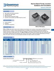
<strong>Coax</strong> <strong>Power</strong> <strong>Dividers</strong><br />
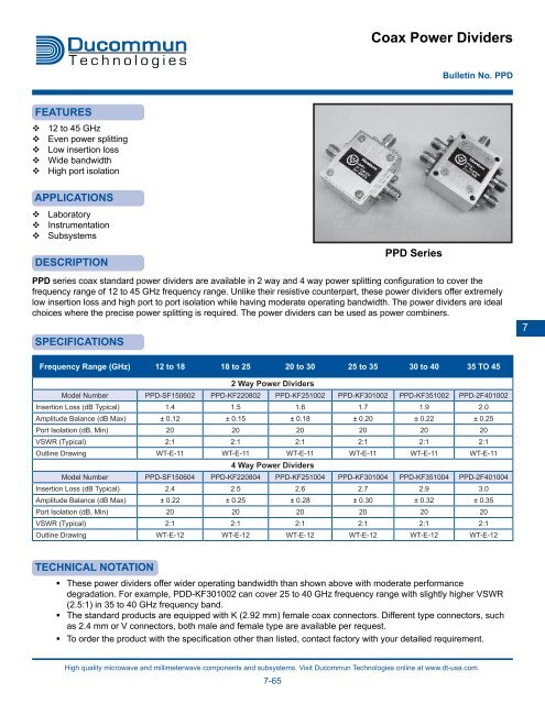
PPD series coax standard power dividers are available in 2 way and 4 way power splitting configuration to cover the<br />
frequency range of 12 to 45 GHz frequency range. Unlike their resistive counterpart, these power dividers offer extremely<br />
low insertion loss and high port to port isolation while having moderate operating bandwidth. The power dividers are ideal<br />
choices where the precise power splitting is required. The power dividers can be used as power combiners.<br />
SPECIFICATIONS<br />
PPD Series<br />
Bulletin No. PPD<br />
Frequency Range (GHz) 12 to 18 18 to 25 20 to 30 25 to 35 30 to 40 35 TO 45<br />
2 Way <strong>Power</strong> <strong>Dividers</strong><br />
Model Number PPD-SF150602 PPD-KF220802 PPD-KF251002 PPD-KF301002 PPD-KF351002 PPD-2F401002<br />
Insertion Loss (dB Typical) 1.4 1.5 1.6 1.7 1.9 2.0<br />
Amplitude Balance (dB Max) ± 0.12 ± 0.15 ± 0.18 ± 0.20 ± 0.22 ± 0.25<br />
Port Isolation (dB, Min) 20 20 20 20 20 20<br />
VSWR (Typical) 2:1 2:1 2:1 2:1 2:1 2:1<br />
Outline Drawing WT-E-11 WT-E-11 WT-E-11 WT-E-11 WT-E-11 WT-E-11<br />
4 Way <strong>Power</strong> <strong>Dividers</strong><br />
Model Number PPD-SF150604 PPD-KF220804 PPD-KF251004 PPD-KF301004 PPD-KF351004 PPD-2F401004<br />
Insertion Loss (dB Typical) 2.4 2.5 2.6 2.7 2.9 3.0<br />
Amplitude Balance (dB Max) ± 0.22 ± 0.25 ± 0.28 ± 0.30 ± 0.32 ± 0.35<br />
Port Isolation (dB, Min) 20 20 20 20 20 20<br />
VSWR (Typical) 2:1 2:1 2:1 2:1 2:1 2:1<br />
Outline Drawing WT-E-12 WT-E-12 WT-E-12 WT-E-12 WT-E-12 WT-E-12<br />
TECHNICAL NOTATION<br />
� These power dividers offer wider operating bandwidth than shown above with moderate performance<br />
degradation. For example, PDD-KF301002 can cover 25 to 40 GHz frequency range with slightly higher VSWR<br />
(2.5:1) in 35 to 40 GHz frequency band.<br />
� The standard products are equipped with K (2.92 mm) female coax connectors. Different type connectors, such<br />
as 2.4 mm or V connectors, both male and female type are available per request.<br />
� To order the product with the specification other than listed, contact factory with your detailed requirement.<br />
7
WT-E-1<br />
4-40 x 0.25 DP<br />
4 PLS<br />
WT-E-3<br />
WT-E-5<br />
COAXIAL CONNECTOR<br />
WR-15 WAVEGUIDE<br />
W/UG385/U FLANGE<br />
High Pass<br />
WAVEGUIDE W/FLANGE<br />
4 PLS<br />
WAVEGUIDE W/FLANGE<br />
2 PLS<br />
WiseWave<br />
M/N: XXXXX<br />
S/N: XXXXX<br />
D/C: XX/XX<br />
Dimensions are in inches<br />
Dimensions are in inches<br />
NOTES:<br />
BOTH MALE AND FEMALE COAXIAL CONNECTORS ARE AVAILABLE FOR ALL BANDS<br />
Dimensions are in inches<br />
Passive Component Outline Drawings #1<br />
High quality microwave and millimeterwave components and subsystems. Visit Ducommun Technologies online at www.dt-usa.com.<br />
7-77<br />
WT-E-2<br />
WT-E-4<br />
WT-E-6<br />
WAVEGUIDE W/FLANGE<br />
2 PLS<br />
WAVEGUIDE W/FLANGE<br />
Low Pass<br />
WAVEGUIDE W/FLANGE<br />
Dimensions are in inches<br />
Dimensions are in inches<br />
Dimensions are in inches<br />
The flange pattern shown is for illustration purpose. Refer to Technical Reference Section for flange pattern details. The outline<br />
drawings shown are standard versions. Contact factory for your specific package requirements.<br />
7
WT-E-7<br />
WT-E-9<br />
WT-E-11<br />
WAVEGUIDE W/FLANGE<br />
3 PLS<br />
WAVEGUIDE W/FLANCE<br />
3 PLS<br />
WiseWave<br />
M/N: XXXXX<br />
S/N: XXXXX<br />
D/C: XX/XX<br />
4-40 x 0.20 DP<br />
4 PLS<br />
Dimensions are in inches<br />
Dimensions are in inches<br />
Dimensions are in inches<br />
Passive Component Outline Drawings #2<br />
High quality microwave and millimeterwave components and subsystems. Visit Ducommun Technologies online at www.dt-usa.com.<br />
7-78<br />
WT-E-8<br />
WT-E-10<br />
WT-E-12<br />
WAVEGUIDE W/FLANGE, 3 PLS<br />
M/N: XXXXX<br />
S/N: XXXXX<br />
D/C: XX/XX<br />
WiseWave<br />
WAVEGUIDE W/FLANGE<br />
3 PLS<br />
0.096 DIA x THRU, 4 PLS<br />
Dimensions are in inches<br />
Dimensions are in inches<br />
Dimensions are in inches<br />
The flange pattern shown is for illustration purpose. Refer to Technical Reference Section for flange pattern details.<br />
The outline drawings shown are standard versions. Contact factory for your specific package requirements.