HEAD acoustics GmbH MFE III.1 (Code 6201) MFE III.2 (Code 6202)
HEAD acoustics GmbH MFE III.1 (Code 6201) MFE III.2 (Code 6202)
HEAD acoustics GmbH MFE III.1 (Code 6201) MFE III.2 (Code 6202)

You also want an ePaper? Increase the reach of your titles
YUMPU automatically turns print PDFs into web optimized ePapers that Google loves.
<strong>HEAD</strong> <strong>acoustics</strong> <strong>GmbH</strong> DATA SHEET<br />
Ebertstraße 30a<br />
D-52134 Herzogenrath<br />
Tel: +49 (0)2407-577-0<br />
Fax: +49 (0)2407-577-99<br />
E-mail: telecom@head-<strong>acoustics</strong>.de<br />
WEB: www.head-<strong>acoustics</strong>.de<br />
DESCRIPTION<br />
<strong>MFE</strong> III includes 2 input channels and 2<br />
output channels for both balanced and<br />
unbalanced operation. It is possible to<br />
switch between input and output. All channels<br />
can be independently amplified.<br />
For connection of an artificial ear or mouth<br />
(both of which are incorporated in the<br />
Artificial Head Measuring System HMS<br />
II.3) a microphone preamplifier, a mouth<br />
amplifier and an equalizer for equalization<br />
of mouth signals are incorporated.<br />
The equalizer provides two equalization<br />
modes for transfer function compensation<br />
for the artificial mouth. Equalization can<br />
be adjusted to the individual requirements<br />
of the client.<br />
10.08 D<strong>6201</strong>e3 Subject to change<br />
Telephone terminal devices are connected<br />
at terminal I/O. Supply voltages are<br />
provided by the international feeding<br />
bridge A. A broad range of adjustment is<br />
available for voltage, inductance, capacitance<br />
and interior impedance.<br />
The line amplifier allows amplification of<br />
test signals.<br />
Simulation of actual transmission paths is<br />
achieved via transmission lines of various<br />
dimensions including a range of line terminations.<br />
A range of line simulations is available<br />
(e.g. Germany, Switzerland, North<br />
America ...).<br />
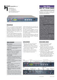
<strong>MFE</strong> <strong>III.1</strong> (<strong>Code</strong> <strong>6201</strong>)<br />
<strong>MFE</strong> <strong>III.2</strong> (<strong>Code</strong> <strong>6202</strong>)<br />
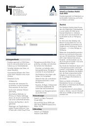
Telecom Measurement Frontend<br />
Frontend for measurement data capture of<br />
analog telephone equipment with ACQUA<br />
Overview<br />
The Frontends <strong>MFE</strong> II/III/IV/V provide the<br />
connecting link between measurement<br />
data capture (via the Artificial Head Measuring<br />
System HMS II.3) and digital analysis<br />
with the ADVANCED COMMUNICATION QUAL-<br />
ITY ANALYSIS System ACQUA.<br />
Via the Frontends, ACQUA is able to<br />
automatically complete standard measurements<br />
(ITU-T/ETSI ...), measurements<br />
to <strong>HEAD</strong> <strong>acoustics</strong> standards, and also<br />
user-defined measurements and measurement<br />
sequences. Configuration of the<br />
Frontends for data capture is fully computer-supported<br />
in ACQUA.<br />
<strong>MFE</strong> III finds application in dual-channel<br />
measurement of analog telephone equipment<br />
in the sending and receiving direction,<br />
and also duplex operation testing.<br />
<strong>MFE</strong> III incorporates the electronics for<br />
operation of analog telephone terminal<br />
devices and the measurement of such<br />
devices for a range of transmission paths.<br />
<strong>MFE</strong> <strong>III.1</strong>: Version for Europe<br />
<strong>MFE</strong> <strong>III.2</strong>: Version for North America<br />
Simulation of a terminal device at the telephone<br />
end is achieved via a holding circuit<br />
and an additional signal line termination<br />
(e.g. appropriate for testing metering<br />
devices).
Advanced<br />
Communication<br />
Quality<br />
Analysis<br />
HMS II.3<br />
Artificial Head<br />
Measur ement<br />
System<br />
COMPONENTS<br />
V.24<br />
dig. out<br />
AES/EBU<br />
dig. in<br />
• Dual-channel input module and<br />
dual-channel output module -<br />
impedance:<br />
- balanced: 600 Ohm, ZR (complex<br />
impedance to FTZ 1TR2), (as<br />
option 900 Ohm - US version)<br />
- unbalanced: 100 kOhm (input),<br />
50 Ohm ( output)<br />
• 4 Amplifier modules for the 2 input<br />
and output channels<br />
• Microphone preamplifier<br />
(artificial ear)<br />
• Power amplifier for the artificial<br />
mouth<br />
• Equalizer with 2 selectable<br />
equalizations for the mouth signal<br />
• Digital/analog and analog/digital<br />
converter<br />
- data formats: AES/EBU, IEC<br />
- sampling rates: 32 kHz, 44.1 kHz,<br />
48 kHz<br />
• Processor control for the<br />
configuration from ACQUA<br />
10.08 D<strong>6201</strong>e3 Subject to change<br />
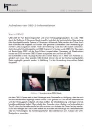
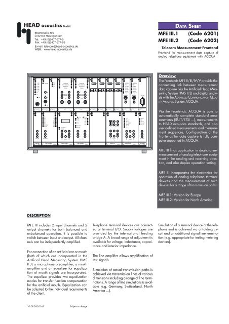
Measurement Frontend<br />
with Line Simulator<br />
A<br />
A<br />
D<br />
D<br />
D<br />
D<br />
A<br />
A<br />
Bridge<br />
Line<br />
terminations<br />
V=<br />
-40 dB<br />
...+30 dB<br />
Feeding<br />
bridge A<br />
• Terminal I/O for connection to<br />
telephone terminal equipment<br />
• International feeding bridge A<br />
(connection for external feeding<br />
resistor or feeding bridge)<br />
• Line amplifier (external output)<br />
• Line simulation Germany (as option<br />
Switzerland, USA) (input/output for<br />
external use of the internal line simulation<br />
or for an external line simulation)<br />
• Line terminations (input/output for<br />
external use of the internal<br />
termination or for an external<br />
termination)<br />
• Holding circuit (input/output for<br />
external use of the internal<br />
termination or for an external<br />
termination)<br />
• Line termination at the telephone end<br />
(input/output for external use of the<br />
internal termination or for an<br />
external termination)<br />
Line<br />
~<br />
simulations<br />
+<br />
-<br />
+<br />
-<br />
ZR balanced<br />
(900 W - USA)<br />
600 W bal.<br />
100k W unbal.<br />
ZR balanced<br />
(900 W - USA)<br />
600 W bal.<br />
600 W bal.<br />
ZR balanced<br />
(900 W - USA)<br />
50 W unbal.<br />
600 W bal.<br />
ZR balanced<br />
(900 W - USA)<br />
Line Amplifier<br />
a<br />
b<br />
art. ear<br />
analog<br />
in<br />
analog<br />
out<br />
art. mouth
STANDARD DELIVERY ITEMS<br />
<strong>MFE</strong> III (<strong>Code</strong> <strong>6201</strong>)<br />
comprises the following components:<br />
• MFH III (<strong>Code</strong> 6280):<br />
Housing for <strong>MFE</strong> III<br />
MPA I.2 (<strong>Code</strong> 6195):<br />
Microphone-preamplifier for <strong>MFE</strong> II/III<br />
with LEMO connector<br />
alternatively:<br />
MPA I.1 (<strong>Code</strong> 6185):<br />
Microphone-preamplifier for <strong>MFE</strong> II/III<br />
with B&K socket<br />
MAM I.1 (<strong>Code</strong> 6186):<br />
Mouth amplifier for <strong>MFE</strong> II/III<br />
MEQ II (<strong>Code</strong> 6194):<br />
<strong>MFE</strong> II/III equalizer<br />
MBI I.1 (<strong>Code</strong> 6188):<br />
Balanced/unbalanced input for <strong>MFE</strong> II/III<br />
(Standard delivery with <strong>MFE</strong> <strong>III.1</strong>)<br />
MBO I.1 (<strong>Code</strong> 6189):<br />
Balanced/unbalanced output for <strong>MFE</strong> II/<br />
III (Standard delivery with <strong>MFE</strong> <strong>III.1</strong>)<br />
AIO II (<strong>Code</strong> 6193):<br />
Amplifier for input/output channels for<br />
<strong>MFE</strong> II/III (4´)<br />
ADU I.1 (<strong>Code</strong> 6183):<br />
A/D unit for <strong>MFE</strong> I/II/III<br />
DAU I.1 (<strong>Code</strong> 6182):<br />
D/A unit for <strong>MFE</strong> I/II/III<br />
CPU (<strong>Code</strong> 6184):<br />
CPU for <strong>MFE</strong> I/II/III/IV/V<br />
MLA I.1 (<strong>Code</strong> 6286):<br />
Line amplifier<br />
Generator<br />
and Analyzer<br />
Diffuse<br />
Field<br />
RS232<br />
AES / EBU<br />
(digital)<br />
IEEE 488<br />
or RS232<br />
10.08 D<strong>6201</strong>e3 Subject to change<br />
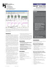
Analog<br />
Frontend<br />
including internal<br />
- feeding bridge,<br />
- line simulation,<br />
- line termination<br />
MLT III (<strong>Code</strong> 6297):<br />
Line terminations (international)<br />
MFA III (<strong>Code</strong> 6296):<br />
International feeding bridge A<br />
MLS I.1 (<strong>Code</strong> 6282):<br />
Line simulation German standard<br />
(Standard delivery with <strong>MFE</strong> <strong>III.1</strong>)<br />
MTI II.1 (<strong>Code</strong> 6295):<br />
Terminal I/O<br />
MHC I.1 (<strong>Code</strong> 6284):<br />
Holding circuit German standard<br />
MMT (<strong>Code</strong> 6287):<br />
Termination impedances to German standard<br />
CLD II.1 (<strong>Code</strong> 6071):<br />
Cable RS 232,<br />
D-Sub 9 pin ↔ D-Sub 25 pin, 3 m<br />
CCC I.1 (<strong>Code</strong> 4174):<br />
Cable cinch ↔ cinch, 1m (2 x)<br />
PCC I.9x (<strong>Code</strong> 997x):<br />
Mains cable (to local specification)<br />
MFD I (<strong>Code</strong> 6059):<br />
User’s manual <strong>MFE</strong> I/II/III/IV/V<br />
CBA I (<strong>Code</strong> 6077):<br />
Cable adaptor BNC ↔ BNC with<br />
integrated capacitor (2 x)<br />
OPTIONS<br />
LSS I.1 (<strong>Code</strong> 6289):<br />
Line simulation Switzerland standard<br />
MLU I (<strong>Code</strong> 6293):<br />
Line simulation USA standard<br />
(Standard delivery with <strong>MFE</strong> <strong>III.2</strong>)<br />
<strong>MFE</strong> III.x<br />
(analog)<br />
External Devices<br />
(as option):<br />
ext. feeding bridge<br />
ext. line simulation<br />
ext. termination<br />
Background<br />
Noise<br />
HAE-BGN<br />
(a/b) TAE<br />
Mic<br />
LS<br />
MBI II.1 (<strong>Code</strong> 6173):<br />
Balanced/unbalanced input<br />
(Standard delivery with <strong>MFE</strong> <strong>III.2</strong>)<br />
MBO II.1 (<strong>Code</strong> 6174):<br />
Balanced/unbalanced output<br />
(Standard delivery with <strong>MFE</strong> <strong>III.2</strong>)<br />
CTD II (<strong>Code</strong> 6078):<br />
Cable Telecom plug ↔ D-Sub 9-pol.<br />
(for GSM)<br />
alternatively:<br />
CTD III (<strong>Code</strong> 6081):<br />
Cable Telecom plug ↔ D-Sub 9-pol.<br />
(for CDMA)<br />
ACCESSORIES<br />
HMS II.3 (<strong>Code</strong> 1230):<br />
Artificial <strong>HEAD</strong> Measurement System incl.<br />
ear simulation and artificial mouth<br />
ACOPT 22 (<strong>Code</strong> 6847):<br />
Option ES 203 021 - Basic Attachment<br />
Requirements for Analog Terminals<br />
HMS II.3 &<br />
HHP III<br />
Ear<br />
Simulator<br />
Mouth<br />
Simulator<br />
Test Head
Technical Data<br />
D/A Converter<br />
Quantization: 20 bits<br />
Sampling rate: 32 kHz, 44.1 kHz, 48 kHz<br />
Inputs: AES/EBU, IEC<br />
Oversampling: 8-fold<br />
Deemphasis: 15 µs/50 µs (automatic)<br />
Nom. output voltage: 1 V<br />
Max. output voltage: 2 V<br />
S/N ratio: > 100 dB (at full modulation)<br />
Dynamic range: > 96 dB<br />
A/D Converter<br />
Quantization: 18 bits<br />
Sampling rate: 32 kHz, 44.1 kHz, 48 kHz<br />
Outputs: AES/EBU, IEC<br />
Oversampling: 64-fold<br />
Preemphasis: 15 µs/50 µs (switchable)<br />
Nom. input voltage: 1 V<br />
Max. input voltage: 2 V<br />
S/N ratio: > 93 dB (at full modulation)<br />
Dynamic range: > 93 dB<br />
Analog Inputs and Outputs<br />
Sockets: BNC, unbalanced; banana-type,<br />
balanced<br />
Amplification: -40 dB - +30 dB, adjustable in<br />
steps of 1 dB<br />
Max. deviation of amplification: -30 dB - +30 dB: 0.03 dB<br />
Inputs<br />
Impedance: 100 kΩ unbalanced, 600 Ω<br />
balanced, ZR balanced<br />
(900 Ω balanced - version for<br />
North America)<br />
Transmission range: 20 Hz - 20 kHz, ± 0.1dB<br />
Nom. input voltage: 1 V<br />
S/N ratio: > 90 dB (at full modulation)<br />
Dynamic range: > 90 dB<br />
Cross-talk attenuation: > 80 dB (1 kHz at nom. level)<br />
Distortion factor: < 0.01 % (1 kHz at nom. level)<br />
Outputs<br />
Impedance: 50 Ω unbalanced, 600 Ω<br />
balanced, ZR balanced<br />
(900 Ω balanced - version for<br />
North America)<br />
Transmission range: 20 Hz - 20 kHz (± 0.1 dB)<br />
S/N ratio: > 100 dB (at full modulation)<br />
Dynamic range: > 90 dB<br />
Cross-talk attenuation: > 80 dB (1 kHz at nom. level)<br />
Distortion factor: < 0.01 % (1 kHz at nom. level)<br />
Microphone input<br />
Transmission range: 20 Hz - 10 kHz (± 0.1dB)<br />
Calibration: using conventional measurement<br />
microphones to 0 dB Pa = 0 dBV at<br />
position 0 dB<br />
Level adjustment: 50 dB to 0 dB, adjustable in steps<br />
of 10 dB ± 0.05 dB<br />
High-pass: activatable, fg = 22.4 Hz<br />
S/N ratio: > 80 dB (at full modulation)<br />
Dynamic range: > 80 dB<br />
Distortion factor: < 0.01 % (1 kHz at nom. level)<br />
Power amplifier for artificial mouth<br />
Max. output power 10 W at 4 Ω<br />
Transmission range: 20 Hz - 20 kHz<br />
Dynamic range: > 80 dB<br />
Distortion factor: < 0.2 %,<br />
Equalization 2 equalization modes selectable<br />
10.08 D<strong>6201</strong>e3 Subject to change<br />
Line simulation<br />
(Europe) to DTB-Telekom Specification FTZ 1TR2<br />
Main station line simulation<br />
0.4 mm dia.: 0.4 km, 1 km, 2 km, 3 km, 4 km<br />
0.6 mm dia. 3 km, 6 km<br />
Extension line simulation<br />
Line simulation<br />
(Northern America) to specification TIA/EIA 470B<br />
Lengths of lines: 3 kft, 6 kft, 9 kft, 12 kft, 15 kft<br />
external line simulation can be connected<br />
Line terminations<br />
Impedance 600 Ω, 100 Ω, ZR (ZV24b/ZEURO),<br />
ZV24/ZEURO_a, ZV24/ZEURO_c,<br />
1500 Ω<br />
additionally: ZEURO_b / (TBR 21), 900 Ω<br />
as option, possibility of 6 further impedances<br />
external impedance can be connected<br />
International feeding bridge A<br />
C = 0µF - 104µ ΔC = 2µF<br />
Feeding resistor unbalanced 0 - 80 kΩ ΔR = 10 Ω<br />
Supply voltage 20 V ... 65 V ΔU = 1 V<br />
Feeding current max. 100 mA<br />
Feeding resistor balanced 100 Ω - 850 Ω per feeding branch<br />
ΔR = 50 Ω<br />
Feeding inductivity 1 H, 2 H, 5 H or 10 H per path<br />
Holding circuit:<br />
Resistance 0 Ω, 200 Ω, 300 Ω or external<br />
external holding circuit can be connected<br />
Mains operation: 90 V-120 V / 200 V - 265 V<br />
47-63 Hz<br />
Max. power consumption: 200 W<br />
Environmental conditions<br />
Operating temperature range: 0°C - 40°C, 32°F - 104°F<br />
In-store temperature range: -40°C - 80°C, -40°F - 176°F<br />
Measurements at room<br />
temperature are recommended<br />
Housing<br />
Overall dimensions (W×H×D) 530 mm × 310 mm × 430 mm<br />
Weight: 26 kg<br />
represented by