10-9. TEST POINT DIAGRAM Outdoor controller ... - MyLinkDrive
10-9. TEST POINT DIAGRAM Outdoor controller ... - MyLinkDrive
10-9. TEST POINT DIAGRAM Outdoor controller ... - MyLinkDrive

Create successful ePaper yourself
Turn your PDF publications into a flip-book with our unique Google optimized e-Paper software.
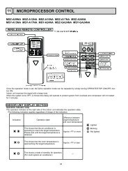
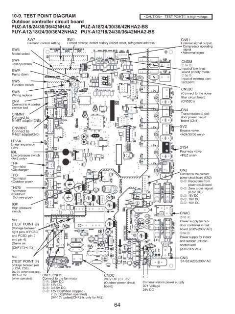
<strong>10</strong>-<strong>9.</strong> <strong>TEST</strong> <strong>POINT</strong> <strong>DIAGRAM</strong><br />
<strong>TEST</strong> <strong>POINT</strong>1 is high voltage.<br />
<strong>Outdoor</strong> <strong>controller</strong> circuit board<br />
PUZ-A18/24/30/36/42NHA2 PUZ-A18/24/30/36/42NHA2-BS<br />
PUY-A12/18/24/30/36/42NHA2 PUY-A12/18/24/30/36/42NHA2-BS<br />
SW6<br />
Model select<br />
SW4<br />
Test operation<br />
SWP<br />
Pump down<br />
SW5<br />
Function switch<br />
SW8<br />
Wiring replace<br />
CNM<br />
Connect to A control<br />
service tool<br />
CNMNT<br />
Connect to<br />
M-NET adapter(CN5)<br />
CNVMNT<br />
Connect to<br />
M-NET adapter(CND)<br />
LEV-A<br />
Linear expansion<br />
valve<br />
63L<br />
Low pressure switch<br />
<br />
TH4<br />
Thermistor<br />
<br />
TH3<br />
Thermistor<br />
<br />
TH7/6<br />
Thermistor<br />
<br />
63H<br />
High pressure<br />
switch<br />
VFG<br />
(<strong>TEST</strong> <strong>POINT</strong> 4)<br />
(Voltage between<br />
right pins of PC5C<br />
and PC5D, pin 3<br />
and pin 4)<br />
(Same as<br />
(CNF17(+)-4(-))<br />
VSP<br />
(<strong>TEST</strong> <strong>POINT</strong> 3)<br />
(Voltage between pins<br />
of C5A, C5B):<br />
DC 0V (when stopped),<br />
DC 1– 6.5V<br />
(when operated)<br />
SW7<br />
Demand control setting<br />
SW1<br />
Forced defrost, detect history record reset, refrigerant address<br />
CNF1, CNF2<br />
Connect to the fan motor<br />
1-4: 280V DC<br />
5-4: 15V DC<br />
6-4: 0-6.5V DC<br />
7-4: 15V DC(When stopped)<br />
7.5V DC(When operated)<br />
(0V-15V pulse)(CNF2 is only for A42)<br />
CNDC<br />
280V DC (1+, 3-)<br />
(<strong>Outdoor</strong> power circuit<br />
board)<br />
64<br />
+ -<br />
Communication power supply<br />
D71 Voltage<br />
24V DC<br />
CN51<br />
External signal output<br />
• Compressor operating<br />
signal<br />
• Abnormal signal<br />
CNDM<br />
1 to 2:<br />
Input of low-level<br />
sound priority mode<br />
1 to 3:<br />
Input of external contact<br />
point<br />
CN52C<br />
(Connect to the noise<br />
filter circuit board<br />
(CN52C))<br />
CN4<br />
Transmission to outdoor<br />
power circuit<br />
board (CN4)<br />
SV2<br />
Bypass valve<br />
<br />
21S4<br />
Four-way valve<br />
<br />
CN2<br />
Connect to the outdoor<br />
power circuit board (CN2)<br />
1-5: Reception from<br />
power circuit board<br />
2-5: Zero cross signal<br />
(0-5V DC)<br />
3,4: 18V DC<br />
6-5: 16V DC<br />
7-5: 16V DC<br />
CNAC<br />
2 to 4:<br />
Power supply for outdoor<br />
<strong>controller</strong> circuit<br />
board (208V-230V AC)<br />
1 to 3:<br />
Power supply for indoor<br />
and outdoor unit connection<br />
wire<br />
(208/230V AC)<br />
CNS<br />
S1-S2:A208/230V AC
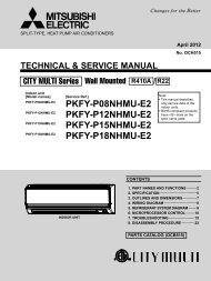
<strong>Outdoor</strong> noise filter circuit board<br />
PUZ-A18NHA2 PUZ-A18NHA2-BS<br />
PUY-A12/18NHA2 PUY-A12/18NHA2-BS<br />
LI, NI<br />
Voltage of 208/230V AC is input.<br />
(Connect to the terminal block(TB1))<br />
E3<br />
Connect to the earth<br />
CNAC1, CNAC2<br />
208/230V AC<br />
(Connect to the<br />
outdoor <strong>controller</strong><br />
circuit board<br />
(CNAC))<br />
65<br />
EI<br />
Connect to the earth<br />
CN52C<br />
52C relay signal<br />
(Connect to the<br />
outdoor <strong>controller</strong><br />
circuit board<br />
(CN52C))<br />
E2<br />
Connect to the earth<br />
CN5<br />
Primary current<br />
(Connect to the<br />
outdoor power<br />
circuit board<br />
(CN5))<br />
LO, NO<br />
Voltage of<br />
208/230V AC is<br />
output.<br />
(Connect to the ACL)
<strong>Outdoor</strong> noise filter circuit board<br />
PUZ-A24NHA2 PUZ-A24NHA2-BS<br />
PUY-A24NHA2 PUY-A24NHA2-BS<br />
EI, E2<br />
Connect to the earth<br />
CNAC1, CNAC2<br />
208/230V AC<br />
(Connect to the<br />
outdoor <strong>controller</strong><br />
circuit board<br />
(CNAC))<br />
CN5<br />
Primary current<br />
(Connect to the<br />
outdoor power<br />
circuit board<br />
(CN5))<br />
CN52C<br />
52C relay signal<br />
(Connect to the<br />
outdoor <strong>controller</strong><br />
circuit board<br />
(CN52C))<br />
LO, NO<br />
Voltage of 208/230V AC is output.<br />
(Connect ACL)<br />
66<br />
E3<br />
Connect to<br />
the earth
<strong>Outdoor</strong> noise filter circuit board<br />
PUZ-A30/36/42NHA2 PUZ-A30/36/42NHA2-BS<br />
PUY-A30/36/42NHA2 PUY-A30/36/42NHA2-BS<br />
RS1<br />
CNAC1, CNAC2<br />
208/230V AC<br />
(Connect to the<br />
outdoor <strong>controller</strong><br />
circuit board<br />
(CNAC))<br />
EI<br />
Connect to<br />
the earth<br />
LI, NI<br />
Voltage of 208/230V AC is input.(Connect to the terminal block(TB1))<br />
67<br />
CN52C<br />
52C driving signal (Connect to<br />
the outdoor <strong>controller</strong> circuit<br />
board(CN52C))<br />
LO, NO<br />
Voltage of 208/230V AC is output<br />
(Connect to the outdoor power<br />
circuit board (TABS, TABT))<br />
E2<br />
Connect to the earth<br />
CN5<br />
Primary current<br />
(Connect to the outdoor power<br />
circuit board (CN5))
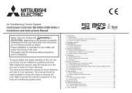
<strong>Outdoor</strong> power circuit board<br />
PUZ-A18NHA2<br />
PUZ-A18NHA2-BS<br />
PUY-A12/18NHA2<br />
PUY-A12/18NHA2-BS<br />
LD1-LD2<br />
280-380V DC<br />
Connect to<br />
the outdoor<br />
<strong>controller</strong><br />
circuit board<br />
(CNDC)<br />
CN2<br />
Connect to the outdoor <strong>controller</strong> circuit board (CN2)<br />
1-5:<strong>Outdoor</strong> power circuit board ➔ Transmitting signal<br />
to the outdoor <strong>controller</strong> circuit board (0-5V DC)<br />
2-5: Zero cross signal (0-5V DC)<br />
3-4: Not used<br />
6-5: 16V DC<br />
7-5: 16V DC<br />
[<br />
1, 2, 6, 7 : +<br />
5 : – ]<br />
Brief check of DIP-IPM and DIP-PFC<br />
W Usually, they are in a state of being short-circuited if they are broken.<br />
Measure the resistance in the following points (connectors, etc.). If they<br />
are short-circuited, it means that they are broken.<br />
1. Check of DIP-IPM<br />
P-U, P-V, P-W, N-U, N-V, N-W<br />
2. Check of DIP-PFC<br />
P-R, P-S, R-N, S-N<br />
R, S<br />
Connect to the ACL<br />
208/230V AC<br />
CN3<br />
Thermistor<br />
<br />
(TH8)<br />
68<br />
U, V, W<br />
Connect to the compressor (MC)<br />
Voltage among phases: 5V to 180V AC<br />
CN4<br />
Connect from the<br />
outdoor <strong>controller</strong><br />
circuit board<br />
(CN4)<br />
DIP-PFC<br />
LD9<br />
Connect to<br />
the earth<br />
Only A24<br />
DIP-IPM<br />
CN5<br />
Primary current detection<br />
(Connect to the outdoor<br />
noise filter circuit board<br />
(CN5))
<strong>Outdoor</strong> power circuit board<br />
PUZ-A30/36/42NHA2<br />
PUZ-A30/36/42NHA2-BS<br />
PUY-A30/36/42NHA2<br />
PUY-A30/36/42NHA2-BS<br />
CN2<br />
Connect to the outdoor <strong>controller</strong> circuit board<br />
(CN2)<br />
1-5:Transmitting signal to the outdoor<br />
<strong>controller</strong> circuit board (0~5V DC)<br />
2-5:Zero cross signal (0~5V DC)<br />
3,4:18V DC<br />
6-5:16V DC<br />
7-5:16V DC<br />
CNAF<br />
Connect to ACTM<br />
CN3<br />
Thermistor (TH8)<br />
<br />
CN5<br />
Detection of primary<br />
current<br />
Connect to the<br />
outdoor noise filter<br />
circuit board (CN5)<br />
CN4<br />
Connect to the<br />
outdoor <strong>controller</strong><br />
circuit board<br />
(CN4)<br />
TABP2/SC-P2<br />
Connect to<br />
ACTM<br />
TABN<br />
Connect to the<br />
smoothing capacitor<br />
CB –<br />
(A42N only)<br />
TABP<br />
Connect to the<br />
smoothing capacitor<br />
CB +<br />
(A42N only)<br />
Brief check of POWER MODULE<br />
W Usually, they are in a state of being short-circuited if they are broken.<br />
Measure the resistance in the following points (connectors, etc.).<br />
If they are short-circuited, it means that they are broken.<br />
1. Check of diode bridge<br />
TABP1-TABS, TABN1-TABS, TABP1-TABT,TABN1-TABT<br />
2. Check of DIP-IPM<br />
P-U, P-V, P-W, N-U, N-V, N-W<br />
69<br />
DIP-IPM<br />
TABU/V/W<br />
Connect to the compressor (MC)<br />
Voltage among phases:<strong>10</strong>V~180V AC<br />
CNDC<br />
280-380V DC (1+, 3–)<br />
Connect to the outdoor<br />
<strong>controller</strong> circuit board<br />
TABN2<br />
Connect to ACTM<br />
TABS/TABT<br />
Connect to the<br />
outdoor noise<br />
filter circuit<br />
board<br />
Voltage among<br />
phases:<br />
208/230V AC<br />
TABP1<br />
Connect to 52C<br />
TABN1<br />
Connect to<br />
ACTM
Active filter module<br />
PUZ-A30/36/42NHA2 PUZ-A30/36/42NHA2-BS<br />
PUY-A30/36/42NHA2 PUY-A30/36/42NHA2-BS<br />
L1, L2<br />
Connect to<br />
the DCL<br />
(Reactor)<br />
DCL<br />
L1 L2 ACTM<br />
70<br />
P<br />
Connect to the outdoor power circuit board<br />
(TABP2)<br />
N1<br />
Non-connect<br />
Upper side Lower side<br />
+<br />
Connect to<br />
the outdoor<br />
power circuit<br />
board<br />
(TABP1)<br />
–<br />
Connect to the outdoor power circuit board<br />
(TABN1)<br />
Connection and internal circuit diagram<br />
(+)<br />
(–)<br />
Connect to the outdoor power circuit<br />
board (CNAF)<br />
1 : GND<br />
2-1 : 15V DC<br />
3-1 : Control signal<br />
4, 5 : Not used<br />
6-1 : Control signal<br />
lo<br />
Connect to the outdoor power circuit board<br />
(TABN2)<br />
P<br />
N1<br />
N2<br />
Io<br />
+<br />
Load<br />
N2<br />
Non-connect