ZW37-40.5 Model Outdoor AC HV Vacuum Circuit Breaker ZW37 ...
ZW37-40.5 Model Outdoor AC HV Vacuum Circuit Breaker ZW37 ...
ZW37-40.5 Model Outdoor AC HV Vacuum Circuit Breaker ZW37 ...

Create successful ePaper yourself
Turn your PDF publications into a flip-book with our unique Google optimized e-Paper software.
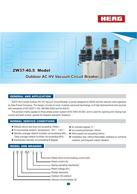
<strong>ZW37</strong>-<strong>40.5</strong> <strong>Model</strong><br />
<strong>Outdoor</strong> <strong>AC</strong> <strong>HV</strong> <strong>Vacuum</strong> <strong>Circuit</strong> <strong>Breaker</strong><br />
GENERAL AND APPLICATION<br />
<strong>ZW37</strong>-<strong>40.5</strong> model <strong>Outdoor</strong> <strong>AC</strong> <strong>HV</strong> <strong>Vacuum</strong> <strong>Circuit</strong> <strong>Breaker</strong> is jointly designed by HEAG and the relevant units organized<br />
by Sate Power Company. The design concept is novel. It adopts advanced technology, is of high technical level and accords<br />
with standards of IEC-62271-100, GB1984-2003 and DL403-91.<br />
The product mainly applies to three phase power system of <strong>AC</strong> 50Hz <strong>40.5</strong>kV, and is used for opening and closing load<br />
current and fault current, special for frequent operation locations.<br />
NORMAL SERVICE CONDITIONS<br />
Altitude above sea level not exceeding 1000m ;<br />
Environmental ambient temperature: -35 +40 ;<br />
Monthly average relative humidity not exceeding 90%,<br />
Daily average relative humidity not exceeding 95%;<br />
Earthquake intensity not exceeding 8 degree;<br />
MODEL AND MEANING<br />
Z W 37 - <strong>40.5</strong> / T -<br />
Rated short-circuit breaking current (kA)<br />
Rated current (A)<br />
Spring operating mechanism<br />
Rated voltage (kV)<br />
Design sequence<br />
<strong>Outdoor</strong> (W-outdoor)<br />
<strong>Vacuum</strong> circuit breaker (Z)<br />
1<br />
Air polluted degree: ;<br />
Ice covering thickness: 20mm;<br />
Wind speed not exceeding 34m/s;<br />
Installation site: without flammable, explosive or corrosive<br />
material, and frequent violent vibration.
PRODUCT FEATURE<br />
General structure: A supporting porcelain insulator with an epoxy bushing. The upper is an epoxy bushing with vacuum<br />
interrupter inside, the lower is a supporting porcelain insulator with an insulation drawbar and a linkage rod. Three poles<br />
of supporting porcelain insulators are together mounted on a mechanism box, and the movable terminal of interrupter is<br />
linked with the output shaft through the insulation drawbar.<br />
The enclosure of interrupter is outdoor epoxy resin and is whole sealed using introduced foreign advanced technology,<br />
which has reached the international advance level and is the first domestic creation. It has advantages of anti-condensation,<br />
ant-ageing, outdoor high temperature and freezing resistant, so as to avoid a series of problems caused by gas or oil<br />
charging and has basically reached the level of maintenance-free.<br />
The movable terminal of interrupter is vertically linked with the output shaft through the insulation drawbar and vertically<br />
moves, which is safe, reliable and convenient for commissioning and maintenance.<br />
The mechanism and linkage rod are mounted inside a waterproof box, where a heater can be installed to prevent the<br />
electric control components from moisture.<br />
The product can be allocated with various ratios of current transformers for measurement and protection. The user can<br />
choose the right CT according to the requirement.<br />
The product is of novel structure, simple and reliable, small volume and light weight, and is convenient for mounting.<br />
It can be allocated with a control terminal interface to be used for automated distribution network and unmanned substation.<br />
MAIN TECHNICAL PARAMETERS<br />
5.1 Main technical parameters of circuit breaker table 1<br />
No<br />
Items<br />
Unit<br />
Data<br />
1 Rated voltage<br />
kV<br />
<strong>40.5</strong><br />
2 Rated current<br />
A<br />
630, 1250, 1600, 2000<br />
3 Rated short-circuit breaking current<br />
20<br />
25<br />
31.5<br />
4<br />
5<br />
Rated short-circuit making current<br />
Rated short-time withstand current<br />
peak<br />
kA<br />
50<br />
20<br />
63<br />
25<br />
80<br />
31.5<br />
6 Rated peak withstand current<br />
50<br />
63<br />
80<br />
7 Rated short circuit duration<br />
s<br />
4<br />
8<br />
Rated<br />
insulation<br />
level<br />
1min P.F. withstand voltage<br />
lightning impulse withstand voltage peak<br />
kV<br />
95<br />
185<br />
9 Rated operating sequence<br />
O 0.3s CO 180s CO<br />
10<br />
11<br />
Breaking times of rated short-circuit breaking current<br />
Mechanical life<br />
time<br />
20<br />
10000<br />
12<br />
13<br />
Rated operating voltage<br />
Rated voltage of auxiliary circuit<br />
V<br />
V<br />
220 (DC <strong>AC</strong>)<br />
220 (DC <strong>AC</strong>)<br />
5.2 Main mechanical parameters of circuit breaker table 2<br />
No Items Unit Data<br />
1<br />
2<br />
Open distance of contact<br />
Contacting travel of contact<br />
mm<br />
20<br />
3<br />
2<br />
1<br />
3<br />
4<br />
Average closing speed<br />
Average opening speed<br />
m/s<br />
0.8<br />
1.8<br />
0.3<br />
0.3<br />
5 Closing time<br />
40 100<br />
6<br />
7<br />
Opening time<br />
Closing/Opening time<br />
Ms<br />
20 60<br />
65<br />
8 Three phase opening asynchronism<br />
2<br />
2
continued table 2<br />
No Items Unit Data<br />
9<br />
10<br />
Three phase closing asynchronism<br />
Bounce time of contact closing<br />
ms<br />
2<br />
5<br />
11 <strong>Circuit</strong> resistance of each phase<br />
60<br />
12 Contact self-closing pressure N<br />
180 50<br />
13 Center distance between phases mm<br />
700 5<br />
PRODUCT STRUCTURE<br />
6.1 The structure and installation dimension of <strong>ZW37</strong>-<strong>40.5</strong> model vacuum circuit breaker refers to Fig. 3.<br />
6.2 The circuit breaker consists of vacuum interrupter enclosed by epoxy resin, supporting porcelain bushing, base, operating<br />
mechanism and transmission components. Thereinto, upper wiring block, fixed conductive rod and movable conductive rod of<br />
interrupter, soft links and lower wiring block compose a conductive circuit. The operating mechanism installed on the base operates<br />
the movable conductive rod of interrupter through the transmission components which consists of crutch arm, long-axis linkage<br />
rod and insulation drawbar.<br />
6.3 The vacuum interrupter is casted and whole sealed with high-performance epoxy resin and the shape adopts big creepage<br />
distance umbrella skirts structure with advantages of anti-condensation, anti-aging, outdoor high temperature and freezing<br />
resistant. It directly connects with the supporting porcelain bushing without the liquid or gas insulation medium filled inside .<br />
WORKING PRINCIPLE<br />
The operating mechanism of spring energy storage connects with the base with 8-M12 bolt, and the working principle is as<br />
follows (see Figure 1):<br />
7.1 Electrical energy storage: The mechanism is a two-step gear speed-down system. The motor transmits input torque to<br />
the driving pawl of the big gear through the small gear of input shaft after two-step deceleration, and the driving pawl drives the<br />
feeding bushing connected with energy storage shaft to make the crutch arm lengthen the closing spring, so as to realize energy<br />
storage. After energy is stored, the rocker arm pushes the micro-switch to cut off the power, and the clutch wheel simultaneously<br />
puts the driving pawl up to be away from the driving block, thereby to ensure that the energy storage mechanical system will<br />
not be destroyed under the effect of inertia force.<br />
7.2 Manual energy storage: Insert the manual energy storage handle into the hole of the energy storage rocker arm, then<br />
swing up and down by about 35 , drive the pawl wheel through the pawl of rocker arm and make the energy storage shaft<br />
rotate to realize closing energy storage.<br />
7.3 Closing operation: When the mechanism is in opening & energy stored state (Figure 1A), the closing spring will keep<br />
this state under the effect of the detent and half shaft. When the closing tripping half shaft rotates clockwise by about 20<br />
to the tripping position, the closing detent will rotate clockwise under the force effect of the closing spring, then the closing spring<br />
will quickly release the stored energy and the closing cam will rotate clockwise, so as to complete the closing operation.<br />
7.4 Opening operation: The mechanism keeps the closing state under the effect of the half shaft and the withhold plate of<br />
5-linkage mechanism. When the opening half shaft rotates anti-clockwise by about 20 , the withhold plate will rotate anticlockwise,<br />
then the balance state of the linkage mechanism is released and it will move to the opening position under the load<br />
force effect of circuit breaker.<br />
7.5 In Figure 1C & 1D,<br />
1) When the mechanism is in energy non-stored state, if NC contacts of travel switch are connected, the energy storage<br />
switch K will close and the power of motor will be on, then the closing spring will start storing energy. After the energy is stored,<br />
NC contacts of micro-switch will open and cut off the power of motor to make it stop rotating. The micro-switch has another pair<br />
of NO contacts using for energy storage signal indicator YD.<br />
2) After the closing spring finishes storing energy, if the mechanism is open, it will carry out closing operation as long as the<br />
closing button HA closes and the closing coil HQ is electrified. Once the closing operation is completed, NC contact of auxiliary<br />
3
switch will open and cut off the power of closing electromagnet.<br />
3) After the mechanism is closed, if NO contact of auxiliary switch closes, the mechanism will carry out the opening operation<br />
as long as the opening button FA closes and the opening coil FQ is electrified. Once the opening operation is completed, NO<br />
contact of auxiliary switch will open and cut off the power of the opening electromagnet coil. The auxiliary switch has other<br />
groups of NO/NC contacts using for the closing/opening indications HD, LD.<br />
Opening half shaft -10<br />
Holdwith plate - 9<br />
Closing half shaft - 5<br />
Cam-3<br />
7- Output regulation crank<br />
8- Output shaft<br />
6- Connecting plate<br />
4- Cam<br />
1- Closing detent<br />
2- Cleat<br />
Fig. 1-A Opening & energy stored state Fig. 1-B Closing & energy stored state<br />
Fig. 1-C Opening & energy non-stored state Fig. 1-D Closing & energy non-stored state<br />
PRODUCT INSTALLATION, OPERATION AND DEBUGGING<br />
8.1 Inspection:<br />
1) After receiving the equipment, the user shall check if the appearance is good, if the porcelain bushing and epoxy resin<br />
are broken or have the cracks, and if the mechanism box is good.<br />
2) Check if the technical data on the name -plate accord with the ordering requirements, if the attached files are complete,<br />
and if the spare parts and accessories accord with the packing list.<br />
8.2 Debugging<br />
The circuit breaker has been strictly tested before leaving factory, the mechanical parameters satisfy the data listed in<br />
table 2 (details as per Factory Test Report). The user can carry out debugging or detection as follows:<br />
4
Linkage rod<br />
Fixed contact<br />
Movable contact<br />
M14 nut<br />
M14 nut<br />
Fig. 2 Open distance and over travel<br />
1) Adjust the two M14 nuts at the both ends of linkage rod to meet the requirement of open distance of contact, so that<br />
the moving travel of movable conductive rod inside the interrupter will be within 20 2mm.<br />
2) In the closing position, adjust M14 nut at the lower end of linkage rod, so that the distance between the nut and the<br />
junction will be within 3 1mm (over travel of contact).<br />
8.3 Installation: The circuit breaker shall be horizontally fixed and installed on the concrete bracket with enough strength<br />
and stiffness with M4 16 bolts. Before put it into operation, please check if the indicators of opening, closing and energy<br />
storage are correct, and swab the transmission parts with adequate lubricants, firstly try manual energy storage operation<br />
and manual opening /closing operation, then proceed with electrical opening/closing operation. If every indicator is normal<br />
and accords with the technical data, do P.F. withstand test for one time, then the product can be put into operation if no<br />
abnormalities.<br />
LIFTING AND TRANSPORTATION<br />
During lifting, pay attention to the centre of gravity downward , horizontally lift and overturn & leaning shall be prohibited.<br />
During transportation, necessary shockproof measure shall be taken to avoid violent vibration and collision. Suggest to bind<br />
the product by the nylon rope to protect the porcelain bushing from damaging.<br />
MAINTENANCE AND STORAGE<br />
The product is not oil-filled and inflating and without leakage as a result. It is of simple structure, convenience maintenance<br />
basically reaches the level of maintenance-free. To ensure the power system safely and reliable operate, termly check and<br />
lubricating shall be done. Mainly check the operating mechanism and the transmission components, and swab the movable<br />
positions with suitable lubricants.<br />
COMMON FAULTS AND SOLUTION<br />
Common Faults Points Faults Non-normal Energy Storage Non-normal Closing Non-normal Opening<br />
1. Operating power is correct or not<br />
2. Wiring is correct or not<br />
3. Coil is damaged or not<br />
4. Changeover switch completely changes over or not<br />
,<br />
5. Adjustment of micro-switch s acting arm is suitable or not<br />
6. Contacting between pawl and closing half shaft is suitable or not(0.8 1.4)mm<br />
7. Contacting between double cam and opening half shaft is suitable or not(0.8 1.4)mm<br />
8. Torsion spring force of opening half shaft is suitable or not<br />
5
PRINCIPLE SCHEMATIC AND WIRING DIAGRAM<br />
Principle Schematic<br />
Wiring Diagram<br />
Control Loop<br />
ZL- Whole-bridge rectifying silicon reactor WK-Micro-switch HK- Aux. Switch HQ- Closing coil<br />
TQ- Opening coil D- Energy storage motor K- Energy storage switch HA- Closing button<br />
TA- Opening button CZ- Aero plug JX- Terminal block<br />
6<br />
Signal Contact
OUTLINE & INSTALLATION DIMENSION<br />
1650<br />
1890<br />
640<br />
620<br />
600<br />
4- 20<br />
235<br />
Centre line of B-phase<br />
940<br />
700 5<br />
700 5<br />
940<br />
1750<br />
940<br />
1750<br />
700 5<br />
700 5<br />
Epoxy resin bushing<br />
Porcelain bushing<br />
Mechanism box<br />
Transmission box<br />
Epoxy resin bushing<br />
Porcelain bushing<br />
Mechanism box<br />
Transmission box<br />
620<br />
1150<br />
Fig. 3-A Product Structure of Low-current <strong>Circuit</strong> <strong>Breaker</strong> ( 1250A)<br />
620<br />
1150<br />
Fig. 3-B Product Structure of Heavy-current <strong>Circuit</strong> <strong>Breaker</strong> ( 1250A)<br />
55<br />
415<br />
4- 13<br />
Current transformer<br />
1150<br />
1150<br />
Current transformer<br />
2- 13<br />
Fig. 4 Installation Hole Dimension Fig. 5 External Connection Terminals<br />
120<br />
7<br />
40<br />
40<br />
80<br />
30<br />
60<br />
Connection terminal of CT<br />
Connection terminal of circuit breaker
Concrete base<br />
Steel bracket<br />
Channel steel 8#<br />
4-M16 400<br />
940<br />
1750<br />
1400 50<br />
Fig. 6 Installation Reference Drawing of <strong>ZW37</strong>-<strong>40.5</strong>/T2000-31.5<br />
Office Add: No.138 Ningkang W. Road,Yueqing City,<br />
Zhejiang, P.R. China P.C.:325600<br />
Factory Add: Weisi Road, Yueqing Economic Development zone<br />
Yueqing, Zhejiang, P.R. China<br />
Tel 0577-62558769 Fax 0577-27898866 / 62538979<br />
http://www.heag.cn E-mail: sales@heag.com<br />
1500 1700<br />
Concrete base<br />
300<br />
300<br />
4 holes - 20<br />
Remarks:<br />
1. The dimensions of steel bracket and concrete base are only for reference. The detail dimensions shall be<br />
designed according to the geological conditions on spot and the requirements of user.<br />
2. Barb bolt 4-M16 can be imbeded in advance or fixed by second grouting. If adopt the method of second<br />
grouting, the hole for second grouting shall be deserved when pour and cast the concrete base.<br />
1850<br />
1400<br />
Channel Steel 8#<br />
620