MIL-A-18001K Anodes, Sacrificial Zinc Alloy, with Amendment 3 ...
MIL-A-18001K Anodes, Sacrificial Zinc Alloy, with Amendment 3 ...
MIL-A-18001K Anodes, Sacrificial Zinc Alloy, with Amendment 3 ...
Create successful ePaper yourself
Turn your PDF publications into a flip-book with our unique Google optimized e-Paper software.
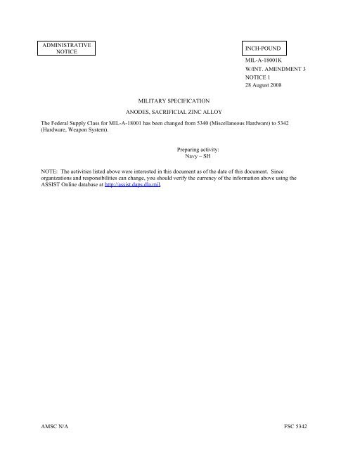
ADMINISTRATIVE<br />
NOTICE<br />
<strong>MIL</strong>ITARY SPECIFICATION<br />
ANODES, SACRIFICIAL ZINC ALLOY<br />
INCH-POUND<br />
<strong>MIL</strong>-A-<strong>18001K</strong><br />
W/INT. AMENDMENT 3<br />
NOTICE 1<br />
28 August 2008<br />
The Federal Supply Class for <strong>MIL</strong>-A-18001 has been changed from 5340 (Miscellaneous Hardware) to 5342<br />
(Hardware, Weapon System).<br />
Preparing activity:<br />
Navy – SH<br />
NOTE: The activities listed above were interested in this document as of the date of this document. Since<br />
organizations and responsibilities can change, you should verify the currency of the information above using the<br />
ASSIST Online database at http://assist.daps.dla.mil.<br />
AMSC N/A FSC 5342
<strong>MIL</strong>ITARY SPECIFICATION<br />
ANODES, SACRIFICIAL ZINC ALLOY<br />
INCH-POUND<br />
<strong>MIL</strong>-A-<strong>18001K</strong>(NAVY)<br />
w/ INT. AMENDMENT 3<br />
24 October 2007<br />
USED IN LIEU OF<br />
<strong>MIL</strong>-A-<strong>18001K</strong><br />
w/AMENDMENT 2<br />
02 May 2005<br />
This specification is approved for use by all Departments and Agencies of the Department of Defenses.<br />
1. SCOPE<br />
1.1 Scope. This specification covers the requirements for zinc anodes (galvanic protectors) in the form of<br />
plates, slabs, discs and rods for corrosion protection (cathodic protection) of metals and alloys. It also includes<br />
features of anode design and fabrication such as cast-in cores for mounting purposes. The material described by this<br />
specification contains elements for which the Occupational Safety and Health Administration (OSHA) has set<br />
standards for exposure limits. Handling, storage, and application of this material should be in accordance <strong>with</strong> the<br />
most recent Code of Federal Regulations Title 29, Part 1910 and 1915 and any other safety and health regulations<br />
(local or otherwise) which may apply.<br />
1.2 Classification.The anodes are of the following classes and types, as specified (see 6.2).<br />
1.2.1 Class 1 – Cast-in cores<br />
Type ZHS – <strong>Zinc</strong>, hull slab (steel straps) (23 and 42 pound sizes).<br />
Type ZHB – <strong>Zinc</strong>, hull slab (brass straps) (23 pound size).<br />
Type ZHC – <strong>Zinc</strong>, hull slab (core straps) (23 and 42 pound sizes).<br />
Type ZSS – <strong>Zinc</strong>, submarine slab (steel strap) (12 and 24 pound sizes).<br />
Type ZTS – <strong>Zinc</strong>, teardrop shape (steel strap) (5 pound size) in accordance <strong>with</strong> NACA 460.<br />
Type ZEP – <strong>Zinc</strong>, heat exchanger or fair water disc (pipe core or pipe bushing core).<br />
Style A – Square slab (9 pound size).<br />
Style B – Circular slab (various sizes).<br />
Style C – Semi-circular slab (23 pound size).<br />
Type ZBP – <strong>Zinc</strong>, bar (pipe core) (8 pound size).<br />
Type ZDM – <strong>Zinc</strong>, segmented disc (machine formed interlocking core).<br />
Type ZMP – <strong>Zinc</strong>, mooring chain (pipe core or pipe bushing core) (various sizes).<br />
Comments, suggestions, or questions on this document should be addressed to: Commander, Naval Sea Systems<br />
Command, ATTN: SEA 05M3, 1333 Isaac Hull Avenue, SE, Stop 5160, Washington Navy Yard DC 20376-5160 or<br />
emailed to CommandStandards@navy.mil, <strong>with</strong> the subject line “Document Comment”. Since contact information<br />
can change, you may want to verify the currency of this address information using the ASSIST Online database at<br />
http://assist.daps.dla.mil.<br />
AMSC N/A FSC 5340
Class 2 – Plain, no cores<br />
<strong>MIL</strong>-A-<strong>18001K</strong>(NAVY)<br />
w/ INT. AMENDMENT 3<br />
Type ZRN – <strong>Zinc</strong>, rod, no core, extruded, drawn or rolled.<br />
Type ZPN – <strong>Zinc</strong>, plate, no core, rolled.<br />
1.3 Key to symbols. The letter designation of types of anodes have the following meaning:<br />
First letter Z – (zinc) designates anode metal.<br />
Second letter H – (hull slab) Designates shape or general use<br />
S – (submarine slab)<br />
T – (teardrop shape)<br />
E – (heat exchanger slab)<br />
R – (rod, cylindrical)<br />
P – (plate)<br />
B – (bar, square)<br />
D – (disc, segmented)<br />
M – (mooring chain)<br />
Third letter B - (brass straps) Designates core<br />
2. APPLICABLE DOCUMENTS<br />
2.1 Government documents.<br />
S – (steel strap)<br />
C – (core, strap)<br />
P – (pipe core)<br />
M – (machine formed<br />
interlocking core)<br />
N – (no core)<br />
2.1.1 Specification, standards, and handbooks. The following specifications, standards, and handbooks form a<br />
part of this document to the extent specified herein. Unless otherwise specified, the issues of these documents are<br />
those cited in the solicitation or contract.<br />
FEDERAL SPECIFICATIONS<br />
QQ-B-639 - Brass, Naval: Flat Products (Plate, Bar, Sheet, and Strip)<br />
FEDERAL STANDARDS<br />
FED-STD-H28 - Screw-Thread Standards for Federal Services<br />
FED-STD-H28/7 - Screw-Thread Standards for Federal Services Section 7 Pipe Threads,<br />
General Purpose<br />
2
<strong>MIL</strong>-A-<strong>18001K</strong>(NAVY)<br />
w/ INT. AMENDMENT 3<br />
(Copies of these documents are available online at http://assist.daps.dla.mil/quicksearch/ or<br />
http://assist.daps.dla.mil or from the Standardization Document Order Desk, 700 Robbins Avenue, Building 4D,<br />
Philadelphia, PA 19111-5094.)<br />
2.2 Non-Government publications. The following specifications, standards, and handbooks form a part of this<br />
document to the extent specified herein. Unless otherwise specified, the issues of these documents are those cited in<br />
the solicitation or contract.<br />
ASTM INTERNATIONAL<br />
A36 - Standard Specification for Carbon Structural Steel<br />
A53 - Standard Specification for Pipe, Steel, Black and Hot-Dipped, <strong>Zinc</strong>-Coated<br />
Welded and Seamless. (DOD adopted)<br />
A513 - Standard Specification for Electric-Resistance-Welded Carbon and <strong>Alloy</strong><br />
Steel Mechanical Tubing<br />
B139 - Standard Specification for Phosphor Bronze Rod, Bar, and Shapes<br />
E290 - Standard Test Method for Bend Testing of Material for Ductility<br />
E536 - Standard Test Methods for Chemical Analysis of <strong>Zinc</strong> and <strong>Zinc</strong> <strong>Alloy</strong>s.<br />
(Copies of these documents are available from ASTM International, 100 Barr Harbor Drive, West<br />
Conshohocken, PA 19428-2959 or online at www.astm.org.)<br />
NATIONAL ADVISORY COMMITTEE FOR AERONAUTICS (NACA)<br />
460 - The Characteristics of 78 Related Airfoil Sections From Tests in the<br />
Variable-Density Wind Tunnel<br />
(Copies of this document is available from NASA/ASRC Aerospace, 7121 Standard Drive, Hanover, MD<br />
21076, Attn: Help Desk or http://naca.larc.nasa.gov/.)<br />
2.3 Order of precedence. In the event of a conflict between the text of this document and the references<br />
cited herein the text of this document takes precedence. Nothing in this document, however, supersedes applicable<br />
laws and regulations unless a specific exemption has been obtained.<br />
3. REQUIREMENTS<br />
3.1 Materials.<br />
3.1.1 <strong>Zinc</strong>. The anodes shall conform to the composition specified in Table I as determined by the methods<br />
specified herein. Total of elemental constituents not specified in Table I shall not exceed 0.10 percent.<br />
TABLE I. Chemical composition, zinc anodes (galvanic protectors).<br />
Lead<br />
(max)<br />
Percent<br />
0.006<br />
Iron<br />
(max)<br />
Percent<br />
0.005<br />
Cadmium<br />
range<br />
Percent<br />
0.025-0.07<br />
3<br />
Copper<br />
(max)<br />
Percent<br />
0.005<br />
Aluminum<br />
range<br />
Percent<br />
0.1-0.5<br />
<strong>Zinc</strong><br />
(min)<br />
Percent<br />
99.314
<strong>MIL</strong>-A-<strong>18001K</strong>(NAVY)<br />
w/ INT. AMENDMENT 3<br />
3.1.2 Steel Straps and pipe cores. Types ZHS, ZHC, ZSS and ZTS anodes shall have steel strap cores<br />
confirming to ASTM A36. Types ZEP and ZBP anodes shall have steel strap cores conforming to ASTM A53.<br />
Type ZMP anodes shall have steel pipe cores conforming to ASTM A53 and A513. The steel shall be coated <strong>with</strong><br />
zinc to a minimum thickness of 0.0005 inch. Hot dip or electrodeposition methods may be used. Either coating<br />
shall be adherent and free from flaking. The coating shall adhere tenaciously to the surface of the base metal. When<br />
the coating is cut or pried into, such as <strong>with</strong> a stout knife applied <strong>with</strong> considerable pressure in a manner tending to<br />
remove a portion of the coating, it shall only be possible to remove small particles of the coating by paring or<br />
whittling, and it shall not be possible to peel any portion of the coating so as to expose the steel. Lack of adhesion of<br />
the zinc coating at bends or absence of zinc coating at cut edges shall not be cause for rejection of fabricated anodes.<br />
3.1.3 Brass straps. Type ZHB zinc anodes shall have brass strap cores conforming to alloy 482 of QQ-B-639<br />
or phosphor bronze straps conforming to composition A of ASTM B139. The brass or bronze straps shall be coated<br />
<strong>with</strong> zinc to a minimum thickness of 0.0005 inch. Lack of adhesion of the zinc coating at bend or absence of zinc<br />
coating at cut edges will not be cause for rejection or fabricated anodes. Cracks in the base metal shall be cause for<br />
rejection. The maximum copper content in the zinc, as specified in Table I, may be increased to 0.020 percent for<br />
type ZHB anodes.<br />
3.1.4 Steel machine formed interlocking cores. Type ZDM zinc anodes shall have machine formed<br />
interlocking cores conforming to commercial grade mild or leaded steel. The cores shall be flash coated <strong>with</strong> zinc,<br />
tin or aluminum prior to assembly <strong>with</strong>in the zinc anodes.<br />
3.1.5 Recovered materials steel components only. Unless otherwise specified herein, all equipment, material<br />
and articles incorporated in the products covered by this specification shall be new and shall be fabricated using<br />
materials produced from recovered materials to the maximum extent practicable <strong>with</strong>out jeopardizing the intended<br />
use. The term “recovered materials” means materials which have been collected or recovered from sold waste and<br />
reprocessed to become a source of raw materials, as opposed to virgin raw materials. None of the above shall be<br />
interpreted to mean that the use of used or rebuilt products is allowed under this specification unless otherwise<br />
specifically specified.<br />
3.1.6 OSHA standards. The material described by this specification contains elements for which the<br />
Occupational Safety and Health Administration (OSHA) has set standards for exposure limits. Handling, storage,<br />
and application of this material should be in accordance <strong>with</strong> the most recent Code of Federal Regulations Title 29,<br />
Part 1910 and 1915 and any other safety and health regulations (local or otherwise) which may apply.<br />
4
3.2 Manufacture.<br />
<strong>MIL</strong>-A-<strong>18001K</strong>(NAVY)<br />
w/ INT. AMENDMENT 3<br />
3.2.1 Types ZHS, ZHB, and ZHC, hull slab anodes (see Figure 4 through 7), types ZSS submarine slab anode<br />
and ZTS teardrop anodes (see Figures 8, 9a, and 9b). Type ZHS, ZHB, ZHC, Z22, and ZTS anodes shall be<br />
manufactured by any casting process suitable to the contracting agency provided the anodes meet the other<br />
requirements covered by this specification. Open or closed molds may be used. Cores and straps shall be positioned<br />
so that they are embedded 1/4 inch minus 1/16 inch or plus 1/8 inch as shown on Figures 4 through 9 which may be<br />
measured from either surface of anode as applicable, except Figure 9(b) which shall be embedded 3/8 inch minus<br />
1/16 inch or plus 1/8 inch. A metallurgical bond shall be obtained between the zinc and the strap when tested as<br />
specified in 4.4.2 or 4.4.2.1. Type ZHC anodes designated as shown on Figures 6A and 7A are intended for use<br />
<strong>with</strong> rubber washers for submarine application. Countersink for rubber washer may be cast or machined. Anode<br />
shall be manufactured so that countersink is centered on core hole. Type ZSS anodes designated as shown on Figure<br />
9 may be mounted by welding or by fasteners. Those intended to be attached by fasteners shall indicated the<br />
requirements for mounting holes in the strap. The mounting hole shall be counterbored on the structure side of the<br />
strap.<br />
3.2.2 Type ZEP heat exchanger slab anode and type ZMP mooring chain anode (see Figures 10 and 13). Type<br />
ZEP and ZMP anodes may be manufactured by any method suitable to the contracting agency provided the anodes<br />
meet the other requirements of this specification. The pipe core inserts shall conform to 3.1.2. A sound<br />
metallurgical bond shall be obtained between the core and anode material for at least 30 percent of the total surface<br />
of the core in contact <strong>with</strong> the anode as specified in 4.4.2 or 4.4.2.1. The position of the pipe core insert shall not<br />
vary more than plus or minus 1/8 inch from center as shown on Figures 10 and 13.<br />
3.2.3 Type ZBP, zinc bar anode (see Figure 11). Type ZBP anodes may be manufactured by any method<br />
suitable to the contracting agency provided the anodes meet the other requirements of this specification. The<br />
position of the pipe core insert specified in 3.1.2 shall not vary more than plus or minus ¼ inch from the center as<br />
shown on Figure 11. The metallurgical bonding requirements between anode and core specified in 4.4.2 shall apply.<br />
3.2.4 Types ZPN and ZRN anodes (no core) (see Figure 12). Type ZPN and ZRN anodes (no core) shall be<br />
manufactured by any process suitable to the contracting agency provided the anodes pass the tests demonstrating<br />
mechanical properties (see 3.6) and other requirements covered by this specification.<br />
3.2.5 Type ZDM, zinc segmented disc, machine formed interlocking core anode (see Figure 1). Type ZDM<br />
anode may be manufactured by any method suitable to the contracting agency provided the anodes meet the other<br />
requirements of this specification. Metallic bonding or an interference fit of the core into the anode shall be required<br />
so that an axial force applied from the stud end to remove the core insert is a minimum of 750 pounds.<br />
3.2.5.1 Core insert. The machine formed core insert specified in 3.1.4 shall be manufactured in accordance<br />
<strong>with</strong> details and tolerances shown in piece 2 of figure 1 FED-STD-H28 and FED-STD-H28/7. (This core insert has<br />
been designed for mass production by modern machine methods. The insert consists of an integral piece having a<br />
threaded male stud at one end and a tapped hole at the other end. Provision has been made to achieve self-locking<br />
characteristics to interlocking threaded assemblies of multiple segmented anode discs by interference fit of bottom<br />
male threads into a taper tapped hole). These anodes shall screw together very snugly by hand tightening or by<br />
using simple hand tools such as pliers or pipe wrenches.<br />
3.3 Dimensions.<br />
3.3.1 Types ZHS, ZHB, ZHC, ZTS, ZSS, ZEP, ZBP, ZDM, ZRN, and ZMP. The specified anodes shall<br />
conform to the dimensions shown on Figures 1 to 13, inclusive. Dimensions are in inches unless otherwise<br />
indicated.<br />
3.3.2 Types ZPN anodes. Type ZPN anode shall be 48 inches in length by 24 inches in width.<br />
3.3.2.1 Thickness. Thickness of type ZPN anode shall be either ½ or 1 inch, as specified (see 6.2).<br />
5
<strong>MIL</strong>-A-<strong>18001K</strong>(NAVY)<br />
w/ INT. AMENDMENT 3<br />
3.3.3 Weight. ZSS-24, ZSS-12, ZHC-42, ZHC-23,ZHS-42, and ZHS-23 shall have the following minimum<br />
weight requirements: ZSS-24 (21.5), ZSS-12 (11.0), ZHC-42 (39), ZHC-23 (20.4), ZHS-42 (41) and ZHS-23 (21.5)<br />
pounds, as indicated in parenthesis. The total weight of the specified type of anode received divided by the total<br />
number of anodes of that type, shall be equal to or greater than the minimum (that is, 21.5, 11.0, 39, or 41) weight of<br />
anode type specified. If the weight is less than the minimum weight for the type of anode specified, it shall be cause<br />
for rejection of the entire lot.<br />
3.4 Permissible variation in dimensions. Dimensions shall be in accordance <strong>with</strong> Figures 1 through 13.<br />
3.4.1 Length and width of types ZHS, ZHB, ZHC, ZTS, ZPN, ZSS and ZBP anodes. The width and length of<br />
the zinc alloy on types ZHC, ZHB, ZHC, ZTS, ZPN, ZSS and ZBP anodes shall not vary more than plus or minus<br />
1/8 inch, measured at widest surface of the tapered (for mold release) anode.<br />
3.4.2 Length of type ZRN anodes. A variation of plus or minus 1 inch will be permitted based on nominal<br />
lengths of 3 and 6 feet.<br />
3.4.3 Diameter of types ZEP, ADM, and ZRN anodes. The diameter or width, whichever is the larger, of type<br />
ZEP anode shall not vary from the specified dimension by more than plus or minus 1/8 inch. The diameter of the<br />
type ZDM anode shall not vary more than plus 0.025 or minus 0.005 inches from the specified diameter. The<br />
diameter of the ZRN anode shall not vary more than plus or minus 1/32 inch from the specified diameter.<br />
3.4.4 Thickness. The thickness of types of ZHS, ZHB, ZHC, ZTS, ZPN, ZSS, ZEP and ZBP zinc anodes shall<br />
not vary more than plus or minus 1/8 inch. Except for ZEP anodes, thickness measurements shall be taken at<br />
random 1 inch from any edge of the anode by means of a suitable caliper, avoiding any surface irregularities which<br />
would interfere <strong>with</strong> a representative measurement. ZEP thickness measurements shall be taken at random, a<br />
distance from the edge of approximately one-half the radius of the anode. The thickness of type ZDM anode shall<br />
not vary more than plus or minus 1/64 inch.<br />
3.4.5 Eccentricity of core in type ZDM anode. The cores of type ZDM anode shall be positioned axially and<br />
concentrically in the zinc disc. Eccentricity greater than 0.005 inch shall not be permitted.<br />
3.4.6 Stud hole elongation for type ZSS anodes. If specified (see 6.2), ZSS straps may be provided and<br />
modified as shown on Figure 9A.<br />
3.5 Marking of anodes.<br />
3.5.1 Prohibition of painting. The zinc anodes, types ZHS, ZHB, ZHC, ZSS, ZBP and ZMP shall have the<br />
words, “DO NOT PAINT” die-stamped or cast on the exposed face of the anodes (see Figures 4, 5, 7, 9, 11 and 13).<br />
No marking shall be required for types ZEP, ZPN, ZDM, ZTS and ZRN zinc anodes. For type ZMP, the nominal<br />
anode size shall be marked as specified on Figure 13.<br />
3.5.1.1 Type ZHB anode markings. One end of each cast-strap of each type ZHB anode shall be painted red so<br />
that the installing activity can distinguish it from type ZHS anodes. One coat of red paint shall be applied between<br />
the joggled bevel of the strap and zinc anode. The coating shall be approximately 1/2 inch wide and shall extend<br />
across one side of each strap so as to be readily visible when the anode is installed. The foot of the strap shall not be<br />
painted.<br />
3.5.2 Heat identification. Each anode shall be cast or die-stamped <strong>with</strong> the following: manufactures symbol,<br />
unique non-recurring heat number, and capital letter corresponding, to the revision letter of the military specification<br />
to which the anode conforms. (For this specification issue, the letter “K” should be used.)<br />
3.6 Mechanical properties.<br />
3.6.1 Fracture or cracking. When tested in accordance <strong>with</strong> 4.4.4.1, type ZRN rods and ZPN plates shall not<br />
fracture or show signs of cracking.<br />
3.6.2 Torsional shear strength. When tested in accordance <strong>with</strong> 4.4.4.2, type ZRN anodes shall have a<br />
minimum Torsional shear strength of 12,000 pounds per square inch (lb/in 2 ).<br />
3.7 Workmanship.<br />
6
<strong>MIL</strong>-A-<strong>18001K</strong>(NAVY)<br />
w/ INT. AMENDMENT 3<br />
3.7.1 <strong>Zinc</strong>. The zinc anodes shall be free of flash burrs, cracks, blow holes, pipes and surface slag consistent<br />
<strong>with</strong> good commercial practice. Anode surfaces will be visually inspected at 10X magnification. No cracks <strong>with</strong> a<br />
surface length of greater than 1/8 inch shall be allowed. The cast anodes shall be free of shrinkage cavities<br />
exceeding 1/4 inch in depth, except that anodes 2 inches thick or more shall be free of shrinkage cavities exceeding<br />
3/8 inch in depth, when measured from a straight edge placed diagonally across the opposite edges of the anode,<br />
except for type ZPN anodes, the shrinkage cavities shall be measured over a 12- by 12-inch area. In addition to the<br />
above allowable shrinkage cavities, surface irregularities of the anode exceeding 1/8 inch in depth shall not be<br />
permitted on one face of slab or disc type anodes unless at least 1/8 inch of sound metal covers the entire strap of<br />
core area. Types ZDM and ZRN anodes shall be smooth on their curved surfaces.<br />
3.7.2 Metal cores. Metal cores extensions from the anodes shall be smooth and free of sharp burrs. The cast-in<br />
cores shall have metallurgical bonds specified herein free of air pockets and inclusions consistent <strong>with</strong> good<br />
commercial practice.<br />
4. QUALITY ASSURANCE PROVISIONS<br />
4.1 Responsibility for inspection. Unless otherwise specified in the contract or purchase order, the contractor is<br />
responsible for the performance of all inspection requirements (examinations and tests) as specified herein. Except<br />
as otherwise specified in the contract or purchase order, the contractor may use his own or any other facilities<br />
suitable for the performance for the inspection requirements specified herein, unless disapproved by the<br />
Government. The Government reserves the right to perform any of the inspections set forth in the specification<br />
where such inspections are deemed necessary to ensure supplies and services conform to prescribed requirements.<br />
4.1.1 Responsibility for compliance. All items shall meet all requirements of sections 3 and 5. The inspection<br />
set forth in this specification shall become a part of the contractor’s overall inspection system or quality program.<br />
The absence of any inspection requirements in the specification shall not relieve the contractor of the responsibility<br />
of ensuring that all products or supplies submitted to the Government for acceptance comply <strong>with</strong> all requirements<br />
of the contract. Sampling inspection, as part of the manufacturing operations, is an acceptable practice to ascertain<br />
conformance to requirements, however, this does not authorize submission of known defective material, either<br />
indicated or actual, nor does it commit the Government to accept defective material.<br />
4.2 Quality conformance inspection.<br />
4.2.1 Lot. For the purpose of sampling, a lot shall consist of all zinc anodes of the same class and type, poured<br />
or cast from one homogeneous heat or melt of a single charge or raw materials. The addition of any material to the<br />
heat or melt at any time constitutes a new lot.<br />
4.2.2 Sampling for visual and dimensional examination. As a minimum, the contractor shall select a sample<br />
quantity of anodes from each lot in accordance <strong>with</strong> table II and inspect them in accordance <strong>with</strong> 4.3. If one or more<br />
defects are found in any sample, the entire lot shall be rejected. The contractor has the option of screening 100<br />
percent of the rejected lot for the defective characteristic(s) or providing a new lot which shall be inspected in<br />
accordance <strong>with</strong> the sampling plan provided herein.<br />
7
<strong>MIL</strong>-A-<strong>18001K</strong>(NAVY)<br />
w/ INT. AMENDMENT 3<br />
TABLE II. Sampling for visual and dimensional examination.<br />
Lot size Sample size Accept Reject1<br />
2-25 3 0 1<br />
26-50 5 0 1<br />
51-90 6 0 1<br />
91-150 7 0 1<br />
151-280 10 0 1<br />
281-500 11 0 1<br />
501-1200 15 0 1<br />
1201-3200 18 0 1<br />
3201-10,000 22 0 1<br />
10,000-over 29 0 1<br />
4.2.3 Sampling for core bond tests. From each lot specified in 4.2.1, two anodes shall be selected at random of<br />
types ZHS, ZHB, ZHC, ZSS, ZTS, ZEP, ZMP, and ZBP and five anode discs of type ZDM for the test specified in<br />
4.4.2.<br />
4.2.4 Sampling for chemical analysis. <strong>Anodes</strong> shall be taken from each homogenous lot to verify compliance<br />
<strong>with</strong> the chemical requirements of 3.1.1 and Table I. As a minimum, the first, middle, and last poured anode shall<br />
be tested to verify compliance <strong>with</strong> the chemical requirements of 3.1.1 and Table I. Failure to meet the requirements<br />
of 3.1.1 shall be cause for the rejection of the anode and the lot from which the failed anode originated. The drilling<br />
for chemical analysis shall be made <strong>with</strong> a special nonferrous drill bit. See 4.2.4.6, 6.5.1 and 6.5.2 for sample<br />
preparation and drilling procedure. From each of the required anodes, one 2-ounce sample shall be taken by drilling<br />
or machining the material at the locations specified in 4.2.4.1 to 4.2.4.6, inclusive. The drilling or machining shall<br />
be done by the contractor. The drill or tool bit shall not penetrate into the core material of the cored type anodes.<br />
The drilled or machined anodes may be included in the delivery of the material, except type ZDM which shall be<br />
discarded. Chemical test records shall be retained to verify test results, for a minimum of 5 years.<br />
4.2.4.1 Drilling locations. Type ZHS, ZHB and ZPN anodes shall be drilled or machined at locations about 2<br />
to 5 inches from the short edge as appropriate to keep away from the encased core.<br />
4.2.4.2 Drilling precautions. Type ZSS, ZHC and ZTS anodes shall be drilled or machined at points not greater<br />
than ½ inch from the long edge.<br />
4.2.4.3 Drilling points for types ZEP, ZMP, and ZBP. Type ZEP, ZMP, and ZBP anodes shall be drilled at<br />
points midway between outer edge of the core and the edge of the anode.<br />
4.2.4.4 Types ZRN and ZDM samples. Type ZRN anodes shall have two 1-pound minimum sections cut from<br />
ends of a nominal length. Type ZDM anodes shall have a sufficient number of discs machined or drilled to make<br />
two 4-ounces quantities. The anode shall be sampled as specified in 4.2.4.5 and 4.2.4.6.<br />
4.2.4.5 Type ZDM. Type ZDM anodes shall be machined or drilled at the outer surface to a depth not<br />
exceeding ¼ inch.<br />
1 Rejected lots may be screened by the contractor and twice the sample size resubmitted for acceptance inspection<br />
and tested <strong>with</strong> same accept/reject criteria. All defective items must be replaced <strong>with</strong> acceptable items prior to lot<br />
acceptance. Resubmitted lots that fail retest shall be rejected.<br />
8
<strong>MIL</strong>-A-<strong>18001K</strong>(NAVY)<br />
w/ INT. AMENDMENT 3<br />
4.2.4.6 Surface chips. One 2-ounce sample for each anode specified in 4.2.4 shall be taken at the surface in<br />
contact <strong>with</strong> mold wall by drilling or machining to a maximum depth of 1/4 inch. The sample for types ZPN or<br />
ZRN shall be taken by drilling completely through both larger surfaces or through the diameter of the anode as<br />
applicable. The samples shall be collected in individual clean containers, and properly labeled as to lot, melt, and<br />
sample numbers. Sample ships may be taken from anodes which have passed the applicable bond test. Samples<br />
shall be clean, free from dirt, oil, grit and foreign matter. The samples shall be sent to a laboratory satisfactory to<br />
the contracting agency. A method for sampling anodes for chemical analysis is specified in 6.5.<br />
4.2.5 Sampling for physical testing. At least five type ZRN and five type ZPN anodes shall be selected at<br />
random from a lot. Type ZRN anodes shall conform to the tests specified in 4.4.4. Type ZPN anodes shall conform<br />
to the test specified in 4.4.4.1.<br />
4.2.5.1 Physical test sample dimensions for ZPN type anodes. ZPN test samples shall be cut from the plate<br />
anodes and shall be of the following dimensions:<br />
Width: Twice the thickness of the anode.<br />
Length: 12 inches (or to suit test apparatus).<br />
4.3 Visual and dimensional examination. Each anode selected in accordance <strong>with</strong> 4.2.2 shall be examined for<br />
conformance to requirements of 3.3 through 3.7. If any number of anodes do not conform to 3.3 through 3.7 it shall<br />
be cause for rejection of the entire lot.<br />
4.4 Tests. The following tests shall be performed.<br />
4.4.1 Weight test. The entire lot of each type anode shall meet the weight requirements as specified in 3.3.3.<br />
4.4.2 Core bonding test. One of the following core bonding test shall be performed on each anode selected in<br />
accordance <strong>with</strong> 4.2.3.<br />
4.4.2.1 Core bonding tests (types ZHS, ZHB, ZHC, ZSS, ZTS, ZMP, ZEP and ZBP). Each anode selected to<br />
represent the lot shall be cut along the axis of each strap or core, and the cut surface shall be ground reasonably<br />
smooth. These surfaces shall be polished <strong>with</strong> a 240-mesh emery abrasive until the zinc-strap interface is distinctly<br />
visible. At least 30 percent of this interface shall show no separation when examined at approximately 10X<br />
magnification. <strong>Zinc</strong> anodes may have a bead or buttress projecting from the anode edge along the strap not<br />
exceeding ¼ inch. Less bond between core and zinc than specified herein shall be cause for rejection of the lot.<br />
4.4.2.2 Alternate core bonding test (types ZHS, ZHB, ZHC, ZSS, ZTS, ZMP, ZEP and ZBP) Using any<br />
suitable method, the cores shall be torn from each anode selected to represent the lot. The use of a sledge hammer to<br />
break the zinc away from the cores has been found to be satisfactory. The area showing bond shall be established by<br />
visual inspection of the portion of the cores which were contained <strong>with</strong>in the anode. Metallurgical bond between the<br />
zinc and the core shall be at least 30 percent of the total surface area of each core in contact <strong>with</strong> the zinc of the<br />
anode. For the purpose of determining the surface area of the encased core in the anode, marks shall be scribed on<br />
the strap around the periphery of each anode at locations where the straps protrude from the anode. The total area of<br />
the strap shall be computed between the scribe marks. The surfaces shall have a smooth grey matte finish where<br />
bonding has been adequate and either a shiny metallic or rough, dark or discolored finish where bonding has been<br />
inadequate. Examine both core and zinc mating surfaces. Less bond between core and zinc than that specified<br />
herein shall be cause for rejection of the entire lot.<br />
4.4.2.3 Type ZDM anode. A minimum steady pressure of 750 pounds from a hand operated pen press applied<br />
axially shall be required to remove the core from the anode.<br />
4.4.2.4 Sample anodes. Sample anodes shall be discarded and not included in the delivery of material after the<br />
core bond tests are performed. The remaining lengths of ZRN and ZPN anodes may be included in the delivery of<br />
material after the physical tests of 4.4.4. Sampling for chemical analysis specified in 4.2.4 shall be made prior to<br />
discarding the anodes specified in 4.4.2.1 through 4.4.2.3.<br />
9
<strong>MIL</strong>-A-<strong>18001K</strong>(NAVY)<br />
w/ INT. AMENDMENT 3<br />
4.4.3 Chemical analysis. The chips selected in accordance <strong>with</strong> 4.2.4 shall be analyzed to determine<br />
conformance <strong>with</strong> 3.1.1. A strong magnet shall be used to remove any iron contamination picked up during the<br />
preparation of the chips. The chips shall be washed in an iron-free degreasing solvent prior to analysis. If any<br />
sample does not conform to the chemical composition specified in Table I, it shall be cause for rejection of the lot<br />
represented by the sample.<br />
4.4.3.1 Determination of aluminum, cadmium, copper, iron and lead. The aluminum, cadmium, copper, iron<br />
and lead content of zinc shall be determined in accordance <strong>with</strong> the appropriate methods in ASTM E536 using the<br />
atomic absorption, inductively coupled plasma, or directly coupled plasma spectrophotometers.<br />
4.4.3.2 Spectrochemical analysis. Spectrochemical analysis shall be in accordance <strong>with</strong> any standard method<br />
approved by a standard issue body such as the American National Standards Institute or ASTM E536 and accepted<br />
by the Government.<br />
4.4.4 Physical tests.<br />
4.4.4.1 Bend test. Type ZRN anodes, selected in accordance <strong>with</strong> 4.2.5, shall be bent 45 degrees around a<br />
mandrel of three times the diameter of the ZRN type anode. Type ZPN anodes, selected in accordance <strong>with</strong> 4.2.5,<br />
shall be bent 45 degrees around a mandrel that has the diameter of three times the thickness of ZPN anodes. The<br />
anodes shall be bent in accordance <strong>with</strong> procedures specified in ASTM E290. After bending, the convex surface of<br />
the specimens shall be inspected for cracking by visual examination. Any evidence of cracking shall represent<br />
failure of the test and shall be cause for rejection of the entire lot.<br />
4.4.4.2 Torsional shear test. Type ZRN anodes, selected in accordance <strong>with</strong> 4.2.5, shall be subjected to<br />
torsional shear at a rate of 10 to 12 revolutions per hour using a Tinius-Olson torsional shear apparatus, or equal.<br />
Failure of the anode to <strong>with</strong>stand a torsional shear of 12,000 lb/in 2 shall be cause for rejection of the lot.<br />
4.5 Inspection of packaging. Sample packages and packs, and the inspection of the preservation, packing and<br />
marking for shipment, stowage and storage shall be in accordance <strong>with</strong> the requirements of section 5 and the<br />
documents specified therein.<br />
5. PACKAGING<br />
5.1 Packaging. For acquisition purposes, the packaging requirements shall be as specified in the contract or<br />
order. When packaging of material is to be performed by DoD or in-house contractor personnel, these personnel<br />
need to contact the responsible packaging activity to ascertain packaging requirements. Packaging requirements are<br />
maintained by the Inventory Control Point’s packaging activities <strong>with</strong>in the Military Service or Defense Agency, or<br />
<strong>with</strong>in the military service’s system commands. Packaging data retrieval is available from the managing Military<br />
Department’s or Defense Agency’s automated packaging files, CD-ROM products, or by contacting the responsible<br />
packaging activity.<br />
6. NOTES<br />
(This section contains information of a general or explanatory nature that may be helpful, but is not mandatory.)<br />
6.1 Intended use.The anodes are primarily intended for use in corrosion prevention in seawater of surface ship<br />
and submarine hulls, steel and aluminum equipment and structures, sea chests, sonar domes, mooring chains, and the<br />
seawater side of condensers and other heat exchangers. The anodes may also be used for corrosion prevention of<br />
pipe lines and other installations underground. The use of a particular anode is determined by the nature and<br />
geometry of the structure to be protected. Refer to applicable installation instructions for types, amounts, locations,<br />
and mounting of anodes.<br />
6.2 Acquisition requirements. Acquisition documents must specify the following:<br />
(a) Title, number, and date of this specification.<br />
(b) Class and type (see 1.2).<br />
(c) As required, the specific issue of individual documents referenced (see 2.1.1 and 2.2).<br />
10
<strong>MIL</strong>-A-<strong>18001K</strong>(NAVY)<br />
w/ INT. AMENDMENT 3<br />
(d) Style of type ZEP, diameter of type ZEP, style B; size of type ZMP (see Figure 13); diameter of type ZDM<br />
anode (see Figure 1); pipe or bolt diameter of type ZRN required (see Figure 12); length, width, and thickness of<br />
types ZHS (see Figures 4 and 5); ZHC, ship or submarine usage <strong>with</strong> neoprene washers (see Figures 6, 6A, 7, and<br />
7A).<br />
(e) Thickness of type ZPN anode, whether 1/2 or 1 inch (see 3.3.2.1).<br />
(f) Elongation of type ZSS anode straps (see 3.4.6).<br />
(g) Total number of anodes required (see 6.3).<br />
11
<strong>MIL</strong>-A-<strong>18001K</strong>(NAVY)<br />
w/ INT. AMENDMENT 3<br />
TABLE IV. National stock numbers.<br />
Anode type Weight-size National Stock Number<br />
ZHS-23 23 lbs 9Z-5342 00-277-7559<br />
ZHS-42 42 lbs 5342 00-134-8131<br />
ZHB-23 23 lbs 5342 00-662-9827<br />
ZHC-23 23 lbs 5342 00-813-6058<br />
ZHC-42 42 lbs 5342 00-486-0957<br />
ZSS-12 12 lbs 5342 00-290-8243<br />
ZSS-12 (Elongated Strap End) 12 lbs 5342 01-356-6382<br />
ZSS-24 24 lbs 5342 01-357-4579<br />
ZSS-24 (Elongated Strap End) 24 lbs 5342 01-356-6383<br />
ZTS-5 5 lbs 5342 01-294-2332<br />
ZEP-A (square) 9 lbs 5342 00-543-3032<br />
ZEP-B (circular) 24 lbs 5342 00-702-1664<br />
" 16 lbs 5342 00-702-1372<br />
" 7.2 lbs 5342 00-702-1371<br />
" 4.9 lbs 5342 00-527-2366<br />
" 3.2 lbs 5342 00-582-2011<br />
" 1.8 lbs 5342 00-582-2012<br />
" 0.8 lbs 5342 00-527-2368<br />
ZEP-C (semi-circular) 23 lbs 5342 00-702-1665<br />
ZBP 8 lbs 5342 00-526-3679<br />
ZDM 1.050 in dia 5342 00-682-2174<br />
" 0.825 in dia 5342 00-725-3999<br />
" 0.625 in dia 5342 00-725-3998<br />
" 0.500 in dia 5342 00-725-3997<br />
ZMP 4 in dia 5342 01-357-4580<br />
" 3.5 in dia 5342 01-356-6384<br />
" 3.0 in dia 5342 01-356-8260<br />
" 2.75 in dia 5342 01-356-6385<br />
" 2.5 in dia 5342 01-356-6386<br />
" 2.25 in dia 5342 01-356-6387<br />
" 2 in dia 5342 01-356-6252<br />
" 1.75 in dia 5342 01-356-6253<br />
" 1.25 in dia 5342 01-361-2565<br />
ZRN 1.315 in dia 5342 00-813-6057 (cancelled)<br />
" 1.050 in dia 5342 00-813-6056<br />
" (6.5 in length) 0.840 in dia 5342 00-576-1749<br />
" (3 ft length) 0.840 in dia 5342 00-664-0531<br />
" (6 ft length) 0.840 in dia 5342 00-796-4354<br />
" (6 ft length) 0.840 in dia 5342 00-813-6055<br />
" 0.675 in dia 5342 00-813-6054<br />
" 0.540 in dia 5342 01-356-6381<br />
" 0.405 in dia 5342 00-813-6053<br />
ZPN 24 * 48 * 0.5 in<br />
5342 00-290-3793<br />
(discontinued)<br />
" 24 * 48 * 1 in 5342 01-358-4414<br />
12
<strong>MIL</strong>-A-<strong>18001K</strong>(NAVY)<br />
w/ INT. AMENDMENT 3<br />
6.3 Ordering by quantity. The order for anodes should specify the exact number of anodes required (see 6.2).<br />
Acquisition of anodes by weight is too practical and is not recommended.<br />
6.4 General forms and dimensions. When material is ordered in the form of slabs, bars, discs, or rods, it is to<br />
be understood that these terms refer merely to the general form and dimensions of the material, and do not have any<br />
technical significance as to the methods of manufacture.<br />
6.5 Sampling procedure.<br />
6.5.1 Drilling procedure. The drilling for chemical analysis should be made <strong>with</strong> a special nonferrous drill in a<br />
clean location (used only for that purpose). The drilling bits should be kept clean of dirt, grit, and other foreign<br />
matter; kept properly sharpened; and used only for sampling purposes. After each use, the drilling bit should be<br />
immersed in a degreasing solvent and wiped dry <strong>with</strong> a clean rag. The drilling bits, when not in use, should be<br />
stored in an inhibited lubricating oil. The inhibited lubricating oil should be kept in a covered glass container<br />
provided <strong>with</strong> an air vent. The drilling bits should be wiped dry <strong>with</strong> a clean rag prior to use. Samples should be<br />
taken <strong>with</strong> a dry drill. If automatic power drilling equipment is available, a solid tungsten carbide or Tantung twist<br />
drill bit about 1/2 inch in diameter is suitable. Where a hand-held power drill is used, the samples should be taken<br />
by drilling <strong>with</strong> a solid tungsten carbide or Tantung twist drill bit about 1/4 inch in diameter. A smaller drill bit may<br />
be used where the size of the anode does not permit using the specified diameters. The drills may be used at high<br />
speeds and feeds.<br />
6.5.2 Machining procedure. The chips for chemical analysis should be made <strong>with</strong> a special nonferrous tool in a<br />
place which has been cleaned for that specific purpose. Instructions specified in 6.5.1 apply to the use and care of<br />
this tool.<br />
6.6 Sub-contracted material and parts. The packaging or preparation for delivery of requirements of referenced<br />
documents listed in section 2 do not apply when material and parts are acquired by the contractor for incorporation<br />
into the equipment and lose their separate identity when the equipment is shipped.<br />
6.7 Subject term (key word) listing.<br />
Corrosion<br />
Disc<br />
Galvanic<br />
Plate<br />
Rod<br />
Slab<br />
6.8 <strong>Amendment</strong> notations. The margins of this specification are marked <strong>with</strong> vertical lines to indicate<br />
modifications generated by this amendment. This was done as a convenience only and the Government assumes no<br />
liability whatsoever for any inaccuracies in these notations. Bidders and contractors are cautioned to evaluate the<br />
requirements of this document based on the entire content irrespective of the marginal notations.<br />
13
<strong>MIL</strong>-A-<strong>18001K</strong>(NAVY)<br />
w/ INT. AMENDMENT 3<br />
14
<strong>MIL</strong>-A-<strong>18001K</strong>(NAVY)<br />
w/ INT. AMENDMENT 3<br />
15
<strong>MIL</strong>-A-<strong>18001K</strong>(NAVY)<br />
w/ INT. AMENDMENT 3<br />
16
<strong>MIL</strong>-A-<strong>18001K</strong>(NAVY)<br />
w/ INT. AMENDMENT 3<br />
17
<strong>MIL</strong>-A-<strong>18001K</strong>(NAVY)<br />
w/ INT. AMENDMENT 3<br />
18
<strong>MIL</strong>-A-<strong>18001K</strong>(NAVY)<br />
w/ INT. AMENDMENT 3<br />
19
<strong>MIL</strong>-A-<strong>18001K</strong>(NAVY)<br />
w/ INT. AMENDMENT 3<br />
20
<strong>MIL</strong>-A-<strong>18001K</strong>(NAVY)<br />
w/ INT. AMENDMENT 3<br />
21
<strong>MIL</strong>-A-<strong>18001K</strong>(NAVY)<br />
w/ INT. AMENDMENT 3<br />
22
<strong>MIL</strong>-A-<strong>18001K</strong>(NAVY)<br />
w/ INT. AMENDMENT 3<br />
23
<strong>MIL</strong>-A-<strong>18001K</strong>(NAVY)<br />
w/ INT. AMENDMENT 3<br />
24
<strong>MIL</strong>-A-<strong>18001K</strong>(NAVY)<br />
w/ INT. AMENDMENT 3<br />
25
<strong>MIL</strong>-A-<strong>18001K</strong>(NAVY)<br />
w/ INT. AMENDMENT 3<br />
26
<strong>MIL</strong>-A-<strong>18001K</strong>(NAVY)<br />
w/ INT. AMENDMENT 3<br />
27
<strong>MIL</strong>-A-<strong>18001K</strong>(NAVY)<br />
w/ INT. AMENDMENT 3<br />
28
<strong>MIL</strong>-A-<strong>18001K</strong>(NAVY)<br />
w/ INT. AMENDMENT 3<br />
29
<strong>MIL</strong>-A-<strong>18001K</strong>(NAVY)<br />
w/ INT. AMENDMENT 3<br />
Custodians: Preparing Activity:<br />
Navy – SH Navy – SH<br />
(Project 5340-2008-002)<br />
Review Activities:<br />
Navy – OS, YD<br />
NOTE: The activities listed above were interested in this document as of the date of this document. Since<br />
organizations and responsibilities can change, you should verify the currency of the information above using the<br />
ASSIST Online database at http://assist.daps.dla.mil.<br />
30


