PULIZZI ENGINEERING INC. - HM Cragg
PULIZZI ENGINEERING INC. - HM Cragg
PULIZZI ENGINEERING INC. - HM Cragg
Create successful ePaper yourself
Turn your PDF publications into a flip-book with our unique Google optimized e-Paper software.
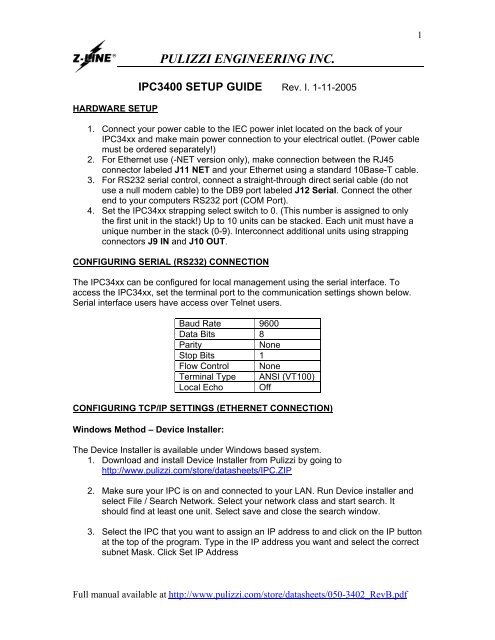
HARDWARE SETUP<br />
<strong>PULIZZI</strong> <strong>ENGINEERING</strong> <strong>INC</strong>.<br />
IPC3400 SETUP GUIDE Rev. I. 1-11-2005<br />
1. Connect your power cable to the IEC power inlet located on the back of your<br />
IPC34xx and make main power connection to your electrical outlet. (Power cable<br />
must be ordered separately!)<br />
2. For Ethernet use (-NET version only), make connection between the RJ45<br />
connector labeled J11 NET and your Ethernet using a standard 10Base-T cable.<br />
3. For RS232 serial control, connect a straight-through direct serial cable (do not<br />
use a null modem cable) to the DB9 port labeled J12 Serial. Connect the other<br />
end to your computers RS232 port (COM Port).<br />
4. Set the IPC34xx strapping select switch to 0. (This number is assigned to only<br />
the first unit in the stack!) Up to 10 units can be stacked. Each unit must have a<br />
unique number in the stack (0-9). Interconnect additional units using strapping<br />
connectors J9 IN and J10 OUT.<br />
CONFIGURING SERIAL (RS232) CONNECTION<br />
The IPC34xx can be configured for local management using the serial interface. To<br />
access the IPC34xx, set the terminal port to the communication settings shown below.<br />
Serial interface users have access over Telnet users.<br />
Baud Rate 9600<br />
Data Bits 8<br />
Parity None<br />
Stop Bits 1<br />
Flow Control None<br />
Terminal Type ANSI (VT100)<br />
Local Echo Off<br />
CONFIGURING TCP/IP SETTINGS (ETHERNET CONNECTION)<br />
Windows Method – Device Installer:<br />
The Device Installer is available under Windows based system.<br />
1. Download and install Device Installer from Pulizzi by going to<br />
http://www.pulizzi.com/store/datasheets/IPC.ZIP<br />
2. Make sure your IPC is on and connected to your LAN. Run Device installer and<br />
select File / Search Network. Select your network class and start search. It<br />
should find at least one unit. Select save and close the search window.<br />
3. Select the IPC that you want to assign an IP address to and click on the IP button<br />
at the top of the program. Type in the IP address you want and select the correct<br />
subnet Mask. Click Set IP Address<br />
Full manual available at http://www.pulizzi.com/store/datasheets/050-3402_RevB.pdf<br />
1
Universal Method – ARP Command:<br />
The ARP method is available under UNIX and Windows based systems. The IPC34xx<br />
network card will set its address from the first directed TCP/IP packet it receives.<br />
1. In a Windows based system, open a MS DOS prompt.<br />
(In a UNIX system, skip step 1 and 2)<br />
2. In order for the ARP command to work in Windows, the ARP table on the PC<br />
must have at least one IP address defined other than its own. If the ARP table is<br />
empty, the command will return an error message. Type ARP -A at the DOS<br />
command prompt to verify that there is at least one entry in the ARP table.<br />
arp –a _<br />
If the local machine has only one entry, ping another IP address on your network<br />
to build a new entry in the ARP table. The IP address you ping must be a number<br />
other than the machine on which you are working.<br />
3. Once there is at least one additional entry in the ARP table, use the following<br />
command to ARP an IP address to the IPC34xx. The first number is the IP<br />
address you wish to assign to your IPC34xx. The second number is the MAC<br />
address of the IPC34xx located on the bottom of your unit:<br />
arp –s xxx.xxx.xxx.xxx 00-20-4a-xx-xx-xx _<br />
(In a UNIX systems enter the arp command as follows:)<br />
arp –s xxx.xxx.xxx.xxx 00:20:4a:xx:xx:xx _<br />
1. Now open a Telnet connection to port 1. The connection will fail quickly (3<br />
seconds), but the IPC34xx will temporarily change its IP address to the one<br />
designated in this step.<br />
Telnet xxx.xxx.xxx.xxx 1 _<br />
2. Open a Telnet connection to port 9999 to set the required parameters. Once the<br />
setup screen opens, you will need to press enter quickly.<br />
Telnet xxx.xxx.xxx.xxx 9999 _<br />
3. After pressing enter you will see a setup menu. Select 0 for Server<br />
Configuration. You will be prompted for the IP address, 3 characters at a time.<br />
Enter the IP address that you would like to assign to the IPC34xx. Enter through<br />
all the other settings.<br />
4. You will return to the main menu. Select 2 for Channel 2 Configuration**. Enter<br />
through the choices, until prompted for the Port No? Enter the desired port<br />
number. Port 23 is the standard Telnet port number, which the unit is default set<br />
to. Enter through all the other settings.<br />
5. You will return to the main menu. Select 9 to Save and Exit. Your IP address<br />
and Port number are now saved in memory.<br />
6. You are now ready to open a Telnet session with the IPC34xx at the specified IP<br />
address and port number.<br />
** Use Channel 1configuration if Channel 2 configuration is not an option on your IPC.<br />
Full manual available at http://www.pulizzi.com/store/datasheets/050-3402_RevB.pdf<br />
2
Serial / Telnet Control<br />
1. Type the unit name and press Enter. (Default is @@@@)<br />
2. The unit will respond with IPC@@@@. You can now execute any of the following list of<br />
commands:<br />
Commands must be entered in all capital letters. is required after each command.<br />
“xx” represents the outlet number “01” to “80”, if no units are stacked, this is “01” to “08”<br />
“n” represents the unit stack number “0” to “9”, if no units are stacked, this number is “0”<br />
Command Description<br />
A1n Turns all outlets ON for any unit “n” in the stack<br />
A0n Turns all outlets OFF for any unit “n” in the stack<br />
Nxx Turn ON any outlet “xx” in the stack individually<br />
Fnn Turn OFF any outlet “xx” in the stack individually<br />
S1n Sequence all outlets in unit “n” ON with preset delays, lowest first<br />
S0n Sequence all outlets in unit “n” OFF with preset delays, highest first<br />
ADn Enter new IPC user name, any 4 characters<br />
ISn<br />
Set the power up/down sequence in unit “n”. Unit will prompt for (P) Preset or (D)<br />
Default. This will determine how the unit powers up after a cycling the main power.<br />
--------------------<br />
P<br />
Preset will allow you to enter the power up delay for each outlet, 000 will reset the<br />
outlet to the OFF position. Enter 001 for a 1 second delay, 002 for a 2 second delay,<br />
etc. up to 999 seconds.<br />
Default will power outlets on in the same state they were before main power was<br />
D<br />
removed.<br />
DXn Displays the outlet status (ON/OFF), watchdog status and remote status for unit “n” in<br />
the stack.<br />
AEn<br />
Auto enable status update for unit “n” in the stack. Unit will prompt you for (Y) yes or<br />
-------------------- (N) no.<br />
Y<br />
Yes- Unit will update status after each change.<br />
N<br />
No- Unit will not update status after each change.<br />
WE0 Watchdog enable for unit “0” in the stack. This will turn on the watchdog feature, which<br />
will reboot unit “0” if no communication is detected with the IPC34xx for the preset time<br />
- see WT0 command.<br />
WT0 Watchdog timeout sets the timeout period for unit “0” in the stack. Unit will prompt you<br />
for the time period. Enter a number “0” to “9”. Each number represents 30 seconds. “0”<br />
is 30 seconds, “1” is 60 seconds, “2” is 90 seconds, and up to “9” is 300 seconds. Unit<br />
will monitor the communications and will reset if no communication is detected within<br />
this set time period.<br />
WD0 Watchdog disable for unit “0” in the stack. This will disable the watchdog feature.<br />
PWn This will turn on the password protection for unit “n” in the stack and will prompt the<br />
user for a 3 character password. Any 3 characters can be used.<br />
PDn This will disable the password protection for unit “n” in the stack.<br />
SR0 System reboot for outlet J1 in unit “0” in the stack. This command will power off and on<br />
outlet J1 with a 5 second reboot period.<br />
LO Log out will end your session with the IPC34xx. This command must be entered twice<br />
to log off from more than one unit in the stack.<br />
? Display the command menu.<br />
CNnx Outlet name entry 8 characters where “n” is the unit number and “x” is the outlet of that<br />
unit **1<br />
DNn Displays the outlet status with outlet names (ON/OFF), watchdog status and remote<br />
status for unit “n” in the stack<br />
**1 Outlet naming commands only work on IPC units manufactured after 9/18/03<br />
Full manual available at http://www.pulizzi.com/store/datasheets/050-3402_RevB.pdf<br />
3
Web Browser Control **2<br />
1. Connect to the IPC in your web browser by going to<br />
http://xxx.xxx.xxx.xxx/webipc.html where xxx.xxx.xxx.xxx is the IP address of<br />
your unit.<br />
2. Type in your user name (default is @@@@) and port number (default is 23). If<br />
you have this unit daisy chained with other units check the stacked button and<br />
click log in. Please note that only one user can be logged onto the IPC at any<br />
given time.<br />
3. Simply click on the buttons to perform the action that you want.<br />
**2. Please note this browser interface has only been tested on Internet Explorer 4.0 or<br />
newer and Netscape 7.0 or newer with the latest version of Java from<br />
http://www.java.com.<br />
In addition to the Z-LINE ® and <strong>PULIZZI</strong> ® registered trademarks, this electrical equipment is<br />
covered by the RACK POWER and AC POWER MASTER Trademarks. All of the abovecited<br />
trademarks are trademarks of Pulizzi Engineering, Inc<br />
SD: F:\M<strong>PULIZZI</strong>\Manuals\IPC3400_QUICK_SETUP_GUIDE_rev_I.doc<br />
CA: F:\DOC\INSERTS\IPC3400_QUICK_SETUP_GUIDE_rev_I.doc<br />
Full manual available at http://www.pulizzi.com/store/datasheets/050-3402_RevB.pdf<br />
4


