POWERTECH™ 13.5 L OEM 6135HF485/HF475 Emis sions Diesel ...
POWERTECH™ 13.5 L OEM 6135HF485/HF475 Emis sions Diesel ...
POWERTECH™ 13.5 L OEM 6135HF485/HF475 Emis sions Diesel ...

You also want an ePaper? Increase the reach of your titles
YUMPU automatically turns print PDFs into web optimized ePapers that Google loves.
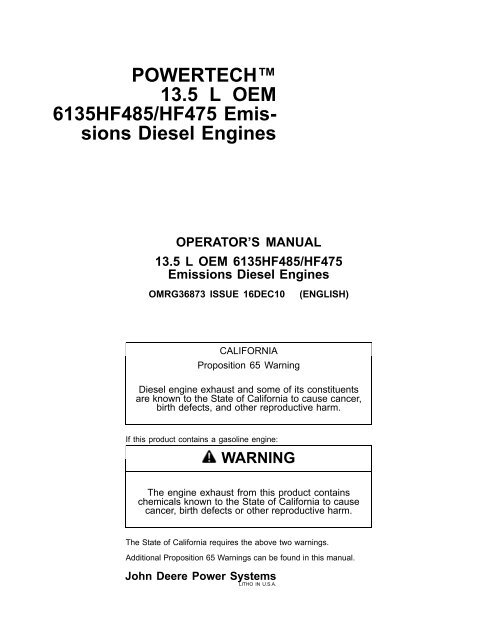
POWERTECH<br />
<strong>13.5</strong> L <strong>OEM</strong><br />
<strong>6135HF485</strong>/<strong>HF475</strong> <strong>Emis</strong><strong>sions</strong><br />
<strong>Diesel</strong> Engines<br />
OPERATOR’S MANUAL<br />
<strong>13.5</strong> L <strong>OEM</strong> <strong>6135HF485</strong>/<strong>HF475</strong><br />
<strong>Emis</strong><strong>sions</strong> <strong>Diesel</strong> Engines<br />
OMRG36873 ISSUE 16DEC10 (ENGLISH)<br />
CALIFORNIA<br />
Proposition 65 Warning<br />
<strong>Diesel</strong> engine exhaust and some of its constituents<br />
are known to the State of California to cause cancer,<br />
birth defects, and other reproductive harm.<br />
If this product contains a gasoline engine:<br />
WARNING<br />
The engine exhaust from this product contains<br />
chemicals known to the State of California to cause<br />
cancer, birth defects or other reproductive harm.<br />
The State of California requires the above two warnings.<br />
Additional Proposition 65 Warnings can be found in this manual.<br />
John Deere Power Systems<br />
LITHO IN U.S.A.
Foreword<br />
READ THIS MANUAL carefully to learn how to operate<br />
and service your engine correctly. Failure to do so could<br />
result in personal injury or equipment damage.<br />
THIS MANUAL SHOULD BE CONSIDERED a permanent<br />
part of your engine and should remain with the engine<br />
when you sell it.<br />
MEASUREMENTS IN THIS MANUAL are given in both<br />
metric and customary U.S. unit equivalents. Use only<br />
correct replacement parts and fasteners. Metric and inch<br />
fasteners may require a specific metric or inch wrench.<br />
RIGHTHAND AND LEFTHAND sides are determined by<br />
standing at the drive or flywheel end (rear) of the engine<br />
and facing toward the front of the engine.<br />
WRITE ENGINE SERIAL NUMBERS and option codes<br />
in the spaces indicated in the Record Keeping section.<br />
Accurately record all the numbers. Your dealer also<br />
needs these numbers when you order parts. File the<br />
identification numbers in a secure place off the engine.<br />
Introduction<br />
SETTING FUEL DELIVERY beyond published factory<br />
specifications or otherwise overpowering will result in loss<br />
of warranty protection for this engine.<br />
CERTAIN ENGINE ACCESSORIES such as radiator,<br />
air cleaner, and instruments are optional equipment on<br />
John Deere <strong>OEM</strong> Engines. These accessories may be<br />
provided by the equipment manufacturer instead of John<br />
Deere. This operator’s manual applies only to the engine<br />
and those options available through the John Deere<br />
distribution network.<br />
NOTE: This operator’s manual covers only engines<br />
provided to <strong>OEM</strong> (Original Equipment<br />
Manufacturers). For engines in Deere machines,<br />
refer to the machine operator’s manual.<br />
This manual covers primarily the PowerTech Plus <strong>13.5</strong><br />
L (<strong>6135HF485</strong>) <strong>OEM</strong> engines. These engines meet<br />
emission standards for EPA Tier 3 and EU Stage III A.<br />
JR74534,00002EA 1916DEC101/1<br />
010311<br />
PN=2
Engine Owner<br />
John Deere Engine Owner:<br />
Don’t wait until you need warranty or other service<br />
to meet your local John Deere Engine Distributor<br />
or Service Dealer. To register your engine for<br />
warranty via the Internet, use the following URL:<br />
http://www.johndeere.com/enginewarranty<br />
Learn who your dealer is and where he is. At your first<br />
convenience, go meet him. He’ll want to get to know you<br />
and to learn what your needs might be.<br />
Aux Utilisateurs De Moteurs John Deere:<br />
N’attendez pas d’être obligé d’avoir recours à votre<br />
concessionnaire John Deere ou au point de service le plus<br />
proche pour vous adresser à lui. Pour enregistrer votre<br />
moteur pour la garantie via Internet, utilisez l’adresse<br />
suivante: http://www.johndeere.com/enginewarranty<br />
Renseignezvous dès que possible pour l’identifier et le<br />
localiser. A la première occasion, prenez contact avec lui<br />
et faitesvous connaître. Il sera lui aussi heureux de faire<br />
votre connaissance et de vous proposer ses services le<br />
moment venu.<br />
An Den Besitzer Des John Deere Motors:<br />
Warten Sie nicht auf einen evt. Reparaturfall,<br />
um den nächstgelegenen John Deere Händler<br />
kennen zu lernen. Zur Registrierung Ihres Motors<br />
für die Garantie dient folgende InternetAdresse:<br />
http://www.johndeere.com/enginewarranty<br />
Machen Sie sich bei ihm bekannt und nutzen Sie sein<br />
“Service Angebot”.<br />
Introduction<br />
Proprietario del motore John Deere:<br />
Non aspetti fino al momento di far valere la garanzia<br />
o di chiedere assistenza per fare la conoscenza del<br />
distributore dei motori John Deere o del concessionario<br />
che fornisce l’assistenza tecnica. Per registrare via<br />
Internet la garanzia del suo motore, si collegi al seguente<br />
sito URL: http://www.johndeere.com/enginewarranty<br />
Lo identifichi e si informi sulla sua ubicazione. Alla<br />
prima occasione utile lo contatti. Egli desidera fare la<br />
sua conoscenza e capire quali potrebbero essere le sue<br />
necessità.<br />
Propietario De Equipo John Deere:<br />
No espere hasta necesitar servicio de garantía o de otro<br />
tipo para conocer a su Distribuidor de Motores John<br />
Deere o al Concesionario de Servicio. Registre su motor<br />
para la garantía en la siguiente dirección de internet:<br />
http://www.johndeere.com/enginewarranty<br />
Aprenda quién es su distribuidor y donde él está situado.<br />
Cuando tenga un momento, vaya a visitarlo. A él le<br />
gustará conocerlo, y saber cuáles podrían ser sus<br />
necesidades.<br />
Till ägare av John Deere motorer:<br />
Ta reda på vem din återförsäljare är och besök honom så<br />
snart tillfälle ges. Vänta inte tills det är dags för service eller<br />
eventuellt garantiarbete. Din motor garantiregistrerar Du<br />
via Internet på http://www.johndeere.com/enginewarranty<br />
Din återförsäljare vill mycket gärna träffa dig för att lära<br />
känna dina behov och hur bäst han kan hjälpa dig.<br />
OURGP11,0000251 1918SEP071/1<br />
010311<br />
PN=3
Engine Identification Views<br />
<strong>13.5</strong>L Engine Left Front View<br />
Introduction<br />
RG13885 —UN—19MAY05<br />
<strong>13.5</strong>L Engine Right Front View<br />
RG13886 —UN—19MAY05<br />
OMRGP15,000011D 1912SEP061/1<br />
010311<br />
PN=4
Contents<br />
Page<br />
Record Keeping<br />
Record Engine Serial Number............................011<br />
Engine Option Codes .........................................012<br />
Record Engine Control Unit (ECU)<br />
Serial Number ................................................013<br />
Record Rear Power TakeOff (PTO)<br />
Serial Number (If Equipped)...........................014<br />
Safety.......................................................... 051<br />
Fuels, Lubricants, and Coolant<br />
<strong>Diesel</strong> Fuel..........................................................101<br />
Lubricity of <strong>Diesel</strong> Fuel .......................................101<br />
Handling and Storing <strong>Diesel</strong> Fuel.......................102<br />
Testing <strong>Diesel</strong> Fuel .............................................102<br />
Biodiesel Fuel.....................................................103<br />
Minimizing the Effect of Cold Weather<br />
on <strong>Diesel</strong> Engines ..........................................104<br />
<strong>Diesel</strong> Engine BreakIn Oil .................................105<br />
<strong>Diesel</strong> Engine Oil................................................106<br />
<strong>Diesel</strong> Engine Oil and Filter Service Intervals ....107<br />
Mixing of Lubricants............................................108<br />
OILSCAN and COOLSCAN ......................109<br />
Alternative and Synthetic Lubricants ..................109<br />
Lubricant Storage ...............................................109<br />
Oil Filters ..........................................................1010<br />
Heavy Duty <strong>Diesel</strong> Engine Coolant ..................1010<br />
Supplemental Coolant Additives....................... 1011<br />
Drain Intervals for <strong>Diesel</strong> Engine Coolant......... 1011<br />
Additional Information About <strong>Diesel</strong><br />
Engine Coolants and John Deere<br />
LIQUID COOLANT CONDITIONER.............1012<br />
Testing <strong>Diesel</strong> Engine Coolant..........................1013<br />
Operating in Warm Temperature Climates .......1013<br />
Disposing of Coolant ........................................1014<br />
Instrument Panel and Diagnostic Gauge<br />
Instrument Panels...............................................151<br />
Using Diagnostic Gauge to Access<br />
Engine Information .........................................153<br />
Main Menu Navigation........................................153<br />
Engine Configuration Data .................................155<br />
Accessing Stored Trouble Codes .......................157<br />
Accessing Active Trouble Codes........................159<br />
Engine Shutdown Codes.................................. 1511<br />
Adjusting Backlighting ......................................1512<br />
Page<br />
Adjusting Contrast ............................................1514<br />
Selecting Units Of Measurement......................1515<br />
Setup 1Up Display...........................................1517<br />
Setup 4Up Display...........................................1523<br />
Engine Operation<br />
Engine BreakIn Service.....................................201<br />
Auxiliary Gear Drive Limitations .........................203<br />
Generator Set (Standby) Applications................203<br />
Starting the Engine.............................................204<br />
Restarting Engine Which Has Run Out<br />
Of Fuel ...........................................................205<br />
Warming Engine .................................................206<br />
Normal Engine Operation...................................206<br />
Cold Weather Operation.....................................207<br />
Changing Engine Speed.....................................208<br />
Avoid Excessive Engine Idling............................209<br />
Stopping the Engine .........................................2010<br />
Using a Booster Battery or Charger ................. 2011<br />
Lubrication and Maintenance<br />
Observe Service Intervals ..................................251<br />
Use Correct Fuels, Lubricants, and Coolant.......251<br />
Lubrication and Maintenance Service<br />
Interval Chart—Industrial Unit and<br />
Generator (Prime Power) ...............................252<br />
Lubrication and Maintenance Service<br />
Interval Chart—Generator (Standby)<br />
Applications....................................................253<br />
Lubrication and Maintenance/Daily<br />
Daily Prestarting Checks ....................................301<br />
Lubrication & Maintenance/500 Hour/12 Month<br />
Servicing Fire Extinguisher.................................351<br />
Servicing Battery ................................................351<br />
Changing Engine Oil and Replacing Oil Filter ....353<br />
Visually Inspecting Coolant Pump ......................355<br />
Replacing Fuel Filters/Cleaning Water<br />
Separator (Earlier Engines)............................355<br />
Replacing Fuel Filters/Cleaning Water<br />
Separator (Later Engines)..............................359<br />
Checking and Adjusting Engine Speeds .......... 3511<br />
Checking Engine Mounts.................................. 3511<br />
Checking Crankcase Vent Tube and Valve ...... 3511<br />
Checking Air Intake System .............................3512<br />
Original Instructions. All information, illustrations and specifications in this<br />
manual are based on the latest information available at the time of publication.<br />
The right is reserved to make changes at any time without notice.<br />
i<br />
COPYRIGHT © 2010<br />
DEERE & COMPANY<br />
Moline, Illinois<br />
All rights reserved.<br />
A John Deere ILLUSTRUCTION ® Manual<br />
Previous Editions<br />
Copyright © 2005, 2006, 2008, 2009<br />
Continued on next page<br />
010311<br />
PN=1
Page<br />
Check Engine Electrical Ground Connection ...3512<br />
Checking Belt Tensioner Spring<br />
Tension and Belt Wear .................................3513<br />
Checking Cooling System ................................3514<br />
Testing <strong>Diesel</strong> Engine Coolant..........................3515<br />
Replenishing Supplemental Coolant<br />
Additives (SCAs) Between Coolant<br />
Changes.......................................................3516<br />
Pressure Testing Cooling System.....................3517<br />
Lubrication & Maintenance/2000 Hr/24 Month<br />
Checking Crankshaft Vibration Damper .............401<br />
Flushing and Refilling Cooling System...............402<br />
Testing Thermostats Opening Temperature .......405<br />
Lubrication and Maintenance/2500 Hour<br />
Checking and Adjusting Engine Valve<br />
Clearance and Electronic Unit<br />
Injector Preload ..............................................451<br />
Do Not Modify Fuel System................................451<br />
Service as Required<br />
Additional Service Information............................501<br />
Adding Coolant...................................................501<br />
Replacing Air Cleaner Filter Elements................502<br />
Draining Fuel Filter Water Separator Bowl .........503<br />
Bleeding Fuel System (Earlier Engines).............504<br />
Bleeding Fuel System (Later Engines)...............504<br />
Replacing Fan/Alternator VBelts .......................505<br />
VBelt Routing ....................................................506<br />
Checking Fuses..................................................506<br />
Air Compressors.................................................506<br />
Rear Power TakeOff (PTO) ...............................507<br />
Troubleshooting<br />
General Troubleshooting Information .................551<br />
Instrument Panel Method for Retrieving<br />
Diagnostic Trouble Codes..............................552<br />
Displaying Of Diagnostic Trouble<br />
Codes (DTCs) ................................................552<br />
Listing of Diagnostic Trouble Codes (DTCs) ......553<br />
Intermittent Fault Diagnostics.............................558<br />
Displaying Diagnostic Gauge Software ..............558<br />
Engine Troubleshooting....................................5510<br />
Engine Troubleshooting (Continued)................5512<br />
Electrical Troubleshooting ................................5514<br />
Lubrication System Troubleshooting ................5516<br />
Cooling System Troubleshooting......................5519<br />
Air Intake and Exhaust System<br />
Troubleshooting............................................5521<br />
Low Pressure Fuel System Troubleshooting....5523<br />
Electrical System Layout ..................................5524<br />
Electrical System Layout Continued................5525<br />
Precautions for Welding on Vehicles<br />
Equipped with Electronic Engine<br />
Control Unit (ECU) .......................................5526<br />
Precautions for Electrical System<br />
When Steam Cleaning Engine .....................5526<br />
Contents<br />
ii<br />
Page<br />
Engine Wiring Diagram (Engines With<br />
FullFeatured Instrument Panel) ..................5527<br />
Engine Wiring Diagram (Engines With<br />
FullFeatured Instrument Panel)<br />
(Continued) ..................................................5528<br />
Engine Wiring Diagram (Engines With<br />
FullFeatured Instrument Panel)<br />
(Continued) ..................................................5529<br />
Storage<br />
Engine Storage Guidelines.................................601<br />
Preparing Engine for Long Term Storage...........601<br />
Removing Engine from Long Term Storage .......602<br />
Specifications<br />
General <strong>OEM</strong> Engine Specifications ..................651<br />
Engine Power Ratings And Fuel System<br />
Specifications .....................................................653<br />
Engine Crankcase Oil Fill Quantities..................654<br />
Unified Inch Bolt and Screw Torque Values........655<br />
Metric Bolt and Screw Torque Values.................656<br />
Lubrication and Maintenance Records<br />
Using Lubrication and Maintenance Records.....701<br />
Daily (Prestarting) Service..................................701<br />
500 Hours of Operation/or 12 Months Service ...701<br />
2000 Hours of Operation/or 24 Months<br />
Service ...........................................................702<br />
2500 Hours of Operation Service .......................702<br />
Service as Required ...........................................702<br />
<strong>Emis</strong>sion System Warranty<br />
U.S. EPA <strong>Emis</strong><strong>sions</strong> Control Warranty<br />
Statement.......................................................751<br />
<strong>Emis</strong><strong>sions</strong> Control System Certification Label....751<br />
Technical Information..........................................752<br />
010311<br />
PN=2
Record Engine Serial Number<br />
The engine serial number plate (C) is located on the<br />
lefthand side of engine block between intake manifold<br />
and starter motor.<br />
Record all of the numbers and letters found on your<br />
engine serial number plate in the spaces provided below.<br />
This information is very important for repair parts or<br />
warranty information.<br />
Engine Serial Number (A)<br />
Engine Model Number (B)<br />
NOTE: On engine serial number (A) the 7th digit<br />
shows the emission level as follows:<br />
• “B” for noncertified engines<br />
• “C” for Tier 1 / Stage I engines<br />
• “G” for Tier 2 / Stage II engines<br />
• “L” for Tier 3 / Stage IIIA engines<br />
A—Engine Serial Number<br />
B—Engine Model Number<br />
Record Keeping<br />
C—Engine Serial Number Plate<br />
011<br />
Engine Serial Number/Application Data<br />
Location of Engine Serial Number Plate<br />
RG14798 —UN—23JUN06<br />
RG13887 —UN—26JUL05<br />
OURGP11,000004B 1912SEP061/1<br />
010311<br />
PN=7
Engine Option Codes<br />
A—Base Engine Code<br />
NOTE: Your engine option code label may not contain<br />
all option codes if an option has been added after<br />
the engine left the producing factory.<br />
If option label is lost or destroyed, consult your<br />
servicing dealer or engine distributor selling<br />
the engine for a replacement.<br />
In addition to the serial number plate, <strong>OEM</strong> engines have<br />
an engine option code label affixed to the valve cover.<br />
These codes indicate which of the engine options were<br />
installed on your engine at the factory. When in need of<br />
parts or service, furnish your authorized servicing dealer<br />
or engine distributor with these numbers.<br />
The engine option code label includes an base engine<br />
code (A) (1665F, bold print in label above). Record this<br />
code along with option codes on following page.<br />
Base Engine Code (See “A” on previous page.)<br />
Record Keeping<br />
Option Code Label<br />
Option Codes Description Option Codes Description<br />
The first two digits of each code identify a specific group,<br />
such as alternators. The last two digits of each code<br />
identify one specific option provided on your engine, such<br />
as a 24volt, 60amp alternator.<br />
If an engine is ordered without a particular component, the<br />
last two digits of that functional group option code will be<br />
99, 00, or XX. The list on the next page shows only the<br />
first two digits of the code numbers. For future reference,<br />
such as ordering repair parts, it is important to have these<br />
code numbers available. To ensure this availability, enter<br />
the third and fourth digits shown on your engine option<br />
code label in the spaces provided on the following page.<br />
11 Valve Cover 51 Cylinder Head With Valves<br />
12 Oil Fill Inlet 52 Auxiliary Gear Drive<br />
13 Crankshaft Pulley/Damper 53 Fuel Heater<br />
14 Flywheel Housing 54 Air Intake for Turbocharger<br />
15 Flywheel 55 Shipping Stand<br />
16 Fuel Injection Pump 56 Paint Option<br />
17 Air Inlet 57 Coolant Pump Inlet<br />
18 Air Cleaner 59 Oil Cooler<br />
19 Oil Pan 60 Addon Auxiliary Drive Pulley<br />
20 Coolant Pump 62 Alternator Mounting Bracket<br />
21 Thermostat Cover 63 Low Pressure Fuel Line<br />
22 Thermostat 64 Exhaust Elbow<br />
23 Fan Drive 65 Turbocharger<br />
24 Fan Belt 66 Coolant Temperature Switch<br />
25 Fan 67 Electronic Sensors (Base Engine)<br />
26 Engine Coolant Heater 68 Crankshaft Rear Damper<br />
27 Radiator 69 Engine Serial Number Plate<br />
28 Exhaust Manifold 71 Engine Oil Bypass Filter<br />
29 Crankcase Ventilator System 72 ECU Electronic Software Option<br />
30 Starter Motor 74 Air Conditioning (Freon) Compressor<br />
012<br />
Continued on next page OURGP11,000007F 1911OCT061/2<br />
RG13880 —UN—06JUL05<br />
010311<br />
PN=8
Record Keeping<br />
Option Codes Description Option Codes Description<br />
31 Alternator 75 Air Restriction Indicator<br />
32 Instrument Panel 76 Pressure Switches and Sensors<br />
33 Tachometer 77 Timing Gear Cover<br />
35 Fuel Filters 78 Air Compressor<br />
36 Front Plate 79 Engine Certification<br />
37 Fuel Transfer Pump 81 Primary Fuel Filter And Water Separator<br />
39 Thermostat Housing 83 Electronic Software (Vehicle Option)<br />
40 Oil Dipstick 84 Electrical Wiring Harness<br />
41 BeltDriven Front Auxiliary Drive 86 Fan Pulley<br />
43 Starting Aid 87 Belt Tensioner<br />
44 Timing Gear Cover With Gears 88 Oil Filter<br />
45 Balancer Shafts 89 Exhaust Gas Recirculating (EGR) System<br />
46 Cylinder Block With Liners and Camshaft 95 Special Equipment (Factory Installed)<br />
47 Crankshaft and Bearings 96 Engine Installation Kit<br />
48 Connecting Rods and Pistons 97 Special Equipment (Field Installed)<br />
49 Valve Actuating Mechanism 98 Shipping (Engine Hanger Straps)<br />
50 Oil Pump 99 Service Only Items<br />
NOTE: These option codes are based on the latest<br />
information available at the time of publication.<br />
Record Engine Control Unit (ECU) Serial<br />
Number<br />
Record the part number and serial number information<br />
found on the serial number label (A) on the Engine Control<br />
Unit (ECU) mounted on or near the engine.<br />
Part No.<br />
Serial No.<br />
The right is reserved to make changes at<br />
any time without notice.<br />
OURGP11,000007F 1911OCT062/2<br />
A—Serial Number Label RG13891 —UN—14JUN05<br />
013<br />
Record Engine Control Unit (ECU) Serial Number<br />
OURGP12,0000125 1912SEP061/1<br />
010311<br />
PN=9
Record Rear Power TakeOff (PTO) Serial<br />
Number (If Equipped)<br />
Record the rear power takeoff (PTO) serial number found<br />
on rear PTO serial number plate (A) (if equipped).<br />
Rear PTO Serial Number<br />
Record Keeping<br />
014<br />
Rear PTO Serial Number Plate<br />
RG12594 —UN—24SEP02<br />
OUOD006,0000066 1912SEP061/1<br />
010311<br />
PN=10
Recognize Safety Information<br />
This is a safetyalert symbol. When you see this symbol<br />
on your machine or in this manual, be alert to the potential<br />
for personal injury.<br />
Follow recommended precautions and safe operating<br />
practices.<br />
Understand Signal Words<br />
A signal word—DANGER, WARNING, or CAUTION—is<br />
used with the safetyalert symbol. DANGER identifies the<br />
most serious hazards.<br />
DANGER or WARNING safety signs are located near<br />
specific hazards. General precautions are listed on<br />
CAUTION safety signs. CAUTION also calls attention to<br />
safety messages in this manual.<br />
Follow Safety Instructions<br />
Carefully read all safety messages in this manual and on<br />
your machine safety signs. Keep safety signs in good<br />
condition. Replace missing or damaged safety signs. Be<br />
sure new equipment components and repair parts include<br />
the current safety signs. Replacement safety signs are<br />
available from your John Deere dealer.<br />
There can be additional safety information contained on<br />
parts and components sourced from suppliers that is not<br />
reproduced in this operator’s manual.<br />
Learn how to operate the machine and how to use controls<br />
properly. Do not let anyone operate without instruction.<br />
Keep your machine in proper working condition.<br />
Unauthorized modifications to the machine may impair the<br />
function and/or safety and affect machine life.<br />
Safety<br />
051<br />
T81389 —UN—07DEC88<br />
DX,ALERT 1929SEP981/1<br />
TS187 —19—30SEP88<br />
DX,SIGNAL 1903MAR931/1<br />
If you do not understand any part of this manual and need<br />
assistance, contact your John Deere dealer.<br />
TS201 —UN—23AUG88<br />
DX,READ 1916JUN091/1<br />
010311<br />
PN=11
Replace Safety Signs<br />
Replace missing or damaged safety signs. See the<br />
machine operator’s manual for correct safety sign<br />
placement.<br />
Prevent Machine Runaway<br />
Avoid possible injury or death from machinery runaway.<br />
Do not start engine by shorting across starter terminals.<br />
Machine will start in gear if normal circuitry is bypassed.<br />
NEVER start engine while standing on ground. Start<br />
engine only from operator’s seat, with transmission in<br />
neutral or park.<br />
Handle Fuel Safely—Avoid Fires<br />
Handle fuel with care: it is highly flammable. Do not refuel<br />
the machine while smoking or when near open flame or<br />
sparks.<br />
Always stop engine before refueling machine. Fill fuel<br />
tank outdoors.<br />
Prevent fires by keeping machine clean of accumulated<br />
trash, grease, and debris. Always clean up spilled fuel.<br />
Safety<br />
052<br />
TS201 —UN—23AUG88<br />
DX,SIGNS1 1904JUN901/1<br />
TS177 —UN—11JAN89<br />
DX,BYPAS1 1929SEP981/1<br />
TS202 —UN—23AUG88<br />
DX,FIRE1 1903MAR931/1<br />
010311<br />
PN=12
Prepare for Emergencies<br />
Be prepared if a fire starts.<br />
Keep a first aid kit and fire extinguisher handy.<br />
Keep emergency numbers for doctors, ambulance<br />
service, hospital, and fire department near your telephone.<br />
Handle Starting Fluid Safely<br />
Starting fluid is highly flammable.<br />
Keep all sparks and flame away when using it. Keep<br />
starting fluid away from batteries and cables.<br />
To prevent accidental discharge when storing the<br />
pressurized can, keep the cap on the container, and store<br />
in a cool, protected location.<br />
Do not incinerate or puncture a starting fluid container.<br />
Handle Fluids Safely—Avoid Fires<br />
When you work around fuel, do not smoke or work near<br />
heaters or other fire hazards.<br />
Store flammable fluids away from fire hazards. Do not<br />
incinerate or puncture pressurized containers.<br />
Make sure machine is clean of trash, grease, and debris.<br />
Do not store oily rags; they can ignite and burn<br />
spontaneously.<br />
Safety<br />
053<br />
TS291 —UN—23AUG88<br />
DX,FIRE2 1903MAR931/1<br />
TS1356 —UN—18MAR92<br />
DX,FIRE3 1916APR921/1<br />
TS227 —UN—23AUG88<br />
DX,FLAME 1929SEP981/1<br />
010311<br />
PN=13
Service Machines Safely<br />
Tie long hair behind your head. Do not wear a necktie,<br />
scarf, loose clothing, or necklace when you work near<br />
machine tools or moving parts. If these items were to get<br />
caught, severe injury could result.<br />
Remove rings and other jewelry to prevent electrical<br />
shorts and entanglement in moving parts.<br />
Wear Protective Clothing<br />
Wear close fitting clothing and safety equipment<br />
appropriate to the job.<br />
Prolonged exposure to loud noise can cause impairment<br />
or loss of hearing.<br />
Wear a suitable hearing protective device such as<br />
earmuffs or earplugs to protect against objectionable or<br />
uncomfortable loud noises.<br />
Operating equipment safely requires the full attention of<br />
the operator. Do not wear radio or music headphones<br />
while operating machine.<br />
Protect Against Noise<br />
Prolonged exposure to loud noise can cause impairment<br />
or loss of hearing.<br />
Wear a suitable hearing protective device such as<br />
earmuffs or earplugs to protect against objectionable or<br />
uncomfortable loud noises.<br />
Safety<br />
054<br />
TS228 —UN—23AUG88<br />
DX,LOOSE 1904JUN901/1<br />
TS206 —UN—23AUG88<br />
DX,WEAR 1910SEP901/1<br />
TS207 —UN—23AUG88<br />
DX,NOISE 1903MAR931/1<br />
010311<br />
PN=14
Handle Chemical Products Safely<br />
Direct exposure to hazardous chemicals can cause<br />
serious injury. Potentially hazardous chemicals used with<br />
John Deere equipment include such items as lubricants,<br />
coolants, paints, and adhesives.<br />
A Material Safety Data Sheet (MSDS) provides specific<br />
details on chemical products: physical and health hazards,<br />
safety procedures, and emergency response techniques.<br />
Check the MSDS before you start any job using a<br />
hazardous chemical. That way you will know exactly what<br />
the risks are and how to do the job safely. Then follow<br />
procedures and recommended equipment.<br />
(See your John Deere dealer for MSDS’s on chemical<br />
products used with John Deere equipment.)<br />
Stay Clear of Rotating Drivelines<br />
Entanglement in rotating driveline can cause serious<br />
injury or death.<br />
Keep master shield and driveline shields in place at all<br />
times. Make sure rotating shields turn freely.<br />
Wear closefitting clothing. Stop the engine and be sure<br />
PTO driveline is stopped before making adjustments,<br />
connections, or performing any type of service on the<br />
engine or PTOdriven equipment.<br />
Safety<br />
055<br />
Rotating Drivelines<br />
TS1132 —UN—26NOV90<br />
DX,MSDS,NA 1903MAR931/1<br />
TS1644 —UN—22AUG95<br />
OUO1004,0000BD8 1915OCT071/1<br />
010311<br />
PN=15
Practice Safe Maintenance<br />
Understand service procedure before doing work. Keep<br />
area clean and dry.<br />
Never lubricate, service, or adjust machine while it is<br />
moving. Keep hands, feet , and clothing from powerdriven<br />
parts. Disengage all power and operate controls to relieve<br />
pressure. Lower equipment to the ground. Stop the<br />
engine. Remove the key. Allow machine to cool.<br />
Securely support any machine elements that must be<br />
raised for service work.<br />
Keep all parts in good condition and properly installed.<br />
Fix damage immediately. Replace worn or broken parts.<br />
Remove any buildup of grease, oil, or debris.<br />
On selfpropelled equipment, disconnect battery ground<br />
cable () before making adjustments on electrical systems<br />
or welding on machine.<br />
On towed implements, disconnect wiring harnesses from<br />
tractor before servicing electrical system components or<br />
welding on machine.<br />
Work In Ventilated Area<br />
Engine exhaust fumes can cause sickness or death. If<br />
it is necessary to run an engine in an enclosed area,<br />
remove the exhaust fumes from the area with an exhaust<br />
pipe extension.<br />
If you do not have an exhaust pipe extension, open the<br />
doors and get outside air into the area.<br />
Safety<br />
056<br />
TS218 —UN—23AUG88<br />
DX,SERV 1917FEB991/1<br />
TS220 —UN—23AUG88<br />
DX,AIR 1917FEB991/1<br />
010311<br />
PN=16
Avoid HighPressure Fluids<br />
Escaping fluid under pressure can penetrate the skin<br />
causing serious injury.<br />
Avoid the hazard by relieving pressure before<br />
disconnecting hydraulic or other lines. Tighten all<br />
connections before applying pressure.<br />
Search for leaks with a piece of cardboard. Protect hands<br />
and body from highpressure fluids.<br />
If an accident occurs, see a doctor immediately. Any fluid<br />
injected into the skin must be surgically removed within<br />
a few hours or gangrene may result. Doctors unfamiliar<br />
with this type of injury should reference a knowledgeable<br />
medical source. Such information is available in<br />
English from Deere & Company Medical Department in<br />
Avoid Heating Near Pressurized Fluid Lines<br />
Flammable spray can be generated by heating near<br />
pressurized fluid lines, resulting in severe burns to yourself<br />
and bystanders. Do not heat by welding, soldering,<br />
or using a torch near pressurized fluid lines or other<br />
flammable materials. Pressurized lines can accidentally<br />
burst when heat goes beyond the immediate flame area.<br />
Remove Paint Before Welding or Heating<br />
Avoid potentially toxic fumes and dust.<br />
Hazardous fumes can be generated when paint is heated<br />
by welding, soldering, or using a torch.<br />
Remove paint before heating:<br />
• Remove paint a minimum of 100 mm (4 in.) from area<br />
to be affected by heating. If paint cannot be removed,<br />
wear an approved respirator before heating or welding.<br />
• If you sand or grind paint, avoid breathing the dust.<br />
Wear an approved respirator.<br />
• If you use solvent or paint stripper, remove stripper with<br />
soap and water before welding. Remove solvent or<br />
paint stripper containers and other flammable material<br />
from area. Allow fumes to disperse at least 15 minutes<br />
before welding or heating.<br />
Do not use a chlorinated solvent in areas where welding<br />
will take place.<br />
Safety<br />
057<br />
Moline, Illinois, U.S.A., by calling 18008228262 or +1<br />
3097485636.<br />
X9811 —UN—23AUG88<br />
DX,FLUID 1920AUG091/1<br />
TS953 —UN—15MAY90<br />
DX,TORCH 1910DEC041/1<br />
Do all work in an area that is well ventilated to carry toxic<br />
fumes and dust away.<br />
Dispose of paint and solvent properly.<br />
TS220 —UN—23AUG88<br />
DX,PAINT 1924JUL021/1<br />
010311<br />
PN=17
Service Cooling System Safely<br />
Explosive release of fluids from pressurized cooling<br />
system can cause serious burns.<br />
Shut off engine. Only remove filler cap when cool enough<br />
to touch with bare hands. Slowly loosen cap to first stop<br />
to relieve pressure before removing completely.<br />
Install Fan Guards<br />
Rotating cooling system fans can cause serious injury.<br />
Keep fan guards in place at all times during engine<br />
operation. Wear close fitting clothes. Stop the engine<br />
and be sure fan is stopped before making adjustments or<br />
connections, or cleaning near the front of the engine.<br />
Avoid Hot Parts<br />
Avoid skin contact with exhaust manifolds, turbochargers<br />
and mufflers. Keep flammable materials clear of the<br />
turbocharger.<br />
External dry exhaust parts become very hot during<br />
operation. Turbochargers and exhaust manifolds may<br />
reach temperatures as high as 600°C (1112°F) under full<br />
load. This may ignite paper, cloth or wooden materials.<br />
Parts on engines that have been at full load and reduced<br />
to no load idle will maintain approximately 150°C (302°F).<br />
Safety<br />
058<br />
Rotating Fan<br />
Hot Surface<br />
TS281 —UN—23AUG88<br />
DX,RCAP 1904JUN901/1<br />
TS677 —UN—21SEP89<br />
OUOD006,000009D 1915MAY081/1<br />
TS271 —UN—23AUG88<br />
OURGP12,0000135 1915OCT071/1<br />
010311<br />
PN=18
Avoid Harmful Asbestos Dust<br />
Avoid breathing dust that may be generated when<br />
handling components containing asbestos fibers. Inhaled<br />
asbestos fibers may cause lung cancer.<br />
Components in products that may contain asbestos<br />
fibers are brake pads, brake band and lining assemblies,<br />
clutch plates, and some gaskets. The asbestos used in<br />
these components is usually found in a resin or sealed in<br />
some way. Normal handling is not hazardous as long as<br />
airborne dust containing asbestos is not generated.<br />
Avoid creating dust. Never use compressed air for<br />
cleaning. Avoid brushing or grinding material containing<br />
asbestos. When servicing, wear an approved respirator.<br />
A special vacuum cleaner is recommended to clean<br />
asbestos. If not available, apply a mist of oil or water on<br />
the material containing asbestos.<br />
Work in Clean Area<br />
Before starting a job:<br />
• Clean work area and machine.<br />
• Make sure you have all necessary tools to do your job.<br />
• Have the right parts on hand.<br />
• Read all instructions thoroughly; do not attempt<br />
shortcuts.<br />
Illuminate Work Area Safely<br />
Illuminate your work area adequately but safely. Use<br />
a portable safety light for working inside or under the<br />
machine. Make sure the bulb is enclosed by a wire cage.<br />
The hot filament of an accidentally broken bulb can ignite<br />
spilled fuel or oil.<br />
Safety<br />
059<br />
Keep bystanders away from the area.<br />
TS220 —UN—23AUG88<br />
DX,DUST 1915MAR911/1<br />
T6642EJ —UN—18OCT88<br />
DX,CLEAN 1904JUN901/1<br />
TS223 —UN—23AUG88<br />
DX,LIGHT 1904JUN901/1<br />
010311<br />
PN=19
Prevent Battery Explo<strong>sions</strong><br />
Keep sparks, lighted matches, and open flame away from<br />
the top of battery. Battery gas can explode.<br />
Never check battery charge by placing a metal object<br />
across the posts. Use a voltmeter or hydrometer.<br />
Do not charge a frozen battery; it may explode. Warm<br />
battery to 16°C (60°F).<br />
Handling Batteries Safely<br />
CAUTION: Battery gas can explode. Keep sparks<br />
and flames away from batteries. Use a flashlight<br />
to check battery electrolyte level.<br />
Never check battery charge by placing<br />
a metal object across the posts. Use a<br />
voltmeter or hydrometer.<br />
Always remove grounded (—) battery clamp<br />
first and replace it last.<br />
Safety<br />
0510<br />
Explosion<br />
DX,SPARKS 1903MAR931/1<br />
Continued on next page DPSG,OUO1004,2758 1915OCT071/2<br />
TS204 —UN—23AUG88<br />
TS204 —UN—23AUG88<br />
010311<br />
PN=20
CAUTION: Sulfuric acid in battery electrolyte<br />
is poisonous. It is strong enough to burn skin,<br />
eat holes in clothing, and cause blindness<br />
if splashed into eyes.<br />
Avoid the hazard by:<br />
1. Filling batteries in a wellventilated area.<br />
2. Wearing eye protection and rubber gloves.<br />
3. Avoiding breathing fumes when<br />
electrolyte is added.<br />
4. Avoiding spilling or dripping electrolyte.<br />
5. Using proper jump start procedure.<br />
If you spill acid on yourself:<br />
1. Flush your skin with water.<br />
2. Apply baking soda or lime to help<br />
neutralize the acid.<br />
3. Flush your eyes with water for 15—30 minutes.<br />
Get medical attention immediately.<br />
If acid is swallowed:<br />
1. Do not induce vomiting.<br />
2. Drink large amounts of water or milk, but<br />
do not exceed 2 L (2 qt.).<br />
3. Get medical attention immediately.<br />
WARNING: Battery posts, terminals, and related<br />
accessories contain lead and lead compounds, chemicals<br />
known to the State of California to cause cancer and<br />
reproductive harm. Wash hands after handling.<br />
Protect Against High Pressure Spray<br />
Spray from high pressure nozzles can penetrate the skin<br />
and cause serious injury. Keep spray from contacting<br />
hands or body.<br />
If an accident occurs, see a doctor immediately. Any high<br />
pressure spray injected into the skin must be surgically<br />
removed within a few hours or gangrene may result.<br />
Doctors unfamiliar with this type of injury should reference<br />
a knowledgeable medical source. Such information is<br />
available from Deere & Company Medical Department in<br />
Moline, Illinois, U.S.A.<br />
Safety<br />
0511<br />
Acid<br />
TS203 —UN—23AUG88<br />
DPSG,OUO1004,2758 1915OCT072/2<br />
TS1343 —UN—18MAR92<br />
DX,SPRAY 1916APR921/1<br />
010311<br />
PN=21
Use Proper Lifting Equipment<br />
Lifting heavy components incorrectly can cause severe<br />
injury or machine damage.<br />
Follow recommended procedure for removal and<br />
installation of components in the manual.<br />
Use Proper Tools<br />
Use tools appropriate to the work. Makeshift tools and<br />
procedures can create safety hazards.<br />
Use power tools only to loosen threaded parts and<br />
fasteners.<br />
Safety<br />
TS226 —UN—23AUG88<br />
DX,LIFT 1904JUN901/1<br />
For loosening and tightening hardware, use the correct<br />
size tools. DO NOT use U.S. measurement tools on<br />
metric fasteners. Avoid bodily injury caused by slipping<br />
wrenches.<br />
Use only service parts meeting John Deere specifications. TS779 —UN—08NOV89<br />
Dispose of Waste Properly<br />
Improperly disposing of waste can threaten the<br />
environment and ecology. Potentially harmful waste used<br />
with John Deere equipment include such items as oil, fuel,<br />
coolant, brake fluid, filters, and batteries.<br />
Use leakproof containers when draining fluids. Do not use<br />
food or beverage containers that may mislead someone<br />
into drinking from them.<br />
Do not pour waste onto the ground, down a drain, or into<br />
any water source.<br />
Air conditioning refrigerants escaping into the air can<br />
damage the Earth’s atmosphere. Government regulations<br />
may require a certified air conditioning service center to<br />
recover and recycle used air conditioning refrigerants.<br />
Inquire on the proper way to recycle or dispose of waste<br />
from your local environmental or recycling center, or from<br />
your John Deere dealer.<br />
0512<br />
DX,REPAIR 1917FEB991/1<br />
TS1133 —UN—26NOV90<br />
DX,DRAIN 1903MAR931/1<br />
010311<br />
PN=22
<strong>Diesel</strong> Fuel<br />
Consult your local fuel distributor for properties of the<br />
diesel fuel available in your area.<br />
In general, diesel fuels are blended to satisfy the low<br />
temperature requirements of the geographical area in<br />
which they are marketed.<br />
<strong>Diesel</strong> fuels specified to EN 590 or ASTM D975 are<br />
recommended. Renewable diesel fuel produced by<br />
hydrotreating animal fats and vegetable oils is basically<br />
identical to petroleum diesel fuel. Renewable diesel that<br />
meets EN 590 or ASTM D975 is acceptable for use at all<br />
percentage mixture levels.<br />
Required Fuel Properties<br />
In all cases, the fuel shall meet the following properties:<br />
Cetane number of 43 minimum. Cetane number greater<br />
than 47 is preferred, especially for temperatures below<br />
–20°C (–4°F) or elevations above 1500 m (5000 ft).<br />
Cold Filter Plugging Point (CFPP) should be at least 5°C<br />
(9°F) below the expected lowest temperature or Cloud<br />
Point below the expected lowest ambient temperature.<br />
Fuel lubricity should pass a maximum scar diameter of<br />
0.45 mm as measured by ASTM D6079 or ISO 121561.<br />
Lubricity of <strong>Diesel</strong> Fuel<br />
Most diesel fuels manufactured in the United States,<br />
Canada, and the European Union have adequate lubricity<br />
to ensure proper operation and durability of fuel injection<br />
system components. However, diesel fuels manufactured<br />
in some areas of the world may lack the necessary<br />
lubricity.<br />
IMPORTANT: Make sure the diesel fuel used<br />
in your machine demonstrates good<br />
lubricity characteristics.<br />
Fuel lubricity should pass a maximum scar diameter of<br />
0.45 mm as measured by ASTM D6079 or ISO 121561.<br />
Fuels, Lubricants, and Coolant<br />
101<br />
Sulfur Content for Interim Tier 4 and EU<br />
Stage IIIB Engines<br />
• <strong>Diesel</strong> fuel quality and fuel sulfur content must comply<br />
with all existing emis<strong>sions</strong> regulations for the area in<br />
which the engine operates.<br />
• Use ONLY ultra low sulfur diesel (ULSD) fuel with a<br />
maximum of 0.0015% (15 mg/kg) sulfur content.<br />
Sulfur Content for Other Engines<br />
• <strong>Diesel</strong> fuel quality and fuel sulfur content must comply<br />
with all existing emis<strong>sions</strong> regulations for the area in<br />
which the engine operates.<br />
• Use of diesel fuel with sulfur content less than 0.10%<br />
(1000 mg/kg) is STRONGLY recommended.<br />
• Use of diesel fuel with sulfur content 0.10% (1000<br />
mg/kg) to 0.50% (5000 mg/kg) may result in REDUCED<br />
oil and filter change intervals. Refer to table in <strong>Diesel</strong><br />
Engine Oil and Filter Service Intervals.<br />
• BEFORE using diesel fuel with sulfur content greater<br />
than 0.50% (5000 mg/kg), contact your John Deere<br />
dealer.<br />
IMPORTANT: Do not mix used diesel engine oil or any<br />
other type of lubricating oil with diesel fuel.<br />
Improper fuel additive usage may cause damage<br />
on fuel injection equipment of diesel engines.<br />
DX,FUEL1 1903AUG091/1<br />
If fuel of low or unknown lubricity is used, add John Deere<br />
PREMIUM DIESEL FUEL CONDITIONER (or equivalent)<br />
at the specified concentration.<br />
Lubricity of Biodiesel Fuel<br />
Significant improvement in lubricity can occur with<br />
biodiesel blends up to B20. The gain in lubricity above a<br />
20% blend is limited.<br />
DX,FUEL5 1905OCT071/1<br />
010311<br />
PN=23
Handling and Storing <strong>Diesel</strong> Fuel<br />
CAUTION: Handle fuel carefully. Do not fill the<br />
fuel tank when engine is running.<br />
DO NOT smoke while you fill the fuel tank<br />
or service the fuel system.<br />
Fill the fuel tank at the end of each day’s operation to<br />
prevent water condensation and freezing during cold<br />
weather.<br />
Keep all storage tanks as full as practicable to minimize<br />
condensation.<br />
Ensure that all fuel tank caps and covers are installed<br />
properly to prevent moisture from entering.<br />
Monitor water content of the fuel regularly.<br />
Testing <strong>Diesel</strong> Fuel<br />
DIESELSCAN is a John Deere fuel analysis program<br />
that can be used to monitor the quality of your fuel. The<br />
DIESELSCAN analysis verifies fuel type, cleanliness,<br />
DIESELSCAN is a trademark of Deere & Company<br />
Fuels, Lubricants, and Coolant<br />
102<br />
When using biodiesel fuel, the fuel filter may require more<br />
frequent replacement due to premature plugging.<br />
Check engine oil level daily prior to starting engine. A<br />
rising oil level may indicate fuel dilution of the engine oil.<br />
IMPORTANT: The fuel tank is vented through the<br />
filler cap. If a new filler cap is required, always<br />
replace it with an original vented cap.<br />
When fuel is stored for an extended period or if there is a<br />
slow turnover of fuel, add a fuel conditioner to stabilize the<br />
fuel and prevent water condensation. Contact your fuel<br />
supplier for recommendations.<br />
DX,FUEL4 1919DEC031/1<br />
water content, suitability for cold weather operation, and<br />
whether the fuel meets specifications.<br />
Check with your John Deere dealer for availability of<br />
DIESELSCAN kits.<br />
DX,FUEL6 1914NOV051/1<br />
010311<br />
PN=24
Biodiesel Fuel<br />
Biodiesel is a fuel comprised of monoalkyl esters of long<br />
chain fatty acids derived from vegetable oils or animal<br />
fats. Biodiesel blends are biodiesel mixed with petroleum<br />
diesel fuel on a volume basis.<br />
Biodiesel users in the U.S. are strongly encouraged to<br />
purchase biodiesel blends from a BQ9000 Certified<br />
Marketer and sourced from a BQ9000 Accredited<br />
Producer (as certified by the National Biodiesel Board).<br />
Certified Marketers and Accredited Producers can be<br />
found at the following website: http://www.bq9000.org.<br />
While 5% blends are preferred (B5), biodiesel<br />
concentrations up to a 20% blend (B20) in petroleum<br />
diesel fuel can be used in all John Deere engines.<br />
Biodiesel blends up to B20 can be used ONLY if the<br />
biodiesel (100% biodiesel or B100) meets ASTM D6751<br />
(US), EN 14214 (EU), or equivalent specification. Expect<br />
a 2% reduction in power and a 3% reduction in fuel<br />
economy when using B20.<br />
John Deere approved fuel conditioners containing<br />
detergent/dispersant additives are recommended when<br />
using lower biodiesel blends, but are required when using<br />
blends of B20 or greater.<br />
John Deere engines can also operate on biodiesel blends<br />
above B20 (up to 100% biodiesel) ONLY if the biodiesel<br />
meets the EN 14214 specification (primarily available in<br />
Europe). Engines operating on biodiesel blends above<br />
B20 may not fully comply with all applicable emis<strong>sions</strong><br />
regulations. Expect up to a 12% reduction in power<br />
and an 18% reduction in fuel economy when using<br />
100% biodiesel. John Deere approved fuel conditioners<br />
containing detergent/dispersant additives are required.<br />
The petroleum diesel portion of biodiesel blends must<br />
meet the requirements of ASTM D975 (US) or EN 590<br />
(EU) commercial standards.<br />
Biodiesel blends up to B20 must be used within 90 days of<br />
the date of biodiesel manufacture. Biodiesel blends from<br />
B21 to B100 must be used within 45 days of the date of<br />
biodiesel manufacture.<br />
Request a certificate of analysis from your fuel distributor<br />
to ensure that the fuel is compliant with the above<br />
specifications.<br />
Consult your John Deere dealer for approved biodiesel<br />
fuel conditioners to improve storage and performance<br />
with biodiesel fuels.<br />
Fuels, Lubricants, and Coolant<br />
103<br />
When using biodiesel fuel, the engine oil level must be<br />
checked daily. If oil becomes diluted with fuel, shorten oil<br />
change intervals. Refer to <strong>Diesel</strong> Engine Oil and Filter<br />
Service Intervals for more details regarding biodiesel and<br />
engine oil change intervals.<br />
The following must be considered when using biodiesel<br />
blends up to B20:<br />
• Cold weather flow degradation<br />
• Stability and storage issues (moisture absorption,<br />
oxidation, microbial growth)<br />
• Possible filter restriction and plugging (usually a<br />
problem when first switching to biodiesel on used<br />
engines.)<br />
• Possible fuel leakage through seals and hoses<br />
• Possible reduction of service life of engine components<br />
The following must also be considered when using<br />
biodiesel blends above B20.<br />
• Possible coking and/or blocked injector nozzles,<br />
resulting in power loss and engine misfire if John<br />
Deere approved fuel conditioners containing<br />
detergent/dispersant additives are not used<br />
• Possible crankcase oil dilution, requiring more frequent<br />
oil changes<br />
• Possible corrosion of fuel injection equipment<br />
• Possible lacquering and/or seizure of internal<br />
components<br />
• Possible formation of sludge and sediments<br />
• Possible thermal oxidation of fuel at elevated<br />
temperatures<br />
• Possible elastomer seal and gasket material<br />
degradation ( primarily an issue with older engines)<br />
• Possible compatibility issues with other materials<br />
(including copper, lead, zinc, tin, brass, and bronze)<br />
used in fuel systems and fuel handling equipment<br />
• Possible reduction in water separator efficiency<br />
• Potential high acid levels within fuel system<br />
• Possible damage to paint if exposed to biodiesel<br />
IMPORTANT: Raw pressed vegetable oils are<br />
NOT acceptable for use as fuel in any<br />
concentration in John Deere engines. Their<br />
use could cause engine failure.<br />
DX,FUEL7 1904OCT071/1<br />
010311<br />
PN=25
Fuels, Lubricants, and Coolant<br />
Minimizing the Effect of Cold Weather on <strong>Diesel</strong> Engines<br />
John Deere diesel engines are designed to operate<br />
effectively in cold weather.<br />
However, for effective starting and coldweather operation,<br />
a little extra care is necessary. The following information<br />
outlines steps that can minimize the effect that cold<br />
weather may have on starting and operation of your<br />
engine. See your John Deere dealer for additional<br />
information and local availability of coldweather aids.<br />
Use Winter Grade Fuel<br />
When temperatures fall below 0 °C (32 °F), winter<br />
grade fuel (No. 1D in North America) is best suited for<br />
coldweather operation. Winter grade fuel has a lower<br />
cloud point and a lower pour point.<br />
Cloud point is the temperature at which wax will begin to<br />
form in the fuel and this wax causes fuel filters to plug.<br />
Pour point is the lowest temperature at which movement<br />
of the fuel is observed.<br />
NOTE: On an average, winter grade diesel fuel has a lower<br />
BTU (heat content) rating. Using winter grade fuel<br />
may reduce power and fuel efficiency, but should not<br />
cause any other engine performance effects. Check<br />
the grade of fuel being used before troubleshooting<br />
for lowpower complaints in coldweather operation.<br />
Air Intake Heater<br />
An air intake heater is an available option for some<br />
engines to aid cold weather starting.<br />
Ether<br />
An ether port on the intake is available to aid cold weather<br />
starting.<br />
CAUTION: Ether is highly flammable. Do not<br />
use ether when starting an engine equipped<br />
with glow plugs or an air intake heater.<br />
Coolant Heater<br />
An engine block heater (coolant heater) is an available<br />
option to aid cold weather starting.<br />
Seasonal Viscosity Oil and Proper Coolant<br />
Concentration<br />
Use seasonal grade viscosity engine oil based on the<br />
expected air temperature range between oil changes<br />
and a proper concentration of low silicate antifreeze as<br />
recommended. (See DIESEL ENGINE OIL and ENGINE<br />
COOLANT requirements in this section.)<br />
<strong>Diesel</strong> Fuel Flow Additive<br />
Use John Deere PREMIUM DIESEL FUEL<br />
CONDITIONER (winter formula), which contains antigel<br />
104<br />
chemistry, or equivalent fuel conditioner to treat nonwinter<br />
grade fuel (No. 2D in North America) during the<br />
coldweather season. This generally extends operability<br />
to about 10 °C (18 °F) below the fuel cloud point. For<br />
operability at even lower temperatures, use winter grade<br />
fuel.<br />
IMPORTANT: Treat fuel when outside temperature<br />
drops below 0 °C (32 °F). For best results, use<br />
with untreated fuel. Follow all recommended<br />
instructions on label.<br />
Bio<strong>Diesel</strong><br />
When operating with biodiesel blends, wax formation can<br />
occur at warmer temperatures. Begin using John Deere<br />
PREMIUM BIODIESEL FUEL CONDITIONER (winter<br />
formula) at 5 °C (41 °F) to treat biodiesel fuels during<br />
the coldweather season. Use B5 or lower blends at<br />
temperatures below 0 °C (32 °F). Use only winter grade<br />
petroleum diesel fuel at temperatures below 10 °C (14<br />
°F).<br />
Winterfronts<br />
Use of fabric, cardboard, or solid winterfronts is not<br />
recommended with any John Deere engine. Their use<br />
can result in excessive engine coolant, oil, and charge<br />
air temperatures. This can lead to reduced engine life,<br />
loss of power and poor fuel economy. Winterfronts may<br />
also put abnormal stress on fan and fan drive components<br />
potentially causing premature failures.<br />
If winterfronts are used, they should never totally close<br />
off the grill frontal area. Approximately 25% area in the<br />
center of the grill should remain open at all times. At no<br />
time should the air blockage device be applied directly<br />
to the radiator core.<br />
Radiator Shutters<br />
If equipped with a thermostatically controlled radiator<br />
shutter system, this system should be regulated in such<br />
a way that the shutters are completely open by the time<br />
the coolant reaches 93 °C (200 °F) to prevent excessive<br />
intake manifold temperatures. Manually controlled<br />
systems are not recommended.<br />
If airtoair aftercooling is used, the shutters must be<br />
completely open by the time the intake manifold air<br />
temperature reaches the maximum allowable temperature<br />
out of the charge air cooler.<br />
For more information, see your John Deere dealer.<br />
DX,FUEL10 1903AUG091/1<br />
010311<br />
PN=26
<strong>Diesel</strong> Engine BreakIn Oil<br />
New engines are filled at the factory with either John<br />
Deere BreakIn or BreakIn Plus Engine Oil. During<br />
the breakin period, add John Deere BreakIn or<br />
BreakIn Plus Engine Oil, respectively, as needed to<br />
maintain the specified oil level.<br />
Operate the engine under various conditions, particularly<br />
heavy loads with minimal idling, to help seat engine<br />
components properly.<br />
Change the oil and filter at 100 hours maximum for<br />
BreakIn Oil or 500 hours maximum for BreakIn Plus<br />
Oil during the initial operation of a new or rebuilt engine.<br />
After engine overhaul, fill the engine with either John<br />
Deere BreakIn or BreakIn Plus Engine Oil.<br />
If John Deere BreakIn or BreakIn Plus Engine Oil is<br />
not available, use a 10W30 diesel engine oil meeting one<br />
of the following during the first 100 hours of operation:<br />
• API Service Classification CE<br />
• API Service Classification CD<br />
• API Service Classification CC<br />
• ACEA Oil Sequence E2<br />
• ACEA Oil Sequence E1<br />
BreakIn is a trademark of Deere & Company.<br />
Plus50 is a trademark of Deere & Company.<br />
Fuels, Lubricants, and Coolant<br />
105<br />
IMPORTANT: Do not use Plus50 II, Plus50 or<br />
engine oils meeting any of the following for the<br />
initial breakin of a new or rebuilt engine:<br />
API CJ4 ACEA E9<br />
API CI4 PLUS ACEA E7<br />
API CI4 ACEA E6<br />
API CH4 ACEA E5<br />
API CG4 ACEA E4<br />
API CF4 ACEA E3<br />
API CF2<br />
API CF<br />
These oils will not allow the engine to<br />
break in properly.<br />
John Deere BreakIn Plus Engine Oil can be used for<br />
all John Deere diesel engines at all emission certification<br />
levels.<br />
After the breakin period, use John Deere Plus50 <br />
II, John Deere Plus50, or other diesel engine oil as<br />
recommended in this manual.<br />
DX,ENOIL4 1903AUG091/1<br />
010311<br />
PN=27
<strong>Diesel</strong> Engine Oil<br />
Use oil viscosity based on the expected air temperature<br />
range during the period between oil changes.<br />
John Deere Plus50 II oil is preferred.<br />
John Deere Plus50 is also recommended.<br />
Other oils may be used if they meet one or more of the<br />
following:<br />
• John Deere TorqGard Supreme<br />
• API Service Category CJ4<br />
• API Service Category CI4 PLUS<br />
• API Service Category CI4<br />
• ACEA Oil Sequence E9<br />
• ACEA Oil Sequence E7<br />
• ACEA Oil Sequence E6<br />
• ACEA Oil Sequence E5<br />
• ACEA Oil Sequence E4<br />
Multiviscosity diesel engine oils are preferred.<br />
<strong>Diesel</strong> fuel quality and fuel sulfur content must comply<br />
with all existing emis<strong>sions</strong> regulations for the area in<br />
which the engine operates.<br />
DO NOT use diesel fuel with sulfur content greater than<br />
1.0% (10 000 mg/kg).<br />
Plus50 is a trademark of Deere & Company<br />
TorqGard Supreme is a trademark of Deere & Company<br />
Fuels, Lubricants, and Coolant<br />
106<br />
SAE 15W-40<br />
SAE 10W-40<br />
SAE 10W-30<br />
50 C o<br />
40 C o<br />
30 C<br />
o<br />
20 C o<br />
10 C o<br />
o 0 C<br />
-10 C o<br />
-20 C o<br />
-30 C o<br />
-40 C o<br />
122 F o<br />
104 F o<br />
86 F o<br />
68 F o<br />
50 F o<br />
o 32 F<br />
14 F<br />
o<br />
-4 F o<br />
-22 F o<br />
-40 F o<br />
SAE 0W-40<br />
SAE 5W-30<br />
Oil Viscosities for Air Temperature Ranges<br />
TS1691 —UN—18JUL07<br />
DX,ENOIL11 1903AUG091/1<br />
010311<br />
PN=28
<strong>Diesel</strong> Engine Oil and Filter Service Intervals<br />
The oil and filter service intervals in the following charts<br />
should be used as guidelines. Actual service intervals<br />
depend on operation and maintenance practices. Use oil<br />
analysis to determine the actual useful life of the oil and to<br />
aid in selection of the proper oil and filter service interval.<br />
Oil and filter service intervals are based on a combination<br />
of oil pan capacity, type of engine oil and filter used, and<br />
sulfur content of the diesel fuel.<br />
<strong>Diesel</strong> fuel sulfur level will affect engine oil and filter<br />
service intervals. Higher fuel sulfur levels reduce oil and<br />
filter service intervals as shown in the table:<br />
• Use of diesel fuel with sulfur content less than 0.10%<br />
(1000 ppm ) is strongly recommended.<br />
• Use of diesel fuel with sulfur content 0.10% (1000 ppm)<br />
to 0.50% (5000 ppm) may result in REDUCED oil and<br />
filter change intervals as shown in the table.<br />
• BEFORE using diesel fuel with sulfur content greater<br />
than 0.50% (5000 ppm), contact your John Deere<br />
dealer.<br />
• DO NOT use diesel fuel with sulfur content greater than<br />
1.00% (10 000 ppm).<br />
Oil types (premium or standard) in the tables include:<br />
• “Premium Oils” include John Deere PLUS50, ACEA<br />
E7, or ACEA E6 oils.<br />
• “Standard Oils” include John Deere TORQGARD<br />
SUPREME, API CJ4, API CI4 PLUS, API CI4,<br />
ACEA E5, or ACEA E4 oils.<br />
Use of lower specification oils in U.S. Tier 3 and EU<br />
Stage IIIA engines may result in premature engine<br />
failure.<br />
NOTE: The 500 hour extended oil and filter<br />
change interval is allowed only if ALL the<br />
following conditions are met:<br />
• Engine equipped with an extended drain interval oil pan.<br />
Fuels, Lubricants, and Coolant<br />
• Use of diesel fuel with sulfur content less than 0.50%<br />
(5000 ppm)<br />
• Use of premium oil John Deere PLUS50, ACEA E7<br />
or ACEA E6<br />
• Perform engine oil analysis to determine the actual<br />
extended service life of ACEA E7 and ACEA E6 oils.<br />
• Use of the approved John Deere oil filter<br />
Refer to the charts on the following pages to find the<br />
proper oil and filter service interval for your engine.<br />
Using Charts to Find Oil and Filter Service Interval<br />
1. Determine your engine model and power rating and<br />
find it in the left column of 6135 chart.<br />
2. Locate your engine oil pan option code (19__) on<br />
engine label.<br />
3. In the chart column under your oil pan code,<br />
select whether you use premium oil (PLUS50 or<br />
equivalent) or standard grade oil.<br />
4. Determine the sulfur content of your diesel fuel.<br />
5. Now you can find the proper oil and filter change<br />
interval by lining up your power level and fuel sulfur<br />
content with oil pan/oil type column. The number<br />
indicates how frequently your oil and filter should be<br />
changed.<br />
Example:<br />
• Engine Model 6135<br />
• Engine Power 261kW (350 hp)<br />
• Oil Pan Code 1917<br />
• Oil Type Premium<br />
• Oil Filter John Deere approved<br />
• Fuel Sulfur Level 0.100.20 (10002000 ppm)<br />
In the 6135 chart under 261kW Power Rating, select the<br />
line for 0.100.20 “Fuel Sulfur Content” and move across<br />
to column for 1917 “oil pan option code”, select “Prem Oil”<br />
and read 500 hour oil change interval.<br />
6135 (<strong>13.5</strong> L) Engine Oil and Filter Service Intervals in Hours of Operation<br />
Power Rating Oil Pans<br />
kW (hp) Fuel Sulfur Content a 1915, 1917, 1918 1914<br />
Industrial Ratings<br />
Interval Interval<br />
Std Oil Prem Oil Std Oil Prem Oil<br />
261 (350) Less Than 0.10% (1000 ppm) 250 500 250 500<br />
0.10% 0.20% (1000 2000 ppm) 250 500 250 500<br />
0.20% 0.50% (2000 5000 ppm) 200 300 250 500<br />
298336 (400451) Less Than 0.10% (1000 ppm) 250 500 250 500<br />
0.10% 0.20% (1000 2000 ppm) 200 300 250 500<br />
0.20% 0.50% (2000 5000 ppm) 150 250 200 300<br />
373410 (500550) Less Than 0.10% (1000 ppm) 250 375 250 500<br />
0.10% 0.20% (1000 2000 ppm) 200 300 250 500<br />
0.20% 0.50% (2000 5000 ppm) 150 250 200 300<br />
448 (600) Less Than 0.10% (1000 ppm) None None 250 500<br />
107<br />
Continued on next page OURGP11,000004D 1918FEB081/2<br />
010311<br />
PN=29
Fuels, Lubricants, and Coolant<br />
6135 (<strong>13.5</strong> L) Engine Oil and Filter Service Intervals in Hours of Operation<br />
Power Rating Oil Pans<br />
kW (hp) Fuel Sulfur Content a 1915, 1917, 1918 1914<br />
Interval Interval<br />
0.10% 0.20% (1000 2000 ppm) None None 200 300<br />
0.20% 0.50% (2000 5000 ppm) None None 150 250<br />
GenSet Ratings<br />
345401 (463538) Less Than 0.10% (1000 ppm) 250 375 250 500<br />
0.10% 0.20% (1000 2000 ppm) 200 300 250 500<br />
0.20% 0.50% (2000 5000 ppm) 150 250 200 300<br />
460 (617) Less Than 0.10% (1000 ppm) 250 375 250 500<br />
0.10% 0.20% (1000 2000 ppm) 200 300 200 300<br />
0.20% 0.50% (2000 5000 ppm) 150 250 150 250<br />
Perform engine oil analysis to determine the actual extended service life of ACEA E7 and ACEA E6 oils.<br />
a BEFORE using diesel fuel with sulfur content greater than 0.50% (5000 ppm), contact your John Deere<br />
dealer. (Dealer to reference DTAC Solution 73203)<br />
PLUS50 is a trademark of Deere & Company<br />
TORQGARD SUPREME is a trademark of Deere & Company<br />
Mixing of Lubricants<br />
In general, avoid mixing different brands or types of oil.<br />
Oil manufacturers blend additives in their oils to meet<br />
certain specifications and performance requirements.<br />
Mixing different oils can interfere with the proper<br />
functioning of these additives and degrade lubricant<br />
performance.<br />
108<br />
OURGP11,000004D 1918FEB082/2<br />
Consult your John Deere dealer to obtain specific<br />
information and recommendations.<br />
DX,LUBMIX 1918MAR961/1<br />
010311<br />
PN=30
OILSCAN and COOLSCAN <br />
OILSCAN and COOLSCAN are John Deere<br />
sampling programs to help you monitor machine<br />
performance and identify potential problems before they<br />
cause serious damage.<br />
Oil and coolant samples should be taken from each<br />
system prior to its recommended change interval.<br />
Check with your John Deere dealer for the availability of<br />
OILSCAN and COOLSCAN kits.<br />
OILSCAN is a trademark of Deere & Company.<br />
COOLSCAN is a trademark of Deere & Company.<br />
Alternative and Synthetic Lubricants<br />
Conditions in certain geographical areas may require<br />
lubricant recommendations different from those printed in<br />
this manual.<br />
Some John Deere brand coolants and lubricants may not<br />
be available in your location.<br />
Synthetic lubricants may be used if they meet the<br />
performance requirements as shown in this manual.<br />
The temperature limits and service intervals shown in this<br />
manual apply to both conventional and synthetic oils.<br />
Lubricant Storage<br />
Your equipment can operate at top efficiency only when<br />
clean lubricants are used.<br />
Use clean containers to handle all lubricants.<br />
Whenever possible, store lubricants and containers<br />
in an area protected from dust, moisture, and other<br />
contamination. Store containers on their side to avoid<br />
water and dirt accumulation.<br />
Fuels, Lubricants, and Coolant<br />
109<br />
T6828AB —UN—15JUN89<br />
T6829AB —UN—18OCT88<br />
DX,OILSCAN 1902DEC021/1<br />
Rerefined base stock products may be used if the<br />
finished lubricant meets the performance requirements.<br />
Avoid mixing different brands or types of oils. Oil<br />
manufacturers blend base stock and additives to<br />
create their oils and to meet certain specifications and<br />
performance requirements. Mixing different oils can<br />
interfere with proper functioning of these formulations and<br />
degrade lubricant performance.<br />
Consult your authorized John Deere dealer to obtain<br />
specific information and recommendations.<br />
DX,ALTER 1911NOV091/1<br />
Make certain that all containers are properly marked to<br />
identify their contents.<br />
Properly dispose of all old containers and any residual<br />
lubricant they may contain.<br />
DX,LUBST 1918MAR961/1<br />
010311<br />
PN=31
Oil Filters<br />
Filtration of oils is critical to proper operation and<br />
lubrication.<br />
Always change filters regularly as specified in this manual.<br />
Heavy Duty <strong>Diesel</strong> Engine Coolant<br />
The engine cooling system is filled to provide yearround<br />
protection against corrosion and cylinder liner pitting, and<br />
winter freeze protection to 37°C (34°F). If protection at<br />
lower temperatures is required, consult your John Deere<br />
dealer for recommendations.<br />
John Deere COOLGARD II Premix Coolant<br />
is preferred.<br />
John Deere COOLGARD II Premix is available in a<br />
concentration of 50% ethylene glycol.<br />
Additional Recommended Coolants<br />
The following engine coolants are also recommended:<br />
• John Deere COOLGARD II Concentrate in a 40% to<br />
60% mixture of concentrate with quality water.<br />
• John Deere COOLGARD Premix (available in a<br />
concentration of 50% ethylene glycol).<br />
• John Deere COOLGARD Concentrate in a 40% to 60%<br />
mixture of concentrate with quality water.<br />
• John Deere COOLGARD PG Premix (available in a<br />
concentration of 55% propylene glycol).<br />
John Deere COOLGARD II Premix and COOLGARD II<br />
Concentrate coolants do not require use of supplemental<br />
coolant additives.<br />
John Deere COOLGARD Premix, COOLGARD<br />
Concentrate, and COOLGARD PG Premix do not require<br />
use of supplemental coolant additives, except for periodic<br />
replenishment of additives during the drain interval.<br />
Use John Deere COOLGARD PG Premix when a<br />
nontoxic coolant formulation is required.<br />
Other Coolants<br />
It is possible that John Deere COOLGARD II,<br />
COOLGARD, and COOLGARD PG coolants are<br />
COOLGARD is a trademark of Deere & Company<br />
Fuels, Lubricants, and Coolant<br />
1010<br />
Use filters meeting John Deere performance<br />
specifications.<br />
DX,FILT 1918MAR961/1<br />
unavailable in the geographical area where service is<br />
performed.<br />
If these coolants are unavailable, use a coolant<br />
concentrate or prediluted coolant intended for use with<br />
heavy duty diesel engines and with a minimum of the<br />
following chemical and physical properties:<br />
• Is formulated with a quality nitritefree additive package.<br />
• Provides cylinder liner cavitation protection according to<br />
either the John Deere Cavitation Test Method or a fleet<br />
study run at or above 60% load capacity.<br />
• Protects the cooling system metals (cast iron, aluminum<br />
alloys, and copper alloys such as brass) from corrosion.<br />
The additive package must be part of one of the following<br />
coolant mixtures:<br />
• ethylene glycol or propylene glycol base prediluted<br />
(40% to 60%) heavy duty coolant<br />
• ethylene glycol or propylene glycol base heavy duty<br />
coolant concentrate in a 40% to 60% mixture of<br />
concentrate with quality water<br />
Water Quality<br />
Water quality is important to the performance of the<br />
cooling system. Distilled, deionized, or demineralized<br />
water is recommended for mixing with ethylene glycol and<br />
propylene glycol base engine coolant concentrate.<br />
IMPORTANT: Do not use cooling system sealing<br />
additives or antifreeze that contains<br />
sealing additives.<br />
Do not mix ethylene glycol and propylene<br />
glycol base coolants.<br />
Do not use coolants that contain nitrites.<br />
DX,COOL3 1903NOV081/1<br />
010311<br />
PN=32
Supplemental Coolant Additives<br />
Some coolant additives will gradually deplete during<br />
engine operation. For John Deere COOLGARD<br />
Premix, COOLGARD Concentrate, or John Deere<br />
COOLGARD PG Premix, replenish coolant additives<br />
between drain intervals by adding a supplemental coolant<br />
additive as determined necessary by coolant testing.<br />
John Deere LIQUID COOLANT CONDITIONER is<br />
recommended as a supplemental coolant additive for John<br />
Deere COOLGARD Premix, COOLGARD Concentrate,<br />
and COOLGARD PG Premix.<br />
John Deere LIQUID COOLANT CONDITIONER is<br />
not designed for use with COOLGARD II Premix or<br />
COOLGARD II Concentrate.<br />
IMPORTANT: Do not add a supplemental coolant<br />
additive when the cooling system is drained<br />
and refilled with any of the following:<br />
COOLGARD is a trademark of Deere & Company<br />
Drain Intervals for <strong>Diesel</strong> Engine Coolant<br />
Drain and flush the cooling system and refill with fresh<br />
coolant at the indicated interval, which varies with the<br />
coolant used.<br />
John Deere COOLGARD II Premix and COOLGARD<br />
II Concentrate are maintenance free coolants for up to 6<br />
years or 6000 hours of operation, provided that the cooling<br />
system is topped off using only John Deere COOLGARD<br />
II Premix. Test the coolant condition annually with<br />
Coolant Test Strips designed for use with John Deere<br />
COOLGARD II coolants. If the test strip chart indicates<br />
that additive is required, add John Deere COOLGARD II<br />
COOLANT EXTENDER as directed.<br />
When John Deere COOLGARD Premix, COOLGARD<br />
Concentrate or John Deere COOLGARD PG Premix<br />
coolants are used, the drain interval may be extended<br />
to 5 years or 5000 hours of operation, provided that the<br />
coolant is tested annually AND additives are replenished,<br />
as needed, by adding a supplemental coolant additive.<br />
If John Deere COOLGARD II Premix or COOLGARD<br />
II Concentrate is used, but the coolant is not tested OR<br />
COOLGARD is a trademark of Deere & Company<br />
Fuels, Lubricants, and Coolant<br />
1011<br />
• John Deere COOLGARD II<br />
• John Deere COOLGARD<br />
• John Deere COOLGARD PG<br />
If other coolants are used, consult the coolant supplier<br />
and follow the manufacturer’s recommendation for use of<br />
supplemental coolant additives.<br />
The use of nonrecommended supplemental coolant<br />
additives may result in additive dropout and gelation of<br />
the coolant.<br />
Add the manufacturer’s recommended concentration of<br />
supplemental coolant additive. DO NOT add more than<br />
the recommended amount.<br />
DX,COOL4 1903NOV081/1<br />
additives are not replenished by adding John Deere<br />
COOLGARD II COOLANT EXTENDER, the drain interval<br />
is 4 years or 4000 hours of operation. This drain interval<br />
only applies to COOLGARD II coolants that have been<br />
maintained within a 40% to 60% mixture of concentrate<br />
with quality water.<br />
If John Deere COOLGARD Premix, COOLGARD<br />
Concentrate, or COOLGARD PG Premix is used, but the<br />
coolant is not tested OR additives are not replenished<br />
by adding a supplemental coolant additive, the drain<br />
interval is 3 years or 3000 hours of operation. This<br />
drain interval only applies to COOLGARD Premix,<br />
COOLGARD Concentrate, and COOLGARD PG Premix<br />
that have been maintained within a 40% to 60% mixture<br />
of concentrate with quality water.<br />
If a coolant other than COOLGARD II, COOLGARD, or<br />
COOLGARD PG is used, reduce the drain interval to 2<br />
years or 2000 hours of operation.<br />
DX,COOL11 1908JAN091/1<br />
010311<br />
PN=33
Fuels, Lubricants, and Coolant<br />
Additional Information About <strong>Diesel</strong> Engine Coolants and John Deere LIQUID COOLANT<br />
CONDITIONER<br />
Engine coolants are a combination of three chemical<br />
components: ethylene glycol or propylene glycol<br />
antifreeze, inhibiting coolant additives, and quality water.<br />
Coolant Specifications<br />
Some products, including John Deere COOLGARD<br />
Premix coolant, are fully formulated coolants that contain<br />
all three components in their correct concentrations. Do<br />
not add an initial charge of supplemental coolant additives<br />
or water to John Deere COOLGARD Premix.<br />
John Deere COOLGARD Concentrate contains both<br />
ethylene glycol and inhibiting coolant additives. Mix<br />
COOLGARD Concentrate with quality water, but do not<br />
add an initial charge of supplemental coolant additives.<br />
Replenish Coolant Additives<br />
Some coolant additives will gradually deplete during<br />
engine operation. Periodic replenishment of inhibitors is<br />
required, even when John Deere COOLGARD Premix,<br />
COOLGARD Concentrate, or COOLGARD PG Premix is<br />
used. Follow the recommendations in this manual for the<br />
use of supplemental coolant additives.<br />
Why use John Deere LIQUID COOLANT<br />
CONDITIONER?<br />
Operating without proper coolant additives will result in<br />
increased corrosion, cylinder liner erosion and pitting, and<br />
other damage to the engine and cooling system. A simple<br />
mixture of ethylene glycol or propylene glycol and water<br />
will not give adequate protection.<br />
John Deere LIQUID COOLANT CONDITIONER is an<br />
additive system designed to reduce corrosion, erosion,<br />
and pitting when used with nitritecontaining diesel engine<br />
coolants such as John Deere COOLGARD Premix,<br />
COOLGARD Concentrate, and COOLGARD PG Premix.<br />
Maintaining John Deere COOLGARD coolants with<br />
John Deere LIQUID COOLANT CONDITIONER provides<br />
optimum protection for up to 5 years or 5000 hours of<br />
operation.<br />
COOLGARD is a trademark of Deere & Company<br />
1012<br />
Avoid Automotivetype Coolants<br />
Never use automotivetype coolants (such as those<br />
meeting ASTM D3306). These coolants do not contain<br />
the correct additives to protect heavyduty diesel engines.<br />
They often contain a high concentration of silicates and<br />
may damage the engine or cooling system. Do not treat<br />
an automotive engine coolant with a supplemental coolant<br />
additive because the high concentration of additives can<br />
result in additive fallout.<br />
Water Quality<br />
Water quality is important to the performance of the<br />
cooling system. Distilled, deionized, or demineralized<br />
water is recommended for mixing with ethylene glycol<br />
and propylene glycol base engine coolant concentrate.<br />
All water used in the cooling system should meet the<br />
following minimum specifications for quality:<br />
Chlorides
Testing <strong>Diesel</strong> Engine Coolant<br />
Maintaining adequate concentrations of glycol and<br />
inhibiting additives in the coolant is critical to protect the<br />
engine and cooling system against freezing, corrosion,<br />
and cylinder liner erosion and pitting.<br />
Test the coolant solution at intervals of 12 months or less<br />
and whenever excessive coolant is lost through leaks or<br />
overheating.<br />
Coolant Test Strips<br />
Coolant test strips are available from your John Deere<br />
dealer. These test strips provide a simple, effective<br />
method to check the freeze point and additive levels of<br />
your engine coolant.<br />
When Using John Deere COOLGARD II<br />
John Deere COOLGARD II Premix and COOLGARD<br />
II Concentrate are maintenance free coolants for up to 6<br />
years or 6000 hours of operation, provided that the cooling<br />
system is topped off using only John Deere COOLGARD<br />
II Premix coolant. Test the coolant condition annually<br />
with coolant test strips designed for use with John Deere<br />
COOLGARD is a trademark of Deere & Company<br />
CoolScan is a trademark of Deere & Company<br />
CoolScan PLUS is a trademark of Deere & Company<br />
Operating in Warm Temperature Climates<br />
John Deere engines are designed to operate using glycol<br />
base engine coolants.<br />
Always use a recommended glycol base engine coolant,<br />
even when operating in geographical areas where freeze<br />
protection is not required.<br />
John Deere COOLGARD II Premix is available in a<br />
concentration of 50% ethylene glycol. However, there<br />
are situations in warm temperature climates where a<br />
coolant with lower glycol concentration (approximately<br />
20% ethylene glycol) has been approved. In these cases,<br />
the low glycol formulation has been modified to provide<br />
the same level of corrosion inhibitor as John Deere<br />
COOLGARD II Premix (50/50).<br />
COOLGARD is a trademark of Deere & Company<br />
Fuels, Lubricants, and Coolant<br />
1013<br />
COOLGARD II coolants. If the test strip chart indicates<br />
that additive is required, add John Deere COOLGARD II<br />
COOLANT EXTENDER as directed.<br />
Add only the recommended concentration of John Deere<br />
COOLGARD II COOLANT EXTENDER. DO NOT add<br />
more than the recommended amount.<br />
When Using John Deere COOLGARD<br />
Compare the test strip results to the supplemental coolant<br />
additive (SCA) chart to determine the amount of inhibiting<br />
additives in your coolant and whether more John Deere<br />
LIQUID COOLANT CONDITIONER should be added.<br />
Add only the recommended concentration of John Deere<br />
LIQUID COOLANT CONDITIONER. DO NOT add more<br />
than the recommended amount.<br />
CoolScan and CoolScan PLUS<br />
For a more thorough evaluation of your coolant, perform<br />
a CoolScan or CoolScan PLUS analysis, where<br />
available. See your John Deere dealer for information.<br />
IMPORTANT: Water may be used as coolant in<br />
emergency situations only.<br />
DX,COOL9 1903NOV081/1<br />
Foaming, hot surface aluminum and iron<br />
corrosion, scaling, and cavitation will occur<br />
when water is used as the coolant, even when<br />
coolant conditioners are added.<br />
Drain cooling system and refill with<br />
recommended glycol base engine coolant<br />
as soon as possible.<br />
DX,COOL6 1903NOV081/1<br />
010311<br />
PN=35
Disposing of Coolant<br />
Improperly disposing of engine coolant can threaten the<br />
environment and ecology.<br />
Use leakproof containers when draining fluids. Do not use<br />
food or beverage containers that may mislead someone<br />
into drinking from them.<br />
Do not pour waste onto the ground, down a drain, or into<br />
any water source.<br />
Inquire on the proper way to recycle or dispose of waste<br />
from your local environmental or recycling center, or from<br />
your John Deere engine distributor or servicing dealer.<br />
Fuels, Lubricants, and Coolant<br />
1014<br />
Recycle Waste<br />
TS1133 —UN—26NOV90<br />
RG,RG34710,7543 1909JAN071/1<br />
010311<br />
PN=36
Instrument Panels<br />
A—Diagnostic Gauge/Hour Meter<br />
B—Tachometer<br />
C—Voltmeter (Optional)<br />
D—Audible Alarm (Optional)<br />
E—Audible Alarm Override<br />
Button<br />
Instrument Panel and Diagnostic Gauge<br />
FullFeatured Instrument Panel<br />
RG13276 —UN—28OCT03<br />
F— Key Switch<br />
G—Override Shutdown Rocker<br />
Switch<br />
H—Bump Enable Rocker Switch<br />
I— Speed Select Rocker Switch<br />
J— HighLow Speed Select<br />
Rocker Switch<br />
John Deere PowerTech Plus <strong>OEM</strong> Engines have<br />
an electronic control system, which has the following<br />
controls and gauges as shown. The following information<br />
applies only to those controls and gauges supplied by<br />
John Deere. Refer to your engine application manual for<br />
specific guidelines if John Deeresourced controls and<br />
instrumentation are not used.<br />
Following is a brief description of the available optional<br />
electronic controls and gauges found on John Deere<br />
provided instrument panels. Refer to manufacturer’s<br />
literature for information on controls not provided by<br />
Deere.<br />
Instrument Panel (Continued)<br />
A—Diagnostic Gauge/Hour Meter<br />
151<br />
K—Analog Throttle Control<br />
(Optional)<br />
L— Oil Pressure Gauge<br />
M—Coolant Temperature Gauge<br />
N—Menu Key<br />
O—Arrow Keys<br />
Basic Instrument Panel<br />
Continued on next page OMRGP15,0000120 1912SEP061/3<br />
RG13277 —UN—22OCT03<br />
P—Enter Key<br />
Q—Amber “WARNING” Indicator<br />
Light<br />
R—Red “STOP ENGINE”<br />
Indicator Light<br />
The diagnostic gauge (A) displays diagnostic trouble<br />
codes (DTCs) as they are accessed. Other information<br />
on the engine can be accessed using the touch keys (N,<br />
O and P). The hour meter feature shows the operating<br />
hours of the engine and should be used as a guide for<br />
scheduling periodic maintenance. If the diagnostic gauge<br />
receives a trouble code from an engine control unit, the<br />
current display will switch to a warning or shutdown<br />
(depending on the severity of the code) screen that will<br />
display the trouble code number, the description of the<br />
code and the corrective action needed.<br />
B—Tachometer<br />
The tachometer (B) indicates engine speed in hundreds<br />
of revolutions per minute (rpm).<br />
C—Voltmeter (Optional)<br />
010311<br />
PN=37
The voltmeter (C) indicates system battery voltage. The<br />
amber “Warning” light (Q) will illuminate when battery<br />
voltage is too low for proper operation of the fuel injection<br />
system.<br />
D—Audible Alarm (Optional)<br />
The audible alarm (D) will sound whenever any of these<br />
abnormal conditions exist: low oil pressure, high coolant<br />
temperature, waterinfuel, high fuel temperature, or high<br />
manifold temperatures. This includes all signals that light<br />
up the amber “warning” indicator (intermittent alarm) or<br />
the red “stop engine” indicator (steady alarm).<br />
E—Audible Alarm Override Button<br />
The optional audible alarm has an override button (E) that<br />
silences the audible alarm for approximately two minutes<br />
when pressed.<br />
F—Key Start Switch<br />
The threeposition key start switch (F) controls the engine<br />
electrical system. When the key switch is turned clockwise<br />
to “START”, the engine will crank. When the engine starts,<br />
the key is released and returns to the “ON” (RUN) position.<br />
G—Override Shutdown Rocker Switch<br />
Switch will be present, but may not be active, depending<br />
on engine controller (ECU) options originally selected. If<br />
switch is active, pressing the upper half of the override<br />
shutdown switch (G) will override an engine shutdown<br />
signal. The switch must be pressed within 30 seconds<br />
to prevent undesired shutdown of engine. Pressing this<br />
switch will override the engine shutdown for 30 seconds<br />
at a time to move vehicle to a safe location.<br />
H—Bump Speed Enable Rocker Switch<br />
This is a threeposition switch (H) with the center position<br />
as “OFF” (locked). With this switch in the “OFF” position,<br />
the speed select switch (I) is also locked, to prevent<br />
accidental changes in operating speed. Pressing upper<br />
or lower half of switch (H) will unlock or enable the bump<br />
speed switch to take effect using speed select switch (I).<br />
I—Speed Select Rocker Switch<br />
The speed select switch (I) is used to bump engine speed<br />
up (+) or down () in small increments during operation.<br />
This switch must be used with the bump speed enable<br />
switch (H) in the unlocked position (top or bottom half of<br />
button depressed).<br />
J—HighLow Speed Select Rocker Switch<br />
The highlow speed select switch (J) is used to set the<br />
engine operating speeds at slow (turtle) or fast (rabbit).<br />
Factory preset idle speeds can also be adjusted using<br />
bump speed enable switch (H) with speed select switch (I).<br />
The basic instrument panel will have the highlow speed<br />
select switch only. Press and hold up (+) or down ()<br />
to adjust engine speed as desired. The engine speed<br />
selected will not be held in the memory. To adjust engine<br />
speeds, See Changing Engine Speed in Section 20.<br />
Instrument Panel and Diagnostic Gauge<br />
152<br />
How To Select Preset Operating Speeds (Bump<br />
Speeds)<br />
First select Turtle (Slow) or Adj by pressing speed select<br />
switch (J) to “Turtle” (slow) or “Adj”(center). Then you can<br />
press either the upper or lower portion of the bump speed<br />
enable switch (H) to unlock the setting. The bump speed<br />
enable must be held down as the speed select switch (J)<br />
is used to change the setting by pressing (+) to increase<br />
speed or () to decrease speed.<br />
Once the slow idle speed has been set, the bump<br />
speed enable switch must be pressed and released<br />
three times within two seconds to commit the new<br />
operating speed to memory. If not done, the engine’s<br />
new speed will only be effective until the key switch is shut<br />
off. Then the speed will revert back to the previous setting.<br />
The fast idle speed is not adjustable. It will always go<br />
back to the factory preset fast idle speed.<br />
K—Analog Throttle Control (Optional)<br />
The throttle control (K) is used to control engine speed.<br />
This control is available only on engines with analog<br />
throttle.<br />
L—Engine Oil Pressure Gauge<br />
The oil pressure gauge (L) indicates engine oil pressure.<br />
An audible alarm (D) warns the operator if engine oil<br />
pressure falls below a safe operating pressure.<br />
M—Engine Coolant Temperature Gauge<br />
The engine coolant temperature gauge (M) indicates<br />
engine coolant temperature. An audible alarm (D) warns<br />
the operator if coolant temperature rises above the preset<br />
safe operating temperature.<br />
N—Menu Key<br />
The menu key is pressed to either enter or exit the menu<br />
screens on the diagnostic gauge.<br />
O—Arrow Keys<br />
Use the arrow keys (O) to change the display on the<br />
window of the diagnostic gauge and to access engine<br />
performance data.<br />
Pressing the left arrow to scroll to the left or upward or<br />
the right arrow to scroll to the right or downward. This<br />
will allow you to view various engine parameters and any<br />
diagnostic trouble codes that occur.<br />
Refer to the following story for accessing engine<br />
information on the diagnostic gauge using the touch keys.<br />
P—Enter Key<br />
The enter key is pressed to select the parameter that is<br />
highlighted on the screen.<br />
Q—Amber “WARNING” Indicator Light<br />
Continued on next page OMRGP15,0000120 1912SEP062/3<br />
010311<br />
PN=38
When light comes on, an abnormal condition exists. It<br />
is not necessary to shutdown engine immediately, but<br />
problem should be corrected as soon as possible. Screen<br />
on diagnostic gauge will display the problem and the<br />
solution needed.<br />
PowerTech Plus is a trademark of Deere & Company<br />
Using Diagnostic Gauge to Access Engine<br />
Information<br />
The diagnostic gauge (A) allows the operator to view<br />
many readouts of engine functions and trouble codes<br />
(DTCs). The gauge is linked to the electronic control<br />
system and its sensors. This allows the operator to<br />
monitor engine functions and to troubleshoot the engine<br />
systems when needed.<br />
Press the menu key (B) to access the various engine<br />
functions in sequence. The displays can be selected as<br />
either customary English or metric units.<br />
The following menu of engine parameters can be<br />
displayed on the diagnostic gauge window:<br />
• Engine hours<br />
• Engine rpm<br />
• System voltage<br />
• Percent engine load at the current rpm<br />
• Coolant temperature<br />
• Oil pressure<br />
• Throttle position<br />
• Intake manifold temperature<br />
• Exhaust gas temperature<br />
• Turbocharger speed<br />
• Boost Pressure<br />
• Fuel temperature<br />
• Current fuel consumption<br />
• Active service (diagnostic) codes<br />
• Stored service (diagnostic) codes from the engine<br />
• Set the units for display<br />
• View the engine configuration parameters<br />
NOTE: Engine parameters which can be accessed<br />
will vary with the engine application. Diagnostic<br />
gauge can be programmed for readouts in one<br />
of the following languages; English, French,<br />
Main Menu Navigation<br />
NOTE: The engine does not need to be running to<br />
navigate the diagnostic gauge screens. If engine<br />
start up is desired, See Starting The Engine. All<br />
of the engine values illustrated on the diagnostic<br />
gauge indicate the engine is running.<br />
1. Turn the key switch to the ON position. Starting at<br />
the single or four engine parameter display, press the<br />
"Menu" key.<br />
Instrument Panel and Diagnostic Gauge<br />
153<br />
R—Red “STOP ENGINE” Indicator Light<br />
When light comes on, stop engine immediately or as soon<br />
as safely possible to prevent engine damage. Correct<br />
problem before restarting.<br />
A—Diagnostic Gauge<br />
B—Menu Key<br />
C—Arrow Keys<br />
Diagnostic Gauge<br />
OMRGP15,0000120 1912SEP063/3<br />
D—Enter Key<br />
E—Red “STOP ENGINE”<br />
Indicator Light<br />
F— Amber “WARNING”<br />
Indicator Light<br />
German, Spanish, Italian and Portuguese. Contact<br />
your engine distributor or dealer.<br />
The diagnostic gauge includes a graphical backlit Liquid<br />
Crystal Display (LCD) screen. The display can show<br />
either a single parameter or a quadrant display showing<br />
four parameters simultaneously. The diagnostic gauge<br />
uses two arrow keys (C) for scrolling through the engine<br />
parameter list and viewing the menu list and an enter key<br />
(D) for selecting highlighted items. The red (E) and amber<br />
(F) lights are used to signal active trouble code received<br />
by the diagnostic gauge.<br />
Menu Key<br />
OURGP11,0000051 1912SEP061/1<br />
Continued on next page OURGP11,00000A9 1911OCT061/5<br />
RG13132 —UN—09SEP03<br />
RG13159 —UN—26SEP03<br />
010311<br />
PN=39
2. The first seven items of the "Main Menu" will be<br />
displayed.<br />
3. Pressing the "Arrow" keys will scroll through the menu<br />
selections.<br />
4. Pressing the right arrow key will scroll down to reveal<br />
the last items of "Main Menu" screen, highlighting the<br />
next item down.<br />
Instrument Panel and Diagnostic Gauge<br />
154<br />
Menu Display<br />
Main Menu Items<br />
Last Items On Main Menu<br />
OURGP11,00000A9 1911OCT062/5<br />
OURGP11,00000A9 1911OCT063/5<br />
Continued on next page OURGP11,00000A9 1911OCT064/5<br />
RG13160 —UN—02OCT03<br />
RG13161 —UN—02OCT03<br />
RG13162 —UN—26SEP03<br />
010311<br />
PN=40
5. Use the arrow keys to scroll to the desired menu item<br />
or press the "Menu Button" to exit the main menu and<br />
return to the engine parameter display.<br />
Engine Configuration Data<br />
NOTE: The engine configuration data is a read<br />
only function.<br />
NOTE: The engine does not need to be running to<br />
navigate the diagnostic gauge screens. If engine<br />
start up is desired, See Starting The Engine. All<br />
of the engine values illustrated on the diagnostic<br />
gauge indicate the engine is running.<br />
1. Turn the key switch to the ON position. Starting at<br />
the single or four engine parameter display, press the<br />
"Menu" key.<br />
2. The main menu will be displayed. Use the "Arrow"<br />
keys to scroll through the menu until "Engine Config"<br />
is highlighted.<br />
Instrument Panel and Diagnostic Gauge<br />
155<br />
Use Arrow Buttons To Scroll / Quadrant Display<br />
Menu Key<br />
Select Engine Configuration<br />
OURGP11,00000A9 1911OCT065/5<br />
OURGP11,00000AB 1912SEP061/6<br />
Continued on next page OURGP11,00000AB 1912SEP062/6<br />
RG13163 —UN—02OCT03<br />
RG13159 —UN—26SEP03<br />
RG13164 —UN—07OCT03<br />
010311<br />
PN=41
3. Once "Engine Config" menu item has been highlighted,<br />
press the "Enter" key to view the engine configuration<br />
data.<br />
4. Use the "Arrow" keys to scroll through the engine<br />
configuration data.<br />
5. Press the "Menu" key to return to the main menu.<br />
Instrument Panel and Diagnostic Gauge<br />
156<br />
Enter Key<br />
Use Arrow Keys To Scroll<br />
Return To Main Menu<br />
OURGP11,00000AB 1912SEP063/6<br />
OURGP11,00000AB 1912SEP064/6<br />
Continued on next page OURGP11,00000AB 1912SEP065/6<br />
RG13165 —UN—02OCT03<br />
RG13166 —UN—29SEP03<br />
RG13167 —UN—29SEP03<br />
010311<br />
PN=42
6. Press the "Menu" key to exit the main menu and return<br />
to the engine parameter display.<br />
Accessing Stored Trouble Codes<br />
NOTE: The engine does not need to be running to<br />
navigate the diagnostic gauge screens. If engine<br />
start up is desired, See Starting The Engine. All<br />
of the engine values illustrated on the diagnostic<br />
gauge indicate the engine is running.<br />
For description of trouble codes, see chart<br />
in Troubleshooting Section.<br />
1. Turn the key switch to the ON position. Starting at<br />
the single or four engine parameter display, press the<br />
"Menu" key.<br />
2. The main menu will be displayed. Use the "Arrow"<br />
keys to scroll through the menu until "Stored Codes" is<br />
highlighted.<br />
Instrument Panel and Diagnostic Gauge<br />
157<br />
Exit Main Menu<br />
Menu Key<br />
Select Stored Codes<br />
OURGP11,00000AB 1912SEP066/6<br />
OURGP11,00000AC 1912SEP061/6<br />
Continued on next page OURGP11,00000AC 1912SEP062/6<br />
RG13159 —UN—26SEP03<br />
RG13159 —UN—26SEP03<br />
RG13168 —UN—02OCT03<br />
010311<br />
PN=43
3. Once the "Stored Codes" menu item has been<br />
highlighted press the "Enter" key to view the stored<br />
codes.<br />
4. If the word "Next" appears above the "Arrow" keys,<br />
there are more stored codes that may be viewed. Use<br />
the "Arrow" key to scroll to the next stored code.<br />
5. Press the "Menu" key to return to the main menu.<br />
Instrument Panel and Diagnostic Gauge<br />
158<br />
Enter Key<br />
Use Arrow Keys To Scroll<br />
Return To Main Menu<br />
OURGP11,00000AC 1912SEP063/6<br />
OURGP11,00000AC 1912SEP064/6<br />
Continued on next page OURGP11,00000AC 1912SEP065/6<br />
RG13169 —UN—02OCT03<br />
RG13245 —UN—02OCT03<br />
RG13246 —UN—02OCT03<br />
010311<br />
PN=44
6. Press the "Menu" key to exit the main menu and return<br />
to the engine parameter display.<br />
Accessing Active Trouble Codes<br />
NOTE: The engine does not need to be running to<br />
navigate the diagnostic gauge screens. If engine<br />
start up is desired, See Starting The Engine. All<br />
of the engine values illustrated on the diagnostic<br />
gauge indicate the engine is running.<br />
For description of trouble codes, see chart<br />
in Troubleshooting Section.<br />
1. During normal operation the single or four parameter<br />
screen will be displayed.<br />
2. When the diagnostic gauge receives a trouble<br />
code from an engine control unit, the single or four<br />
parameter screen will be replaced with the "Warning"<br />
message. The SPN and FMI number will be displayed<br />
along with a description of the problem and the<br />
corrective action needed.<br />
IMPORTANT: Ignoring active trouble codes can<br />
result in severe engine damage.<br />
3. If the word "Next" appears above the arrow keys, there<br />
are more trouble codes that can be viewed by using<br />
the arrow keys to scroll to the next trouble code.<br />
Instrument Panel and Diagnostic Gauge<br />
159<br />
Exit Main Menu<br />
Normal Operation<br />
Active Trouble Codes Displayed<br />
Use Arrow Keys To Scroll<br />
OURGP11,00000AC 1912SEP066/6<br />
OURGP11,00000AD 1911OCT061/7<br />
OURGP11,00000AD 1911OCT062/7<br />
Continued on next page OURGP11,00000AD 1911OCT063/7<br />
RG13159 —UN—26SEP03<br />
RG13172 —UN—26SEP03<br />
RG13240 —UN—30SEP03<br />
RG13241 —UN—30SEP03<br />
010311<br />
PN=45
IMPORTANT: Ignoring active trouble codes can<br />
result in severe engine damage.<br />
4. To acknowledge and hide the code and return to the<br />
single or four parameter display, press the "Enter" Key.<br />
5. The display will return to the single or four parameter<br />
display, but the display will contain the warning icon.<br />
Pressing the "Enter" key will redisplay the hidden<br />
trouble code.<br />
IMPORTANT: Ignoring active trouble codes can<br />
result in severe engine damage.<br />
6. Pressing the "Enter" key once again will hide the<br />
trouble code and return the screen to the single or four<br />
parameter display.<br />
7. The single or four parameter screen will display<br />
the warning icon until the trouble code condition is<br />
corrected.<br />
Instrument Panel and Diagnostic Gauge<br />
1510<br />
Hide Trouble Codes<br />
Active Trouble Code Icon<br />
Enter Key<br />
Active Trouble Code Condition<br />
RG13242 —UN—30SEP03<br />
OURGP11,00000AD 1911OCT064/7<br />
RG13176 —UN—26SEP03<br />
OURGP11,00000AD 1911OCT065/7<br />
RG13242 —UN—30SEP03<br />
OURGP11,00000AD 1911OCT066/7<br />
RG13243 —UN—01OCT03<br />
OURGP11,00000AD 1911OCT067/7<br />
010311<br />
PN=46
Engine Shutdown Codes<br />
1. During normal operation the single or four parameter<br />
screen will be displayed.<br />
2. When the diagnostic gauge receives a severe trouble<br />
code from an engine control unit, the single or four<br />
parameter screen will be replaced with the "Shutdown"<br />
message. The SPN and FMI number will be displayed<br />
along with a description of the problem and the<br />
corrective action needed.<br />
If the word "Next" appears above the arrow keys, there<br />
are more trouble codes that can be viewed by using<br />
the arrow keys to scroll to the next trouble code.<br />
3. To acknowledge and hide the trouble code and return<br />
to the single or four parameter display, press the<br />
"Enter" key".<br />
IMPORTANT: Ignoring the shutdown message can<br />
result in severe engine damage.<br />
4. The display will return to the single or four parameter<br />
display, but the display will contain the "Shutdown"<br />
icon. Pressing the "Enter" key will redisplay the hidden<br />
trouble code.<br />
IMPORTANT: Ignoring the shutdown message can<br />
result in severe engine damage.<br />
Instrument Panel and Diagnostic Gauge<br />
1511<br />
Normal Operation<br />
Shutdown Message<br />
Hide Trouble Code<br />
Flashing Shutdown Icon<br />
OURGP11,00000AE 1911OCT061/6<br />
OURGP11,00000AE 1911OCT062/6<br />
OURGP11,00000AE 1911OCT063/6<br />
Continued on next page OURGP11,00000AE 1911OCT064/6<br />
RG13172 —UN—26SEP03<br />
RG13238 —UN—29SEP03<br />
RG13239 —UN—29SEP03<br />
RG13179 —UN—26SEP03<br />
010311<br />
PN=47
5. Pressing the "Enter" key once again will hide the<br />
trouble code and return the screen to the single or four<br />
parameter display.<br />
6. The single or four parameter screen will display the<br />
shutdown icon until the trouble code condition is<br />
corrected.<br />
IMPORTANT: Ignoring the shutdown message can<br />
result in severe engine damage.<br />
Adjusting Backlighting<br />
1. Turn the key switch to the ON position. Starting at<br />
the single or four engine parameter display, press the<br />
"Menu" key.<br />
2. The main menu will be displayed. Use the "Arrow"<br />
keys to scroll through the menu until "Adjust Backlight"<br />
is highlighted.<br />
Instrument Panel and Diagnostic Gauge<br />
1512<br />
Redisplay Trouble Code<br />
Shutdown Icon<br />
Menu Key<br />
Select Adjust Backlight<br />
OURGP11,00000AE 1911OCT065/6<br />
OURGP11,00000AE 1911OCT066/6<br />
OURGP11,0000237 1923AUG101/6<br />
Continued on next page OURGP11,0000237 1923AUG102/6<br />
RG13239 —UN—29SEP03<br />
RG13180 —UN—26SEP03<br />
RG13159 —UN—26SEP03<br />
RG13181 —UN—02OCT03<br />
010311<br />
PN=48
3. Once the "Adjust Backlight" menu item has been<br />
highlighted, press the "Enter" key to activate the<br />
"Adjust Backlight" function.<br />
4. Use the "Arrow" keys to select the desired backlight<br />
intensity.<br />
5. Press the "Menu" key to return to the main menu.<br />
Instrument Panel and Diagnostic Gauge<br />
1513<br />
Press Enter Key<br />
Adjust Backlight Intensity<br />
Return to Main Menu<br />
OURGP11,0000237 1923AUG103/6<br />
OURGP11,0000237 1923AUG104/6<br />
Continued on next page OURGP11,0000237 1923AUG105/6<br />
RG13182 —UN—02OCT03<br />
RG13183 —UN—29SEP03<br />
RG19048 —UN—23AUG10<br />
010311<br />
PN=49
6. Press the "Menu" key to exit the main menu and return<br />
to the engine parameter display.<br />
Adjusting Contrast<br />
1. Turn the key switch to the ON position. Starting at<br />
the single or four engine parameter display press the<br />
"Menu" key.<br />
2. The main menu will be displayed. Use the "Arrow"<br />
keys to scroll through the menu until "Adjust Contrast"<br />
is highlighted.<br />
3. Once the "Adjust Contrast" menu item has been<br />
highlighted, press the "Enter" key to activate the<br />
"Adjust Contrast" function.<br />
Instrument Panel and Diagnostic Gauge<br />
1514<br />
Exit Main Menu<br />
Menu Key<br />
Select Adjust Contrast<br />
Press Enter Key<br />
OURGP11,0000237 1923AUG106/6<br />
OURGP11,00000AF 1912SEP061/6<br />
OURGP11,00000AF 1912SEP062/6<br />
Continued on next page OURGP11,00000AF 1912SEP063/6<br />
RG13159 —UN—26SEP03<br />
RG13159 —UN—26SEP03<br />
RG13161 —UN—02OCT03<br />
RG13185 —UN—02OCT03<br />
010311<br />
PN=50
4. Use the "Arrow" keys to select the desired contrast<br />
intensity.<br />
5. Press the "Menu" key to return to the main menu.<br />
6. Press the "Menu" key to exit the main menu and return<br />
to the engine parameter display.<br />
Selecting Units Of Measurement<br />
1. Turn the key switch to the ON position. Starting at<br />
the single or four engine parameter display, press the<br />
"Menu" key.<br />
Instrument Panel and Diagnostic Gauge<br />
1515<br />
Adjust Contrast Intensity<br />
Return To Main Menu<br />
Exit Main Menu<br />
Menu Key<br />
OURGP11,00000AF 1912SEP064/6<br />
OURGP11,00000AF 1912SEP065/6<br />
OURGP11,00000AF 1912SEP066/6<br />
Continued on next page OURGP11,00000B0 1911OCT061/7<br />
RG13186 —UN—29SEP03<br />
RG13187 —UN—26SEP03<br />
RG13159 —UN—26SEP03<br />
RG13159 —UN—26SEP03<br />
010311<br />
PN=51
2. The main menu will be displayed. Use the "Arrow"<br />
keys to scroll through the menu until "Select Units" is<br />
highlighted.<br />
3. Once the "Select Units" menu item has been<br />
highlighted press the "Enter" key to access the "Select<br />
Units" function.<br />
4. There are three choices for units of measurement,<br />
English, Metric kPa or Metric Bar.<br />
English is for Imperial units, with pressures displayed<br />
in PSI and temperatures in °F.<br />
Metric kPa and Metric bar are for IS units, with<br />
pressures displayed in kPa and bar respectively, and<br />
temperatures in °C.<br />
Use the "Arrow" keys to highlight the desired units of<br />
measurement.<br />
Instrument Panel and Diagnostic Gauge<br />
1516<br />
Select Units<br />
Press Enter Key<br />
Select Desired Units<br />
OURGP11,00000B0 1911OCT062/7<br />
OURGP11,00000B0 1911OCT063/7<br />
Continued on next page OURGP11,00000B0 1911OCT064/7<br />
RG13188 —UN—02OCT03<br />
RG13189 —UN—02OCT03<br />
RG13190 —UN—26SEP03<br />
010311<br />
PN=52
5. Press the "Enter" key to select the highlighted units.<br />
6. Press the "Menu" key to return to the main menu.<br />
7. Press the "Menu" key to return to the engine parameter<br />
display.<br />
Setup 1Up Display<br />
1. Turn the key switch to the ON position. Starting at the<br />
single engine parameter display, press the "Menu" key.<br />
Instrument Panel and Diagnostic Gauge<br />
1517<br />
Press Enter Key to Select<br />
Return To Main Menu<br />
Press Menu Key<br />
Menu Key<br />
OURGP11,00000B0 1911OCT065/7<br />
OURGP11,00000B0 1911OCT066/7<br />
OURGP11,00000B0 1911OCT067/7<br />
Continued on next page OURGP11,00000B1 1911OCT061/18<br />
RG13191 —UN—30SEP03<br />
RG13192 —UN—26SEP03<br />
RG13159 —UN—26SEP03<br />
RG13159 —UN—26SEP03<br />
010311<br />
PN=53
2. Use the "Arrow" keys to scroll through the menu until<br />
"Setup 1Up Display" is highlighted.<br />
3. Once "Setup 1Up Display" menu item has been<br />
highlighted press the "Enter" key to access the "Setup<br />
1Up Display" function.<br />
4. Three options are available for modification of the<br />
1Up Display.<br />
a. Use Defaults – This option contains the following<br />
engine parameters for display: Engine Hours,<br />
Engine Speed, Battery Voltage, % Load, Coolant<br />
Temperature and Oil Pressure.<br />
b. Custom Setup – This option contains a list of<br />
engine parameters. Engine parameters from this<br />
list can be selected to replace any or all of the<br />
default parameters. This option can be used to<br />
add parameters available for scrolling in the 1Up<br />
Display.<br />
c. Automatic Scan – Selecting the scan function will<br />
allow the 1Up Display to scroll through the selected<br />
set of parameters one at a time, momentarily<br />
pausing at each.<br />
Instrument Panel and Diagnostic Gauge<br />
1518<br />
Setup 1Up Display<br />
Press Enter Key<br />
1Up Display Options<br />
OURGP11,00000B1 1911OCT062/18<br />
OURGP11,00000B1 1911OCT063/18<br />
Continued on next page OURGP11,00000B1 1911OCT064/18<br />
RG13193 —UN—02OCT03<br />
RG13194 —UN—02OCT03<br />
RG13196 —UN—26SEP03<br />
010311<br />
PN=54
5. Use Defaults To select "Use Defaults" use the Arrow<br />
keys to scroll to and highlight "Use Defaults" in the<br />
menu display.<br />
6. Press the "Enter" key to activate the "Use Defaults"<br />
function.<br />
7. The display parameters are reset to the factory<br />
defaults, then the display will return to the "Setup 1Up<br />
Display" menu.<br />
Instrument Panel and Diagnostic Gauge<br />
1519<br />
Select Defaults<br />
Defaults Selected<br />
Restored To Defaults<br />
OURGP11,00000B1 1911OCT065/18<br />
OURGP11,00000B1 1911OCT066/18<br />
Continued on next page OURGP11,00000B1 1911OCT067/18<br />
RG13195 —UN—26SEP03<br />
RG13197 —UN—29SEP03<br />
RG13149 —UN—24SEP03<br />
010311<br />
PN=55
8. Custom Setup To perform a custom setup of the<br />
1Up Display, use the arrow buttons to scroll to and<br />
highlight "Custom Setup" on the display.<br />
9. Press the "Enter" key to display a list of engine<br />
parameters.<br />
10. Use the "Arrow" keys to scroll to and highlight a<br />
selected parameter (parameter with a number to right<br />
of it).<br />
Instrument Panel and Diagnostic Gauge<br />
1520<br />
Select Custom Setup<br />
Engine Parameters<br />
Select Parameters<br />
OURGP11,00000B1 1911OCT068/18<br />
OURGP11,00000B1 1911OCT069/18<br />
Continued on next page OURGP11,00000B1 1911OCT0610/18<br />
RG13198 —UN—26SEP03<br />
RG13199 —UN—26SEP03<br />
RG13150 —UN—24SEP03<br />
010311<br />
PN=56
11. Press the "Enter" key to deselect the selected<br />
parameter, removing it from the list of parameters<br />
being displayed on the 1Up Display.<br />
12. Use the "Arrow" keys to scroll and highlight the desired<br />
parameter that has not been selected for display<br />
(parameter without a number to right of it).<br />
13. Press the "Enter" key to select the parameter for<br />
inclusion in the Single Engine Parameter Display.<br />
14. Continue to scroll through and select additional<br />
parameters for the custom 1Up Display. Press the<br />
"Menu" key at any time to return to the "Custom Setup"<br />
menu.<br />
Instrument Panel and Diagnostic Gauge<br />
1521<br />
Deselect Parameters<br />
Select Desired Parameters<br />
Select Parameters For Display<br />
OURGP11,00000B1 1911OCT0611/18<br />
OURGP11,00000B1 1911OCT0612/18<br />
Continued on next page OURGP11,00000B1 1911OCT0613/18<br />
RG13219 —UN—26SEP03<br />
RG13151 —UN—24SEP03<br />
RG13220 —UN—26SEP03<br />
010311<br />
PN=57
15. Automatic Scan Selecting the scan function will<br />
allow the 1 Up Display to scroll through the selected<br />
set of parameters one at a time. Use the "Arrow" keys<br />
to scroll to the "Automatic Scan" function.<br />
16. Press the "Enter" key to toggle the "Automatic Scan"<br />
function on.<br />
17. Press the "Enter" key again to toggle the "Automatic<br />
Scan" function off.<br />
Instrument Panel and Diagnostic Gauge<br />
1522<br />
Automatic Scan Off<br />
Automatic Scan On<br />
Automatic Scan Off<br />
OURGP11,00000B1 1911OCT0614/18<br />
OURGP11,00000B1 1911OCT0615/18<br />
Continued on next page OURGP11,00000B1 1911OCT0616/18<br />
RG13221 —UN—26SEP03<br />
RG13222 —UN—26SEP03<br />
RG13223 —UN—26SEP03<br />
010311<br />
PN=58
18. Once the "Use Defaults", "Custom Setup" and<br />
"Automatic Scan" functions have been set, press the<br />
"Menu" key to return to the main menu.<br />
19. Press the "Menu" key to exit the main menu and return<br />
to the engine parameter display.<br />
Setup 4Up Display<br />
1. Turn the key switch to the ON position. From the<br />
single or four engine parameter display, press the<br />
"Menu" key.<br />
2. The main menu will be displayed. Use the "Arrow"<br />
keys to scroll through the menu until "Setup 4Up<br />
Display" is highlighted.<br />
Instrument Panel and Diagnostic Gauge<br />
1523<br />
Menu Key<br />
Exit Main Menu<br />
Menu Key<br />
Select Setup 4Up Display<br />
OURGP11,00000B1 1911OCT0617/18<br />
OURGP11,00000B1 1911OCT0618/18<br />
OURGP11,00000B2 1912SEP061/14<br />
Continued on next page OURGP11,00000B2 1912SEP062/14<br />
RG13224 —UN—26SEP03<br />
RG13159 —UN—26SEP03<br />
RG13159 —UN—26SEP03<br />
RG13225 —UN—02OCT03<br />
010311<br />
PN=59
3. Once the "Setup 4Up Display" menu item has been<br />
highlighted, press the "Enter" key to activate the<br />
"Setup 4Up Display" menu.<br />
4. Two options are available for the 4Up Display.<br />
a. Use Defaults – This option contains the following<br />
engine parameters for display: Engine Speed,<br />
Battery Voltage, Coolant Temperature and Oil<br />
Pressure.<br />
b. Custom Setup – This option contains a list of<br />
engine parameters. Engine parameters from this list<br />
can be selected to replace any or all of the default<br />
parameters.<br />
5. To reset the display parameters to the factory<br />
defaults, scroll to and highlight "Use Defaults". Press<br />
the "Enter" key to activate the "Use Defaults" function.<br />
A message indicating the display parameters are<br />
reset to the factory defaults will be displayed, then the<br />
display will return to the "Setup 4Up Display" menu.<br />
Instrument Panel and Diagnostic Gauge<br />
1524<br />
Press Enter Key<br />
Select Factory Defaults<br />
Restored To Defaults<br />
OURGP11,00000B2 1912SEP063/14<br />
OURGP11,00000B2 1912SEP064/14<br />
Continued on next page OURGP11,00000B2 1912SEP065/14<br />
RG13226 —UN—02OCT03<br />
RG13244 —UN—02OCT03<br />
RG13149 —UN—24SEP03<br />
010311<br />
PN=60
6. Custom Setup To perform a custom setup of the<br />
4Up Display, use the arrow buttons to scroll to and<br />
highlight "Custom Setup" on the display.<br />
7. The quadrant with the highlighted parameter value<br />
is the current selected parameter. Use the "Arrow"<br />
keys to highlight the value in the quadrant you wish to<br />
change to a new parameter.<br />
8. Press the "Enter" key and a list of engine parameters<br />
will be displayed.<br />
Instrument Panel and Diagnostic Gauge<br />
1525<br />
Custom Setup<br />
Select Parameters<br />
List Of Engine Parameters<br />
OURGP11,00000B2 1912SEP066/14<br />
OURGP11,00000B2 1912SEP067/14<br />
Continued on next page OURGP11,00000B2 1912SEP068/14<br />
RG13227 —UN—26SEP03<br />
RG13228 —UN—26SEP03<br />
RG13229 —UN—26SEP03<br />
010311<br />
PN=61
9. The parameter that is highlighted is the selected<br />
parameter for the screen. Use the "arrow" keys to<br />
highlight the new parameter to be placed in the "4Up<br />
Display".<br />
10. Press the "Enter" key to change the selected<br />
parameter in the quadrant to the new parameter.<br />
11. Use the "Menu" keys to return to the "4Up Custom<br />
Setup" screen.<br />
12. The selected quadrant has now changed to the new<br />
selected parameter.<br />
Instrument Panel and Diagnostic Gauge<br />
1526<br />
Select Desired Engine Parameter<br />
Enter Selected Parameter<br />
Return To 4Up Custom Setup<br />
4Up Display<br />
OURGP11,00000B2 1912SEP069/14<br />
OURGP11,00000B2 1912SEP0610/14<br />
OURGP11,00000B2 1912SEP0611/14<br />
Continued on next page OURGP11,00000B2 1912SEP0612/14<br />
RG13230 —UN—26SEP03<br />
RG13231 —UN—26SEP03<br />
RG13232 —UN—26SEP03<br />
RG13153 —UN—24SEP03<br />
010311<br />
PN=62
13. Repeat the parameter selection process until all<br />
spaces are as desired.<br />
14. Press the "Menu" key to return to the main menu.<br />
15. Press the "Menu" key to exit the main menu and return<br />
to the engine parameter display.<br />
Instrument Panel and Diagnostic Gauge<br />
1527<br />
Return To Main Menu<br />
Select Remaining Parameters<br />
RG13154 —UN—24SEP03<br />
OURGP11,00000B2 1912SEP0613/14<br />
RG13155 —UN—07OCT03<br />
OURGP11,00000B2 1912SEP0614/14<br />
010311<br />
PN=63
Engine BreakIn Service<br />
A—Crosshatch Pattern<br />
Check Engine Oil<br />
The engine is ready for normal operation. However, extra<br />
care during the first 100 hours of operation will result in<br />
more satisfactory longterm engine performance and life.<br />
DO NOT exceed 100 hours of operation with breakin oil.<br />
1. This engine is factoryfilled with John Deere DIESEL<br />
ENGINE BREAKIN OIL (SAE 10W30). Operate the<br />
engine at heavy loads with minimal idling during the<br />
breakin period.<br />
2. If the engine has significant operating time at<br />
idle, constant speeds, and/or light load usage, or<br />
makeup oil is required in the first 100 hour period,<br />
a longer breakin period may be required. In these<br />
situations, an additional 100 hour breakin period is<br />
recommended using a new change of John Deere<br />
DIESEL ENGINE BREAKIN OIL and a new John<br />
Deere oil filter.<br />
IMPORTANT: DO NOT add makeup oil until the oil<br />
level is BELOW the ADD mark on dipstick.<br />
John Deere ENGINE BREAKIN OIL (TY22041)<br />
should be used to make up any oil consumed<br />
during the breakin period.<br />
3. Check engine oil level more frequently during engine<br />
breakin period. If oil must be added during this<br />
Engine Operation<br />
RG9924 —UN—17NOV99<br />
201<br />
Crosshatch Pattern on Dipstick<br />
period, John Deere DIESEL ENGINE BREAKIN OIL<br />
is preferred. See DIESEL ENGINE BREAKIN OIL, in<br />
Fuels, Lubricants, and Coolant Section for other oils<br />
allowed.<br />
IMPORTANT: Do not use PLUS50 oil or engine oils<br />
meeting any of the following during the first 100<br />
hours of operation of a new or rebuilt engine:<br />
API CJ4 API CF<br />
API CI4 PLUS ACEA E7<br />
API CI4 ACEA E6<br />
API CH4 ACEA E5<br />
API CG4 ACEA E4<br />
API CF4 ACEA E3<br />
API CF2<br />
These oils will not allow the engine to<br />
breakin properly.<br />
DO NOT fill above the crosshatch pattern (A) or<br />
the FULL mark, whichever is present. Oil levels<br />
anywhere within the crosshatch are considered<br />
in the acceptable operating range.<br />
Continued on next page OURGP11,0000070 1919SEP061/3<br />
RG8707A —UN—03SEP99<br />
010311<br />
PN=64
4. During the first 20 hours, avoid prolonged periods of<br />
engine idling or sustained maximum load operation. If<br />
engine will idle longer than 5 minutes, stop engine. At<br />
low idle, engine should have an oil pressure of at least<br />
138 kPa (1.38 bar) (20 psi).<br />
5. Before the first 100 hours (maximum), change engine<br />
oil and replace engine oil filter (A). (See CHANGING<br />
ENGINE OIL AND REPLACING FILTER in Lubrication<br />
and Maintenance/500 Hour/12 Month Section.) Fill<br />
crankcase with the normal seasonal viscosity grade<br />
oil. (See DIESEL ENGINE OIL, in Fuels, Lubricants,<br />
and Coolant Section.)<br />
NOTE: Some increase in oil consumption may be<br />
expected when low viscosity oils are used.<br />
Check oil levels more frequently.<br />
If temperature is below 0°C (32°F), it may be<br />
necessary to use cold weather starting aids (See<br />
COLD WEATHER OPERATION, later in this section).<br />
If air temperature is below 25°C (13°F),<br />
use an engine block heater.<br />
6. Watch coolant temperature gauge (A) closely. If<br />
coolant temperature rises above 100°C (212°F),<br />
reduce load on engine. Unless temperature drops<br />
quickly, stop the engine and determine the cause<br />
before resuming operation.<br />
NOTE: When the coolant temperature gauge reads<br />
approximately 112°C (234°F), the engine<br />
will shutdown automatically, if equipped<br />
with safety controls.<br />
7. Watch oil pressure gauge (B) for pressure within<br />
specification.<br />
Specification<br />
Engine Oil<br />
Pressure 1 —Full Load<br />
Rated Speed...........................310±103 kPa (3.10±1.03 bar) (45±15 psi)<br />
Engine Oil<br />
Pressure—Low Idle..................... 138 kPa (1.38 bar) (20 psi) (minimum)<br />
Engine Coolant<br />
Temperature<br />
Range—Temperature...................................... 82°—92°C (180°—197°F)<br />
8. Check polyvee belt for proper alignment and seating<br />
in pulley grooves.<br />
1 At normal operating sump temperature of 115°C (240°F)<br />
and at speeds of 1500—2100 rpm).<br />
Engine Operation<br />
202<br />
A—Oil Filter<br />
Replace Engine Oil Filter<br />
RG8709A —UN—03SEP99<br />
OURGP11,0000070 1919SEP062/3<br />
Watch Coolant Temperature and Oil Pressure on Panel<br />
A—Engine Coolant<br />
Temperature Gauge<br />
B—Oil Pressure Gauge<br />
RG13720 —UN—11NOV04<br />
OURGP11,0000070 1919SEP063/3<br />
010311<br />
PN=65
Auxiliary Gear Drive Limitations<br />
SAE Drive “A”<br />
SAE Drive “B” Rear<br />
Engine Operation<br />
RG8715 —UN—03SEP99<br />
RG10429A —UN—30NOV99<br />
SAE Drive “B” Front<br />
SAE Drive “C”<br />
A—SAE “A” B—SAE “B” Front C—SAE “B” Rear D—SAE “C”<br />
IMPORTANT: When attaching an air compressor,<br />
hydraulic pump, or other accessory to be<br />
driven by the auxiliary gear drive (engine<br />
timing gear train at front of engine), power<br />
requirements of the accessory must be<br />
limited to values listed below:<br />
Generator Set (Standby) Applications<br />
To ensure that your engine will deliver efficient standby<br />
operation when needed, start engine and run at rated<br />
203<br />
SAE Drive Continuous Power<br />
(Maximum)<br />
Intermittent Power<br />
(Maximum)<br />
A.................... 26 kW (35 hp) ........... 30 kW (40 hp)<br />
B or (A + B)<br />
or (B + B) ......... 52 kW (70 hp) ........... 60 kW (80 hp)<br />
C ................... 52 kW (70 hp) ........... 60 kW (80 hp)<br />
RG8750 —UN—03SEP99<br />
RG13888 —UN—19MAY05<br />
OURGP12,0000122 1912SEP061/1<br />
speed (with 50%—70% load) for 30 minutes every 2<br />
weeks. DO NOT allow engine to run for an extended<br />
period of time with no load.<br />
RG,RG34710,7549 1912SEP061/1<br />
010311<br />
PN=66
Starting the Engine<br />
The following instructions apply to the optional controls<br />
and instruments available through the John Deere Parts<br />
Distribution Network. The controls and instruments for<br />
your engine may be different from those shown here;<br />
always follow manufacturer’s instructions.<br />
CAUTION: Before starting engine in a confined<br />
building, install proper outlet exhaust ventilation<br />
equipment. Always use safety approved<br />
fuel storage and piping.<br />
NOTE: If temperature is below 0°C (32°F), it may be<br />
necessary to use cold weather starting aids. (See<br />
COLD WEATHER OPERATION in this group.)<br />
1. Perform all prestarting checks outlined in Lubrication<br />
and Maintenance/Daily section later in this manual.<br />
4. Set slow idle as follows:<br />
Panels with highlow speed select rocker switch<br />
(B) only: Set slow speed by pressing lower half of<br />
switch.<br />
Panels with optional analog throttle(s) (A) : Set<br />
highlow speed select rocker switch to slow (turtle),<br />
then push in on analog throttle handle or turn full<br />
counterclockwise to set analog throttle(s) to slow<br />
speed.<br />
IMPORTANT: Do not operate the starter for more<br />
than 30 seconds at a time. To do so may<br />
overheat the starter. If the engine does not start<br />
the first time, wait at least 2 minutes before<br />
trying again. If engine does not start after four<br />
attempts, see Troubleshooting section.<br />
A—Analog Throttle Control<br />
(Optional)<br />
B—Speed Select Rocker<br />
Switch<br />
Engine Operation<br />
204<br />
Use Proper Ventilation<br />
2. Open the fuel supply shutoff valve, if equipped.<br />
3. Disengage power to any engine drivelines.<br />
OMRGP15,0000122 1912SEP061/3<br />
Analog Throttle Control and Speed Select Switch<br />
Continued on next page OMRGP15,0000122 1912SEP062/3<br />
TS220 —UN—23AUG88<br />
RG13722 —UN—11NOV04<br />
010311<br />
PN=67
5. All Engines Turn the key switch to the ON position.<br />
The "Wait To Start Preheating" message will be<br />
displayed when ambient temperatures require<br />
preheating (for engines with preheating options). The<br />
timer will display minutes and seconds, counting down<br />
to zero. Once the timer has reach 0:00 and the "Wait<br />
to Start" message is no longer displayed, you may<br />
start the engine.<br />
Turn the key start switch (A) clockwise to crank the<br />
engine. When the engine starts, release the key<br />
switch so that it returns to the “ON” position.<br />
IMPORTANT: If the key switch is released before<br />
the engine starts, wait until the starter<br />
and the engine stop turning before trying<br />
again. This will prevent possible damage<br />
to the starter and/or flywheel.<br />
6. After engine starts, idle engine at not more than 1200<br />
rpm until warm. (See WARMING ENGINE later in this<br />
section).<br />
Panels with highlow speed select rocker switch<br />
(B) only: Set rpm using bump speed enable switch<br />
(C) with speed select rocker switch (D).<br />
Panels with optional analog throttle (E): Set either<br />
highlow speed select switch (B) or analog throttle (E)<br />
to slow speed, and set desired speed with remaining<br />
control.<br />
NOTE: Engine control unit (ECU) reads the higher<br />
of the highlow speed select rocker switch or<br />
the analog throttle speed settings.<br />
Restarting Engine Which Has Run Out Of<br />
Fuel<br />
Fill the fuel tank and then bleed the fuel system before<br />
restarting engine (refer to Service as Required section,<br />
BLEEDING FUEL SYSTEM).<br />
Engine Operation<br />
205<br />
Start And Idle On Panel<br />
A—Key Start Switch<br />
B—HighLow Speed Select<br />
Rocker Switch<br />
C—Bump Speed Enable Rocker<br />
Switch<br />
D—Speed Select Rocker<br />
Switch<br />
E—Analog Throttle Control<br />
(Optional)<br />
7. Check all gauges for normal engine operation.<br />
If operation is not normal, stop the engine and<br />
determine the cause. (For normal gauge pressures<br />
and temperatures, see BREAKIN SERVICE earlier<br />
in this section.)<br />
RG13723 —UN—11NOV04<br />
OMRGP15,0000122 1912SEP063/3<br />
OURGP11,000004E 1912SEP061/1<br />
010311<br />
PN=68
Warming Engine<br />
IMPORTANT: To ensure proper lubrication, operate<br />
engine at or below 1200 rpm with no load for<br />
1—2 minutes. Extend this period 2—4 minutes<br />
when operating at temperatures below freezing.<br />
Engines used in generator set applications<br />
where the ECU is programmed to lock engine<br />
at a specified speed, may not have a slow idle<br />
function. Operate these engines at high idle<br />
for 1 to 2 minutes before applying the load.<br />
This procedure does not apply to standby<br />
generator sets where the engine is loaded<br />
immediately upon reaching rated speed.<br />
1. Check oil pressure gauge (A) as soon as engine starts.<br />
If gauge needle does not rise to minimum oil pressure<br />
of 138 kPa (1.38 bar) (20 psi) within 5 seconds, stop<br />
the engine and determine the cause. Normal engine<br />
oil pressure is 310 ± 103 kPa (3.10 ± 1.03 bar) (45 ±<br />
15 psi) at rated fullload speed (1500—2100 rpm) with<br />
oil at normal operating temperature of 115°C (240°F).<br />
2. Watch coolant temperature gauge (B). Do not place<br />
engine under full load until it is properly warmed up.<br />
The normal engine coolant temperature range is<br />
82°—92°C (180°—197°F).<br />
Normal Engine Operation<br />
Observe engine coolant temperature and engine<br />
oil pressure. Temperatures and pressures will vary<br />
between engines and with changing operating conditions,<br />
temperatures, and loads.<br />
Normal engine coolant operating temperature range is<br />
82°—92°C (180°—197°F). If coolant temperature rises<br />
above 100°C (212°F), reduce load on engine. Unless<br />
temperature drops quickly, stop engine and determine<br />
cause before resuming operation.<br />
Normal engine oil pressure at slow idle should be at least<br />
138 kPa (20 psi) and should rise to 310 kPa (45 psi) at<br />
rated speed.<br />
Operate the engine under a lighter load and at slower<br />
than normal speed for first 15 minutes after startup. DO<br />
NOT run engine at slow idle.<br />
IMPORTANT: Should the engine die while operating<br />
under load, immediately remove load and restart<br />
the engine. Overheating of the turbocharger<br />
parts may occur when oil flow is stopped.<br />
Engine Operation<br />
206<br />
Oil Pressure and Coolant Temperature Gauges On Panel<br />
A—Engine Oil Pressure Gauge B—Engine Coolant<br />
Temperature Gauge<br />
NOTE: It is a good practice to operate the engine under<br />
a lighter load and at lower speeds than normal<br />
for the first few minutes after startup.<br />
RG13724 —UN—11NOV04<br />
OMRGP15,0000124 1912SEP061/1<br />
Stop engine immediately if there are any signs of part<br />
failure. Symptoms that may be early signs of engine<br />
problems are:<br />
• Sudden drop in oil pressure<br />
• Abnormal coolant temperatures<br />
• Unusual noise or vibration<br />
• Sudden loss of power<br />
• Excessive black exhaust<br />
• Excessive fuel consumption<br />
• Excessive oil consumption<br />
• Fluid leaks<br />
NOTE: These engines meet emission standards with an<br />
exhaust gas recirculation system and a variable<br />
geometry turbocharger. A revving sound may be<br />
heard for an instant after starting, as the variable<br />
geometry turbocharger recycles. This is normal.<br />
OURGP11,000004F 1919SEP061/1<br />
010311<br />
PN=69
Cold Weather Operation<br />
CAUTION: Ether injector starting fluid is highly<br />
flammable. DO NOT use starting fluid on engines<br />
equipped with air intake heaters.<br />
DO NOT use starting fluid near fire, sparks,<br />
or flames. DO NOT incinerate or puncture<br />
a starting fluid container.<br />
IMPORTANT: Engines with Rear PTO Turn off<br />
or unload all pumps, auxiliary drives, and<br />
compressors before cold weather starting<br />
to reduce drag on engine.<br />
Engines may be equipped with coolant heaters or ether<br />
injectors as cold weather starting aids.<br />
Starting aids are required below 0°C (32°F). They will<br />
enhance starting performance above these temperatures<br />
and may be needed to start applications that have high<br />
parasitic loads during cranking and/or start acceleration<br />
to idle.<br />
Using correct grade of oil (per engine and machine<br />
operator’s manual) is critical to achieving adequate cold<br />
weather cranking speed. Synthetic oils have improved<br />
flow at low temperatures.<br />
Other cold weather starting aids are required at<br />
temperatures below 25°C (13°F) or at altitudes above<br />
1500 m (5000 ft).<br />
1. Follow steps 1—4 as listed under STARTING THE<br />
ENGINE, earlier in this section, then proceed as<br />
follows according to the instrument (gauge) panel on<br />
your engine.<br />
2. Use cold weather starting aids as needed. Follow<br />
supplier instructions for starting aid provided on your<br />
engine. A booster battery can be connected if needed<br />
(see USING A BOOSTER BATTERY OR CHARGER,<br />
later in this section).<br />
3. Follow remaining steps 5—7 as listed earlier in<br />
“Starting Engine” section.<br />
Additional information on cold weather operation is<br />
available from your authorized servicing dealer.<br />
Engine Operation<br />
207<br />
A—Minimum Cranking RPM<br />
B—No Aids<br />
C—Electric Air Heat<br />
D—Block Heat<br />
Handle Starting Fluid with Care<br />
Cold Weather Starting Guidelines<br />
TS1356 —UN—18MAR92<br />
RG19813 —UN—15DEC10<br />
E—Ether<br />
F— Electric Air Heat and Block<br />
Heat<br />
G—Ether and Block Heat<br />
OURGP11,0000051 1916DEC101/1<br />
010311<br />
PN=70
Changing Engine Speed<br />
NOTE: On engines with 2position throttles, speeds<br />
are not adjustable. These throttles allows<br />
operation only at the preset rated speed or at<br />
idle using the single switch (A).<br />
Changing from slow to fast speed using Standard<br />
HighLow Speed Select Rocker Switch (A) (If<br />
Equipped):<br />
• For slow speed, press lower half of switch (indicated<br />
by turtle symbol).<br />
• For fast speed, press upper half of switch (indicated by<br />
rabbit symbol).<br />
NOTE: To adjust preset fast or slow speeds for HighLow<br />
Speed Select Rocker Switch:<br />
1. Select fast (rabbit) or slow (turtle) position on<br />
HighLow Speed Select Rocker Switch (A).<br />
2. Press and hold top or bottom half of Bump<br />
Speed Enable Rocker Switch (B) while using<br />
Speed Select Rocker Switch (C).<br />
3. Use Speed Select Rocker Switch (C) to bump<br />
engine speed up (+) or down ().<br />
NOTE: Once the speed has been set, the Bump Speed<br />
Enable Switch (B) must be pressed and released<br />
three times within two seconds to commit the<br />
new slow or fast speed to memory. If not done,<br />
the engine’s new slow or fast speed will only be<br />
effective until the key switch is shut off. Then the<br />
speed will revert to its previous setting.<br />
Changing from slow to fast speed using Adjustable<br />
HighLow Speed Select Rocker Switch (A) (If<br />
Equipped):<br />
Instrument panels have an adjustable threeposition<br />
rocker switch (A) that can be used to select slow idle, fast<br />
idle, or an adjustable (“ADJ”) intermediate speed.<br />
• For slow speed, press lower half of rocker switch<br />
(indicated by turtle symbol).<br />
• For fast speed, press upper half of rocker switch<br />
(indicated by rabbit symbol).<br />
NOTE: To adjust preset fast or slow speeds with<br />
adjustable HighLow Speed Select Rocker Switch:<br />
Engine Operation<br />
208<br />
Changing Engine Speed with FullFeatured Panel<br />
A—HighLow Speed Select<br />
Rocker Switch<br />
B—Bump Speed Enable Rocker<br />
Switch<br />
C—Speed Select Rocker<br />
Switch<br />
D—Analog Throttle Control<br />
(Optional)<br />
1. Select middle position (ADJ) or slow (turtle)<br />
position on the optional Adjustable ThreeState<br />
Speed Select Rocker Switch (A).<br />
2. Press and hold top or bottom half of Bump<br />
Speed Enable Rocker Switch (B) while using<br />
Speed Select Rocker Switch (C).<br />
3. Use Speed Select Rocker Switch (C) to bump<br />
engine speed up (+) or down ().<br />
NOTE: Slow (turtle) position is factory preset at low<br />
engine idle, while middle (ADJ) position is<br />
factory set at high engine idle.<br />
NOTE: Once the speed has been set, the Bump Speed<br />
Enable Switch (B) must be pressed and released<br />
three times within two seconds to commit the<br />
new slow or fast speed to memory. If not done,<br />
the engine’s new slow or fast speed will only<br />
be effective until the key is shut off. Then the<br />
speed will revert to its previous setting.<br />
Continued on next page OMRGP15,0000126 1912SEP061/3<br />
RG13725 —UN—11NOV04<br />
010311<br />
PN=71
Changing engine speed using optional analog<br />
throttle control (D)<br />
NOTE: Pushing in on analog throttle will immediately<br />
take engine to slow idle speed.<br />
1. Set HighLow Speed Select Rocker Switch (A) to low<br />
speed position.<br />
2. Turn analog throttle clockwise to increase speed or<br />
counterclockwise to decrease speed.<br />
NOTE: Engine Control Unit (ECU) reads the higher of<br />
the HighLow Speed Select Rocker Switch or the<br />
Analog Throttle(s) Speed Settings. With HighLow<br />
switch at low speed, Analog Throttle(s) will control<br />
speed higher than low idle setting.<br />
A—HighLow Speed Select<br />
Rocker Switch<br />
B—Bump Speed Enable Rocker<br />
Switch<br />
C—Speed Select Rocker<br />
Switch<br />
D—Analog Throttle Control<br />
(Optional)<br />
Changing engine speeds on engines equipped<br />
with the Basic Instrument Panel<br />
The basic instrument panel has a “ramp” throttle switch (E)<br />
with a spring loaded return to the center rest position (Off).<br />
To increase the engine speed, press and hold upper<br />
half of rocker switch (E) (indicated by rabbit symbol) to<br />
increase or ramp up the engine speed to desired speed.<br />
Release the rocker switch.<br />
Press lower half of rocker switch (indicated by turtle<br />
symbol) to decrease or ramp down the engine speed to<br />
desired speed. Release the rocker switch.<br />
The settings will not be stored.<br />
Avoid Excessive Engine Idling<br />
Prolonged idling may cause the engine coolant<br />
temperature to fall below its normal range. This, in turn,<br />
causes crankcase oil dilution, due to incomplete fuel<br />
combustion, and permits formation of gummy deposits on<br />
valves, pistons, and piston rings. It also promotes rapid<br />
accumulation of engine sludge and unburned fuel in the<br />
exhaust system.<br />
Once an engine is warmed to normal operating<br />
temperatures, engine should be idled at slow idle speed.<br />
Engine Operation<br />
209<br />
Changing Engine Speed with FullFeatured Panel<br />
Changing Engine Speed With Basic Panel<br />
E—HighLow Speed Select<br />
Rocker Switch<br />
RG13725 —UN—11NOV04<br />
OMRGP15,0000126 1912SEP062/3<br />
RG13289 —UN—30OCT03<br />
OMRGP15,0000126 1912SEP063/3<br />
Slow idle speed for this engine is 850 rpm at factory. If an<br />
engine will be idling for more than 5 minutes, stop and<br />
restart later.<br />
NOTE: Generator set applications where the ECU<br />
is locked at a specified speed may not have a<br />
slow idle function. These engines will idle at<br />
noload governed speed (high idle).<br />
RG,RG34710,7554 1912SEP061/1<br />
010311<br />
PN=72
Stopping the Engine<br />
1. Pull PTO clutch lever rearward (away from engine) to<br />
disengage clutch, if equipped.<br />
IMPORTANT: Before stopping an engine that<br />
has been operating at working load, idle<br />
engine at least 2 minutes at 1000—1200<br />
rpm to cool hot engine parts.<br />
Engines in generator set applications where<br />
the ECU is locked at a specified speed and no<br />
slow idle function is available, run engine for<br />
at least 2 minutes at fast idle and no load.<br />
2. Run engine at 1000—1200 rpm for at least 2 minutes<br />
to cool.<br />
Panels with highlow speed select rocker switch<br />
(B) only: Set rpm using bump speed enable switch<br />
(C) with speed select rocker switch (D).<br />
Panels with optional analog throttle (E): Set either<br />
highlow speed select switch (B) or analog throttle<br />
control (E) to slow idle, and set desired speed with<br />
remaining control.<br />
NOTE: Engine control unit (ECU) reads the higher<br />
of the highlow speed select rocker switch or<br />
the analog throttle speed settings.<br />
3. Push in on analog throttle control handle (if equipped)<br />
so that engine goes to slow idle, or set slow speed<br />
with highlow speed select rocker switch.<br />
4. Turn key start switch (A) to “OFF” position to stop the<br />
engine. Remove ignition key.<br />
IMPORTANT: Make sure that exhaust stack rain cap<br />
(F) is installed when engine is not running. This<br />
will prevent water and dirt from entering engine.<br />
Engine Operation<br />
2010<br />
Stopping the Engine (FullFeatured Panel Shown)<br />
Exhaust Stack Rain Cap<br />
A—Key Start Switch<br />
B—HighLow Speed Select<br />
Rocker Switch<br />
C—Bump Speed Enable Rocker<br />
Switch<br />
D—Speed Select Rocker<br />
Switch<br />
E—Analog Throttle Control<br />
(Optional)<br />
F— Exhaust Stack Rain Cap<br />
RG13723 —UN—11NOV04<br />
RG9933 —UN—18NOV99<br />
OMRGP15,0000127 1912SEP061/1<br />
010311<br />
PN=73
Using a Booster Battery or Charger<br />
A 12volt booster battery can be connected in parallel with<br />
battery(ies) on the unit to aid in cold weather starting.<br />
ALWAYS use heavyduty jumper cables.<br />
CAUTION: Gas given off by battery is explosive.<br />
Keep sparks and flames away from battery.<br />
Before connecting or disconnecting a battery<br />
charger, turn charger off. Make last connection<br />
and first disconnection at a point away from<br />
battery. Always connect NEGATIVE (—) cable<br />
last and disconnect this cable first.<br />
IMPORTANT: Be sure polarity is correct before making<br />
connections. Reversed polarity will damage<br />
electrical system. Always connect positive to<br />
positive and negative to ground. Always use<br />
12volt booster battery for 12volt electrical<br />
systems and 24volt booster battery(ies)<br />
for 24volt electrical systems.<br />
WARNING: Battery posts, terminals, and related<br />
accessories contain lead and lead compounds, chemicals<br />
known to the State of California to cause cancer and<br />
reproductive harm. Wash hands after handling.<br />
1. Connect booster battery or batteries to produce the<br />
required system voltage for your engine application.<br />
NOTE: To avoid sparks, DO NOT allow the free ends<br />
of jumper cables to touch the engine.<br />
2. Connect one end of jumper cable to the POSITIVE (+)<br />
post of the booster battery.<br />
3. Connect the other end of the jumper cable to the<br />
POSITIVE (+) post of battery connected to starter.<br />
4. Connect one end of the other jumper cable to the<br />
NEGATIVE (—) post of the booster battery.<br />
5. ALWAYS complete the hookup by making the last<br />
connection of the NEGATIVE (—) cable to a good<br />
ground on the engine frame and away from the<br />
battery(ies).<br />
6. Start the engine. Disconnect jumper cables<br />
immediately after engine starts. Disconnect<br />
NEGATIVE (—) cable first.<br />
Engine Operation<br />
2011<br />
Exploding Battery<br />
12Volt System<br />
24Volt System<br />
A—12Volt Machine<br />
Battery(ies)<br />
B—12Volt Booster Battery(ies)<br />
C—Booster Cable<br />
D—Cable to Starter Motor<br />
TS204 —UN—23AUG88<br />
RG4678 —UN—14DEC88<br />
RG4698 —UN—14DEC88<br />
RG,RG34710,7556 1912SEP061/1<br />
010311<br />
PN=74
Observe Service Intervals<br />
Using hour meter (A) on diagnostic gauge as a guide,<br />
perform all services at the hourly intervals indicated on<br />
following pages. At each scheduled maintenance interval,<br />
perform all previous maintenance operations in addition to<br />
the ones specified. Keep a record of hourly intervals and<br />
services performed, using charts provided in Lubrication<br />
and Maintenance Records section.<br />
IMPORTANT: Recommended service intervals are<br />
for normal operating conditions. Perform<br />
maintenance at interval which occurs first,<br />
for example, either at 500 hours of operation<br />
OR every 12 months. Service MORE OFTEN if<br />
engine is operated under adverse conditions.<br />
Neglecting maintenance can result in failures<br />
or permanent damage to the engine.<br />
A—Hour Meter<br />
Use Correct Fuels, Lubricants, and Coolant<br />
IMPORTANT: Use only fuels, lubricants, and<br />
coolants meeting specifications outlined in<br />
Fuels, Lubricants, and Coolant section when<br />
servicing your John Deere Engine.<br />
Consult your John Deere engine distributor, servicing<br />
dealer or your nearest John Deere Parts Network for<br />
recommended fuels, lubricants, and coolant. Also<br />
available are necessary additives for use when operating<br />
engines in tropical, arctic, or any other adverse conditions.<br />
Lubrication and Maintenance<br />
251<br />
Hour Meter On Panel<br />
John Deere Parts Network<br />
RG13728 —UN—11NOV04<br />
OURGP12,0000136 1911OCT061/1<br />
TS100 —UN—23AUG88<br />
RG,RG34710,7558 1912SEP061/1<br />
010311<br />
PN=75
Lubrication and Maintenance Service Interval<br />
Chart—Industrial Unit and Generator (Prime<br />
Power)<br />
Lubrication and Maintenance<br />
Item Daily<br />
Check Engine Oil and Coolant Level<br />
•<br />
Check Fuel Filter/Water Separator Bowl<br />
•<br />
Check Air Cleaner Dust Unloader Valve & Restriction Indicator<br />
Gauge a<br />
•<br />
Visual Walkaround Inspection<br />
Service Fire Extinguisher<br />
Service Battery<br />
•<br />
Lubrication and Maintenance Service Intervals<br />
500 Hours of<br />
Operation/or<br />
Every 12<br />
Months<br />
•<br />
•<br />
2000 Hours of<br />
Operation/or<br />
Every 24<br />
Months<br />
b,c Change Engine Oil and Replace Oil Filter •<br />
Check Coolant Pump Weep Hole Foam Filter<br />
•<br />
d Replace Fuel Filters/Clean Water Separator •<br />
Check Engine Speeds<br />
•<br />
Check Engine Mounts<br />
•<br />
Clean Crankcase Vent Hose and Valve<br />
•<br />
Check Air Intake Hoses, Connections, & System<br />
•<br />
Check Engine Ground Connection<br />
•<br />
Check Automatic Belt Tensioners and Belt Wear<br />
•<br />
Check Cooling System<br />
•<br />
Coolant Solution Analysis; Add SCAs as Required<br />
•<br />
Pressure Test Cooling System<br />
•<br />
e Check Crankshaft Vibration Damper •<br />
f Flush and Refill Cooling System •<br />
Test Thermostats<br />
•<br />
g Adjust Engine Valve Clearance & EUI Preload •<br />
Replace Air Cleaner Elements<br />
Bleed Fuel System<br />
Replace Alternator and Fan Belts<br />
Check Fuses<br />
Check Air Compressors (If Equipped)<br />
Check Rear Power TakeOff (PTO) (If Equipped)<br />
2500 Hours of<br />
Operation As Required<br />
a Replace primary air cleaner element when restriction indicator shows a vacuum of 625 mm (25 in.) H2O.<br />
b During engine breakin, change the oil and filter for the first time after 100 hours of operation (maximum).<br />
c Service intervals depend on sulfur content of the diesel fuel, oil pan capacity, and the oil and filter used. (See DIESEL ENGINE<br />
OIL AND FILTER SERVICE INTERVALS, in Fuels, Lubricants, and Coolant Section.)<br />
d Replace fuel filters when audible alarm sounds and trouble codes indicate plugged fuel filter (low fuel pressure). If no alarm sounds<br />
during a 12 month interval, replace fuel filters at that time, or after every 500 hours of operation.<br />
e Replace crankshaft damper at 4500 hours or 60 months, whichever occurs first. Damper cannot be repaired.<br />
f If John Deere COOLGARD is used, the flushing interval may be extended to 3000 hours of operation or every 36 months. If John Deere<br />
COOLGARD is used and the coolant is tested annually AND additives are replenished as needed by adding a supplemental coolant additive,<br />
the flushing interval may be extended to 5000 hours of operation or every 60 months, whichever occurs first.<br />
g This onetime adjustment is required after first 2500 hours of operation for all new and overhauled engines.<br />
252<br />
OURGP11,0000052 1911OCT061/1<br />
•<br />
•<br />
•<br />
•<br />
•<br />
•<br />
010311<br />
PN=76
Lubrication and Maintenance Service Interval<br />
Chart—Generator (Standby) Applications<br />
NOTE: The service intervals in the Lubrication and<br />
Maintenance sections that follow reflect standard<br />
Item<br />
Operate Engine at Rated Speed and 50%—70% Load a<br />
Minimum of 30 Minutes<br />
Check Engine Oil and Coolant Level<br />
Check Fuel Filter/Water Separator Bowl<br />
Check Air Cleaner Dust Unloader Valve & Restriction Indicator<br />
Gauge a<br />
Visual Walkaround Inspection<br />
Service Fire Extinguisher<br />
Service Battery<br />
Lubrication and Maintenance<br />
Every 2<br />
Weeks<br />
•<br />
•<br />
•<br />
•<br />
•<br />
engines. Use service intervals listed below<br />
for generator (standby) applications. Match<br />
service items below to titles in Lubrication and<br />
Maintenance sections for procedures.<br />
Lubrication and Maintenance Service Intervals<br />
500 Hours of<br />
Operation/or<br />
Every 12<br />
Months<br />
•<br />
•<br />
2000 Hours of<br />
Operation/or<br />
Every 24<br />
Months<br />
b,c Change Engine Oil and Replace Oil Filter •<br />
Check Coolant Pump Weep Hole Foam Filter<br />
•<br />
Check Engine Mounts<br />
•<br />
d Replace Fuel Filters/Clean Water Separator •<br />
Check Engine Ground Connection<br />
•<br />
Clean Crankcase Vent Hose and Valve<br />
•<br />
Check Air Intake Hoses, Connections, & System<br />
•<br />
Check Engine Ground Connection<br />
•<br />
Check Automatic Belt Tensioners and Belt Wear<br />
•<br />
Check Cooling System<br />
•<br />
Coolant Solution Analysis; Add SCAs as Required<br />
•<br />
Pressure Test Cooling System<br />
•<br />
e Check Crankshaft Vibration Damper •<br />
f Flush and Refill Cooling System •<br />
Test Thermostats<br />
•<br />
g Adjust Engine Valve Clearance and EUI Preload •<br />
Replace Air Cleaner Elements<br />
Bleed Fuel System<br />
Replace Alternator and Fan Belts<br />
Check Fuses<br />
Check Air Compressors (If Equipped)<br />
Check Rear Power TakeOff (PTO) (If Equipped)<br />
2500 Hours<br />
of Operation As Required<br />
a Replace primary air cleaner element when restriction indicator shows a vacuum of 625 mm (25 in.) H2O.<br />
b During engine breakin, change the oil and filter for the first time after 100 hours of operation (maximum).<br />
c Service intervals depend on sulfur content of the diesel fuel, oil pan capacity, and the oil and filter used. (See DIESEL ENGINE<br />
OIL AND FILTER SERVICE INTERVALS, in Fuels, Lubricants, and Coolant Section.)<br />
d Replace fuel filters when audible alarm sounds and trouble codes indicate plugged fuel filter (low fuel pressure). If no alarm sounds<br />
during a 12 month interval, replace fuel filters at that time, or after every 500 hours of operation.<br />
e Replace crankshaft damper at 4500 hours or 60 months, whichever occurs first. Damper cannot be repaired.<br />
f If John Deere COOLGARD is used, the flushing interval may be extended to 3000 hours of operation or every 36 months. If John Deere<br />
COOLGARD is used and the coolant is tested annually AND additives are replenished as needed by adding a supplemental coolant additive,<br />
the flushing interval may be extended to 5000 hours of operation or every 60 months, whichever occurs first.<br />
g This onetime adjustment is required after first 2500 hours of operation for all new and overhauled engines.<br />
253<br />
OURGP11,0000053 1911OCT061/1<br />
•<br />
•<br />
•<br />
•<br />
•<br />
•<br />
010311<br />
PN=77
Daily Prestarting Checks<br />
Lubrication and Maintenance/Daily<br />
Do the following BEFORE STARTING THE ENGINE for<br />
the first time each day:<br />
IMPORTANT: DO NOT add makeup oil until the oil<br />
level is BELOW the ADD mark.<br />
1. Check engine oil level on dipstick. Add as required,<br />
using seasonal viscosity grade oil. (See DIESEL<br />
ENGINE OIL in Fuels, Lubricants, and Coolant section<br />
for oil specifications.)<br />
Oil may be added at timing gear cover filler cap (A) or<br />
oil pan filler adapter ports (B), if equipped.<br />
IMPORTANT: DO NOT fill above the top of crosshatch<br />
area (C) on the dipstick. Oil levels anywhere<br />
within crosshatch are considered in the<br />
acceptable operating range.<br />
A—Timing Cover Filler Cap<br />
B—Oil Pan Filler Adapter Port<br />
C—Crosshatch Area of<br />
Dipstick<br />
301<br />
Check Engine Oil<br />
Timing Gear Cover Filler Cap<br />
Oil Pan Filler Adapter Ports<br />
Do Not Fill Above Top Mark<br />
Continued on next page RG,RG34710,7561 1912SEP061/4<br />
RG9924 —UN—17NOV99<br />
RG8724 —UN—03SEP99<br />
RG8751 —UN—03SEP99<br />
RG8707B —UN—03SEP99<br />
010311<br />
PN=78
CAUTION: Explosive release of fluids<br />
from pressurized cooling system can<br />
cause serious burns.<br />
Only remove filler cap when engine is cold or<br />
when cool enough to touch with bare hands.<br />
Slowly loosen cap to first stop to relieve<br />
pressure before removing completely.<br />
2. Check the coolant level when engine is cold. Coolant<br />
level should be at bottom of filler neck. Fill radiator<br />
(A) with proper coolant solution if level is low.<br />
(See ADDING COOLANT in Service as Required<br />
section.) Check overall cooling system for leaks.<br />
Refer to your vehicle’s operator’s manual for<br />
recommendations for nonJohn Deere supplied<br />
accessories.<br />
A—Radiator<br />
Lubrication and Maintenance/Daily<br />
302<br />
HighPressure Fluids<br />
Fill Radiator<br />
Continued on next page RG,RG34710,7561 1912SEP062/4<br />
TS281 —UN—23AUG88<br />
RG8735A —UN—03SEP99<br />
010311<br />
PN=79
3. If the air cleaner has an automatic dust unloader<br />
valve (A), squeeze the unloader valve on air cleaner<br />
assembly to clear away any dust buildup.<br />
IMPORTANT: Do not exceed maximum air intake<br />
restriction. A clogged air cleaner element<br />
will cause excessive intake restriction and a<br />
reduced air supply to the engine.<br />
If equipped with air intake restriction indicator gauge<br />
(B), check gauge and service air cleaner if air intake<br />
restriction exceeds specifications.<br />
Specification<br />
Maximum Air Intake<br />
Restriction—Vacuum.......................................................25 in. (625 mm)<br />
H2O (6.25 kPa) (0.06 bar) (1.0 psi)<br />
A—Dust Unloader Valve B—Restriction Indicator Gauge<br />
NOTE: Amber warning indicator on instrument panel<br />
diagnostic gauge will flash if amount of water in<br />
fuel filter sediment bowl is excessive.<br />
4. Loosen thumb screw (C) and drain water and debris<br />
from bowl into a suitable container, as needed.<br />
Dispose of water and debris in an environmentally<br />
safe manner.<br />
5. Make a thorough inspection of the engine<br />
compartment. Look for oil or coolant leaks, worn fan<br />
and accessory drive belts, loose connections and<br />
trash buildup. Remove trash buildup and have<br />
repairs made as needed if leaks are found.<br />
NOTE: Wipe all fittings, caps, and plugs before<br />
performing any maintenance to reduce the<br />
chance of system contamination.<br />
Inspect:<br />
• Radiator for leaks and trash buildup.<br />
• Engine shields and guards for trash buildup.<br />
• Air intake system hoses and connections for cracks<br />
and loose clamps.<br />
• Fan, alternator, and accessory drive belts for cracks,<br />
breaks or other damage.<br />
Lubrication and Maintenance/Daily<br />
303<br />
C—Drain Valve<br />
Automatic Dust Unloader Valve<br />
Air Intake Restriction Indicator Gauge<br />
Draining Water Separator Bowl<br />
• Coolant pump for coolant leaks.<br />
RG8717A —UN—12JUL99<br />
RG8719A —UN—12JUL99<br />
RG,RG34710,7561 1912SEP063/4<br />
NOTE: It is normal for a small amount of leakage to<br />
occur as the engine cools down and parts contract.<br />
Excessive coolant leakage may indicate the need<br />
to replace the coolant pump seal. Contact your<br />
engine distributor or servicing dealer for repairs.<br />
RG12773 —UN—23JAN03<br />
RG,RG34710,7561 1912SEP064/4<br />
010311<br />
PN=80
Lubrication & Maintenance/500 Hour/12 Month<br />
Servicing Fire Extinguisher<br />
A fire extinguisher (A) is available from your authorized<br />
servicing dealer or engine distributor.<br />
Read and follow the instructions which are packaged with<br />
it. The extinguisher should be inspected at least every<br />
500 hours of engine operation or every 12 months. Once<br />
extinguisher is operated, no matter how long, it must be<br />
recharged. Keep record of inspections on the tag which<br />
comes with the extinguisher instruction booklet.<br />
A—Fire Extinguisher<br />
Servicing Battery<br />
CAUTION: Battery gas can explode. Keep sparks<br />
and flames away from batteries. Use a flashlight<br />
to check battery electrolyte level.<br />
Never check battery charge by placing<br />
a metal object across the posts. Use a<br />
voltmeter or hydrometer.<br />
Always remove grounded NEGATIVE (—) battery<br />
clamp first and replace it last.<br />
WARNING: Battery posts, terminals, and related<br />
accessories contain lead and lead compounds, chemicals<br />
known to the State of California to cause cancer and<br />
reproductive harm. Wash hands after handling.<br />
1. On regular batteries, check electrolyte level. Fill each<br />
cell to bottom of filler neck with distilled water.<br />
NOTE: Lowmaintenance or maintenancefree batteries<br />
should require little additional service. However,<br />
electrolyte level can be checked by cutting the<br />
center section of decal on dashline, and removing<br />
cell plugs. If necessary, add clean, soft water<br />
to bring level to bottom of filler neck.<br />
2. Keep batteries clean by wiping them with a damp<br />
cloth. Keep all connections clean and tight. Remove<br />
351<br />
Fire Extinguisher<br />
Exploding Battery<br />
OURGP12,00000B9 1912SEP061/1<br />
any corrosion, and wash terminals with a solution<br />
of 1 part baking soda and 4 parts water. Tighten all<br />
connections securely.<br />
NOTE: Coat battery terminals and connectors<br />
with a mixture of petroleum jelly and baking<br />
soda to retard corrosion.<br />
3. Keep battery fully charged, especially during cold<br />
weather. If a battery charger is used, turn charger<br />
off before connecting charger to battery(ies). Attach<br />
POSITIVE (+) battery charger lead to POSITIVE (+)<br />
battery post. Then attach NEGATIVE (—) battery<br />
charger lead to a good ground.<br />
Continued on next page OURGP11,0000054 1912SEP061/2<br />
RW4918 —UN—15DEC88<br />
TS204 —UN—23AUG88<br />
010311<br />
PN=81
CAUTION: Sulfuric acid in battery electrolyte is<br />
poisonous. It is strong enough to burn skin,<br />
eat holes in clothing, and cause blindness<br />
if splashed into eyes.<br />
Avoid the hazard by:<br />
1. Filling batteries in a wellventilated area.<br />
2. Wearing eye protection and rubber gloves.<br />
3. Avoiding breathing fumes when<br />
electrolyte is added.<br />
4. Avoiding spilling or dripping electrolyte.<br />
5. Using proper jump start procedure.<br />
If you spill acid on yourself:<br />
1. Flush your skin with water.<br />
2. Apply baking soda or lime to help<br />
neutralize the acid.<br />
3. Flush your eyes with water for 10—15 minutes.<br />
Get medical attention immediately.<br />
If acid is swallowed:<br />
1. Drink large amounts of water or milk.<br />
2. Then drink milk of magnesia, beaten<br />
eggs, or vegetable oil.<br />
3. Get medical attention immediately.<br />
In freezing weather, run engine at least 30 minutes to<br />
ensure thorough mixing after adding water to battery.<br />
Replacement battery(ies) must meet or exceed the<br />
following recommended capacities 1 at —18°C (0°F):<br />
Specification<br />
12Volt System—Minimum<br />
Battery Capacity—Cold<br />
Cranking<br />
Amps.................................................................................1900 Minimum<br />
Reserve Capacity<br />
(Minutes).............................................................................350 Minimum<br />
1 Total recommended capacity based on batteries connected<br />
in series or parallel.<br />
Lubrication & Maintenance/500 Hour/12 Month<br />
352<br />
Sulfuric Acid<br />
24Volt System—Minimum<br />
Battery Capacity—Cold<br />
Cranking<br />
Amps...................................................................................925 Minimum<br />
Reserve Capacity<br />
(Minutes).............................................................................275 Minimum<br />
TS203 —UN—23AUG88<br />
OURGP11,0000054 1912SEP062/2<br />
010311<br />
PN=82
Changing Engine Oil and Replacing Oil Filter<br />
IMPORTANT: Changing engine oil and filter every<br />
500 hours or 12 months depends on the<br />
following requirements:<br />
• Engine equipped with an extended<br />
drain interval oil pan.<br />
• Use of diesel fuel with sulfur content less than<br />
0.50% (5000 ppm) is strongly recommended.<br />
• Use of premium oil John Deere PLUS50,<br />
ACEA E7 or ACEA E6.<br />
• Perform engine oil analysis to determine<br />
the actual extended service life of ACEA<br />
E7 and ACEA E6 oils.<br />
• Use of the approved John Deere oil filter.<br />
The oil and filter change interval is reduced<br />
if ANY of the above listed requirements are<br />
not followed. (Refer to DIESEL ENGINE OIL<br />
AND FILTER SERVICE INTERVALS, in Fuels,<br />
Lubricants, and Coolant Section.)<br />
NOTE: During breakin, change engine oil and filter for the<br />
first time before 100 hours maximum of operation.<br />
OILSCAN® and OILSCAN PLUS® are John Deere<br />
sampling programs to help you monitor machine<br />
performance and identify potential problems before they<br />
cause serious damage. OILSCAN and OILSCAN<br />
PLUS kits are available from your John Deere dealer.<br />
Oil samples should be taken prior to the oil change. Refer<br />
to instructions provided with kit.<br />
CAUTION: Metal surfaces of engine may be<br />
hot to the touch after shutdown.<br />
Change engine oil as follows:<br />
NOTE: Drain plug location may vary, depending<br />
on the application.<br />
1. Run engine approximately 5 minutes to warm up oil.<br />
Shut off engine.<br />
2. Remove oil pan drain plug (A).<br />
3. Drain crankcase oil from engine while warm.<br />
NOTE: For more complete draining of oil, wait to<br />
install oil pan drain plug until filter oil is drained<br />
back (see following procedure).<br />
OILSCAN is a trademark of Deere & Company<br />
OILSCAN PLUS is a trademark of Deere & Company<br />
Lubrication & Maintenance/500 Hour/12 Month<br />
353<br />
Engine Oil Drain Plug<br />
Continued on next page OURGP11,0000055 1913OCT061/3<br />
RG13884 —UN—19MAY05<br />
010311<br />
PN=83
4. Remove and discard oil filter element using a suitable<br />
filter wrench (A).<br />
5. Remove oil filter packing and clean filter mounting pad.<br />
IMPORTANT: Filtration of oils is critical to<br />
proper lubrication. Always change filter<br />
regularly. Use filter meeting John Deere<br />
performance specifications.<br />
6. Oil new packing and install new filter element onto<br />
filter housing. Hand tighten element according to<br />
values printed on filter element. If values are not<br />
provided, tighten element approximately 1/2—3/4<br />
turn after packing contacts filter housing. DO NOT<br />
overtighten filter element.<br />
7. Inspect drain plug Oring. Replace if necessary.<br />
8. Install oil pan drain plug. Torque plug to specifications.<br />
Specification<br />
Oil drain plug (11/4<br />
in.)—Torque.................................................................... 46 N∙m (34 lbft)<br />
Oil drain plug (11/2<br />
in.)—Torque.................................................................... 64 N∙m (47 lbft)<br />
9. Fill engine crankcase with correct John Deere engine<br />
oil through timing gear cover fill port (A) or oil pan<br />
fill port (B) depending on engine application. (See<br />
DIESEL ENGINE OIL in Fuels, Lubricants, and<br />
Coolant section for determining correct engine oil.)<br />
To determine the correct oil fill quantity for your engine,<br />
see ENGINE CRANKCASE OIL FILL QUANTITIES in<br />
the Specifications section.<br />
NOTE: Crankcase oil capacity may vary slightly. ALWAYS<br />
fill crankcase to full mark or within crosshatch on<br />
dipstick, whichever is present. DO NOT overfill.<br />
IMPORTANT: Immediately after completing any<br />
oil change, crank engine for 30 seconds<br />
without permitting engine to start. This will<br />
help ensure adequate lubrication to engine<br />
components before engine starts.<br />
10. Start engine and run to check for possible leaks.<br />
11. Stop engine and check oil level after 10 minutes. Oil<br />
level reading should be within crosshatch of dipstick.<br />
Lubrication & Maintenance/500 Hour/12 Month<br />
354<br />
A—Filter Wrench<br />
Remove Filter Element Using Wrench<br />
Timing Gear Cover Fill Port<br />
Oil Pan Adapter Fill Port<br />
RG8709B —UN—03SEP99<br />
OURGP11,0000055 1913OCT062/3<br />
A—Timing Cover Fill Port B—Oil Pan Adapter Fill Port<br />
RG8724 —UN—03SEP99<br />
RG8751 —UN—03SEP99<br />
OURGP11,0000055 1913OCT063/3<br />
010311<br />
PN=84
Visually Inspecting Coolant Pump<br />
Inspect Weep Hole<br />
1. Remove foam filter (if equipped) from coolant pump<br />
weep hole (A) as shown.<br />
2. Inspect weep hole for oil or coolant leakage.<br />
• Oil leakage indicates a damaged rear seal.<br />
• Coolant leakage indicates a damaged front seal.<br />
Repair or replace complete coolant pump assembly if<br />
leakage is detected.<br />
A—Weep Hole<br />
Replacing Fuel Filters/Cleaning Water<br />
Separator (Earlier Engines)<br />
CAUTION: Escaping fluid under pressure can<br />
penetrate the skin causing serious injury. Relieve<br />
pressure before disconnecting fuel or other<br />
lines. Tighten all connections before applying<br />
pressure. Keep hands and body away from<br />
pinholes and nozzles which eject fluids under<br />
high pressure. Use a piece of cardboard or paper<br />
to search for leaks. Do not use your hand.<br />
If any fluid is injected into the skin, it must<br />
be surgically removed within a few hours<br />
by a doctor familiar with this type injury or<br />
gangrene may result. Doctors unfamiliar with<br />
this type of injury may call the Deere & Company<br />
Medical Department in Moline, Illinois, or other<br />
knowledgeable medical source.<br />
IMPORTANT: Primary fuel filter (A) and final fuel<br />
filter (B) must both be replaced whenever<br />
audible alarm sounds and trouble code<br />
indicates plugged filter (fuel supply pressure<br />
moderately/extremely low). Replace both fuel<br />
filters at 12 month intervals (or every 500 hours)<br />
if no alarm/code indications occur.<br />
A—Primary Fuel Filter B—Final Fuel Filter<br />
Lubrication & Maintenance/500 Hour/12 Month<br />
355<br />
Coolant Pump Weep Hole<br />
High Pressure Fluids<br />
Primary and Final Fuel Filters (Earlier Engines)<br />
OURGP11,0000080 1911OCT061/1<br />
Continued on next page OURGP12,000011B 1926FEB081/7<br />
RG8718A —UN—12JUL99<br />
X9811 —UN—23AUG88<br />
RG13899 —UN—14JUN05<br />
010311<br />
PN=85
Remove Primary Fuel Filter Element (Earlier Engines)<br />
CAUTION: If engine has been running, engine<br />
and fuel filter housing may be hot.<br />
1. Close fuel shutoff valve (if equipped).<br />
2. Clean entire area surrounding fuel filter assembly to<br />
keep debris from entering fuel system.<br />
3. Remove cap from fuel filter housing by turning<br />
counterclockwise by hand.<br />
4. Relieve vacuum in filter housing by operating hand<br />
primer until fuel filter “popsup”. If filter does not<br />
“popup” after about 30 strokes of primer, a small<br />
screwdriver may be used as shown to carefully pry<br />
under filter flange to relieve vacuum in the housing.<br />
5. Lift filter element up in housing until filter seal clears<br />
inlet tube inside housing. Continue to hold filter<br />
suspended straight up in top of housing to drain fuel<br />
from filter.<br />
6. Allow fuel to drain completely from filter into housing.<br />
Carefully begin rotating filter from housing as shown<br />
until completely upside down to ensure minimum<br />
leakage from fuel filter.<br />
7. Place filter in container suitable for diesel fuel.<br />
IMPORTANT: Reusing fuel filter once removed from<br />
housing may result in trapped air in the filter.<br />
This may cause fuel to overflow from the filter<br />
housing during insertion of filter element,<br />
and/or cause the engine to stall and not restart<br />
without additional system purging.<br />
Lubrication & Maintenance/500 Hour/12 Month<br />
356<br />
Remove Primary Fuel Filter<br />
Relieve Vacuum<br />
Remove Filter Element<br />
OURGP12,000011B 1926FEB082/7<br />
OURGP12,000011B 1926FEB083/7<br />
Continued on next page OURGP12,000011B 1926FEB084/7<br />
RG10302 —UN—27MAY04<br />
RG10303 —UN—27MAY04<br />
RG10304 —UN—02SEP99<br />
010311<br />
PN=86
Remove And Clean Water Separator Bowl<br />
(Earlier Engines)<br />
1. Disconnect wiring connector from waterinfuel sensor.<br />
2. Drain fuel from separator bowl.<br />
3. Position a strap wrench (A) as close as possible to<br />
top edge of separator bowl. While applying pressure<br />
with strap wrench, grip bowl and twist with other hand<br />
as shown to remove bowl.<br />
4. Clean separator bowl and dry it.<br />
5. Install separator bowl and tighten by hand until<br />
seal makes contact. Hand tighten to the following<br />
specification:<br />
Specification<br />
Water Separator<br />
BowlToFilter<br />
Housing—Torque............................................................ 5 N∙m (44 lbin.)<br />
6. Connect wiring to waterinfuel sensor.<br />
Install New Primary Fuel Filter Element<br />
(Earlier Engines)<br />
1. Check to ensure that the fuel level in the filter housing<br />
is between the MIN (B) and MAX (A) fuel levels<br />
indicated on the outside of the housing and on the<br />
corresponding marks on the center tube. If the fuel<br />
is below the MIN level, then carefully open the fuel<br />
supply shutoff valve a small amount (if equipped) to<br />
add fuel.<br />
Operate the hand primer to add more fuel if required<br />
or if the unit is not equipped with a fuel supply shutoff<br />
valve.<br />
IMPORTANT: Fuel level below the MIN indication may<br />
result in trapped air in the filter causing the<br />
engine to stall and not restart without additional<br />
system purging. Fuel level above the MAX<br />
indication may cause fuel to overflow from the<br />
filter housing during insertion of filter element.<br />
2. Insert new (dry) fuel filter into filter housing.<br />
3. Reinstall fuel filter cap and tighten to “handtight”<br />
condition.<br />
Lubrication & Maintenance/500 Hour/12 Month<br />
357<br />
A—Strap Wrench<br />
A—Maximum Level (2 1/2<br />
Inches from Top of<br />
Housing)<br />
Removing Water Separator Bowl<br />
Fuel Level In Filter Housing<br />
OURGP12,000011B 1926FEB085/7<br />
B—Minimum Level (5 Inches<br />
from Top of Housing)<br />
Continued on next page OURGP12,000011B 1926FEB086/7<br />
RG10351 —UN—13SEP99<br />
RG10305 —UN—02SEP99<br />
010311<br />
PN=87
Replace Final Fuel Filter (Earlier Engines)<br />
IMPORTANT: Always replace both filters at<br />
the same time.<br />
1. Clean entire area surrounding fuel filter assembly to<br />
keep debris from entering fuel system.<br />
2. Remove final fuel filter using a suitable filter wrench.<br />
3. Lubricate packing on new final fuel filter with diesel<br />
fuel, and install filter onto base. Tighten 1/2 turn after<br />
packing contacts base.<br />
4. Open fuel supply shutoff valve (if equipped).<br />
5. Restart engine and allow to run for five minutes<br />
minimum.<br />
NOTE: Under normal conditions, fuel system bleeding<br />
is not required. Priming system with hand primer<br />
is normally sufficient. If necessary to bleed<br />
the system, see BLEEDING FUEL SYSTEM<br />
in Service as Required section.<br />
Lubrication & Maintenance/500 Hour/12 Month<br />
358<br />
A—Final Fuel Filter<br />
Final Fuel Filter (Earlier Engines)<br />
RG13900 —UN—14JUN05<br />
OURGP12,000011B 1926FEB087/7<br />
010311<br />
PN=88
Replacing Fuel Filters/Cleaning Water<br />
Separator (Later Engines)<br />
CAUTION: Escaping fluid under pressure can<br />
penetrate the skin causing serious injury. Relieve<br />
pressure before disconnecting fuel or other<br />
lines. Tighten all connections before applying<br />
pressure. Keep hands and body away from<br />
pinholes and nozzles which eject fluids under<br />
high pressure. Use a piece of cardboard or paper<br />
to search for leaks. Do not use your hand.<br />
If any fluid is injected into the skin, it must<br />
be surgically removed within a few hours<br />
by a doctor familiar with this type injury or<br />
gangrene may result. Doctors unfamiliar with<br />
this type of injury may call the Deere & Company<br />
Medical Department in Moline, Illinois, or other<br />
knowledgeable medical source.<br />
IMPORTANT: Primary fuel filter (B) and final fuel<br />
filter (A) must both be replaced whenever<br />
audible alarm sounds and trouble code<br />
indicates plugged filter (fuel supply pressure<br />
moderately/extremely low). Replace both fuel<br />
filters at 12 month intervals (or every 500 hours)<br />
if no alarm/code indications occur.<br />
NOTE: The “ship away” final fuel filter that the engine<br />
is shipped with may be shorter compared to the<br />
“service” final fuel filter. The shorter filter is required<br />
to provide clearance during manufacturing.<br />
Remove Primary Fuel Filter (Later Engines)<br />
CAUTION: If engine has been running, engine<br />
and fuel filter housing may be hot.<br />
1. Close fuel shutoff valve (if equipped).<br />
2. Clean entire area surrounding fuel filter assembly to<br />
keep debris from entering fuel system.<br />
Lubrication & Maintenance/500 Hour/12 Month<br />
359<br />
High Pressure Fluids<br />
A—Final Fuel Filter B—Primary Fuel Filter<br />
3. Disconnect wiring connector from waterinfuel sensor.<br />
4. Drain fuel from separator bowl into suitable container.<br />
5. Remove primary fuel filter by turning counterclockwise<br />
by hand or using suitable filter wrench.<br />
Continued on next page BK34394,00000E1 1929FEB081/2<br />
X9811 —UN—23AUG88<br />
RG15746 —UN—25FEB08<br />
010311<br />
PN=89
Remove And Clean Water Separator Bowl<br />
(Later Engines)<br />
1. Remove water separator bowl from primary fuel<br />
filter by turning counterclockwise by hand or using a<br />
suitable strap wrench.<br />
2. Clean separator bowl and dry it.<br />
3. Lubricate new water separator bowl seal with thin film<br />
of oil or fuel, and hand tighten to primary fuel filter.<br />
Specification<br />
Water Separator<br />
BowlToPrimary Fuel<br />
Filter—Torque................................... Hand Tighten to Primary Fuel Filter<br />
Install New Primary Fuel Filter (Later Engines)<br />
1. Lubricate new primary fuel filter seal with thin film of<br />
oil or fuel.<br />
2. Screw filter into header by turning clockwise until the<br />
seal contacts the header.<br />
3. When seal contacts the header, tighten clockwise to<br />
the following specification:<br />
Specification<br />
Primary Fuel<br />
Filter—Torque....................................................Seal Contact + 1/2 to 3/4<br />
Turn, Lubricated with Oil or Fuel<br />
4. Connect waterinfuel sensor connector.<br />
Replace Final Fuel Filter (Later Engines)<br />
IMPORTANT: Always replace both filters at<br />
the same time.<br />
1. Clean entire area surrounding fuel filter assembly to<br />
keep debris from entering fuel system.<br />
2. Remove final fuel filter using a suitable filter wrench.<br />
3. Lubricate new final fuel filter seal with thin film of oil or<br />
fuel, and screw filter into header by turning clockwise<br />
until the seal contacts the header.<br />
4. When seal contacts the header, tighten clockwise to<br />
the following specification:<br />
Lubrication & Maintenance/500 Hour/12 Month<br />
3510<br />
A—Water Separator Bowl B—WaterInFuel Sensor<br />
Specification<br />
Final Fuel<br />
Filter—Torque.................................................................Seal Contact + 1<br />
Turn, Lubricated with Oil or Fuel<br />
5. Open fuel supply shutoff valve (if equipped).<br />
6. Turn ignition key to the ON position for 120 seconds<br />
to allow the system to prime itself.<br />
7. Restart engine and allow to run for five minutes<br />
minimum.<br />
NOTE: Under normal conditions, fuel system bleeding<br />
is not required. The auto prime feature is<br />
normally sufficient. If necessary to bleed the<br />
system, see BLEEDING FUEL SYSTEM in<br />
Service as Required section.<br />
RG15747 —UN—26FEB08<br />
BK34394,00000E1 1929FEB082/2<br />
010311<br />
PN=90
Checking and Adjusting Engine Speeds<br />
Use tachometer on the diagnostic gauge (A) to<br />
verify engine speeds. (Refer to ENGINE POWER<br />
RATINGS AND FUEL SYSTEM SPECIFICATIONS in<br />
Specifications Section later in this manual for engine<br />
speed specifications.) If engine speed adjustment is<br />
required, see your authorized servicing dealer or engine<br />
distributor.<br />
A—Diagnostic Gauge<br />
Checking Engine Mounts<br />
Engine mounting is the responsibility of the vehicle or<br />
generator manufacturer. Follow manufacturer’s guidelines<br />
for mounting specifications.<br />
IMPORTANT: Use only Grade SAE 8 or higher grade<br />
of hardware for engine mounting.<br />
1. Check the engine mounting brackets (A), vibration<br />
isolators, and mounting bolts on support frame and<br />
engine block for tightness. Tighten as necessary.<br />
2. Inspect overall condition of vibration isolators, if<br />
equipped. Replace isolators, as necessary, if rubber<br />
has deteriorated or mounts have collapsed.<br />
Checking Crankcase Vent Tube and Valve<br />
1. Loosen clamp on crankcase vent hose (A).<br />
2. Remove crankcase vent valve (not shown) from rocker<br />
arm cover.<br />
3. Remove crankcase vent valve from crankcase vent<br />
hose and clean hose. Ensure hose is not plugged.<br />
4. Shake crankcase vent valve. If free movement of<br />
valve is heard while shaking, valve can be reused.<br />
Replace valve if rattle is not heard.<br />
5. Install the valve and vent hose. Attach valve with two<br />
screws. Tighten hose clamp securely.<br />
A—Crankcase Vent Tube<br />
Lubrication & Maintenance/500 Hour/12 Month<br />
3511<br />
Using Tachometer to Check Engine Speeds<br />
A—Mounting Bracket<br />
Engine Mounting<br />
Crankcase Vent Tube<br />
RG13728 —UN—11NOV04<br />
OURGP12,0000090 1912SEP061/1<br />
RG9905 —UN—06JAN99<br />
OURGP11,0000110 1911OCT061/1<br />
RG14342 —UN—27JUL05<br />
OURGP11,0000056 1911OCT061/1<br />
010311<br />
PN=91
Checking Air Intake System<br />
IMPORTANT: The air intake system must not leak.<br />
Any leak, no matter how small, may result in<br />
internal engine damage due to abrasive dirt<br />
and dust entering the intake system.<br />
1. Inspect all intake hoses (piping) for cracks. Replace<br />
as necessary.<br />
2. Check clamps on piping which connect the air cleaner<br />
to the engine. Tighten clamps as necessary. This will<br />
help prevent dirt from entering the air intake system<br />
through loose connections, causing internal engine<br />
damage.<br />
3. If engine has a rubber dust unloader valve (A), inspect<br />
the valve on bottom of air cleaner for cracks or<br />
plugging. Replace as necessary.<br />
4. Test air restriction indicator (B) for proper operation.<br />
Replace indicator as necessary.<br />
IMPORTANT: ALWAYS REPLACE primary air cleaner<br />
element when air restriction indicator is torn or<br />
visibly dirty, or when it exceeds specifications or<br />
service interval. A clogged air cleaner element<br />
will cause excessive intake restriction and a<br />
reduced air supply to the engine.<br />
5. Remove and inspect primary air cleaner element.<br />
Service as necessary. (See REPLACING AIR<br />
CLEANER FILTER ELEMENTS in Service as<br />
Required section.)<br />
If equipped with air intake restriction indicator gauge<br />
(B), check gauge and service air cleaner if it exceeds<br />
specifications.<br />
Specification<br />
Maximum Air Intake<br />
Restriction—Vacuum.......................................................25 in. (625 mm)<br />
H2O (6.25 kPa) (0.06 bar) (1.0 psi)<br />
Check Engine Electrical Ground Connection<br />
Check engine ground connection to ensure it is tight<br />
and clean. See ELECTRICAL SYSTEM LAYOUT in<br />
Troubleshooting Section for ground location.<br />
Lubrication & Maintenance/500 Hour/12 Month<br />
3512<br />
A—Dust Unloader Valve<br />
B—Air Restriction Indicator<br />
Rubber Dust Unloader Valve<br />
Air Restriction Indicator<br />
RG8717A —UN—12JUL99<br />
RG,RG34710,7569 1912SEP061/2<br />
If not equipped with air restriction indicator, replace<br />
air cleaner elements at 500 hours or 12 months,<br />
whichever occurs first.<br />
RG8719A —UN—12JUL99<br />
RG,RG34710,7569 1912SEP062/2<br />
This inspection is necessary to prevent electrical arc,<br />
which can result in engine damage.<br />
OURGP11,0000111 1912SEP061/1<br />
010311<br />
PN=92
Checking Belt Tensioner Spring Tension and<br />
Belt Wear<br />
Belt drive systems equipped with automatic (spring) belt<br />
tensioners cannot be adjusted or repaired. The automatic<br />
belt tensioners are designed to maintain proper belt<br />
tension over the life of the belt. If tensioner spring tension<br />
is not within specification, replace tensioner assembly.<br />
Checking Belt Wear<br />
The belt tensioner is designed to operate within the limit of<br />
arm movement provided by the cast stops (A and B) when<br />
correct belt length and geometry is used.<br />
Visually inspect cast stops (A and B) on belt tensioner<br />
assembly.<br />
If the tensioner stop on swing arm (A) is hitting the<br />
fixed stop (B), check mounting brackets (alternator, belt<br />
tensioner, idler pulley, etc.) and the belt length. Replace<br />
belt as needed (see REPLACING FAN/ALTERNATOR<br />
VBELTS in Service as Required section).<br />
Checking Upper Tensioner Spring Tension<br />
NOTE: While belt is loosened, inspect pulleys and<br />
bearings. Rotate and feel for hard turning or<br />
any unusual sounds. If pulleys or bearings need<br />
replacement, see your John Deere dealer.<br />
A belt tension gauge will not give an accurate measure of<br />
the belt tension when automatic spring tensioner is used.<br />
Measure tensioner spring tension using a torque wrench<br />
and procedure outlined below:<br />
1. Release tension on belt using a longhandled 1/2in.<br />
drive tool in square hole in end of tensioner arm.<br />
Remove belt from pulleys.<br />
2. Release tension on tensioner arm and remove drive<br />
tool.<br />
3. Put a mark (A) on swing arm of tensioner as shown.<br />
4. Measure 21 mm (0.83 in.) from first mark (A) and put<br />
a second mark (B) on tensioner mounting base.<br />
5. Rotate the swing arm using a torque wrench until<br />
marks (A and B) are aligned.<br />
6. Record torque wrench measurement and compare<br />
with specification below. Replace tensioner assembly<br />
as required.<br />
Specification<br />
Upper Spring<br />
Tension—Torque................................................ 18–23 N∙m (13–17 lbft)<br />
Lubrication & Maintenance/500 Hour/12 Month<br />
3513<br />
Upper Tensioner Shown, Lower Tensioner Similar<br />
A—Swing Arm Cast Stops B—Fixed Cast Stops<br />
Marks on Tensioner<br />
Align Marks<br />
OURGP12,000013B 1912SEP061/3<br />
A—Mark on Swing Arm B—Mark on Tensioner<br />
Mounting Base<br />
Continued on next page OURGP12,000013B 1912SEP062/3<br />
RG8742 —UN—03SEP99<br />
RG8727 —UN—10DEC97<br />
RG8726 —UN—10DEC97<br />
010311<br />
PN=93
Checking Lower Tensioner Spring Tension<br />
A belt tension gauge will not give an accurate measure of<br />
the belt tension when automatic spring tensioner is used.<br />
Measure tensioner spring tension using a torque wrench<br />
and procedure outlined below:<br />
1. Release tension on belt using a longhandled 3/4in.<br />
drive tool in tensioner arm. Remove belt from pulleys.<br />
2. Release tension on tensioner arm and remove drive<br />
tool.<br />
3. Put a mark (A) on swing arm of tensioner as shown.<br />
4. Measure 25 mm (1.0 in.) from first mark (A) and put a<br />
second mark (B) on tensioner mounting base.<br />
5. Rotate the swing arm using a torque wrench until<br />
marks (A and B) are aligned.<br />
6. Record torque wrench measurement and compare<br />
with specification below. Replace tensioner assembly<br />
as required.<br />
Specification<br />
Lower Spring<br />
Tension—Torque................................................ 81–99 N∙m (60–73 lbft)<br />
A—Mark on Swing Arm B—Mark on Tensioner<br />
Mounting Base<br />
Checking Cooling System<br />
CAUTION: Explosive release of fluids<br />
from pressurized cooling system can<br />
cause serious burns.<br />
Shut off engine. Only remove filler cap when<br />
cool enough to touch with bare hands. Slowly<br />
loosen cap to first stop to relieve pressure<br />
before removing completely.<br />
IMPORTANT: Air must be expelled from cooling<br />
system when system is refilled. Loosen<br />
temperature sending unit fitting or plug in<br />
thermostat housing to allow air to escape<br />
when filling system. Retighten fitting or plug<br />
when all the air has been expelled. Cooling<br />
system must be free of air by time engine<br />
coolant temperature reaches 80°C (176°F) or<br />
damage to EGR cooler may result.<br />
1. Visually check entire cooling system for leaks. Tighten<br />
all clamps securely.<br />
Lubrication & Maintenance/500 Hour/12 Month<br />
3514<br />
Marks on Tensioner<br />
Align Marks<br />
HighPressure Fluids<br />
RG8728 —UN—10DEC97<br />
RG8729 —UN—10DEC97<br />
OURGP12,000013B 1912SEP063/3<br />
2. Thoroughly inspect all cooling system hoses for hard,<br />
flimsy, or cracked condition. Replace hoses if any of<br />
the above conditions are found.<br />
TS281 —UN—23AUG88<br />
OURGP11,0000057 1912SEP061/1<br />
010311<br />
PN=94
Testing <strong>Diesel</strong> Engine Coolant<br />
Maintaining adequate concentrations of glycol and<br />
inhibiting additives in the coolant is critical to protect the<br />
engine and cooling system against freezing, corrosion,<br />
and cylinder liner erosion and pitting.<br />
Test the coolant solution at intervals of 12 months or less<br />
and whenever excessive coolant is lost through leaks or<br />
overheating.<br />
Coolant Test Strips<br />
Coolant test strips are available from your John Deere<br />
dealer. These test strips provide a simple, effective<br />
method to check the freeze point and additive levels of<br />
your engine coolant.<br />
When Using John Deere COOLGARD II<br />
John Deere COOLGARD II Premix and COOLGARD<br />
II Concentrate are maintenance free coolants for up to 6<br />
years or 6000 hours of operation, provided that the cooling<br />
system is topped off using only John Deere COOLGARD<br />
II Premix coolant. Test the coolant condition annually<br />
with coolant test strips designed for use with John Deere<br />
COOLGARD is a trademark of Deere & Company<br />
CoolScan is a trademark of Deere & Company<br />
CoolScan PLUS is a trademark of Deere & Company<br />
Lubrication & Maintenance/500 Hour/12 Month<br />
3515<br />
COOLGARD II coolants. If the test strip chart indicates<br />
that additive is required, add John Deere COOLGARD II<br />
COOLANT EXTENDER as directed.<br />
Add only the recommended concentration of John Deere<br />
COOLGARD II COOLANT EXTENDER. DO NOT add<br />
more than the recommended amount.<br />
When Using John Deere COOLGARD<br />
Compare the test strip results to the supplemental coolant<br />
additive (SCA) chart to determine the amount of inhibiting<br />
additives in your coolant and whether more John Deere<br />
LIQUID COOLANT CONDITIONER should be added.<br />
Add only the recommended concentration of John Deere<br />
LIQUID COOLANT CONDITIONER. DO NOT add more<br />
than the recommended amount.<br />
CoolScan and CoolScan PLUS<br />
For a more thorough evaluation of your coolant, perform<br />
a CoolScan or CoolScan PLUS analysis, where<br />
available. See your John Deere dealer for information.<br />
DX,COOL9 1903NOV081/1<br />
010311<br />
PN=95
Lubrication & Maintenance/500 Hour/12 Month<br />
Replenishing Supplemental Coolant Additives (SCAs) Between Coolant Changes<br />
Radiator Coolant Check<br />
IMPORTANT: Do not add supplemental coolant<br />
additives when the cooling system is drained and<br />
refilled with John Deere ANTIFREEZE/SUMMER<br />
COOLANT or John Deere COOLGARD®.<br />
NOTE: If a system is to be filled with coolant that does<br />
not contain SCAs, the coolant must be precharged.<br />
Determine the total system capacity and premix<br />
with 3% John Deere Coolant Conditioner.<br />
Through time and use, the concentration of coolant<br />
additives is gradually depleted during engine operation.<br />
Periodic replenishment of inhibitors is required, even<br />
when John Deere ANTIFREEZE/SUMMER COOLANT<br />
is used. The cooling system must be recharged with<br />
additional supplemental coolant additives available in the<br />
form of liquid coolant conditioner.<br />
Maintaining the correct coolant conditioner concentration<br />
(SCAs) and freeze point is essential in your cooling<br />
system to protect against rust, liner pitting and corrosion,<br />
and freezeups due to incorrect coolant dilution.<br />
John Deere LIQUID COOLANT CONDITIONER is<br />
recommended as a supplemental coolant additive in<br />
John Deere engines.<br />
DO NOT mix one brand of SCA with a different brand.<br />
Test the coolant solution at 500 hours or 12 months of<br />
operation using either John Deere coolant test strips or a<br />
COOLGARD is a registered trademark of Deere & Company<br />
COOLSCAN is a registered trademark of Deere & Company.<br />
RG6261 —UN—08DEC97<br />
3516<br />
JT07298 Coolant/Battery Tester<br />
COOLSCAN ® analysis. If a COOLSCAN ® analysis is<br />
not available, recharge system per instructions printed on<br />
label of John Deere Liquid Coolant Conditioner.<br />
IMPORTANT: ALWAYS maintain coolant at correct<br />
level and concentration. DO NOT operate engine<br />
without coolant for even a few minutes.<br />
If frequent coolant makeup is required, the<br />
glycol concentration should be checked<br />
with JT07298 Coolant/Battery Tester to<br />
ensure that the desired freeze point is<br />
maintained. Follow manufacturer’s instructions<br />
provided with refractometer.<br />
Add the manufacturer’s recommended concentration of<br />
supplemental coolant additive. DO NOT add more than<br />
the recommended amount.<br />
The use of nonrecommended supplemental coolant<br />
additives may result in additive dropout and gelation of<br />
the coolant.<br />
If other coolants are used, consult the coolant supplier<br />
and follow the manufacturer’s recommendation for use of<br />
supplemental coolant additives.<br />
See DIESEL ENGINE COOLANT and additional<br />
information on coolant additives in Fuels, Lubricants and<br />
Coolants earlier in this manual for proper mixing of coolant<br />
ingredients before adding to the cooling system.<br />
RG6262 —UN—05DEC97<br />
OMRGP15,000012F 1912SEP061/1<br />
010311<br />
PN=96
Pressure Testing Cooling System<br />
D05104ST Tester<br />
A pressurized cooling system is required to protect engine<br />
from cavitation and oxidizing of coolant.<br />
CAUTION: Explosive release of fluids<br />
from pressurized cooling system can<br />
cause serious burns.<br />
Shut off engine. Only remove filler cap when<br />
cool enough to touch with bare hands. Slowly<br />
loosen cap to first stop to relieve pressure<br />
before removing completely.<br />
Test Radiator Cap<br />
1. Remove radiator cap and attach to D05104ST Tester<br />
as shown.<br />
2. Pressurize cap to following specifications. 1<br />
Specification<br />
Radiator Cap—Test<br />
Pressure........................................................ 103 kPa (1.03 bar) (15 psi)<br />
Gauge should hold pressure for 10 seconds within the<br />
normal range if cap is acceptable. If gauge does not<br />
hold pressure, replace radiator cap.<br />
3. Remove the cap from gauge, turn it 180°, and retest<br />
cap. This will verify that the first measurement was<br />
accurate.<br />
1 Test pressures recommended are for Deere <strong>OEM</strong> cooling system for<br />
<strong>13.5</strong> L engines. On specific vehicle applications, test cooling system and<br />
pressure cap according to the recommended pressure for that vehicle.<br />
Lubrication & Maintenance/500 Hour/12 Month<br />
RG6557 —UN—20JAN93<br />
3517<br />
Connect Gauge and Adapter to Filler Neck<br />
Test Cooling System<br />
NOTE: Engine should be warmed up to test<br />
overall cooling system.<br />
1. Allow engine to cool; carefully remove radiator cap.<br />
2. Fill radiator with coolant to normal operating level.<br />
IMPORTANT: DO NOT apply excessive pressure<br />
to cooling system. Doing so may damage<br />
radiator and hoses.<br />
3. Connect gauge and adapter to filler neck. Pressurize<br />
cooling system to the following specifications. 1<br />
Specification<br />
Cooling System—Test<br />
Pressure........................................................ 103 kPa (1.03 bar) (15 psi)<br />
4. With pressure applied, check all cooling system hose<br />
connections, radiator, and engine for leaks.<br />
If leakage is detected, correct as necessary and<br />
pressure test system again. If no leakage is detected,<br />
but the gauge indicated a drop in pressure, contact<br />
your engine distributor or servicing dealer for further<br />
diagnostics.<br />
RG6558 —UN—20JAN93<br />
OMRGP15,0000130 1912SEP061/1<br />
010311<br />
PN=97
Lubrication & Maintenance/2000 Hr/24 Month<br />
Checking Crankshaft Vibration Damper<br />
1. Remove belts (shown removed).<br />
IMPORTANT: The vibration damper assembly is not<br />
repairable and should be replaced every 4500<br />
hours or 60 months, whichever occurs first.<br />
ALWAYS replace vibration damper whenever<br />
crankshaft is replaced and at major engine<br />
overhaul. Also replace damper when a<br />
short block, complete block, or reman<br />
basic engine is installed.<br />
2. Carefully inspect vibration damper for torn or split<br />
rubber protruding from front and back of assembly.<br />
3. Grasp vibration damper with both hands and attempt<br />
to turn it in both directions. If rotation is felt, damper is<br />
defective and should be replaced.<br />
4. Check vibration damper radial runout by positioning<br />
a dial indicator so probe (A) contacts damper outer<br />
diameter.<br />
5. With engine at operating temperature, rotate<br />
crankshaft using JDG820 Flywheel Rotation Tool<br />
(available from your servicing dealer).<br />
6. Note dial indicator reading. Replace vibration damper<br />
if radial runout exceeds 0.76 mm (0.030 in.).<br />
Specification<br />
Vibration<br />
Damper—Maximum<br />
Radial Runout............................................................ 0.76 mm (0.030 in.)<br />
401<br />
A—Dial Indicator Probe<br />
Grasp Damper with Both Hands<br />
Probe Contacts Damper Outer Diameter<br />
RG8536 —UN—20MAY98<br />
RG8537 —UN—10DEC97<br />
OURGP12,000013C 1912SEP061/1<br />
010311<br />
PN=98
Flushing and Refilling Cooling System<br />
CAUTION: Explosive release of fluids<br />
from pressurized cooling system can<br />
cause serious burns.<br />
Shut off engine. Only remove filler cap when<br />
cool enough to touch with bare hands. Slowly<br />
loosen cap to first stop to relieve pressure<br />
before removing completely.<br />
NOTE: When John Deere COOLGARD is used, the<br />
drain interval is 3000 hours or 36 months. The<br />
drain interval may be extended to 5000 hours<br />
or 60 months of operation, provided that the<br />
coolant is tested annually AND additives<br />
are replenished, as needed, by adding a<br />
supplemental coolant additive (SCA).<br />
If COOLGARD is not used, the flushing interval<br />
remains at 2000 hours or 24 months of operation.<br />
Drain old coolant, flush the entire cooling system, test<br />
thermostats, and fill with recommended clean coolant.<br />
1. Pressure test entire cooling system and pressure<br />
cap if not previously done. (See PRESSURE<br />
TESTING COOLING SYSTEM, in Lubrication and<br />
Maintenance/500 Hour/12 Month section.)<br />
2. Slowly open the engine cooling system filler cap or<br />
radiator cap (A) to relieve pressure and allow coolant<br />
to drain faster.<br />
3. Open oil cooler housing drain valve (A) on right side of<br />
engine. Drain all coolant from engine block.<br />
A—Drain Valve<br />
Lubrication & Maintenance/2000 Hr/24 Month<br />
402<br />
A—Radiator Cap<br />
HighPressure Fluids<br />
Radiator Cap<br />
Oil Cooler Housing Drain Valve<br />
OURGP11,0000058 1912SEP061/5<br />
Continued on next page OURGP11,0000058 1912SEP062/5<br />
TS281 —UN—23AUG88<br />
RG8735A —UN—03SEP99<br />
RG8708A —UN—21JUL99<br />
010311<br />
PN=99
4. Open radiator drain valve (B) and drain all coolant<br />
from radiator.<br />
B—Drain Valve<br />
5. Remove six cap screws (A) from thermostat housing<br />
and remove housing. Remove three thermostats.<br />
Install housing (without thermostats) using old gasket<br />
and tighten cap screws to specifications.<br />
Specification<br />
Thermostat Cover Cap<br />
Screws—Torque................................................... 50±10 N∙m (37±7 lbft)<br />
6. Test thermostat opening temperature. (See TESTING<br />
THERMOSTATS OPENING TEMPERATURE later in<br />
this section.)<br />
7. Close all drain valves after coolant has drained.<br />
CAUTION: Do not run engine longer than<br />
10 minutes. Doing so may cause engine<br />
to overheat which may cause burns when<br />
radiator water is draining.<br />
8. Fill the cooling system with clean water. Run the<br />
engine about 10 minutes to stir up possible rust or<br />
sediment.<br />
9. Stop engine, pull off lower radiator hose and remove<br />
radiator cap. Immediately drain the water from system<br />
before rust and sediment settle.<br />
10. After draining water, close drain valves. Reinstall<br />
radiator cap and radiator hose and clamp. Fill the<br />
FLEETGUARD is a registered trademark of Cummins<br />
Engine Company, Inc.<br />
RESTORE is a trademark of Fleetguard Inc.<br />
RESTORE PLUS is a trademark of Fleetguard Inc.<br />
Lubrication & Maintenance/2000 Hr/24 Month<br />
403<br />
A—Cap Screws<br />
Radiator Drain Valve<br />
Remove Thermostats<br />
OURGP11,0000058 1912SEP063/5<br />
cooling system with clean water and a heavy duty<br />
cooling system cleaner such as FLEETGUARD®<br />
RESTORE and RESTORE PLUS. Follow<br />
manufacturer’s directions on label.<br />
11. After cleaning the cooling system, drain cleaner and fill<br />
with water to flush the system. Run the engine about<br />
10 minutes, remove radiator cap and pull off lower<br />
radiator hose, then drain out flushing water.<br />
Continued on next page OURGP11,0000058 1912SEP064/5<br />
RG8730 —UN—03SEP99<br />
RG14338 —UN—05JUL05<br />
010311<br />
PN=100
12. Close all drain valves on engine and radiator. Reinstall<br />
radiator hose and tighten clamps securely. Install<br />
thermostats using a new gasket.<br />
IMPORTANT: Air must be expelled from cooling<br />
system when system is refilled. Loosen<br />
temperature sending unit fitting or plug in<br />
thermostat housing to allow air to escape<br />
when filling system. Retighten fitting or<br />
plug after filling cooling system. Cooling<br />
system must be free of air by time engine<br />
coolant temperature reaches 80°C (176°F) or<br />
damage to EGR cooler may result.<br />
13. Refill cooling system with fresh coolant until coolant<br />
touches bottom of filler neck. (See following<br />
specification for cooling system capacity.) Install<br />
radiator cap.<br />
Specification<br />
6135HF—Capacity...........................................................18.3 L (19.3 qt)<br />
14. Run engine until it reaches operating temperature.<br />
This mixes the solution uniformly and circulates it<br />
through the entire system. The normal engine coolant<br />
temperature range is 82°—92°C (180°—197°F).<br />
Lubrication & Maintenance/2000 Hr/24 Month<br />
404<br />
Flush Cooling System<br />
15. After running engine, check coolant level and entire<br />
cooling system for leaks.<br />
16. Inspect fan belt for wear and check belt tension<br />
(See Checking Belt Tensioner in Lubrication And<br />
Maintenance 500 Hour/12 Months.<br />
RG8735 —UN—03SEP99<br />
OURGP11,0000058 1912SEP065/5<br />
010311<br />
PN=101
Testing Thermostats Opening Temperature<br />
To Remove Thermostats<br />
CAUTION: Explosive release of fluids from<br />
pressurized cooling system can cause serious<br />
burns. DO NOT drain coolant until it has<br />
cooled below operating temperature. Always<br />
loosen radiator pressure cap or drain valve<br />
slowly to relieve pressure.<br />
1. Visually inspect area around thermostat housing for<br />
leaks.<br />
2. Remove radiator pressure cap and partially drain<br />
cooling system.<br />
3. Remove six cap screws (A) from thermostat housing<br />
and remove housing (if not previously done).<br />
4. Remove gasket and remove thermostats (B).<br />
5. Test each thermostat for proper opening temperature.<br />
A—Cap Screws B—Thermostats<br />
Lubrication & Maintenance/2000 Hr/24 Month<br />
405<br />
Remove Thermostat Housing<br />
Remove Gasket and Thermostats<br />
Continued on next page OURGP12,0000127 1929FEB081/3<br />
RG14338 —UN—05JUL05<br />
RG13896 —UN—14JUN05<br />
010311<br />
PN=102
Testing Thermostats Opening Temperature<br />
1. Remove thermostats.<br />
2. Visually inspect thermostats for corrosion or damage.<br />
Replace thermostats as a matched set as necessary.<br />
3. Inspect thermostat with ball valve in vent notch. If ball<br />
valve movement is restricted, and cleaning does not<br />
free ball valve, replace thermostat.<br />
CAUTION: DO NOT allow thermostat or<br />
thermometer to rest against the side or bottom<br />
of container when heating water. Either<br />
may rupture if overheated.<br />
4. Suspend thermostat and a thermometer in a container<br />
of water.<br />
5. Stir the water as it heats. Observe opening action<br />
of thermostat and compare temperatures with<br />
specification given in chart below.<br />
NOTE: Due to varying tolerances of different supplies,<br />
initial opening and full open temperatures may<br />
vary slightly from specified temperatures.<br />
ENGINE/EGR THERMOSTAT TEST SPECIFICATIONS<br />
Rating Initial Opening<br />
(EGR/Engine)<br />
82°C (180°F) 80—83°C (176—182°F)/<br />
80—84°C (176—183°F)<br />
Lubrication & Maintenance/2000 Hr/24 Month<br />
Full Open<br />
(Nominal)<br />
92°C (197°F)<br />
406<br />
Thermostat and Thermometer in Water<br />
6. Remove thermostat and observe its closing action as<br />
it cools. In ambient air the thermostat should close<br />
completely. Closing action should be smooth and slow.<br />
7. If any one thermostat is defective, replace all<br />
thermostats.<br />
Continued on next page OURGP12,0000127 1929FEB082/3<br />
RG5971 —UN—23NOV97<br />
010311<br />
PN=103
To Install Thermostats<br />
IMPORTANT: Top thermostat has a vent notch with<br />
ball valve for air bleeding. Ball valve MUST<br />
BE installed at 12 o’clock position.<br />
1. Clean all gasket material from thermostat housing and<br />
housing mounting surfaces.<br />
2. Install smaller (EGR) thermostat (A) in top position<br />
with ball valve at 12 o’clock position (B). Install two<br />
larger (engine) thermostats (C) in lower positions.<br />
3. Install a new gasket on thermostat housing.<br />
4. Install thermostat housing using cap screws (D) and<br />
tighten to specifications.<br />
Specification<br />
Thermostat Housing Cap<br />
Screws—Torque..................................................... 85±9 N∙m (63±7 lbft)<br />
5. Pressure test the cooling system a second time to<br />
be sure thermostat cover gasket is sealing properly<br />
(See Pressure Test Cooling System in Lubrication And<br />
Maintenance 500 Hour/12 Months).<br />
A—Smaller (EGR) Thermostat<br />
B—Ball Valve at 12 O’Clock<br />
Position<br />
Lubrication & Maintenance/2000 Hr/24 Month<br />
C—Larger (Engine)<br />
Thermostats<br />
D—Cap Screws<br />
407<br />
Install Thermostats<br />
Install Thermostat Housing<br />
RG14339 —UN—15JUL05<br />
RG14340 —UN—15JUL05<br />
OURGP12,0000127 1929FEB083/3<br />
010311<br />
PN=104
Lubrication and Maintenance/2500 Hour<br />
Checking and Adjusting Engine Valve<br />
Clearance and Electronic Unit Injector<br />
Preload<br />
Have your John Deere engine distributor or servicing<br />
dealer adjust intake and exhaust valve clearance and<br />
electronic unit injector (EUI) preload.<br />
This onetime adjustment is required for all new and<br />
overhauled <strong>13.5</strong>L PowerTech Plus <strong>OEM</strong> engines after<br />
first 2500 hours of operation.<br />
PowerTech Plus is a trademark of Deere & Company<br />
Do Not Modify Fuel System<br />
IMPORTANT: Modification or alteration of the unit<br />
fuel injectors in ways not recommended by<br />
the manufacturer will terminate the warranty<br />
obligation to the purchaser.<br />
451<br />
Check Valve Clearance<br />
RG13889 —UN—19MAY05<br />
OMRGP15,0000131 1912SEP061/1<br />
In addition, tampering with fuel system which<br />
alters emissionrelated equipment on engines<br />
may result in fines or other penalties, per EPA<br />
regulations or other local emission laws.<br />
OMRGP15,0000132 1929OCT101/1<br />
010311<br />
PN=105
Additional Service Information<br />
This is not a detailed service manual. If you want more<br />
detailed service information, contact your John Deere<br />
dealer or engine distributor.<br />
Adding Coolant<br />
CAUTION: Explosive release of fluids<br />
from pressurized cooling system can<br />
cause serious burns.<br />
Shut off engine. Only remove filler cap when<br />
cool enough to touch with bare hands. Slowly<br />
loosen cap to first stop to relieve pressure<br />
before removing completely.<br />
IMPORTANT: Never pour cold liquid into a hot<br />
engine, as it may crack cylinder head or<br />
block. DO NOT operate engine without<br />
coolant for even a few minutes.<br />
John Deere Cooling System Sealer may<br />
be added to the radiator to stop leaks on<br />
a temporary or emergency basis only. DO<br />
NOT use any other stopleak additives in the<br />
cooling system. Leaks should be permanently<br />
repaired as quickly as possible.<br />
Air must be expelled from cooling system<br />
when coolant is added. Cooling system<br />
must be free of air by time engine coolant<br />
temperature reaches 80°C (176°F) or damage<br />
to EGR cooler may result.<br />
1. Loosen temperature sending unit fitting or plug in<br />
thermostat housing to allow air to escape when filling<br />
system.<br />
IMPORTANT: When adding coolant to the system,<br />
use the appropriate coolant solution. (See<br />
DIESEL ENGINE COOLANTS, SUPPLEMENTAL<br />
ADDITIVE INFORMATION in Fuels, Lubricants,<br />
and Coolant section for mixing of coolant<br />
ingredients before adding to cooling system.)<br />
Do not overfill cooling system. A pressurized<br />
system needs space for heat expansion without<br />
overflowing at top of radiator.<br />
Service as Required<br />
501<br />
Component Technical Manuals<br />
HighPressure Fluid<br />
Fill Cooling System<br />
RG4624 —UN—15DEC88<br />
OURGP11,0000048 1923AUG101/1<br />
2. Fill until coolant level touches bottom of radiator filler<br />
neck or to “FULL HOT” mark on coolant recovery tank..<br />
3. Check freeze temperature protection.<br />
4. Tighten plugs and fittings after filling cooling system.<br />
5. Run engine for 10 minutes to remove any air from<br />
system. Top off coolant level if required.<br />
TS281 —UN—23AUG88<br />
RG8735 —UN—03SEP99<br />
OURGP11,000005A 1912OCT061/1<br />
010311<br />
PN=106
Replacing Air Cleaner Filter Elements<br />
IMPORTANT: ALWAYS REPLACE primary air<br />
cleaner element when air restriction indicator<br />
shows a vacuum of 625 mm (25 in.) H2O,<br />
is torn, or visibly dirty.<br />
NOTE: This procedure applies to John Deere air cleaner<br />
kits. Refer to manufacturer’s instructions for<br />
servicing air cleaners not supplied by John Deere.<br />
1. Remove wing nut (A) and remove canister cover and<br />
primary filter assembly (B) from canister.<br />
IMPORTANT: Remove secondary (safety) air cleaner<br />
element (E) ONLY for replacement. DO NOT<br />
attempt to clean, wash, or reuse secondary<br />
element. Replacement of secondary element is<br />
usually necessary ONLY when primary element<br />
has a hole in it or restriction indicator green<br />
dot (•) has disappeared from window.<br />
2. Thoroughly clean all dirt from inside canister.<br />
3. Squeeze dust unloader valve (C) on canister to<br />
remove all dust.<br />
4. Observe secondary (safety) element restriction<br />
indicator/retaining nut (D). If green dot (•) has<br />
disappeared from window, replace secondary element.<br />
5. To replace secondary element, remove restriction<br />
indicator/retaining nut and secondary element.<br />
Immediately replace secondary element with new<br />
element to prevent dust from entering air intake<br />
system. Tighten restriction indicator/retaining nut to<br />
specifications.<br />
Specification<br />
Air Filter Restriction<br />
Indicator/Retaining<br />
Nut—Torque................................................................... 14 N∙m (10 lbft)<br />
A—Wing Nut<br />
B—Primary Filter Assembly<br />
C—Unloader Valve<br />
D—Restriction Indicator/Retaining<br />
Nut<br />
E—Secondary Air Cleaner<br />
Element<br />
Service as Required<br />
502<br />
Wing Nut and Unloader Valve<br />
Replacing Primary Air Filter Element<br />
Indicator/Retaining Nut for Replacing Secondary Air Filter Element<br />
Continued on next page RG,RG34710,7591 1912SEP061/2<br />
RG8731 —UN—03SEP99<br />
RG8732 —UN—03SEP99<br />
RG8733 —UN—03SEP99<br />
010311<br />
PN=107
6. Install new primary assembly element and tighten<br />
wing nut securely.<br />
IMPORTANT: Whenever the air cleaner has been<br />
serviced or had cover removed, ALWAYS fully<br />
depress the air restriction indicator reset button<br />
(if equipped) to assure accurate readings.<br />
7. If equipped, fully depress air restriction indicator reset<br />
button (A) and release to reset indicator.<br />
A—Air Restriction Indicator<br />
Reset Button<br />
Draining Fuel Filter Water Separator Bowl<br />
Your engine is equipped with a sensor that detects the<br />
presence of water in separator bowl mounted below fuel<br />
filter. This sensor will illuminate the red “STOP ENGINE”<br />
warning light (A) on instrument panel and also sound<br />
an audible alarm (B). A diagnostic trouble code (DTC)<br />
displayed on the diagnostic gauge will indicate that there<br />
is water in the fuel bowl (see LISTING OF DIAGNOSTIC<br />
TROUBLE CODES in Section 55).<br />
ALWAYS STOP ENGINE IMMEDIATELY and drain water<br />
separator bowl when these warnings occur.<br />
1. Drain water and contaminants from water separator<br />
sediment bowl by opening drain valve (C) and<br />
operating primer until fuel is clear of water.<br />
2. Close drain valve.<br />
A—Warning Light<br />
B—Audible Alarm<br />
C—Drain Valve<br />
Service as Required<br />
503<br />
Air Restriction Indicator Reset Button<br />
Warning Light And Audible Alarm On Panel<br />
RG8719B —UN—03SEP99<br />
RG,RG34710,7591 1912SEP062/2<br />
Draining Fuel Sediment Bowl (Earlier Engines shown)<br />
RG13882 —UN—06MAY05<br />
RG12773 —UN—23JAN03<br />
OMRGP15,0000133 1929FEB081/1<br />
010311<br />
PN=108
Bleeding Fuel System (Earlier Engines)<br />
CAUTION: Escaping fluid under pressure can<br />
penetrate the skin causing serious injury. Relieve<br />
pressure before disconnecting fuel or other<br />
lines. Tighten all connections before applying<br />
pressure. Keep hands and body away from<br />
pinholes and nozzles which eject fluids under<br />
high pressure. Use a piece of cardboard or paper<br />
to search for leaks. Do not use your hand.<br />
If any fluid is injected into the skin, it must<br />
be surgically removed within a few hours<br />
by a doctor familiar with this type injury or<br />
gangrene may result. Doctors unfamiliar with<br />
this type of injury may call the Deere & Company<br />
Medical Department in Moline, Illinois, or other<br />
knowledgeable medical source.<br />
IMPORTANT: Fuel filter must be replaced whenever<br />
audible alarm sounds and trouble code<br />
indicates plugged filter (fuel supply pressure<br />
moderately/extremely low). Replace fuel filter<br />
at 12 month intervals (or every 500 hours) if<br />
no alarm/code indications occur.<br />
NOTE: Under normal conditions, fuel system bleeding<br />
is not required. Priming system with hand primer<br />
(B) is normally sufficient. If necessary to bleed<br />
the system, use the following procedure.<br />
1. Drain water and contaminants from water separator<br />
sediment bowl by opening drain valve (C) and<br />
operating primer (B) until fuel is clear of water.<br />
2. Attach an open line to diagnostic port (A) and place<br />
end of line in suitable container for diesel fuel.<br />
3. Pump hand primer (B) until a steady flow of fuel<br />
(without bubbles) comes out of line.<br />
Bleeding Fuel System (Later Engines)<br />
NOTE: Normally, the fuel system on these engines is<br />
selfpriming and selfbleeding, and does not require<br />
a bleeding procedure by the operator.<br />
Service as Required<br />
504<br />
A—Diagnostic Port<br />
B—Hand Primer<br />
High Pressure Fluids<br />
Bleeding Fuel System<br />
C—Water Drain Valve<br />
4. Disconnect line from diagnostic port.<br />
5. Start engine and run for five minutes.<br />
NOTE: If engine will not start after bleeding, contact<br />
your servicing dealer for an air bleed kit.<br />
X9811 —UN—23AUG88<br />
RG12829 —UN—24JAN03<br />
OURGP11,000005C 1912SEP061/1<br />
If engine will not start after filter changes, turn ignition key<br />
ON for 60 seconds to prime the fuel system. It may be<br />
necessary to turn the key off and on again to reprime the<br />
system before starting.<br />
OURGP11,000005D 1911OCT061/1<br />
010311<br />
PN=109
Replacing Fan/Alternator VBelts<br />
Refer to CHECKING BELT TENSIONER SPRING<br />
TENSION AND BELT WEAR in Lubrication and<br />
Maintenance/500 Hour/12 Month section to determine if<br />
Vbelts need replacing.<br />
NOTE: While belt is removed, inspect pulleys and<br />
bearings. Rotate and feel for hard turning or<br />
any unusual sounds. If pulleys or bearings need<br />
replacement, see your John Deere dealer.<br />
NOTE: This engine is equipped with automatic belt<br />
tensioners which do not require adjustment.<br />
To Replace Lower VBelt<br />
IMPORTANT: ALWAYS replace belts as a matched set.<br />
1. Release tension on lower belt using a 3/4in. drive tool<br />
in square hole in end of lower tensioner arm (A).<br />
2. Remove Vbelt from pulleys and discard belt.<br />
3. Install new belt; be sure that belt is correctly seated<br />
in all pulley grooves. (See VBELT ROUTING, later<br />
in this section.)<br />
To Replace Upper VBelt<br />
IMPORTANT: ALWAYS replace belts as a matched set.<br />
1. Remove lower Vbelt as detailed earlier.<br />
2. Release tension on upper Vbelt using a 1/2in. drive<br />
tool in upper tensioner arm (A).<br />
3. Remove Vbelt from pulleys and discard belt.<br />
4. Install new belt; be sure that belt is correctly seated<br />
in all pulley grooves. (See VBELT ROUTING, later<br />
in this section.)<br />
5. Slowly release belt tensioner to apply tension to belt.<br />
Remove drive tool.<br />
6. Check belt alignment before starting engine.<br />
7. Install lower Vbelt as detailed earlier.<br />
8. Start engine and visually check belt alignment.<br />
Service as Required<br />
505<br />
A—Lower Tensioner Arm<br />
Lower Tensioner<br />
4. Release belt tensioner to apply tension to belt.<br />
Remove drive tool.<br />
5. Visually check belt alignment before starting engine.<br />
6. Start engine and visually check belt alignment.<br />
A—Upper Tensioner Arm<br />
Upper Tensioner<br />
RG8743 —UN—03SEP99<br />
OURGP12,000013D 1912SEP061/2<br />
RG8744 —UN—03SEP99<br />
OURGP12,000013D 1912SEP062/2<br />
010311<br />
PN=110
VBelt Routing<br />
Lower VBelt<br />
Lower Vbelt MUST BE removed before removing upper<br />
Vbelt. Reverse sequence for Vbelt installation.<br />
Checking Fuses<br />
The main system fuse is located in the engine<br />
wiring harness. See ENGINE WIRING DIAGRAM in<br />
Troubleshooting section.<br />
1. Open fuse holder in wiring harness.<br />
Air Compressors<br />
Air compressors are offered as options with John Deere<br />
<strong>OEM</strong> engines to provide compressed air to operate<br />
airpowered devices like vehicle air brakes.<br />
Air compressors are enginedriven piston types. They<br />
are either air cooled or cooled with engine coolant.<br />
The compressors are lubricated with engine oil. The<br />
compressor runs continuously as gear or spline driven<br />
by the auxiliary drive of the engine but has “loaded” and<br />
“unloaded” operating modes. This is controlled by the<br />
vehicle’s air system (refer to vehicle technical manual for<br />
complete air system checks and services).<br />
See your John Deere engine distributor or servicing dealer<br />
for diagnostic and troubleshooting information. If diagnosis<br />
leads to an internal fault in the compressor, replace the<br />
complete compressor as a new or remanufactured unit.<br />
Service as Required<br />
RG8745 —UN—03SEP99<br />
506<br />
Upper VBelt<br />
RG8746 —UN—03SEP99<br />
RG,RG34710,7595 1912SEP061/1<br />
2. Check fuse and replace as necessary with appropriate<br />
fuse.<br />
Fuses are also provided in wiring for engine control unit<br />
(ECU) (20amp) and fuel filters (15amp). (See ENGINE<br />
WIRING DIAGRAM in Troubleshooting Section.)<br />
Air Compressor (Optional)<br />
OMRGP15,0000134 1908NOV101/1<br />
RG9530 —UN—24MAR99<br />
DPSG,RG34710,104 1912SEP061/1<br />
010311<br />
PN=111
Rear Power TakeOff (PTO)<br />
CAUTION: Entanglement in rotating driveline<br />
can cause serious injury or death. Keep shield<br />
on PTO driveshaft between clutch housing and<br />
the engine driven equipment at all times during<br />
engine operation. Wear close fitting clothing.<br />
Stop the engine and be sure PTO driveline is<br />
stopped before making adjustments.<br />
If option 9201 or 9207 is ordered to make the<br />
rear PTO compatible with other manufacturer’s<br />
drivelines, be sure that proper shielding is<br />
in place before operation.<br />
CAUTION: Metal surfaces of PTO housing may be<br />
hot to the touch during operation or at shutdown.<br />
The optional engine rear power takeoff (PTO) from John<br />
Deere transfers engine power to auxiliary equipment<br />
or moving components which may be mounted on the<br />
vehicle or trailed behind. It is an enginedriven PTO which<br />
operates whenever the engine is running.<br />
IMPORTANT: An additional 4.0 L (4.2 qt.) of oil must<br />
be added to the crankcase for lubrication of the<br />
rear PTO option. (See ENGINE CRANKCASE OIL<br />
FILL QUANTITIES in the Specifications section.)<br />
Proper performance of the power takeoff unit will be<br />
related to the care it is given. Periodically check for any<br />
oil leaks that may occur.<br />
If the power takeoff does not work properly, contact your<br />
authorized servicing dealer or engine distributor.<br />
Service as Required<br />
507<br />
Rotating Drivelines<br />
John Deere Rear PTO (Optional)<br />
TS1644 —UN—22AUG95<br />
RG12593 —UN—06SEP02<br />
OUOD006,0000065 1912SEP061/1<br />
010311<br />
PN=112
General Troubleshooting Information<br />
Troubleshooting engine problems can be difficult. A list<br />
of possible engine problems that may be encountered is<br />
provided in this section accompanied by possible causes<br />
and corrections.<br />
An engine wiring diagram is provided later in this section<br />
to help isolate electrical problems on power units using<br />
John Deere wiring harness and instrument (gauge) panel.<br />
The illustrated diagrams and troubleshooting information<br />
are of a general nature; final design of the overall system<br />
for your engine application may be different. See your<br />
engine distributor or servicing dealer if you are in doubt.<br />
The engine control unit (ECU) has the ability to detect<br />
problems internally and in the electronic control system.<br />
This includes determining if any of the sensor input<br />
voltages are too high or too low, if the camshaft and<br />
crankshaft position sensor inputs are valid, and if the unit<br />
injector solenoids are responding properly.<br />
If the ECU detects a problem with the electronic control<br />
system a diagnostic trouble code (DTC) specific to the<br />
failed system will be stored in the ECU’s memory.<br />
There are two types of DTC’s:<br />
• Active<br />
• Inactive (stored)<br />
Active DTCs indicate that the failure is occurring. These<br />
type of failures are sometimes called “hard” failures. They<br />
can be accessed on the diagnostic gauge (A) on the<br />
instrument panel.<br />
Inactive DTCs indicate that a failure has occurred in the<br />
past, but is not currently occurring. This type of “stored”<br />
DTC can be caused by an “intermittent” failure. These<br />
could be problems such as a bad connection or a wire<br />
intermittently shorting to ground.<br />
If a sensor or wiring fails and a DTC is active for the<br />
sensor, the ECU will use a substitute “limp home” value in<br />
its calculations to continue engine operation.<br />
Troubleshooting<br />
551<br />
A—Diagnostic Gauge<br />
Diagnostic Gauge On Panel<br />
NOTE: All engines have electronic control systems<br />
which may send diagnostic trouble codes to signal<br />
problems (see DISPLAYING OF DIAGNOSTIC<br />
TROUBLE CODES, later in this section).<br />
To access DTC’s with the diagnostic gauge,<br />
see Section 15 of this manual.<br />
1. If fault codes are present, perform the<br />
suggested corrective actions.<br />
2. If this does not correct the engine problem,<br />
contact your servicing dealer.<br />
3. If engine has problems but no fault<br />
codes are displayed, refer to ENGINE<br />
TROUBLESHOOTING later in this section<br />
for problems and solutions.<br />
RG13728 —UN—11NOV04<br />
OMRGP15,0000135 1912SEP061/1<br />
010311<br />
PN=113
Instrument Panel Method for Retrieving<br />
Diagnostic Trouble Codes<br />
IMPORTANT: Care should be used during diagnostic<br />
procedures to avoid damaging the terminals<br />
of connectors, sensors, and actuators.<br />
Probes should not be poked into or around<br />
the terminals or damage will result. Probes<br />
should only be touched against the terminals<br />
to make measurements.<br />
Diagnosis of the Deere electronic control system on<br />
engines with Deere electronic instrument panel should be<br />
performed as follows:<br />
1. Make sure all engine mechanical and other systems<br />
not related to the electronic control system are operating<br />
properly. (See ENGINE TROUBLESHOOTING later in<br />
this section.)<br />
NOTE: Diagnostic gauge (A) uses the menu key (B)<br />
to access various engine functions, two arrow<br />
keys (C) to scroll through the engine parameter<br />
list and view the menu list, and an enter key<br />
(D) for selecting highlighted items.<br />
2. Read and record DTC(s) displayed on LCD of<br />
diagnostic gauge (A). For procedure to access diagnostic<br />
trouble codes, refer to “Using Diagnostic Gauge to Access<br />
Engine Information”, earlier in this manual.<br />
Troubleshooting<br />
Displaying Of Diagnostic Trouble Codes (DTCs)<br />
SPN/FMI CODES<br />
Stored and active diagnostic trouble codes are output on<br />
the diagnostic gauge on the Deere electronic instrument<br />
panel according to the J1939 standard as a twopart code<br />
as shown on the tables on the following pages.<br />
The first part is a Suspect Parameter Number (SPN)<br />
followed by a Failure Mode Identifier (FMI) code. In order<br />
to determine the exact failure, both parts (SPN and FMI)<br />
of the code are needed.<br />
The SPN identifies the system or the component that has<br />
the failure; for example SPN 000110 indicates a failure in<br />
the engine coolant temperature circuit.<br />
552<br />
A—Diagnostic Gauge<br />
B—Menu Key<br />
Trouble Code Display On Instrument Panel<br />
C—Arrow Keys<br />
D—Enter Key<br />
3. Go to the LISTING OF DIAGNOSTIC TROUBLE<br />
CODES (DTCs) later in this section, to interpret to the<br />
DTC(s) present.<br />
4. Contact your nearest engine distributor or servicing<br />
dealer with a list of DTC(s) so that necessary repairs can<br />
be made.<br />
RG13740 —UN—11NOV04<br />
OURGP12,000013E 1912SEP061/1<br />
The FMI identifies the type of failure that has occurred; for<br />
example FMI 03 indicates value above normal. Combining<br />
SPN 000110 with FMI 03 yields a fault code “engine<br />
coolant temperature input voltage too high”. A corrective<br />
action will also be displayed, “check sensor and wiring”. If<br />
this check does not solve the engine fault, contact your<br />
servicing dealer.<br />
Always contact your servicing dealer for help in correcting<br />
unsolved diagnostic trouble codes which are displayed<br />
for your engine.<br />
OURGP12,00000F0 1924AUG101/1<br />
010311<br />
PN=114
Listing of Diagnostic Trouble Codes (DTCs)<br />
NOTE: Not all of these codes are used in all<br />
engine applications.<br />
Troubleshooting<br />
SPN FMI Fault Corrective Action<br />
NOTE: If the corrective actions below do not solve the<br />
engine fault, contact your servicing dealer.<br />
000028 03...... Throttle #3 Voltage Out of Range High .............................. Check Sensor and Wiring<br />
04...... Throttle #3 Voltage Out of Range Low............................... Check Sensor and Wiring<br />
000029 03...... Throttle #2 Voltage Out of Range High .............................. Check Sensor and Wiring<br />
04...... Throttle #2 Voltage Out of Range Low............................... Check Sensor and Wiring<br />
000091 03...... Throttle #1 Signal Out of Range High................................ Check Sensor and Wiring<br />
04...... Throttle #1 Signal Out of Range Low ................................ Check Sensor and Wiring<br />
09...... Throttle #1 Communication Signal Erratic........................... Check Sensor and Wiring<br />
000094 01...... Fuel Pressure Voltage Out of RangeMost Low ................... Check Sensor and Wiring<br />
03...... Low Pressure Fuel Signal Out of Range High...................... Check Sensor and Wiring<br />
04...... Low Pressure Fuel Signal Out of Range Low ...................... Check Sensor and Wiring<br />
10...... When The Engine Is Motoring And The High Pressure Pump Is<br />
Off, The Rail Pressure Drops Too Fast .............................. Check Sensor and Wiring<br />
13...... Rail Pressure Test Has Failed ......................................... Check Sensor and Wiring<br />
17...... Low Fuel Pressure Signal Slightly Low .............................. Check Fuel Supply and Prime System<br />
000097 03...... Water in Fuel Signal Out Of Range High............................ Check Sensor and Wiring<br />
04...... Water in Fuel Signal Out Of Range Low............................. Check Sensor and Wiring<br />
16...... Water in Fuel Detected.................................................. Stop and Drain Water Separator<br />
000100 01...... Engine Oil Pressure Extremely Low.................................. Check Oil Level<br />
03...... Engine Oil Pressure Signal Out of Range High.................... Check Sensor and Wiring<br />
04...... Engine Oil Pressure Signal Out of Range Low..................... Check Sensor and Wiring<br />
18...... Engine Oil Pressure Signal Moderately Low ....................... Check Oil Level<br />
31...... Engine Oil Pressure Invalid ............................................ Contact Servicing Dealer<br />
000102 02...... Intake Manifold Pressure Signal Invalid ............................. Check Sensor and Wiring<br />
03...... Intake Manifold Pressure Signal Out of Range .................... Check Sensor and Wiring<br />
04...... Intake Manifold Pressure Signal Out of Range Low .............. Check Sensor and Wiring<br />
000103 00...... Turbocharger Speed Signal Extremely High........................ Check Sensor and Wiring<br />
05...... Turbocharger Speed Sensor Circuit Has High Resistance ...... Check Sensor and Wiring<br />
08...... Turbocharger Speed Missing .......................................... Check Sensor and Wiring<br />
31...... Turbocharger Speed Signal Missing ................................. Check Sensor and Wiring<br />
000105 00...... Intake Manifold Air Temperature Signal Extremely High ......... Check Air Cleaner, Aftercooler, or Ambient Temperature<br />
03...... Intake Manifold Air Temperature Signal Out Of Range High .... Check Sensor and Wiring<br />
04...... Intake Manifold Air Temperature Signal Out Of Range Low..... Check Sensor and Wiring<br />
15...... Intake Manifold Air Temperature Signal Slightly High............. Check Sensor and Wiring<br />
16...... Intake Manifold Air Temperature Signal Moderately High........ Check Air Cleaner, Aftercooler, or Ambient Temperature<br />
000107 00...... Air Filter Pressure Differential Extremely High ..................... Check for Plugged Air Filter<br />
000108 02...... Barometric Pressure Signal Invalid................................... Check for Plugged Air Filter<br />
000110 00...... Engine Coolant Temperature Signal Extremely High ............. Check Cooling System, Reduce Power<br />
03...... Engine Coolant Temperature Signal Out Of Range High ........ Check Sensor and Wiring<br />
04...... Engine Coolant Temperature Signal Out Of Range Low......... Check Sensor and Wiring<br />
15...... Engine Coolant Temperature Signal Slightly High................. Check Cooling System, Reduce Power<br />
16...... Engine Coolant Temperature Signal Moderately High............ Check Cooling System, Reduce Power<br />
17...... Engine Coolant Temperature Signal Slightly Low ................. Check Cooling System<br />
000111 01...... Loss Of Coolant Detected .............................................. Check Operator’s Manual<br />
000157 01...... LowPressure Fuel Pressure Low Most Severe Level .......... Check Sensor and Wiring<br />
03...... Fuel Rail Pressure Signal Out of Range High...................... Check Sensor and Wiring<br />
04...... Fuel Rail Pressure Signal Out of Range Low....................... Check Sensor and Wiring<br />
16...... LowPressure Fuel Pressure High.................................... Check Sensor and Wiring<br />
553<br />
Continued on next page OURGP11,000005E 1912OCT061/5<br />
010311<br />
PN=115
Troubleshooting<br />
SPN FMI Fault Corrective Action<br />
18...... LowPressure Fuel Pressure Low Moderately Severe Level .. Check Sensor and Wiring<br />
000158 17...... ECU Power Down Error................................................. Contact Servicing Dealer<br />
000174 00...... Fuel Temperature Signal Extremely High ........................... Add Fuel or Switch Fuel Tanks<br />
03...... Fuel Temperature Signal Out of Range High ....................... Check Sensor and Wiring<br />
04...... Fuel Temperature Signal Out of Range Low........................ Check Sensor and Wiring<br />
16...... Fuel Temperature Signal Moderately High.......................... Check Sensor and Wiring<br />
000189 31...... Engine Speed Derate Condition Exists .............................. Contact Servicing Dealer<br />
000190 00...... Engine Speed Extremely High......................................... Reduce Engine Speed<br />
000237 02...... VIN Security Data Invalid ............................................... Contact Servicing Dealer<br />
13...... VIN Option Code Security Data Conflict............................. Contact Servicing Dealer<br />
31...... VIN Security Data Missing.............................................. Contact Servicing Dealer<br />
000412 00...... EGR Temperature Signal Extremely High Check Sensor and Wiring<br />
03...... EGR Temperature Signal Out of Range High Check Sensor and Wiring<br />
04...... EGR Temperature Signal Out of Range Low Check Sensor and Wiring<br />
15...... EGR Temperature Signal Slightly High Check Sensor and Wiring<br />
16...... EGR Temperature Signal Moderately High Check Sensor and Wiring<br />
000611 03...... Injector Shorted to Power .............................................. Check Wiring<br />
04...... Injector Shorted to Ground ............................................. Check Wiring<br />
000629 13...... ECU Programming Error................................................ Contact Servicing Dealer<br />
19...... ECU Failure ............................................................... Contact Servicing Dealer<br />
000632 02...... Fuel Shutoff Valve Error................................................. Check Sensor and Wiring<br />
05...... Fuel Shutoff Valve Failure .............................................. Check Sensor and Wiring<br />
11 ...... Fuel Shutoff Valve Open or Shorted.................................. Check Sensor and Wiring<br />
000636 02...... Engine Position Sensor Signal Invalid ............................... Check Sensor and Wiring<br />
05...... Engine Position Sensor Circuit Has High Resistance ............ Check Sensor and Wiring<br />
06...... Engine Position Sensor Circuit Has Low Resistance ............. Check Sensor and Wiring<br />
08...... Engine Position Sensor Signal Missing.............................. Check Sensor and Wiring<br />
10...... Engine Position Sensor Signal Rate Of Charge Abnormal ...... Check Sensor and Wiring<br />
000637 02...... Engine Timing Sensor Signal Invalid................................. Check Sensor and Wiring<br />
05...... Engine Position Sensor Circuit Has High Resistance ............ Check Sensor and Wiring<br />
06...... Engine Position Sensor Circuit Has Low Resistance ............. Check Sensor and Wiring<br />
07...... Engine Timing And Position Signals Out Of Sync ................. Check Sensor and Wiring<br />
08...... Engine Timing Sensor Signal Missing ............................... Check Sensor and Wiring<br />
10...... Crank Position Input Pattern Error.................................... Check Sensor and Wiring<br />
000639 13...... CAN Bus Failure.......................................................... Check Sensor and Wiring<br />
000640 11 ...... External Engine Protection Input...................................... Check Sensor and Wiring<br />
13...... External Derate Commanded.......................................... Check Sensor and Wiring<br />
000641 04...... VGT Actuator Supply Voltage Out of Range Low.................. Check Sensor and Wiring<br />
12...... VGT Actuator Communication Error.................................. Check Sensor and Wiring<br />
13...... VGT Actuator Learn Error .............................................. Check Sensor and Wiring<br />
16...... Turbo Actuator Temperature Moderately High ..................... Check Sensor and Wiring<br />
000644 02...... External Speed Command Output.................................... Check Sensor and Wiring<br />
000651 05...... Injector #1 Circuit Has High Resistance............................. Check Injector Wiring or Injector Solenoid<br />
06...... Injector #1 Has Low Resistance ...................................... Check Injector Wiring or Injector Solenoid<br />
07...... The Injector Fuel Flow At Cylinder #1 Is Lower Than<br />
Expected. .................................................................. Injector Failed or Flow Limiter Closed<br />
13...... Injector #1 Calibration Fault............................................ Check Injector Wiring or Injector Solenoid<br />
000652 05...... Injector #2 Circuit Has High Resistance............................. Check Injector Wiring or Injector Solenoid<br />
06...... Injector #2 Has Low Resistance ...................................... Check Injector Wiring or Injector Solenoid<br />
07...... The Injector Fuel Flow At Cylinder #2 Is Lower Than<br />
Expected. .................................................................. Injector Failed or Flow Limiter Closed<br />
13...... Injector #2 Calibration Fault............................................ Check Injector Wiring or Injector Solenoid<br />
554<br />
Continued on next page OURGP11,000005E 1912OCT062/5<br />
010311<br />
PN=116
Troubleshooting<br />
SPN FMI Fault Corrective Action<br />
000653 05...... Injector #3 Circuit Has High Resistance............................. Check Injector Wiring or Injector Solenoid<br />
06...... Injector #3 Has Low Resistance ...................................... Check Injector Wiring or Injector Solenoid<br />
07...... The Injector Fuel Flow At Cylinder #3 Is Lower Than<br />
Expected. .................................................................. Injector Failed or Flow Limiter Closed<br />
13...... Injector #3 Calibration Fault............................................ Check Injector Wiring or Injector Solenoid<br />
000654 05...... Injector #4 Circuit Has High Resistance............................. Check Injector Wiring or Injector Solenoid<br />
06...... Injector #4 Has Low Resistance ...................................... Check Injector Wiring or Injector Solenoid<br />
07...... The Injector Fuel Flow At Cylinder #4 Is Lower Than<br />
Expected. .................................................................. Injector Failed or Flow Limiter Closed<br />
13...... Injector #4 Calibration Fault............................................ Check Injector Wiring or Injector Solenoid<br />
000655 05...... Injector #5 Circuit Has High Resistance............................. Check Injector Wiring or Injector Solenoid<br />
06...... Injector #5 Has Low Resistance ...................................... Check Injector Wiring or Injector Solenoid<br />
07...... The Injector Fuel Flow At Cylinder #5 Is Lower Than<br />
Expected. ..................................................................<br />
Injector Failed or Flow Limiter Closed<br />
13...... Injector #5 Calibration Fault............................................ Check Injector Wiring or Injector Solenoid<br />
000656 05...... Injector #6 Circuit Has High Resistance............................. Check Injector Wiring or Injector Solenoid<br />
06...... Injector #6 Has Low Resistance ...................................... Check Injector Wiring or Injector Solenoid<br />
07...... The Injector Fuel Flow At Cylinder #6 Is Lower Than<br />
Expected. .................................................................. Injector Failed or Flow Limiter Closed<br />
13...... Injector #6 Calibration Fault............................................ Check Injector Wiring or Injector Solenoid<br />
000676 03...... Glow Plug Relay.......................................................... Contact Servicing Dealer<br />
05...... Glow Plug Relay.......................................................... Contact Servicing Dealer<br />
000729 03...... Inlet Air Heater Signal Received When Not Expected............ Contact Servicing Dealer<br />
04...... Inlet Air Heater Signal Not Received When Expected............ Contact Servicing Dealer<br />
000833 02...... Rack Position Sensor Error ............................................ Contact Servicing Dealer<br />
03...... Rack Position Sensor Voltage High .................................. Contact Servicing Dealer<br />
04...... Rack Position Sensor Voltage Low ................................... Contact Servicing Dealer<br />
000834 02...... Rack Actuator Error...................................................... Contact Servicing Dealer<br />
03...... Rack Actuator Voltage High............................................ Contact Servicing Dealer<br />
05...... Rack Actuator Voltage Open........................................... Contact Servicing Dealer<br />
06...... Rack Actuator Voltage Grounded..................................... Contact Servicing Dealer<br />
07...... Rack Actuator Position Error........................................... Contact Servicing Dealer<br />
000970 02...... Auxiliary Engine Shutdown Switch Signal Invalid.................. Check Switch And Wiring<br />
11 ...... External Engine Protection Shutdown Switch Signal Active..... Check Switch And Wiring<br />
31...... External Shutdown Commanded...................................... Check Switch And Wiring<br />
000971 31...... External Derate Commanded.......................................... Check Switch And Wiring<br />
001041 02...... Start Signal Indicator Failure........................................... Check Switch And Wiring<br />
03...... Start Signal Indicator Active............................................ Check Switch And Wiring<br />
001075 05...... Low Pressure Fuel Pump Circuit Has High Resistance .......... Contact Servicing Dealer<br />
06...... Fuel Transfer Pump Current High or Grounded Circuit (Racor<br />
Fuel Pump Only) ......................................................... Contact Servicing Dealer<br />
08...... Fuel Transfer Pump Failure ............................................ Contact Servicing Dealer<br />
12...... Low Pressure Fuel Pump Error Detected ........................... Contact Servicing Dealer<br />
001076 00...... Fuel Injection Pump Control Error .................................... Contact Servicing Dealer<br />
01...... Fuel Injection Pump Control Error .................................... Contact Servicing Dealer<br />
02...... Fuel Injection Pump Control Error .................................... Contact Servicing Dealer<br />
03...... Fuel Injection Pump Control Error .................................... Contact Servicing Dealer<br />
05...... Fuel Injection Pump Control Error .................................... Contact Servicing Dealer<br />
06...... Fuel Injection Pump Control Error .................................... Contact Servicing Dealer<br />
07...... Fuel Injection Pump Control Error .................................... Contact Servicing Dealer<br />
10...... Fuel Injection Pump Control Error .................................... Contact Servicing Dealer<br />
13...... Fuel Injection Pump Control Error .................................... Contact Servicing Dealer<br />
001077 07...... Fuel Injection Pump Controller ........................................ Contact Servicing Dealer<br />
555<br />
Continued on next page OURGP11,000005E 1912OCT063/5<br />
010311<br />
PN=117
Troubleshooting<br />
SPN FMI Fault Corrective Action<br />
11 ...... Fuel Injection Pump Controller ........................................ Contact Servicing Dealer<br />
12...... Fuel Injection Pump Controller ........................................ Contact Servicing Dealer<br />
19...... Fuel Injection Pump Controller ........................................ Contact Servicing Dealer<br />
31...... Fuel Injection Pump Controller ........................................ Contact Servicing Dealer<br />
001078 07...... Fuel Injection Pump Speed/Position Sensor Error ................ Contact Servicing Dealer<br />
11 ...... Fuel Injection Pump Speed/Position Sensor Error ................ Contact Servicing Dealer<br />
31...... Fuel Injection Pump Speed/Position Sensor Failure.............. Contact Servicing Dealer<br />
001079 03...... Sensor Supply Voltage 3 Out of Range High....................... Check Wiring<br />
04...... Sensor Supply Voltage 3 Out of Range Low ....................... Check Wiring<br />
001080 03...... The Sensor Supply Voltage To The Rail Pressure Sensor Is Too<br />
High .........................................................................<br />
04...... The Sensor Supply Voltage To The Rail Pressure Sensor Is Too<br />
Low..........................................................................<br />
Check Wiring<br />
Check Wiring<br />
001109 31...... Engine Not Available or Condition Exists............................ Check Fault Codes<br />
001110 31...... Engine Protection Shutdown........................................... Check Fault Codes<br />
001136 00...... ECU Temperature Signal Extremely High........................... Check Sensor and Wiring<br />
16...... ECU Temperature Signal Moderately High ......................... Check Sensor and Wiring<br />
001172 03...... Compressor Inlet Temperature Signal Out of Range High....... Check Sensor and Wiring<br />
04...... Compressor Inlet Temperature Signal Out of Range Low ....... Check Sensor and Wiring<br />
001180 00...... Turbine Inlet Temperature Signal Extremely High ................. Contact Servicing Dealer<br />
16...... Turbine Inlet Temperature Signal Moderately High................ Contact Servicing Dealer<br />
001347 05...... The Circuit To Pump Solenoid #1 Is Open, Shorted To Ground,<br />
Or Overloaded ............................................................ Check Pump Wiring<br />
07...... High Pressure Fuel Pump Not Able to Meet Required Rail<br />
Pressure ...................................................................<br />
Check Fuel Filter and Lines<br />
10...... Pump Element #1 Is Not Delivering Expected Fuel Flow ........ Check Fuel Filter and Lines<br />
001348 05...... The Circuit To Pump Solenoid #2Is Open, Shorted To Ground,<br />
Or Overloaded ............................................................ Contact Servicing Dealer<br />
10...... Pump Element #2 Is Not Delivering Expected Fuel Flow ........ Check Fuel Filter and Lines<br />
001485 02...... ECU Main Relay Pump Error .......................................... Contact Servicing Dealer<br />
001568 02...... Requested Torque Curve Signal Unreliable Contact Servicing Dealer<br />
001569 31...... Engine In Derate Condition ............................................ Check Fault Codes<br />
001639 01...... Fan Speed Signal Missing.............................................. Contact Servicing Dealer<br />
16...... Fan Speed Moderately High ........................................... Contact Servicing Dealer<br />
18...... Fan Speed Moderately Low............................................ Contact Servicing Dealer<br />
002000 06...... Fuel Injection Pump Control Valve Error ............................ Contact Servicing Dealer<br />
13...... Security Violation Controller Not Installed........................... Contact Servicing Dealer<br />
002005 09...... ACU Message Missing.................................................. Contact Servicing Dealer<br />
14...... Communication Error.................................................... Contact Servicing Dealer<br />
002030 09...... VLC Message Missing .................................................. Contact Servicing Dealer<br />
002071 09...... CCU Message Missing.................................................. Contact Servicing Dealer<br />
002630 00...... Charge Air Cooler Outlet Temperature Signal Extremely High.. Check Sensor and Wiring<br />
03...... Charge Air Cooler Outlet Temperature Signal Out of Range<br />
High ......................................................................... Check Sensor and Wiring<br />
04...... Charge Air Cooler Outlet Temperature Signal Out of Range<br />
Low.......................................................................... Check Sensor and Wiring<br />
15...... Charge Air Cooler Outlet Temperature Signal Slightly High.....<br />
Check Sensor and Wiring<br />
16...... Charge Air Cooler Outlet Temperature Signal Moderately<br />
High .........................................................................<br />
Check Sensor and Wiring<br />
002659 02...... EGR Mass Flow Rate Data Invalid ................................... Contact Servicing Dealer<br />
15...... EGR Mass Flow Rate Data Slightly High............................ Contact Servicing Dealer<br />
17...... EGR Mass Flow Rate Data Slightly Low ............................ Contact Servicing Dealer<br />
002790 16...... Calculated Turbine Outlet Temperature Moderately High........ Contact Servicing Dealer<br />
556<br />
Continued on next page OURGP11,000005E 1912OCT064/5<br />
010311<br />
PN=118
Troubleshooting<br />
SPN FMI Fault Corrective Action<br />
002791 02...... EGR Valve Position Signal Invalid .................................... Contact Servicing Dealer<br />
03...... EGR Valve Position Signal Out of Range High .................... Check Sensor and Wiring<br />
04...... EGR Valve Position Signal Out of Range Low ..................... Check Sensor and Wiring<br />
07...... EGR Valve Not Reaching Expected Position....................... Contact Servicing Dealer<br />
13...... ERG Valve Calibration Change Error ................................ Contact Servicing Dealer<br />
31...... EGR Valve Calibration Change Over A Long Time ............... Contact Servicing Dealer<br />
002795 07...... VGT Actuator Not Reaching Expected Position ................... Contact Servicing Dealer<br />
003509 03...... Sensor Supply #1 Voltage Out of Range High ..................... Check Sensor and Wiring<br />
04...... Sensor Supply #1 Voltage Out of Range Low...................... Check Sensor and Wiring<br />
003510 03...... Sensor Supply #2 Voltage Out of Range High ..................... Check Sensor and Wiring<br />
04...... Sensor Supply #2 Voltage Out of Range Low...................... Check Sensor and Wiring<br />
003511 03...... Sensor Supply #3 Voltage Out of Range High ..................... Check Sensor and Wiring<br />
04...... Sensor Supply #3 Voltage Out of Range Low...................... Check Sensor and Wiring<br />
003512 03...... Sensor Supply #4 Voltage Out of Range High ..................... Check Sensor and Wiring<br />
04...... Sensor Supply #4 Voltage Out of Range Low...................... Check Sensor and Wiring<br />
003513 03...... Sensor Supply #5 Voltage Out of Range High ..................... Check Sensor and Wiring<br />
04...... Sensor Supply #5 Voltage Out of Range Low...................... Check Sensor and Wiring<br />
003822 02...... EGR Valve Position Signal Invalid .................................... Check Sensor and Wiring<br />
03...... Valve Position Signal Out of Range High............................ Check Sensor and Wiring<br />
04...... EGR Valve Position Signal Out of Range Low ..................... Check Sensor and Wiring<br />
07...... EGR Valve Not Reaching Expected Position....................... Contact Servicing Dealer<br />
13...... ERG Valve Calibration Change Error ................................ Contact Servicing Dealer<br />
31...... EGR Valve Calibration Change Over A Long Time ............... Contact Servicing Dealer<br />
064981 02...... EGR Valve Sensor] Voltage (Second)Error ........................ Check Wiring<br />
03...... EGR Valve Sensor Voltage (Second)High ......................... Check Wiring<br />
04...... EGR Valve Sensor Voltage (Second)Low.......................... Check Wiring<br />
05...... EGR Valve Sensor Current (Second)Low or Open Circuit<br />
............................................................................... Check Wiring<br />
06...... EGR Valve Sensor Voltage (Second)Low or Grounded<br />
Circuit....................................................................... Check Wiring<br />
07...... EGR Valve (Second)Error ............................................. Check Wiring<br />
13...... EGR Valve Out of Calibration (Second) ............................. Check Wiring<br />
14...... EGR Valve Drive Current (Second)High............................ Check Wiring<br />
31...... EGR Valve Position (Second)Error .................................. Check Wiring<br />
NOTE: Diagnostic gauge on instrument panel may also<br />
display text for communication faults, for example,<br />
“CAN BUS FAILURE”. Contact your servicing dealer.<br />
557<br />
OURGP11,000005E 1912OCT065/5<br />
010311<br />
PN=119
Intermittent Fault Diagnostics<br />
Intermittent faults are problems that periodically “go<br />
away”. A problem such as a terminal that intermittently<br />
doesn’t make contact can cause an intermittent fault.<br />
Other intermittent faults may be set only under certain<br />
operating conditions such as heavy load, extended idle<br />
etc. When diagnosing intermittent faults, take special<br />
note of the condition of wiring and connectors since<br />
a high percentage of intermittent problems originate<br />
here. Check for loose, dirty or disconnected connectors.<br />
Inspect the wiring routing looking for possible shorts<br />
caused by contact with external parts (for example,<br />
rubbing against sharp sheet metal edges). Inspect the<br />
connector vicinity looking for wires that have pulled out<br />
of connector terminals, damaged connectors, poorly<br />
positioned terminals, and corroded or damaged terminals.<br />
Look for broken wires, damaged splices, and wiretowire<br />
shorts. Use good judgement if component replacement is<br />
thought to be required.<br />
NOTE: The Engine Control Unit (ECU) is the<br />
component LEAST likely to fail.<br />
Suggestions for diagnosing intermittent faults:<br />
Displaying Diagnostic Gauge Software<br />
Troubleshooting<br />
If diagnostic charts on preceding pages indicate that the<br />
problem is intermittent, try to reproduce the operating<br />
conditions that were present when the Diagnostic Trouble<br />
Code (DTC) set.<br />
If a faulty connection or wire is suspected to be the cause<br />
of the intermittent problem: clear DTCs, then check the<br />
connection or wire by wiggling it while watching the<br />
diagnostic gauge to see if the fault resets.<br />
Possible Causes of Intermittent Faults:<br />
1. Faulty connection between sensor or actuator and<br />
harness.<br />
2. Faulty contact between terminals in connector.<br />
3. Faulty terminal/wire connection.<br />
Electromagnetic interference (EMI) from an improperly<br />
installed 2way radio, etc. can cause faulty signals to be<br />
sent to the ECU.<br />
NOTE: Refer to wiring diagrams later in this section<br />
as a guide to connections and wires.<br />
OURGP12,000011D 1912SEP061/1<br />
NOTE: The following steps can be used to display<br />
the software version of the diagnostic gauge<br />
if needed by your dealer for troubleshooting.<br />
This is a read only function.<br />
1. Starting at the single or four engine parameter display,<br />
press the "Menu" key. RG13159 —UN—26SEP03<br />
2. The main menu will be displayed. Use the "Arrow" key<br />
to scroll through the menu until "Utilities" is highlighted.<br />
558<br />
Menu Key<br />
Select Utilities<br />
OMRGP15,000013F 1912NOV101/4<br />
Continued on next page OMRGP15,000013F 1912NOV102/4<br />
RG13234 —UN—22OCT03<br />
010311<br />
PN=120
3. Once "Utilities" is highlighted, press "Enter" to activate<br />
the utilities function.<br />
4. Scroll to the "Software Version". Press "Enter" to view<br />
the software version. Press the menu button twice to<br />
return to the main menu.<br />
Troubleshooting<br />
559<br />
Select Utilities<br />
Software Version<br />
RG13237 —UN—22OCT03<br />
OMRGP15,000013F 1912NOV103/4<br />
RG13236 —UN—13OCT03<br />
OMRGP15,000013F 1912NOV104/4<br />
010311<br />
PN=121
Engine Troubleshooting<br />
NOTE: Before troubleshooting the engine, first retrieve<br />
any fault codes on the diagnostic gauge display<br />
Troubleshooting<br />
Symptom Problem Solution<br />
and perform the corrective actions. (See earlier<br />
in this section.) If any problems remain, use the<br />
following charts to solve engine problems.<br />
Engine Will Not Crank Weak battery Replace battery.<br />
Corroded or loose battery connections Clean battery terminals and<br />
connections.<br />
Defective main switch or start safety<br />
switch<br />
Repair switch as required.<br />
Starter solenoid defective Replace solenoid.<br />
Starter defective Replace starter.<br />
Hard to Start or Will Not Start Poor fuel quality Drain fuel and replace with quality fuel<br />
of the proper grade.<br />
Slow cranking speed Check for problem in the<br />
charging/starting system.<br />
Too high viscosity crankcase oil Drain crankcase oil and replace with<br />
correct viscosity oil.<br />
Electronic control system problem or<br />
basic engine problem<br />
Engine Misfiring or Runs Irregularly Electronic control system problem or<br />
basic engine problem<br />
See your John Deere engine<br />
distributor or servicing dealer.<br />
See your John Deere engine<br />
distributor or servicing dealer.<br />
Lack of Engine Power Poor fuel quality Drain fuel and replace with quality fuel<br />
of the proper grade.<br />
Plugged fuel filter Replace fuel filters.<br />
Engine overloaded Reduce engine load.<br />
Improper crankcase oil Drain crankcase oil and replace with<br />
correct viscosity oil.<br />
Electronic control system problem or<br />
basic engine problem<br />
Poor EGR valve (if equipped) wiring<br />
harness connection<br />
See your John Deere engine<br />
distributor or servicing dealer.<br />
Check EGR valve wiring harness for<br />
good connection (make sure it clicks).<br />
Black or Gray Exhaust Smoke Engine overloaded Reduce engine load.<br />
Engine burning oil See LUBRICATION SYSTEM<br />
TROUBLESHOOTING, later in this<br />
section.<br />
5510<br />
Continued on next page OURGP11,0000073 1929FEB081/2<br />
010311<br />
PN=122
Troubleshooting<br />
Symptom Problem Solution<br />
Air cleaner restricted or dirty Replace air cleaner element as<br />
required.<br />
Defective muffler/exhaust piping<br />
(causing backpressure)<br />
Electronic control system problem or<br />
basic engine problem<br />
Replace muffler or defective piping.<br />
See your John Deere engine<br />
distributor or servicing dealer.<br />
White Exhaust Smoke Engine compression too low Determine cause of low compression<br />
and repair as required. See your John<br />
Deere engine distributor or servicing<br />
dealer.<br />
Defective thermostat(s) (does not<br />
close)<br />
Coolant entering combustion chamber<br />
(failed cylinder head gasket or cracked<br />
cylinder head)<br />
Test thermostats; replace thermostats<br />
as required. (See Service as Required<br />
section.)<br />
Repair or replace as required. See<br />
your John Deere engine distributor or<br />
servicing dealer.<br />
Engine Idles Poorly Poor fuel quality Drain fuel and replace with quality fuel<br />
of the proper grade.<br />
Air leak on suction side of air intake<br />
system<br />
Electronic control system problem or<br />
basic engine problem<br />
5511<br />
Check hose and pipe connections for<br />
tightness; repair as required.<br />
See your John Deere engine<br />
distributor or servicing dealer.<br />
OURGP11,0000073 1929FEB082/2<br />
010311<br />
PN=123
Engine Troubleshooting (Continued)<br />
Troubleshooting<br />
Symptom Problem Solution<br />
Excessive Fuel Consumption Poor fuel quality Drain fuel and replace with quality fuel<br />
of the proper grade.<br />
Engine overloaded Reduce engine load.<br />
Air cleaner restricted or dirty Replace air cleaner element as<br />
required.<br />
Compression too low Determine cause of low compression<br />
and repair as required.<br />
Leaks in fuel supply system Locate source of leak and repair as<br />
required.<br />
Abnormal Engine Noise Worn main or connecting rod bearings Determine bearing clearance. See<br />
your John Deere engine distributor or<br />
servicing dealer.<br />
Excessive crankshaft end play Check crankshaft end play. See<br />
your John Deere engine distributor or<br />
servicing dealer.<br />
Loose main bearing caps Check bearing clearance; replace<br />
bearings and bearing cap screws as<br />
required. See your John Deere engine<br />
distributor or servicing dealer.<br />
Worn connecting rod bushings and<br />
piston pins<br />
Inspect piston pins and bushings. See<br />
your John Deere engine distributor or<br />
servicing dealer.<br />
Scored pistons Inspect pistons. See your John Deere<br />
engine distributor or servicing dealer.<br />
Worn timing gears or excess backlash Check timing gear backlash. See<br />
your John Deere engine distributor or<br />
servicing dealer.<br />
Excessive valve clearance Check and adjust valve clearance.<br />
See your John Deere engine<br />
distributor or servicing dealer.<br />
5512<br />
Continued on next page OMRGP15,000013A 1911NOV101/2<br />
010311<br />
PN=124
Troubleshooting<br />
Symptom Problem Solution<br />
Abnormal Engine Noise<br />
NOTE: Variable geometry<br />
turbocharger recycles after<br />
starting engine, causing a<br />
momentary revving sound in the<br />
engine. This is normal.<br />
Do not confuse the whine heard<br />
during turbocharger run down<br />
with noise which indicates a<br />
bearing failure. The whine<br />
heard during turbocharger<br />
run down is normal.<br />
Worn camshaft lobes Inspect camshaft. See your John<br />
Deere engine distributor or servicing<br />
dealer.<br />
Worn rocker arm shaft(s) Inspect rocker arm shafts. See your<br />
John Deere engine distributor or<br />
servicing dealer.<br />
Insufficient engine lubrication See LUBRICATION SYSTEM<br />
TROUBLESHOOTING, later in this<br />
section.<br />
Turbocharger noise See AIR INTAKE SYSTEM<br />
TROUBLESHOOTING, later in<br />
this section.<br />
5513<br />
OMRGP15,000013A 1911NOV102/2<br />
010311<br />
PN=125
Electrical Troubleshooting<br />
Troubleshooting<br />
Symptom Problem Solution<br />
Undercharged system Excessive electrical load from added<br />
accessories.<br />
Remove accessories or install higher<br />
output alternator.<br />
Excessive engine idling. Increase engine rpm when heavy<br />
electrical load is used.<br />
Poor electrical connections on battery,<br />
ground strap, starter, or alternator.<br />
Inspect and clean as necessary.<br />
Defective battery. Test batteries.<br />
Defective alternator. Test charging system.<br />
Battery used too much water Cracked battery case. Check for moisture and replace as<br />
necessary.<br />
Battery charging rate too high. Test charging system.<br />
Batteries will not charge Loose or corroded connections. Clean and tighten connections.<br />
Sulfated or wornout batteries. See your authorized servicing dealer<br />
or engine distributor.<br />
Stretched belt or defective belt<br />
tensioner.<br />
Adjust belt tension or replace belts.<br />
Starter will not crank Engine drivelines engaged. Disengage engine drivelines.<br />
Loose or corroded connections. Clean and tighten loose connections.<br />
Low battery output voltage or Charge or replace batteries.<br />
discharged battery.<br />
Faulty start circuit relay. See your authorized servicing dealer<br />
or engine distributor.<br />
Blown fuse. Replace fuse.<br />
Clean battery terminals and<br />
connections.<br />
Defective main switch or start safety<br />
switch<br />
Repair switch as required.<br />
Starter solenoid defective Replace solenoid.<br />
Starter defective Replace starter.<br />
Starter cranks slowly Low battery output. Charge batteries.<br />
Crankcase oil too heavy. Use proper viscosity oil.<br />
Loose or corroded connections. Clean and tighten loose connections.<br />
5514<br />
Continued on next page OURGP11,0000074 1919SEP061/2<br />
010311<br />
PN=126
Troubleshooting<br />
Symptom Problem Solution<br />
Starter and hour meter functions;<br />
rest of electrical system does not<br />
function<br />
Entire electrical system does not<br />
function<br />
Blown fuse on magnetic switch. Replace fuse.<br />
Faulty battery connection. Clean and tighten connections.<br />
Sulfated or wornout batteries. Replace batteries.<br />
Blown fuse. Replace fuse.<br />
5515<br />
OURGP11,0000074 1919SEP062/2<br />
010311<br />
PN=127
Lubrication System Troubleshooting<br />
Troubleshooting<br />
Symptom Problem Solution<br />
Low Oil Pressure Low crankcase oil level Fill crankcase to proper oil level.<br />
Crankcase oil level too high Fill crankcase to proper oil level.<br />
Faulty pressure sensor Replace sensor. See your John Deere<br />
engine distributor or servicing dealer.<br />
Clogged oil cooler or filter Remove and inspect oil cooler. See<br />
your John Deere engine distributor or<br />
servicing dealer.<br />
Excessive oil temperature Remove and inspect oil cooler. See<br />
your John Deere engine distributor or<br />
servicing dealer.<br />
Defective oil pump Remove and inspect oil pump. See<br />
your John Deere engine distributor or<br />
servicing dealer.<br />
Incorrect oil Drain crankcase and refill with correct<br />
oil.<br />
Oil pressure regulating valve failure Remove and inspect oil pressure<br />
regulating valve. See your John Deere<br />
engine distributor or servicing dealer.<br />
Broken piston spray nozzle Replace piston spray nozzle. See<br />
your John Deere engine distributor or<br />
servicing dealer.<br />
Clogged oil pump screen or cracked<br />
pickup tube<br />
Excessive main or connecting rod<br />
bearing clearance<br />
Remove oil pan and clean<br />
screen/replace pickup tube.<br />
Determine bearing clearance. See<br />
your John Deere engine distributor or<br />
servicing dealer.<br />
High Oil Pressure Improper oil classification Drain crankcase and refill with correct<br />
oil.<br />
Faulty pressure sensor Replace sensor. See your John Deere<br />
engine distributor or servicing dealer.<br />
Oil pressure regulating valve bushing<br />
loose (wanders)<br />
Remove and inspect oil pressure<br />
regulating valve. See your John Deere<br />
engine distributor or servicing dealer.<br />
Improperly operating regulating valve Remove and inspect oil pressure<br />
regulating valve. See your John Deere<br />
engine distributor or servicing dealer.<br />
5516<br />
Continued on next page OURGP11,0000075 1910NOV101/3<br />
010311<br />
PN=128
Troubleshooting<br />
Symptom Problem Solution<br />
Plugged piston spray nozzle Replace piston spray nozzle. See<br />
your John Deere engine distributor or<br />
servicing dealer.<br />
Stuck or damaged filter bypass valve Remove and inspect filter bypass<br />
valve. See your John Deere engine<br />
distributor or servicing dealer.<br />
Stuck or damaged oil cooler bypass<br />
valve<br />
Remove and inspect oil cooler bypass<br />
valve. See your John Deere engine<br />
distributor or servicing dealer.<br />
Excessive Oil Consumption Too low viscosity crankcase oil Drain crankcase and refill with correct<br />
viscosity oil.<br />
Crankcase oil level too high Drain oil until oil level is correct.<br />
External oil leak(s) Determine source of oil leak(s) and<br />
repair as required.<br />
Oil control rings not seated See your John Deere engine<br />
distributor or servicing dealer.<br />
Oil control rings worn or broken Replace piston rings. See your John<br />
Deere engine distributor or servicing<br />
dealer.<br />
Scored cylinder liners or pistons Remove and inspect cylinders and<br />
liners; replace as required. See your<br />
John Deere engine distributor or<br />
servicing dealer.<br />
Worn valve guides or stems Inspect and measure valve stems and<br />
valve guides; repair as required. See<br />
your John Deere engine distributor or<br />
servicing dealer.<br />
Excessive oil pressure See High Oil Pressure above.<br />
Piston ring grooves excessively worn Remove and inspect pistons. See<br />
your John Deere engine distributor or<br />
servicing dealer.<br />
Piston rings sticking in ring grooves Remove and inspect pistons. See<br />
your John Deere engine distributor or<br />
servicing dealer.<br />
Insufficient piston ring tension Remove and inspect pistons. See<br />
your John Deere engine distributor or<br />
servicing dealer.<br />
Piston ring gaps not staggered Remove and inspect pistons. See<br />
your John Deere engine distributor or<br />
servicing dealer.<br />
5517<br />
Continued on next page OURGP11,0000075 1910NOV102/3<br />
010311<br />
PN=129
Troubleshooting<br />
Symptom Problem Solution<br />
Front and/or rear crankshaft oil seal<br />
faulty<br />
Replace oil seals. See your John<br />
Deere engine distributor or servicing<br />
dealer.<br />
See LOW PRESSURE FUEL<br />
SYSTEM TROUBLESHOOTING later<br />
in this section.<br />
Fuel in Oil See LOW PRESSURE FUEL<br />
SYSTEM TROUBLESHOOTING later<br />
in this section.<br />
Coolant in Oil See COOLING SYSTEM<br />
TROUBLESHOOTING later in<br />
this section.<br />
5518<br />
OURGP11,0000075 1910NOV103/3<br />
010311<br />
PN=130
Cooling System Troubleshooting<br />
Troubleshooting<br />
Symptom Problem Solution<br />
Engine Overheats Lack of coolant in cooling system Fill cooling system to proper level.<br />
Radiator core and/or side screens<br />
dirty<br />
Clean radiator as required.<br />
Engine overloaded Reduce engine load.<br />
Too low crankcase oil level Fill crankcase to proper oil level.<br />
Loose or defective fan belt Replace fan belt as required. Check<br />
belt tensioner. (See Lubrication and<br />
Maintenance 500 Hour/12 Month<br />
section.)<br />
Defective thermostat(s) Test thermostat opening temperature;<br />
replace thermostats as required. (See<br />
Lubrication and Maintenance 2000<br />
Hour/24 Month section.)<br />
Damaged cylinder head gasket Replace cylinder head gasket. See<br />
your John Deere engine distributor or<br />
servicing dealer.<br />
Defective coolant pump Replace coolant pump. See your John<br />
Deere engine distributor or servicing<br />
dealer.<br />
Defective radiator cap Replace radiator cap as required.<br />
Coolant in Crankcase Cylinder head gasket defective Replace cylinder head gasket. See<br />
your John Deere engine distributor or<br />
servicing dealer.<br />
Cylinder head or block cracked Locate crack, repair/replace<br />
components as required.<br />
Cylinder liner seals leaking Remove and inspect cylinder liners.<br />
See your John Deere engine<br />
distributor or servicing dealer.<br />
Leaking oil cooler Pressure test oil cooler; repair/replace<br />
as required. See your John Deere<br />
engine distributor or servicing dealer.<br />
Defective oil cooler Orings Remove and inspect oil cooler<br />
Orings; replace as required. See<br />
your John Deere engine distributor or<br />
servicing dealer.<br />
Faulty coolant pump seal; weep hole<br />
plugged; coolant leaking through<br />
bearing<br />
5519<br />
Replace coolant pump seals. See<br />
your John Deere engine distributor or<br />
servicing dealer.<br />
Continued on next page OMRGP15,000013B 1910DEC101/2<br />
010311<br />
PN=131
Troubleshooting<br />
Symptom Problem Solution<br />
Faulty injector sleeve Oring and EUI<br />
Orings faulty<br />
Remove suspected EUI; replace<br />
Orings as required. See your John<br />
Deere engine distributor or servicing<br />
dealer.<br />
Coolant Temperature Below Normal Defective thermostat(s) Test thermostats; replace thermostats<br />
as required. (See Service as Required<br />
section.)<br />
5520<br />
OMRGP15,000013B 1910DEC102/2<br />
010311<br />
PN=132
Air Intake and Exhaust System<br />
Troubleshooting<br />
If turbocharger requires replacement, determine what<br />
caused the failure of the defective unit, and correct the<br />
Troubleshooting<br />
Symptom Problem Solution<br />
condition. This will prevent an immediate repeat failure of<br />
the replacement unit.<br />
Hard to Start or Will Not Start See ENGINE TROUBLESHOOT<br />
ING earlier in this section.<br />
Engine Misfiring or Runs Irregularly See ENGINE TROUBLESHOOT<br />
ING earlier in this section.<br />
Black or Grey Exhaust Smoke See ENGINE TROUBLESHOOT<br />
ING earlier in this section.<br />
Lack of Engine Power See ENGINE TROUBLESHOOT<br />
ING earlier in this section.<br />
Turbocharger “Screams” Air leak in intake manifold. Check intake manifold gasket and<br />
manifold; repair as required. See<br />
your John Deere engine distributor or<br />
servicing dealer.<br />
Turbocharger Noise or Vibration<br />
NOTE: Variable geometry<br />
turbocharger recycles after<br />
starting engine, causing a<br />
momentary revving sound in the<br />
engine. This is normal.<br />
Do not confuse the whine heard<br />
during run down with noise<br />
which indicates a bearing failure.<br />
Oil on Turbocharger Compressor<br />
Wheel or in Compressor Housing<br />
(Oil Being Pushed or Pulled<br />
through Center Housing)<br />
Bearings not lubricated (insufficient oil<br />
pressure)<br />
Air leak in engine intake or exhaust<br />
manifold<br />
Improper clearance between turbine<br />
wheel and turbine housing<br />
Determine cause of lack of lubrication;<br />
repair as required. See your John<br />
Deere engine distributor or servicing<br />
dealer.<br />
Check intake and exhaust manifold<br />
gaskets and manifolds; repair as<br />
required. See your John Deere engine<br />
distributor or servicing dealer.<br />
Inspect turbocharger; repair/replace<br />
as required. See your John Deere<br />
engine distributor or servicing dealer.<br />
Broken blades (or other wheel failures) Inspect turbocharger; repair/replace<br />
as required. See your John Deere<br />
engine distributor or servicing dealer.<br />
Excessive crankcase pressure. Determine cause of excessive<br />
crankcase pressure; repair as<br />
required. See your John Deere engine<br />
distributor or servicing dealer.<br />
Air intake restriction Determine cause of intake restriction;<br />
repair as required. See your John<br />
Deere engine distributor or servicing<br />
dealer.<br />
5521<br />
Continued on next page OURGP11,000005F 1910NOV101/3<br />
010311<br />
PN=133
Troubleshooting<br />
Symptom Problem Solution<br />
Oil in Intake Manifold or Dripping<br />
from Turbocharger Housing<br />
Drain tube restriction Determine cause of drain tube<br />
restriction; repair as required. See<br />
your John Deere engine distributor or<br />
servicing dealer.<br />
Excessive crankcase pressure Determine cause of excessive<br />
crankcase pressure; repair as<br />
required. See your John Deere engine<br />
distributor or servicing dealer.<br />
Air intake restriction Determine cause of intake restriction;<br />
repair as required. See your John<br />
Deere engine distributor or servicing<br />
dealer.<br />
Drain tube restriction Determine cause of drain tube<br />
restriction; repair as required. See<br />
your John Deere engine distributor or<br />
servicing dealer.<br />
Damaged or worn housing bearings Inspect turbocharger; repair/replace<br />
as required. See your John Deere<br />
engine distributor or servicing dealer.<br />
Unbalance of rotating assembly Inspect turbocharger; repair/replace<br />
as required. See your John Deere<br />
engine distributor or servicing dealer.<br />
Damage to turbine or compressor<br />
wheel or blade<br />
Dirt or carbon buildup on wheel or<br />
blade<br />
Turbocharger Turbine Wheel Drag Carbon buildup behind turbine wheel<br />
caused by coked oil or combustion<br />
deposits<br />
Inspect turbocharger; repair/replace<br />
as required. See your John Deere<br />
engine distributor or servicing dealer.<br />
Check for air intake leaks (post<br />
air filter). Inspect turbocharger;<br />
repair/replace as required. See your<br />
John Deere engine distributor or<br />
servicing dealer.<br />
Bearing wear Inspect turbocharger; repair/replace<br />
as required. See your John Deere<br />
engine distributor or servicing dealer.<br />
Oil starvation or insufficient lubrication Determine cause of lack of lubrication;<br />
repair as required. See your John<br />
Deere engine distributor or servicing<br />
dealer.<br />
Shaft seals worn Inspect turbocharger; repair/replace<br />
as required. See your John Deere<br />
engine distributor or servicing dealer.<br />
5522<br />
Inspect turbocharger; repair/replace<br />
as required. See your John Deere<br />
engine distributor or servicing dealer.<br />
Continued on next page OURGP11,000005F 1910NOV102/3<br />
010311<br />
PN=134
Troubleshooting<br />
Symptom Problem Solution<br />
Low Pressure Fuel System Troubleshooting<br />
Dirt buildup behind compressor wheel<br />
caused by air intake leaks<br />
Inspect turbocharger; repair/replace<br />
as required. See your John Deere<br />
engine distributor or servicing dealer.<br />
Bearing seizure or dirty, worn bearings Inspect turbocharger; repair/replace<br />
as required. See your John Deere<br />
engine distributor or servicing dealer.<br />
Symptom Problem Solution<br />
Fuel in Oil Cracked or worn electronic unit<br />
injector (EUI) Oring<br />
OURGP11,000005F 1910NOV103/3<br />
Remove suspected EUI; replace EUI<br />
Oring as required. See your John<br />
Deere engine distributor or servicing<br />
dealer.<br />
Cracked cylinder head Locate crack; repair/replace<br />
components as required. See your<br />
John Deere engine distributor or<br />
servicing dealer.<br />
Fuel Aeration EUI holddown clamp loose Tighten holddown clamp cap screw to<br />
proper torque. See your John Deere<br />
engine distributor or servicing dealer.<br />
Cracked or worn electronic unit<br />
injector (EUI) Oring<br />
Fuel Pressure Low Plugged fuel filter Replace fuel filter.<br />
Remove suspected EUI; replace EUI<br />
Oring as required. See your John<br />
Deere engine distributor or servicing<br />
dealer.<br />
Restricted fuel line Locate restriction; repair as required.<br />
Faulty fuel transfer pump Remove fuel transfer pump;<br />
repair/replace pump as required. See<br />
your John Deere engine distributor or<br />
servicing dealer.<br />
5523<br />
RG,RG34710,7605 1912SEP061/1<br />
010311<br />
PN=135
Electrical System Layout<br />
Troubleshooting<br />
Electrical System Layout Left Side<br />
5524<br />
RG14343 —UN—12AUG05<br />
OMRGP15,0000136 1912SEP061/1<br />
010311<br />
PN=136
Electrical System Layout Continued<br />
A—Turbocharger Air Inlet<br />
Temperature Sensor Lead<br />
B—Turbocharger Actuator<br />
Connector Lead<br />
C—Turbocharger Speed Sensor<br />
Lead<br />
D—Alternator Connector<br />
E—Manifold Air Pressure (MAP)<br />
Sensor<br />
Troubleshooting<br />
Electrical System Layout Right Side<br />
F— EGR Temperature Sensor<br />
G—Engine Position (Cam) Sensor<br />
H—Rear EGR Valve Connector<br />
I— Timing (Crank) Sensor<br />
J— Auxiliary Connector<br />
5525<br />
K—Engine Control Unit (ECU)<br />
Connectors<br />
L— Unit Injection Connector<br />
M—Fuel Temperature Sensor<br />
N—WaterInFuel Sensor<br />
O—Oil Pressure Sensor<br />
P—Fuel Pressure Sensor<br />
Q—Coolant Temperature Sensor<br />
R—Exhaust Air Temperature<br />
Sensor<br />
S—Manifold Inlet Air Sensor<br />
RG14344 —UN—05AUG05<br />
OURGP11,0000079 1925SEP061/1<br />
010311<br />
PN=137
Precautions for Welding on Vehicles<br />
Equipped with Electronic Engine Control<br />
Unit (ECU)<br />
IMPORTANT: ALWAYS disconnect engine control<br />
unit (ECU) connectors and engine control<br />
systemtovehicle ground before welding.<br />
High currents or electrostatic discharge in<br />
electronic components from welding may<br />
cause permanent damage.<br />
1. Remove the ground connection for the engine control<br />
systemtovehicle frame.<br />
2. Disconnect the connectors from the ECU.<br />
3. Connect the welder ground close to the welding point<br />
and be sure ECU or other electronic components are<br />
not in the ground path.<br />
Precautions for Electrical System When<br />
Steam Cleaning Engine<br />
IMPORTANT: Do not steam clean any electrical or<br />
electronic components while steam cleaning the<br />
engine as it could damage sensitive parts.<br />
Troubleshooting<br />
5526<br />
Welding Precautions<br />
TS953 —UN—15MAY90<br />
DPSG,RG34710,102 1912SEP061/1<br />
OURGP11,000012A 1924AUG101/1<br />
010311<br />
PN=138
Troubleshooting<br />
Engine Wiring Diagram (Engines With FullFeatured Instrument Panel)<br />
B1—Analog Throttle<br />
C06— Alternator Harness<br />
Connector<br />
C12— Transient Voltage<br />
Protector<br />
C13— Starter Relay<br />
C14— Starter Relay<br />
C15— Remote On/Off<br />
C16— Battery<br />
C17— Single Point Ground<br />
F01— Fuse (30 Amp)(System)<br />
F02— Fuse (20 Amp)(ECU)<br />
F03— Fuse (15 Amp)(Fuel Filter)<br />
G1—Alternator<br />
M1—Starter Motor<br />
P1— Optional Gauge<br />
5527<br />
P2— Optional Gauge<br />
P3— Oil Pressure Gauge<br />
P4— Coolant Temperature Gauge<br />
P5— Tachometer Display<br />
P6— Hour Meter/Diagnostic<br />
Gauge<br />
S1— Ignition Key Switch<br />
S2— Speed Select Switch<br />
(Momentary)<br />
S3— Bump Enable Switch<br />
(Momentary)<br />
S4— HighLow Speed Select<br />
Switch<br />
S5— Override Shutdown Switch<br />
(Momentary)<br />
V1— Diode<br />
X1— Vehicle Harness Connector<br />
X4— CAN Terminator<br />
X5— Analog Throttle Connector<br />
RG13874 —UN—08APR05<br />
OURGP12,00000EC 1912SEP061/1<br />
010311<br />
PN=139
Troubleshooting<br />
Engine Wiring Diagram (Engines With FullFeatured Instrument Panel) (Continued)<br />
B1—Analog Throttle Emulator<br />
F1— Fuse (10 Amp)<br />
F2— Fuse (5 Amp)<br />
S1— Ignition Key Switch<br />
S2— Speed Select Switch<br />
(Momentary)<br />
S3— Bump Enable Switch<br />
(Momentary<br />
S4— Dual State Throttle Switch<br />
S5— Override Shutdown Switch<br />
(Momentary)<br />
5528<br />
S7— Tristate Throttle Switch<br />
S8— Ramp Throttle Switch<br />
X3— Single Point Ground<br />
X5— Analog Throttle Connector<br />
X6— Remote On/Off Plug<br />
RG14936 —UN—19SEP06<br />
OURGP11,0000071 1919SEP061/1<br />
010311<br />
PN=140
Troubleshooting<br />
Engine Wiring Diagram (Engines With FullFeatured Instrument Panel) (Continued)<br />
E1— Back Light Regulator (24V)<br />
or Plug (12V)<br />
F2— Fuse (5 Amp)<br />
N2—Voltage Regulator (for 24V<br />
Operation)<br />
P1— Optional Gauge<br />
P2— Optional Gauge<br />
P3— Oil Pressure Gauge<br />
5529<br />
P4— Coolant Temperature Gauge<br />
P5— Tachometer Display<br />
P6— Hourmeter/Diagnostic Meter<br />
S5— Override Shutdown Switch<br />
(Momentary)<br />
S6— Dimmer Control or Jumper<br />
Plug<br />
X4— CAN Terminator<br />
RG10040A —19—13NOV01<br />
OURGP11,0000072 1925SEP061/1<br />
010311<br />
PN=141
Engine Storage Guidelines<br />
1. John Deere engines can be stored outside for up<br />
to three (3) months with no long term preparation<br />
IF COVERED BY WATERPROOF COVERING. No<br />
outside storage is recommended without a waterproof<br />
covering.<br />
2. John Deere engines can be stored in a standard<br />
overseas shipping container for up to three (3) months<br />
with no long term preparation.<br />
3. John Deere engines can be stored inside for up to six<br />
(6) months with no long term preparation.<br />
Preparing Engine for Long Term Storage<br />
The following storage preparations are used for long term<br />
engine storage up to one year. After that, the engine<br />
should be started, warmed up, and retreated for an<br />
extended storage period.<br />
IMPORTANT: Any time your engine will not be<br />
used for over six (6) months, the following<br />
recommendations for storing it and removing<br />
it from storage will help to minimize<br />
corrosion and deterioration.<br />
1. Change engine oil and replace filter. (See CHANGE<br />
ENGINE OIL AND FILTER in Lubrication and<br />
Maintenance/500 Hour Section.) Used oil will not<br />
give adequate protection. Add one (1) ounce of rust<br />
preventive oil to the engine crankcase for every quart<br />
of oil. This rust preventive oil should be an SAE 10<br />
oil with 14 percent morpholine or equivalent vapor<br />
corrosion inhibitor.<br />
2. Service air cleaner. (See REPLACING AIR CLEANER<br />
FILTER ELEMENTS in Service As Required Section.)<br />
3. Draining and flushing of cooling system is not<br />
necessary if engine is to be stored only for several<br />
months. However, for extended storage periods of<br />
a year or longer, it is recommended that the cooling<br />
system be drained, flushed, and refilled. Refill with<br />
appropriate coolant. (See RECOMMENDED ENGINE<br />
COOLANT in Fuels, Lubricants, and Coolant Section<br />
and ADDING COOLANT in Service As Required<br />
Section.)<br />
4. Pour three (3) ounces of rust preventive oil into<br />
the turbocharger intake. (It may be necessary<br />
to temporarily install a short intake elbow on the<br />
turbocharger inlet to receive the oil.)<br />
5. Prepare a tank with a solution of diesel fuel and rust<br />
preventive oil, at ten (10) ounces of rust preventive oil<br />
per gallon of diesel fuel.<br />
Storage<br />
601<br />
4. John Deere engines expected to be stored more<br />
than six (6) months MUST have long term storage<br />
preparation. ( See PREPARING ENGINE FOR LONG<br />
TERM STORAGE, later in this section.)<br />
5. Long term storage includes the use of a stabilized rust<br />
preventive oil to protect internal metal components<br />
of the engine. This oil should be an SAE 10 oil with<br />
14 percent morpholine or equivalent vapor corrosion<br />
inhibitor. These rust preventive oils are available from<br />
area distributors.<br />
OURGP12,00000DF 1911OCT061/1<br />
6. Remove existing lines/plugs as required, and run a<br />
temporary line from the tank to the engine fuel intake,<br />
and another temporary line from the fuel return to<br />
the tank, so rust preventive oil solution is circulated<br />
through the injection system during cranking.<br />
7. Crank the engine several revolutions with starter (do<br />
not allow the engine to start). This will allow rust<br />
preventive oil solution to circulate.<br />
8. Remove temporary lines installed in Step 6 above,<br />
and replace any lines/plugs previously removed.<br />
NOTE: One gallon of fuel/oil solution can be used to<br />
treat 100 engines; two gallons to treat 200 engines,<br />
etc. The oil could then be replenished by adding<br />
an additional five (5) ounces of rust preventive<br />
oil per gallon of solution. However, starting over<br />
with a new solution is recommended to dispose<br />
of any water or other impurities.<br />
9. Loosen, or remove and store, fan/alternator polyvee<br />
belt.<br />
10. Remove and clean batteries. Store them in a cool, dry<br />
place and keep them fully charged.<br />
11. Disengage the clutch for any driveline.<br />
12. Clean the exterior of the engine with saltfree water<br />
and touch up any scratched or chipped painted<br />
surfaces with a good quality paint.<br />
13. Coat all exposed (machined) metal surfaces with<br />
grease or corrosion inhibitor if not feasible to paint.<br />
14. Seal all openings on engine with plastic bags and tape.<br />
15. Store the engine in a dry protected place. If engine<br />
must be stored outside, cover it with a waterproof<br />
canvas or other suitable protective material and use<br />
a strong waterproof tape.<br />
OURGP11,0000060 1912SEP061/1<br />
010311<br />
PN=142
Removing Engine from LongTerm Storage<br />
Refer to the appropriate section for detailed services<br />
listed below or have your authorized servicing dealer or<br />
engine distributor perform services that you may not be<br />
familiar with.<br />
1. Remove all protective coverings from engine. Unseal<br />
all openings in engine and remove covering from<br />
electrical systems.<br />
2. Remove the batteries from storage. Install batteries<br />
(fully charged) and connect the terminals.<br />
3. Install fan/alternator belts if removed.<br />
4. Fill fuel tank.<br />
5. Perform all appropriate prestarting checks. (See<br />
DAILY PRESTARTING CHECKS in Engine Operating<br />
Guidelines Section.)<br />
Storage<br />
602<br />
IMPORTANT: DO NOT operate starter more than 30<br />
seconds at a time. Wait at least 2 minutes for<br />
starter to cool before trying again.<br />
6. Crank engine for 20 seconds with starter (do not allow<br />
the engine to start). Wait 2 minutes and crank engine<br />
an additional 20 seconds to assure bearing surfaces<br />
are adequately lubricated.<br />
7. Start engine and run at low idle and no load for several<br />
minutes. Warm up carefully and check all gauges<br />
before placing engine under load.<br />
8. On the first day of operation after storage, check<br />
overall engine for leaks and check all gauges for<br />
correct operation.<br />
RG,RG34710,4094 1912SEP061/1<br />
010311<br />
PN=143
General <strong>OEM</strong> Engine Specifications<br />
Specifications<br />
ITEM <strong>6135HF485</strong> (<strong>13.5</strong>L)<br />
Number of Cylinders 6<br />
Bore 132 mm<br />
(5.2 in.)<br />
Stroke 165 mm<br />
(6.5 in.)<br />
Displacement <strong>13.5</strong> L<br />
(824 cu in.)<br />
Compression Ratio 17.5:1 (Low Power Engines)<br />
16.0:1 (High Power Engines)<br />
Aspiration Turbocharged<br />
Engine Firing Order 153624<br />
Valves Per Cylinder 2 Intake<br />
2 Exhaust<br />
Battery<br />
12Volt System Capacity<br />
12Volt System Reserve<br />
24Volt System Capacity<br />
24Volt System Reserve<br />
1900 CCA<br />
250 Minutes<br />
925 CCA<br />
275 CCA<br />
Thermostat Start To Open Temperature 80°C<br />
(176°F)<br />
Thermostat Fully Open Temperature 92°C<br />
(197°F)<br />
Coolant Capacity a 18 L<br />
(19 qt)<br />
Recommended Radiator Pressure Cap 103 kPa<br />
(15 psi)<br />
Crankcase Oil Fill Capacity See “Engine Crankcase Oil Fill Quantities” later in this section.<br />
Oil Pressure At Rated Speed With Oil Warmed to 105°C (220°F) 310 kPa<br />
(3.1 bar)<br />
(45 psi)<br />
Oil Pressure At Low Idle (Minimum) 138 kPa<br />
(1.4 bar)<br />
(20 psi)<br />
Length 1334 mm<br />
(52.5 in.)<br />
Width 775 mm<br />
(30.5 in.)<br />
Height 1350 mm<br />
(53.1 in.)<br />
Weight (dry) 3292 kg<br />
(1493 lb)<br />
ITEM 6090<strong>HF475</strong> (<strong>13.5</strong>L)<br />
Number of Cylinders 6<br />
Bore 132 mm<br />
(5.2 in.)<br />
Stroke 165 mm<br />
(6.5 in.)<br />
Displacement <strong>13.5</strong> L<br />
(824 cu in.)<br />
Compression Ratio 16.0:1<br />
Aspiration Turbocharged<br />
Engine Firing Order 153624<br />
Valves Per Cylinder 2 Intake<br />
2 Exhaust<br />
Battery<br />
12Volt System Capacity<br />
12Volt System Reserve<br />
24Volt System Capacity<br />
24Volt System Reserve<br />
651<br />
1900 CCA<br />
250 Minutes<br />
925 CCA<br />
275 CCA<br />
Continued on next page OMRGP15,0000141 1910DEC101/2<br />
010311<br />
PN=144
Specifications<br />
ITEM 6090<strong>HF475</strong> (<strong>13.5</strong>L)<br />
Thermostat Start To Open Temperature 80°C<br />
(176°F)<br />
Thermostat Fully Open Temperature 92°C<br />
(197°F)<br />
Coolant Capacity a 18 L<br />
(19 qt)<br />
Recommended Radiator Pressure Cap 103 kPa<br />
(15 psi)<br />
Crankcase Oil Fill Capacity See “Engine Crankcase Oil Fill Quantities” later in this section.<br />
Oil Pressure At Rated Speed With Oil Warmed to 105°C (220°F) 250 kPa<br />
(2.5 bar)<br />
(36 psi)<br />
Oil Pressure At Low Idle (Minimum) 138 kPa<br />
(1.4 bar)<br />
(20 psi)<br />
Length 1334 mm<br />
(52.5 in.)<br />
Width 877 mm<br />
(34.5 in.)<br />
Height 1512 mm<br />
(59.5 in.)<br />
Weight (dry) 1493 kg<br />
(3292 lb)<br />
a Coolant capacity may vary with different engine applications.<br />
652<br />
OMRGP15,0000141 1910DEC102/2<br />
010311<br />
PN=145
Engine Power Ratings 1 And Fuel System<br />
Specifications 2 For Mechanical Fuel Primer<br />
System (Earlier Engines)<br />
Engine Model Fuel System<br />
Option Codes<br />
<strong>6135HF485</strong><br />
Industrial<br />
<strong>6135HF485</strong><br />
GenSet<br />
6135<strong>HF475</strong><br />
GenSet<br />
Electronic Software<br />
Option Codes<br />
Specifications<br />
System<br />
Voltage<br />
Power Rating<br />
@ Rated<br />
Speed<br />
kW (hp)<br />
Rated Speed<br />
(rpm)<br />
Slow Idle (rpm) Fast Idle<br />
(rpm)<br />
1669 7219 12V 448 (600) 2100 900 2300<br />
1669 7220 24V 448 (600) 2100 900 2300<br />
1669 7221 12V 410 (550) 2100 900 2300<br />
1669 7222 24V 410 (550) 2100 900 2300<br />
1669 7223 12V 410 (550) a 2100 900 2300<br />
1669 7224 24V 410 (550) a 2100 900 2300<br />
1669 7225 12V 392 (525) a 2100 900 2300<br />
1669 7226 24V 392 (525) a 2100 900 2300<br />
1669 7227 12V 373 (500) 2100 900 2300<br />
1669 7228 24V 373 (500) 2100 900 2300<br />
1669 7229 12V 373 (500) a 2100 900 2300<br />
1669 7230 24V 373 (500) a 2100 900 2300<br />
1669 7231 12V 373 (500) a 1900 900 2100<br />
1669 7232 24V 373 (500) a 1900 900 2100<br />
1669 7233 12V 336 (450) 2100 900 2300<br />
1669 7234 24V 336 (450) 2100 900 2300<br />
1669 7235 12V 336 (450) a 2100 900 2300<br />
1669 7236 24V 336 (450) a 2100 900 2300<br />
1669 7237 12V 336 (450) a 1900 900 2100<br />
1669 7238 24V 336 (450) a 1900 900 2100<br />
1669 7239 12V 317 (425) a 2100 900 2300<br />
1669 7240 24V 317 (425) a 2100 900 2300<br />
1669 7241 12V 298 (400) 2100 900 2300<br />
1669 7242 24V 298 (400) 2100 900 2300<br />
1669 7243 12V 298 (400) a 2100 900 2300<br />
1669 7244 24V 298 (400) a 2100 900 2300<br />
1669 7245 12V 298 (400) a 1900 900 2100<br />
1669 7246 24V 298 (400) a 1900 900 2100<br />
1669 7247 12V 261 (350) 2100 900 2300<br />
1669 7248 24V 261 (350) 2100 900 2300<br />
1669 7249 12V 261 (350) a 2100 900 2300<br />
1669 7250 24V 261 (350) a 2100 900 2300<br />
1669 7251 12V 261 (350) a 1900 900 2100<br />
1669 7252 24V 261 (350) a 1900 900 2100<br />
1669 7253 12V 401 (538) 1800 900 1850<br />
1669 7254 24V 401 (538) 1800 900 1850<br />
1669 7255 12V 460 (617) 1800 900 1850<br />
1669 7256 24V 460 (617) 1800 900 1850<br />
1669 7266 12V 345 (463) 1800 900 1850<br />
1669 7267 24V 345 (463) 1800 900 1850<br />
1676 7268 12V 475 (354) 1500 1000 N/A<br />
1676 7269 24V 475 (354) 1500 1000 N/A<br />
1676 7270 12V 543 (405) 1500 1000 N/A<br />
653<br />
Continued on next page JR74534,00002D8 1927SEP101/2<br />
010311<br />
PN=146
Engine Model Fuel System<br />
Option Codes<br />
Electronic Software<br />
Option Codes<br />
Specifications<br />
System<br />
Voltage<br />
Power Rating<br />
@ Rated<br />
Speed<br />
kW (hp)<br />
Rated Speed<br />
(rpm)<br />
Slow Idle (rpm) Fast Idle<br />
(rpm)<br />
1676 7271 24V 543 (405) 1500 1000 N/A<br />
1676 7272 12V 611 (456) 1500 1000 N/A<br />
1676 7273 24V 611 (456) 1500 1000 N/A<br />
1676 72DA 12V 443 (330) 1800 1000 N/A<br />
1676 72DB 24V 443 (330) 1800 1000 N/A<br />
1676 72DC 12V 483 (360) 1800 1000 N/A<br />
1676 72DD 24V 483 (360) 1800 1000 N/A<br />
1676 72DE 12V 563 (420) 1800 1000 N/A<br />
1676 72DF 24V 563 (420) 1800 1000 N/A<br />
1676 72DG 12V 617 (460) 1800 1000 N/A<br />
1676 72DH 24V 617 (460) 1800 1000 N/A<br />
a These industrial engines have a power bulge which allows for INTERMITTENT operation above rated power.<br />
1 Power ratings are for bare engines without drag effect of cooling<br />
fan or accessories like air compressors.<br />
2 Engine speeds listed are preset to factory specification. Slow idle<br />
speed may be reset depending upon specific vehicle application<br />
requirements. Refer to your machine operator’s manual for engine<br />
speeds that are different from those preset at the factory.<br />
Engine Crankcase Oil Fill Quantities<br />
To determine the crankcase oil fill quantity for your engine,<br />
refer to the oil pan option code (A) located on the engine<br />
option code label affixed to the valve cover. The first two<br />
digits of the code (19) identify the oil pan group. The last<br />
two digits of each code identify the specific oil pan on<br />
your engine.<br />
Option Code Label<br />
JR74534,00002D8 1927SEP102/2<br />
Listed below are engine crankcase oil fill quantities with<br />
filter change for each oil pan option code and PTO<br />
configuration:<br />
Engine Model Oil Pan Option Codes Crankcase Oil Capacity a<br />
6135HF (Without John Deere Rear PTO) 1915, 1917, 1918<br />
1914<br />
40.0 L (42.3 qt.)<br />
60.0 L (63.4 qt.)<br />
a Crankcase oil capacity may vary slightly from amount shown. ALWAYS fill crankcase to within crosshatch area on dipstick. DO NOT overfill.<br />
NOTE: If engine is equipped with John Deere<br />
PTO, add an additional 4 L (4.2 qt) of oil to<br />
lubricate PTO gear train.<br />
654<br />
RG14341 —UN—26JUL05<br />
OMRGP15,0000144 1909DEC101/1<br />
010311<br />
PN=147
Unified Inch Bolt and Screw Torque Values<br />
TS1671 —UN—01MAY03<br />
Specifications<br />
Bolt or SAE Grade 1 SAE Grade 2 a SAE Grade 5, 5.1 or 5.2 SAE Grade 8 or 8.2<br />
Screw Lubricated b Dry c Lubricated b Dry c Lubricated b Dry c Lubricated b Dry c<br />
Size N∙m lb.in. N∙m lb.in. N∙m lb.in. N∙m lb.in. N∙m lb.in. N∙m lb.in. N∙m lb.in. N∙m lb.in.<br />
1/4 3.7 33 4.7 42 6 53 7.5 66 9.5 84 12 106 <strong>13.5</strong> 120 17 150<br />
N∙m lb.ft. N∙m lb.ft.<br />
5/16 7.7 68 9.8 86 12 106 15.5 137 19.5 172 25 221 28 20.5 35 26<br />
N∙m lb.ft. N∙m lb.ft.<br />
3/8 <strong>13.5</strong> 120 17.5 155 22 194 27 240 35 26 44 32.5 49 36 63 46<br />
N∙m lb.ft. N∙m lb.ft. N∙m lb.ft.<br />
7/16 22 194 28 20.5 35 26 44 32.5 56 41 70 52 80 59 100 74<br />
N∙m lb.ft.<br />
1/2 34 25 42 31 53 39 67 49 85 63 110 80 120 88 155 115<br />
9/16 48 35.5 60 45 76 56 95 70 125 92 155 115 175 130 220 165<br />
5/8 67 49 85 63 105 77 135 100 170 125 215 160 240 175 305 225<br />
3/4 120 88 150 110 190 140 240 175 300 220 380 280 425 315 540 400<br />
7/8 190 140 240 175 190 140 240 175 490 360 615 455 690 510 870 640<br />
1 285 210 360 265 285 210 360 265 730 540 920 680 1030 760 1300 960<br />
11/8 400 300 510 375 400 300 510 375 910 670 1150 850 1450 1075 1850 1350<br />
11/4 570 420 725 535 570 420 725 535 1280 945 1630 1200 2050 1500 2600 1920<br />
13/8 750 550 950 700 750 550 950 700 1700 1250 2140 1580 2700 2000 3400 2500<br />
11/2 990 730 1250 930 990 730 1250 930 2250 1650 2850 2100 3600 2650 4550 3350<br />
Torque values listed are for general use only, based on the strength of the bolt<br />
or screw. DO NOT use these values if a different torque value or tightening<br />
procedure is given for a specific application. For plastic insert or crimped steel<br />
type lock nuts, for stainless steel fasteners, or for nuts on Ubolts, see the<br />
tightening instructions for the specific application. Shear bolts are designed to fail<br />
under predetermined loads. Always replace shear bolts with identical grade.<br />
Replace fasteners with the same or higher grade. If higher<br />
grade fasteners are used, tighten these to the strength of the<br />
original. Make sure fastener threads are clean and that you<br />
properly start thread engagement. When possible, lubricate<br />
plain or zinc plated fasteners other than lock nuts, wheel bolts<br />
or wheel nuts, unless different instructions are given for the<br />
specific application.<br />
a Grade 2 applies for hex cap screws (not hex bolts) up to 6. in (152 mm) long. Grade 1 applies for hex cap screws over 6<br />
in. (152 mm) long, and for all other types of bolts and screws of any length.<br />
b “Lubricated” means coated with a lubricant such as engine oil, fasteners with phosphate and oil coatings, or 7/8<br />
in. and larger fasteners with JDM F13C zinc flake coating.<br />
c “Dry” means plain or zinc plated without any lubrication, or 1/4 to 3/4 in. fasteners with JDM F13B zinc flake coating.<br />
655<br />
DX,TORQ1 1908DEC091/1<br />
010311<br />
PN=148
Metric Bolt and Screw Torque Values<br />
TS1670 —UN—01MAY03<br />
Specifications<br />
4.8 8.8 9.8 10.9 12.9 12.9<br />
4.8<br />
8.8<br />
9.8<br />
Bolt or Class 4.8 Class 8.8 or 9.8 Class 10.9 Class 12.9<br />
Screw Lubricated a Dry b Lubricated a Dry b Lubricated a Dry b Lubricated a Dry b<br />
Size N∙m lb.in. N∙m lb.in. N∙m lb.in. N∙m lb.in. N∙m lb.in. N∙m lb.in. N∙m lb.in. N∙m lb.in.<br />
M6 4.7 42 6 53 8.9 79 11.3 100 13 115 16.5 146 15.5 137 19.5 172<br />
10.9<br />
12.9<br />
12.9<br />
N∙m lb.ft. N∙m lb.ft. N∙m lb.ft. N∙m lb.ft.<br />
M8 11.5 102 14.5 128 22 194 27.5 243 32 23.5 40 29.5 37 27.5 47 35<br />
N∙m lb.ft. N∙m lb.ft. N∙m lb.ft.<br />
M10 23 204 29 21 43 32 55 40 63 46 80 59 75 55 95 70<br />
N∙m lb.ft.<br />
M12 40 29.5 50 37 75 55 95 70 110 80 140 105 130 95 165 120<br />
M14 63 46 80 59 120 88 150 110 175 130 220 165 205 150 260 190<br />
M16 100 74 125 92 190 140 240 175 275 200 350 255 320 235 400 300<br />
M18 135 100 170 125 265 195 330 245 375 275 475 350 440 325 560 410<br />
M20 190 140 245 180 375 275 475 350 530 390 675 500 625 460 790 580<br />
M22 265 195 330 245 510 375 650 480 725 535 920 680 850 625 1080 800<br />
M24 330 245 425 315 650 480 820 600 920 680 1150 850 1080 800 1350 1000<br />
M27 490 360 625 460 950 700 1200 885 1350 1000 1700 1250 1580 1160 2000 1475<br />
M30 660 490 850 625 1290 950 1630 1200 1850 1350 2300 1700 2140 1580 2700 2000<br />
M33 900 665 1150 850 1750 1300 2200 1625 2500 1850 3150 2325 2900 2150 3700 2730<br />
M36 1150 850 1450 1075 2250 1650 2850 2100 3200 2350 4050 3000 3750 2770 4750 3500<br />
Torque values listed are for general use only, based on the strength of<br />
the bolt or screw. DO NOT use these values if a different torque value or<br />
tightening procedure is given for a specific application. For stainless steel<br />
fasteners or for nuts on Ubolts, see the tightening instructions for the<br />
specific application. Tighten plastic insert or crimped steel type lock nuts<br />
by turning the nut to the dry torque shown in the chart, unless different<br />
instructions are given for the specific application.<br />
Shear bolts are designed to fail under predetermined loads. Always<br />
replace shear bolts with identical property class. Replace fasteners with<br />
the same or higher property class. If higher property class fasteners are<br />
used, tighten these to the strength of the original. Make sure fastener<br />
threads are clean and that you properly start thread engagement. When<br />
possible, lubricate plain or zinc plated fasteners other than lock nuts,<br />
wheel bolts or wheel nuts, unless different instructions are given for the<br />
specific application.<br />
a “Lubricated” means coated with a lubricant such as engine oil, fasteners with phosphate and oil coatings, or M20<br />
and larger fasteners with JDM F13C zinc flake coating.<br />
b “Dry” means plain or zinc plated without any lubrication, or M6 to M18 fasteners with JDM F13B zinc flake coating.<br />
656<br />
DX,TORQ2 1908DEC091/1<br />
010311<br />
PN=149
Lubrication and Maintenance Records<br />
Using Lubrication and Maintenance Records<br />
Refer to specific Lubrication and Maintenance section for<br />
detailed service procedures.<br />
1. Keep a record of the number of hours you operate<br />
your engine by regular observation of hour meter.<br />
2. Check your record regularly to learn when your engine<br />
needs service.<br />
3. DO ALL the services within an interval section. Write<br />
the number of hours (from your service records) and<br />
Daily (Prestarting) Service<br />
NOTE: Refer to DAILY PRESTARTING CHECKS in<br />
Lubrication and Maintenance/Daily section.<br />
• Check engine oil level.<br />
500 Hours of Operation/or 12 Months Service<br />
• Service fire extinguisher.<br />
• Service battery.<br />
• Change engine oil and oil filter. 12<br />
• Check coolant pump weep hole.<br />
• Replace fuel filters.<br />
• Check and adjust engine speeds.<br />
• Check engine mounts.<br />
Hours<br />
Date<br />
Hours<br />
Date<br />
Hours<br />
Date<br />
Hours<br />
Date<br />
Hours<br />
Date<br />
Hours<br />
Date<br />
Hours<br />
Date<br />
1 During engine breakin, change the oil and filter for the first time after<br />
a minumum of 100 hours of operation (500 hours maximum).<br />
2 Service intervals depend on sulfur content of the diesel fuel, oil pan<br />
capacity, and the oil and filter used. (See DIESEL ENGINE OIL AND<br />
FILTER SERVICE INTERVALS, in Fuels, Lubricants, and Coolant Section.)<br />
701<br />
the date in the spaces provided. For a complete listing<br />
of all items to be performed and the service intervals<br />
required, refer to the quickreference chart near the<br />
front of the Lubrication and Maintenance section.<br />
IMPORTANT: The service recommendations covered<br />
in this manual are for the accessories that are<br />
provided by John Deere. Follow manufacturer’s<br />
service recommendations for servicing<br />
enginedriven equipment not supplied by Deere.<br />
RG,RG34710,7621 1912SEP061/1<br />
• Check coolant level.<br />
• Check fuel filter/water separator.<br />
• Check air cleaner dust unloader valve and air restriction<br />
indicator, if equipped.<br />
• Visual walkaround inspection.<br />
RG,RG34710,7622 1930SEP101/1<br />
• Clean crankcase vent hose and valve.<br />
• Check air intake hoses, connections, and system.<br />
• Check engine ground connection.<br />
• Check automatic belt tensioner and belt wear.<br />
• Check cooling system.<br />
• Coolant solution analysis—add SCAs as needed.<br />
• Pressure test overall cooling system and radiator cap.<br />
OURGP11,0000066 1915OCT101/1<br />
010311<br />
PN=150
2000 Hours of Operation/or 24 Months<br />
Service<br />
• Check crankshaft vibration damper.<br />
Hours<br />
Date<br />
Hours<br />
Date<br />
Hours<br />
Date<br />
Hours<br />
Date<br />
Hours<br />
Date<br />
1 When John Deere COOLGARD is used, the flushing interval is<br />
3000 hours or 36 months. The drain interval may be extended to<br />
5000 hours or 60 months of operation provided that the coolant<br />
is tested annually AND additives are replenished, as needed,<br />
by adding a supplemental coolant additive.<br />
2500 Hours of Operation Service<br />
• Have your authorized servicing dealer or engine<br />
distributor check and adjust valve clearance and<br />
Hours<br />
Date<br />
Hours<br />
Date<br />
Hours<br />
Date<br />
Hours<br />
Date<br />
Service as Required<br />
• Add coolant.<br />
• Replace air cleaner filter elements.<br />
• Clean fuel filter water separator bowl.<br />
• Bleed fuel system.<br />
Hours<br />
Date<br />
Hours<br />
Date<br />
Hours<br />
Date<br />
Hours<br />
Date<br />
Lubrication and Maintenance Records<br />
702<br />
• Flush and refill cooling system. 1<br />
• Test thermostats.<br />
OURGP11,0000067 1930SEP101/1<br />
electronic unit injector (EUI) preload. (This is a onetime<br />
service on a new or overhauled engine.)<br />
RG,RG34710,7626 1930SEP101/1<br />
• Replace fan/alternator Vbelts.<br />
• Check fuses.<br />
• Service air compressor. (See your John Deere dealer.)<br />
• Service rear PTO (See your John Deere dealer.)<br />
OURGP11,0000125 1912SEP061/1<br />
010311<br />
PN=151
<strong>Emis</strong>sion System Warranty<br />
U.S. EPA <strong>Emis</strong><strong>sions</strong> Control Warranty Statement<br />
<strong>Emis</strong><strong>sions</strong> controlrelated parts and components are<br />
warranted by John Deere for five years or 3000 hours<br />
of operation, whichever occurs first. John Deere further<br />
warrants that the engine covered by this warranty was<br />
designed, built, and equipped so as to conform at the<br />
time of sale with all U.S. emis<strong>sions</strong> standards at the time<br />
of manufacture, and that it is free of defects in materials<br />
and workmanship which would cause it not to meet these<br />
<strong>Emis</strong><strong>sions</strong> Control System Certification<br />
Label<br />
CAUTION: Statutes providing severe penalties<br />
for tampering with emis<strong>sions</strong> controls may<br />
apply to the user or dealer.<br />
The emis<strong>sions</strong> warranty described above applies only to<br />
those engines marketed by John Deere that have been<br />
certified by the United States Environmental Protection<br />
Agency (EPA) and/or California Air Resources Board<br />
(CARB), and used in the United States and Canada.<br />
The presence of an emis<strong>sions</strong> label like the one shown<br />
signifies that the engine has been certified with the EPA<br />
and/or CARB. The EPA and CARB warranties only apply<br />
to new engines having the certification label affixed to the<br />
engine and sold as stated above in the geographic areas.<br />
The presence of an EU number in the third line of the<br />
label signifies that the engine has been certified with the<br />
European Union countries per Directive 97/68/EC. The<br />
emis<strong>sions</strong> warranty does not apply to the EU countries.<br />
751<br />
standards within the period of five years or 3000 hours of<br />
operation, whichever occurs first.<br />
Warranties stated in this manual refer only to<br />
emis<strong>sions</strong>related parts and components of your engine.<br />
The complete engine warranty, less emis<strong>sions</strong>related<br />
parts and components, is provided separately as the<br />
“John Deere New OffHighway Engine Warranty”.<br />
<strong>Emis</strong><strong>sions</strong> Label<br />
OURGP11,0000069 1911OCT061/1<br />
NOTE: The hp/kW rating on the engine emis<strong>sions</strong><br />
certification label specifies the gross engine hp/kW,<br />
which is flywheel power without fan. In most<br />
applications this will not be the same rating as<br />
the advertised vehicle hp/kW rating.<br />
RG14939 —UN—11OCT06<br />
OURGP11,0000068 1912SEP061/1<br />
010311<br />
PN=152
Technical Information<br />
Technical information can be purchased from John Deere.<br />
Some of this information is available in electronic media,<br />
such as CDROM disks, and in printed form. There are<br />
many ways to order. Contact your John Deere dealer.<br />
Call 18005227448 to order using a credit card. Search<br />
online from http://www.JohnDeere.com. Please have<br />
available the model number, serial number, and name of<br />
the product.<br />
Available information includes:<br />
• PARTS CATALOGS list service parts available for your<br />
machine with exploded view illustrations to help you<br />
identify the correct parts. It is also useful in assembling<br />
and disassembling.<br />
• OPERATOR’S MANUALS providing safety, operating,<br />
maintenance, and service information. These manuals<br />
and safety signs on your machine may also be available<br />
in other languages.<br />
• OPERATOR’S VIDEO TAPES showing highlights of<br />
safety, operating, maintenance, and service information.<br />
These tapes may be available in multiple languages<br />
and formats.<br />
• TECHNICAL MANUALS outlining service information<br />
for your machine. Included are specifications, illustrated<br />
assembly and disassembly procedures, hydraulic oil<br />
flow diagrams, and wiring diagrams. Some products<br />
have separate manuals for repair and diagnostic<br />
information. Some components, such as engines, are<br />
available in separate component technical manuals<br />
• FUNDAMENTAL MANUALS detailing basic information<br />
regardless of manufacturer:<br />
Agricultural Primer series covers technology in<br />
farming and ranching, featuring subjects like<br />
computers, the Internet, and precision farming.<br />
Farm Business Management series examines<br />
“realworld” problems and offers practical solutions<br />
in the areas of marketing, financing, equipment<br />
selection, and compliance.<br />
Fundamentals of Services manuals show you how to<br />
repair and maintain offroad equipment.<br />
Fundamentals of Machine Operation manuals<br />
explain machine capacities and adjustments, how to<br />
improve machine performance, and how to eliminate<br />
unnecessary field operations.<br />
<strong>Emis</strong>sion System Warranty<br />
752<br />
TS189 —UN—17JAN89<br />
TS191 —UN—02DEC88<br />
TS224 —UN—17JAN89<br />
TS1663 —UN—10OCT97<br />
DX,SERVLIT 1931JUL031/1<br />
010311<br />
PN=153
<strong>Emis</strong>sion System Warranty<br />
753<br />
010311<br />
PN=154
A<br />
Index<br />
Page<br />
Acid burns................................................................... 351<br />
Additional Service Information.................................... 501<br />
Air cleaner, replace elements ..................................... 502<br />
Air compressor ........................................................... 506<br />
Air intake system<br />
Check.................................................................... 3512<br />
Troubleshooting .................................................... 5521<br />
Auxiliary gear drive, limitations................................... 203<br />
B<br />
Batteries<br />
Charge/boost .........................................................2011<br />
Battery<br />
Acid burns............................................................... 351<br />
Capacities ............................................................... 351<br />
Explosion ................................................................ 351<br />
Service.................................................................... 351<br />
Belts, fan and alternator<br />
Checking belt tensioner ........................................ 3513<br />
Replacing................................................................ 505<br />
Routing.................................................................... 506<br />
Bleed fuel system ....................................................... 504<br />
Bolt and screw torque values<br />
Metric ...................................................................... 656<br />
Unified inch ............................................................. 655<br />
Breakin engine oil...................................................... 105<br />
Breakin, engine ......................................................... 201<br />
C<br />
Chart, service interval (generator standby) ................ 253<br />
Chart, service interval (industrial)............................... 252<br />
Cleaning Engine ....................................................... 5526<br />
Cold weather aids....................................................... 207<br />
Compressor, air .......................................................... 506<br />
Configuration data, viewing ........................................ 155<br />
Coolant<br />
Adding..................................................................... 501<br />
Additional information ........................................... 1012<br />
<strong>Diesel</strong> engine ........................................................ 1010<br />
Disposing .............................................................. 1014<br />
Replenishing supplemental additives.................... 3516<br />
Supplemental additives..........................................1011<br />
Testing........................................................ 1013, 3515<br />
Warm temperature climates.................................. 1013<br />
Coolant pump, inspect................................................ 355<br />
Cooling system<br />
Adding coolant ........................................................ 501<br />
Check.................................................................... 3514<br />
Flush and refill......................................................... 402<br />
Pressure test......................................................... 3517<br />
Troubleshooting .................................................... 5519<br />
Crankcase vent tube, clean and inspect....................3511<br />
Crankshaft vibration damper ...................................... 401<br />
Index1<br />
D<br />
Page<br />
Daily prestarting checks ............................................. 301<br />
Diagnostic Gauge Software........................................ 558<br />
Diagnostic procedure.................................................. 552<br />
Using diagnostic gauge........................................... 153<br />
Diagnostic trouble codes (DTCs)<br />
Active engine service codes, viewing ..................... 159<br />
Diagnosisng intermittent faults................................ 558<br />
Instrument panel ..................................................... 552<br />
List of codes............................................................ 553<br />
Stored service codes, viewing ................................ 157<br />
<strong>Diesel</strong> fuel.......................................................... 101, 103<br />
DTC, Diagnostic Trouble Codes................................. 552<br />
DTCs (Diagnostic Trouble Codes)<br />
List of codes............................................................ 553<br />
View active service codes....................................... 159<br />
View stored service codes ...................................... 157<br />
E<br />
Electrical<br />
Troubleshooting .................................................... 5514<br />
Electrical system layout............................................ 5524<br />
<strong>Emis</strong><strong>sions</strong><br />
Label ....................................................................... 751<br />
Warranty statement................................................. 751<br />
Engine<br />
Adjust speed ..........................................................3511<br />
Breakin................................................................... 201<br />
Changing speed...................................................... 208<br />
Check ground connection ..................................... 3512<br />
Daily prestarting checks.......................................... 301<br />
Idling ....................................................................... 209<br />
Normal operation .................................................... 206<br />
Option codes........................................................... 012<br />
Running out of fuel.................................................. 205<br />
Starting.................................................................... 204<br />
Stopping................................................................ 2010<br />
Troubleshooting .................................................... 5510<br />
Warming.................................................................. 206<br />
Engine Control Unit (ECU) serial number................... 013<br />
Engine coolant<br />
Disposing of .......................................................... 1014<br />
Engine mounts, check ...............................................3511<br />
Engine oil<br />
BreakIn .................................................................. 105<br />
Change ................................................................... 353<br />
Fill ........................................................................... 654<br />
Service Intervals ..................................................... 107<br />
Engine speed<br />
Changing................................................................. 208<br />
Engine Troubleshooting............................................ 5512<br />
EUI preload and valve clearance, check and adjust... 451<br />
Continued on next page<br />
010311<br />
PN=1
F<br />
Page<br />
Fan belt<br />
Check tensioner.................................................... 3513<br />
Replace................................................................... 505<br />
Routing.................................................................... 506<br />
Filter<br />
Fuel, replace ........................................................... 355<br />
Fire extinguisher, service............................................ 351<br />
Fuel<br />
<strong>Diesel</strong>............................................................. 101, 103<br />
Handling and storing............................................... 102<br />
Lubricity................................................................... 101<br />
Fuel filter<br />
Drain water separator ............................................. 503<br />
Water separator bowl.............................................. 357<br />
Fuel system<br />
Bleeding.................................................................. 504<br />
Draining water separator bowl ................................ 503<br />
Troubleshooting .................................................... 5523<br />
Fuel System Modifications.......................................... 451<br />
Fuel system, bleed ..................................................... 504<br />
Fuels, lubricants and coolant...................................... 251<br />
Fuse, checking ........................................................... 506<br />
G<br />
Generator set (standby) applications.......................... 203<br />
Ground connection, engine, check........................... 3512<br />
H<br />
Hardware torque values<br />
Metric ...................................................................... 656<br />
Unified inch ............................................................. 655<br />
I<br />
Idling engine ............................................................... 209<br />
Instrument panels<br />
Adjust backlighting................................................ 1512<br />
Adjust contrast ...................................................... 1514<br />
Changing units of measure................................... 1515<br />
Component function................................................ 151<br />
Main menu navigation............................................. 153<br />
Setup 1up display ................................................ 1517<br />
Setup 4up display ................................................ 1523<br />
Shutdown codes ....................................................1511<br />
Using diagnostic gauge........................................... 153<br />
Viewing active service codes .................................. 159<br />
Viewing configuration data...................................... 155<br />
Viewing stored service codes ................................. 157<br />
Intermittent fault diagnostics....................................... 558<br />
Index<br />
Index2<br />
L<br />
Page<br />
Lubricant<br />
Mixing...................................................................... 108<br />
Storage ................................................................... 109<br />
Lubrication and maintenance<br />
2000 hour................................................................ 401<br />
2500 hour................................................................ 451<br />
500 hour/12 month.................................................. 355<br />
Daily........................................................................ 301<br />
Records................................................................... 701<br />
Service interval chart (generator standby).............. 253<br />
Service interval chart (industrial)............................. 252<br />
Lubrication system troubleshooting.......................... 5516<br />
Lubricity of diesel fuel................................................. 101<br />
M<br />
Maintenance Checklist, 2000 hour ............................. 702<br />
Maintenance Checklist, 2500 hours ........................... 702<br />
Maintenance Checklist, 500 hour ............................... 701<br />
Maintenance Checklist, Daily ..................................... 701<br />
Maintenance interval chart (generator standby)......... 253<br />
Maintenance interval chart (industrial)........................ 252<br />
Metric bolt and screw torque values........................... 656<br />
Mixing lubricants......................................................... 108<br />
O<br />
Oil filter, change.......................................................... 353<br />
Oil filters.................................................................... 1010<br />
Operating engine<br />
Breakin................................................................... 201<br />
Cold weather........................................................... 207<br />
Normal operation .................................................... 206<br />
Warming engine...................................................... 206<br />
Option codes .............................................................. 012<br />
P<br />
Power ratings.............................................................. 653<br />
Power TakeOff (PTO), Rear ...................................... 507<br />
PTO (Rear), serial number ......................................... 014<br />
R<br />
Radiator cap, pressure test ...................................... 3517<br />
Rear Power TakeOff (PTO) ....................................... 507<br />
Rear PTO serial number............................................. 014<br />
Recordkeeping<br />
Engine Control Unit (ECU) serial number............... 013<br />
Engine serial number.............................................. 011<br />
Option codes........................................................... 012<br />
Rear PTO serial number ......................................... 014<br />
Running out of fuel ..................................................... 205<br />
Continued on next page<br />
010311<br />
PN=2
S<br />
Page<br />
Serial number<br />
Engine..................................................................... 011<br />
Engine Control Unit (ECU)...................................... 013<br />
Rear PTO................................................................ 014<br />
Service<br />
2000 hour/24 month................................................ 401<br />
2500 hour................................................................ 451<br />
500 hour/12 month.................................................. 351<br />
Daily........................................................................ 301<br />
Fire extinguisher ..................................................... 351<br />
Records................................................................... 701<br />
Service codes (DTCs)<br />
List of codes............................................................ 553<br />
Service Information, Additional................................... 501<br />
Service intervals<br />
Chart (generator standby)....................................... 253<br />
Chart (industrial) ..................................................... 252<br />
Engine oil and filter ................................................. 107<br />
General information ................................................ 251<br />
Software, Diagnostic Gauge....................................... 558<br />
Specifications<br />
Damper ................................................................... 401<br />
Engine crankcase oil fill .......................................... 654<br />
Fuel injection pump and power ratings ................... 653<br />
General <strong>OEM</strong>.......................................................... 651<br />
Starting engine ........................................................... 204<br />
Steam Cleaning Engine............................................ 5526<br />
Stopping engine........................................................ 2010<br />
Storage<br />
Guidelines............................................................... 601<br />
Long term................................................................ 601<br />
Storing engine<br />
Removing from storage........................................... 602<br />
Storing fuel ................................................................. 102<br />
Storing lubricants........................................................ 109<br />
Supplemental coolant additives<br />
Replenishing ......................................................... 3516<br />
T<br />
Thermostats, remove, test and install......................... 405<br />
Torque charts<br />
Metric ...................................................................... 656<br />
Unified inch ............................................................. 655<br />
Trouble codes<br />
Intermittent.............................................................. 558<br />
Trouble Codes, Display .............................................. 552<br />
Troubleshooting<br />
Air intake system................................................... 5521<br />
Cooling system ..................................................... 5519<br />
Electrical ............................................................... 5514<br />
Engine................................................................... 5510<br />
Fuel system........................................................... 5523<br />
General information ................................................ 551<br />
Lubrication system................................................ 5516<br />
Turbocharger ........................................................ 5521<br />
Troubleshooting, Engine........................................... 5512<br />
Index<br />
Index3<br />
U<br />
Page<br />
Unified inch bolt and screw torque values.................. 655<br />
Units of measure, changing...................................... 1515<br />
V<br />
Vbelts<br />
Checking belt tensioner ........................................ 3513<br />
Replace................................................................... 505<br />
Routing.................................................................... 506<br />
Valve clearance and EUI preload, check and adjust .. 451<br />
Ventilation tube, crankcase, clean and inspect..........3511<br />
Vibration damper, checking ........................................ 401<br />
W<br />
Warranty, emis<strong>sions</strong> ................................................... 751<br />
Water pump, inspect................................................... 355<br />
Water separator bowl ................................................. 357<br />
Welding precautions ................................................. 5526<br />
010311<br />
PN=3
Index<br />
Index4<br />
010311<br />
PN=4
John Deere Parts<br />
John Deere Service Keeps You on the Job<br />
We help minimize downtime by putting genuine John<br />
Deere parts in your hands in a hurry.<br />
That’s why we maintain a large and varied inventory—to<br />
stay a jump ahead of your needs.<br />
The Right Tools<br />
Precision tools and testing equipment enable our Service<br />
Department to locate and correct troubles quickly . . . to<br />
save you time and money.<br />
WellTrained Technicians<br />
School is never out for John Deere service technicians.<br />
Training schools are held regularly to be sure our<br />
personnel know your equipment and how to maintain it.<br />
Result?<br />
Experience you can count on!<br />
Prompt Service<br />
Our goal is to provide prompt, efficient care when you<br />
want it and where you want it.<br />
We can make repairs at your place or at ours, depending<br />
on the circumstances: see us, depend on us.<br />
JOHN DEERE SERVICE SUPERIORITY: We’ll be around<br />
when you need us.<br />
IBC1<br />
TS100 —UN—23AUG88<br />
DX,IBC,A 1904JUN901/1<br />
TS101 —UN—23AUG88<br />
DX,IBC,B 1904JUN901/1<br />
TS102 —UN—23AUG88<br />
DX,IBC,C 1904JUN901/1<br />
TS103 —UN—23AUG88<br />
DX,IBC,D 1904JUN901/1<br />
010311<br />
PN=159
John Deere Service Keeps You on the Job<br />
IBC2<br />
010311<br />
PN=160
John Deere Service Keeps You on the Job<br />
IBC3<br />
010311<br />
PN=161