WT210/WT230 Digital Power Meters - emitec-industrial.ch
WT210/WT230 Digital Power Meters - emitec-industrial.ch
WT210/WT230 Digital Power Meters - emitec-industrial.ch

Create successful ePaper yourself
Turn your PDF publications into a flip-book with our unique Google optimized e-Paper software.
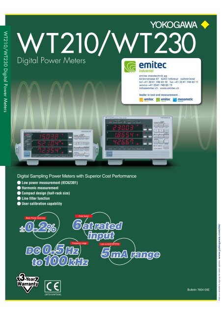
<strong>WT210</strong>/<strong>WT230</strong> <strong>Digital</strong> <strong>Power</strong> <strong>Meters</strong><br />
<strong>WT210</strong>/<strong>WT230</strong><br />
<strong>Digital</strong> <strong>Power</strong> <strong>Meters</strong><br />
<strong>Digital</strong> Sampling <strong>Power</strong> <strong>Meters</strong> with Superior Cost Performance<br />
� Low power measurement (IEC62301)<br />
� Harmonic measurement<br />
� Compact design (half-rack size)<br />
� Line filter function<br />
� User calibration capability<br />
Basic <strong>Power</strong> Accuracy<br />
±0.2% ±0.2%<br />
(<strong>WT210</strong>/<strong>WT230</strong>)<br />
Crest factor<br />
Frequency range<br />
DC DC 0.5 0.5 Hz Hz<br />
to100 to100 kHz kHz<br />
6 6 at at rated rated<br />
input input<br />
Low current (<strong>WT210</strong>)<br />
5 5 mA mA range range<br />
Bulletin 7604-00E<br />
www.yokogawa.com/tm/<br />
Visit our website to sign up for email updates.
Unser Angebot<br />
<strong>emitec</strong> messte<strong>ch</strong>nik ag<br />
birkenstrasse 47 6343 rotkreuz switzerland<br />
tel +41 (0)41 748 60 10 fax +41 (0)41 748 60 11<br />
info@<strong>emitec</strong>.<strong>ch</strong> www.<strong>emitec</strong>.<strong>ch</strong><br />
Profitieren Sie vom einmaligen Angebot und holen Sie si<strong>ch</strong> das professionelle Package zum Spitzenpreis ins<br />
Labor! (Gültig bis 27.07.2012)<br />
Das Package besteht aus folgenden Teilen:<br />
• Yokogawa <strong>Power</strong>meter <strong>WT210</strong> mit Harmonics Option und RS232- oder GPIB-S<strong>ch</strong>nittstelle<br />
• Yokogawa <strong>Power</strong> Consumption Measuring Software<br />
Das Angebot bes<strong>ch</strong>ränkt si<strong>ch</strong> auf ein Package pro Kunde.<br />
Preisgestaltung des Package (Alle Preise exkl. MwSt. und Versand)<br />
Position Rabattpreis Rabatt Alter Preis<br />
<strong>WT210</strong> Leistungsmessgerät 1‘950.00 CHF 40% 3‘250.00 CHF<br />
S<strong>ch</strong>nittstelle /C1 (GPIB) oder /C2 (RS232) 246.00 CHF 40% 410.00 CHF<br />
Harmonics Option /HRM 407.40 CHF 40% 679.00 CHF<br />
<strong>Power</strong> Consumption Software kostenlos<br />
Total 2603.40 CHF statt 4339.00 CHF<br />
Weitere Optionen<br />
External Shunt Input /EX1 163.20 CHF 40% 272.00 CHF<br />
External Shunt Input /EX2 163.20 CHF 40% 272.00 CHF<br />
4 Channel D/A Output /DA4 325.80 CHF 40% 543.00 CHF<br />
Comparator and D/A /CMP 407.40 CHF 40% 679.00 CHF<br />
Interessiert? Nehmen Sie mit uns Kontakt auf!<br />
info@<strong>emitec</strong>.<strong>ch</strong> / 041 748 60 10<br />
Mindestkonfiguration<br />
Optional
2<br />
The <strong>WT230</strong>’s advanced specifications and its wide range of functions let you handle all your measurement applications from low-frequency<br />
equipment to three phase equipments using a single power meter.<br />
One unit also handles standby low-power measurements and rated-power measurements (functions available with the <strong>WT210</strong> only).<br />
<strong>WT230</strong> <strong>WT210</strong><br />
● A Wide Frequency Range Lets You Work on a Variety of Different Applications<br />
LEDs<br />
0.2%<br />
Now you can obtain more precise<br />
measurements on DC driven equipment su<strong>ch</strong><br />
as LEDs.<br />
● Accuracy Is Assured between 1% and 130%<br />
1% input<br />
751552<br />
● Capture a Variety of Signal Types<br />
Surge current and maximum load state<br />
MAX hold function for voltage, current, and power 3<br />
This function lets you keep, on the display, voltage and current peak<br />
values, voltage and current rms values, and maximum values for active<br />
power, apparent power, and reactive power.<br />
Half-wave Rectification, Intermittent Control, Distortion Waves<br />
Measurement of DC components<br />
In addition to using DC inputs, you can obtain precise measurements of<br />
signals containing DC components, su<strong>ch</strong> as intermittent signals and halfwave<br />
rectification signals.<br />
Low-frequency Equipment Commercial <strong>Power</strong> Supplies<br />
Low-frequency measurements starting at 0.5 Hz<br />
0.1%<br />
Low-frequency measurements starting at 0.5 <strong>Power</strong> accuracy is even better than in former WT<br />
Hz can be used with evaluations of<br />
cycloconverter and when a motor are started.<br />
series.<br />
1: Maximum display is 140% of the rated input.<br />
2: Conditions apply to accuracy from 110% to 130%.<br />
With 751552 ➞ Max. 1000 Arms<br />
Instead of taking notes, you can use the internal memory to store and recall<br />
settings and field measurement data.<br />
Functions and Features of the <strong>WT210</strong> and <strong>WT230</strong><br />
130% input<br />
26A 12<br />
Constantly <strong>ch</strong>anging signals<br />
Quick response with display updating as fast as every 0.1 second<br />
With measurement intervals as short as 0.1 second, you can capture<br />
transient phenomena with a fine level of detail. You can also reduce the<br />
time per measurement for increased through put in production testing.<br />
Noisy Signals<br />
Line filter function (fc = 500 Hz)<br />
This function lets you measure fundamental wave rms values for inverter<br />
output voltages.<br />
Information on the features and functions of Yokogawa's <strong>WT210</strong>, <strong>WT230</strong>, accessories, and related products is also available at our web site. http://www.yokogawa.com/tm/<br />
Fr ee<br />
Soft ware<br />
WTViewer for the <strong>WT210</strong>/<strong>WT230</strong><br />
Easily Acquire and Manage <strong>Power</strong><br />
Measurement Data from Your PC<br />
<strong>Power</strong> Consumption<br />
Measurement<br />
Software for IEC62301<br />
● <strong>Power</strong>ful Tools for Energy Measurement<br />
Extended Energy Measurement Applications<br />
Maximum integration time: 10,000 hours 3<br />
Battery equipment applications<br />
Integrating power measurement by polarity<br />
Intermittent Control Equipment Applications<br />
Average active power display 3<br />
● Wide range of 5 mA to 20 A<br />
The built-in 5 mA range lets you measure currents as low as 25 µA. This makes it possible to measure very<br />
low currents on su<strong>ch</strong> things as intermittent control equipment. The wide current range (5 mA to 20 A) means a<br />
single power meter can be used for applications su<strong>ch</strong> as Energy Star® measuremnts, to measure everything<br />
from standby-power to rated-power.<br />
● Applications for a Variety of Add-on Options<br />
Large-current Measurement Using Current Clamps<br />
External input for current sensor<br />
Select either 50/100/200 mV or 2.5/5/10 V.<br />
A current clamp lets you measure currents<br />
without needing to disconnect the power supply<br />
circuit wiring.<br />
Recording to a Recorder<br />
D/A output<br />
Clamp<br />
probe<br />
This option lets you output a variety of measurement<br />
data, su<strong>ch</strong> as voltage, current, and power measurements,<br />
with ±5 V rating, for recording on a recorder. The recorder<br />
can then be used to <strong>ch</strong>eck <strong>ch</strong>anges in data over time.<br />
Online <strong>Power</strong> Meter Control and Recording<br />
GP-IB/serial (RS-232-C) interface<br />
This option lets you control the power<br />
meter through a PC, or save data to a<br />
PC.<br />
External<br />
input<br />
GP-IB/serial interface (RS-232-C)<br />
D/A output<br />
ScopeCorder<br />
Comparator output<br />
The specifications in facing pages are for crest factor 3 setting. See page 5 for the specifications of crest factor 6 setting.<br />
● Measurement According to<br />
Ea<strong>ch</strong> Standard<br />
New<br />
For Requirements for IEC and Other Standards<br />
Crest factor (CF) = 6 mode<br />
This mode allows easy measurement using instruments for whi<strong>ch</strong><br />
crest factors (CF) of 5 and above are required, as is so with most<br />
standards including IEC62018.<br />
<strong>Power</strong> Supply Harmonic Measurements<br />
Calculate voltage, current, reactive power,<br />
content ratio, and phase angle relative to<br />
fundamental frequency for up to 50 orders. This<br />
option is well-suited to power supply environment<br />
evaluations. Measurement time is approximately<br />
90% shorter than in former models.<br />
GO/NO-GO Evaluations on Testing Lines<br />
4-<strong>ch</strong>annel comparator function<br />
A 4-<strong>ch</strong>annel relay contact output (normal-open and normal-close pair) lets<br />
you do GO/NO-GO evaluations on production and testing lines.<br />
3: Popular functions on the WT200 were incorporated into <strong>WT210</strong> and <strong>WT230</strong>.<br />
3
4<br />
Basic Characteristics (for crest factor 3)<br />
Example of Frequency-power Accuracy Characteristics<br />
Tolerance (% of range)<br />
Surge current value (Arms)<br />
10<br />
5<br />
0<br />
-5<br />
<strong>WT230</strong> 15 V/1 A range<br />
Spec and reference values<br />
-10<br />
0.1 1 10 100 1000 10000 100000<br />
350<br />
300<br />
250<br />
200<br />
150<br />
100<br />
50<br />
Frequency (Hz)<br />
5 mA-20 mA range<br />
0.5 A-20 A range<br />
0<br />
0.01 0.1 1 10 100<br />
Input current time width (seconds)<br />
Example of <strong>WT210</strong> Current Accuracy<br />
WT200/WT130 <strong>WT210</strong>/<strong>WT230</strong><br />
Voltage input terminal Binding post Plug-in terminal (safety terminal)<br />
External input terminal Plug-in terminal (safety terminal) BNC<br />
Voltage and current<br />
basic accuracy<br />
0.25% of rng 0.2% of rng<br />
<strong>Power</strong> basic accuracy 0.3% of rng (WT200)<br />
0.35% of rng (WT130)<br />
0.2% of rng<br />
Frequency range DC, 10 Hz to 20 kHz DC, 0.5 Hz to 100 kHz<br />
Assured accuracy range 10% to 130% of range rating 1% to 130% of range rating<br />
Display updating interval 0.25 second (fixed) 0.1/0.25/0.5/1/2/5 seconds<br />
V, A, W display digits 4 digits (WT130)<br />
5 digits (WT200)<br />
5 digits<br />
Line filter function No Yes (fc = 500 Hz)<br />
Frequency filter function Yes (fc = 300 Hz) Yes (fc = 500 Hz)<br />
Key lock No Yes<br />
Harmonic measurement display<br />
updating interval<br />
Approximately 3 seconds 0.25/0.5/1/2/5 seconds<br />
Remote signals when EXT HOLD and EXT TRIG are added. EXT START, All six signals listed to the left are added.<br />
comparator is installed EXT STOP, EXT RESET, and INTEG BUSY are not added. Pin assign is <strong>ch</strong>anged.<br />
Online data format ASCII ASCII, binary<br />
Waveform data communications output No Yes (need /HRM)<br />
Addressable mode B for<br />
GP-IB communications<br />
Yes No<br />
Display digits (factory default) 4 digits 5 digits<br />
Online output data digits (factory default) 4 digits 5 digits<br />
Functions Included with the WT200 (but Not Included with the WT130) and Included with the <strong>WT210</strong>/<strong>WT230</strong><br />
• MAX hold function • Moving decimal point display based on integrated power value<br />
• 10,000-hour maximum integration time • Integration with few data omissions • Average active power display<br />
<strong>WT230</strong> <strong>WT210</strong><br />
Indicated value tolerance (% of reading)<br />
10<br />
8<br />
6<br />
4<br />
2<br />
0<br />
-2<br />
-4<br />
-6<br />
-8<br />
100 mA range: 60 Hz input<br />
-10<br />
0.1 1 10 100<br />
Input level relative to set range (% of range)<br />
Current Input Surge Withstanding Ability Example of Influence of Common Mode Voltage<br />
Tolerance (% of range)<br />
5<br />
4<br />
3<br />
2<br />
1<br />
0<br />
<strong>WT230</strong> 150 V range<br />
<strong>WT230</strong> 500 mA range<br />
Spec and reference values<br />
-1<br />
0.1 1 10 100 1000 10000 100000<br />
Frequency (Hz)<br />
Example of D/A Output Response Comparison with Former Models<br />
display update time
Specifications<br />
The latest product information is available at our web site http://www.yokogawa.com/tm/. Review the specifications to determine whi<strong>ch</strong> model is right for you.<br />
Input Specifications<br />
Input type<br />
Rated values<br />
(ranges)<br />
Measuring instrument loss<br />
(input resistance)<br />
Parameter Voltage<br />
Maximum instantaneous allowed input<br />
(1 cycle, 20 ms duration)<br />
Maximum instantaneous allowed input<br />
(1 second duration)<br />
Maximum continuous allowed input<br />
Maximum continuous common mode voltage<br />
(with 50/60 Hz input)<br />
Common mode rejection ratio (CMRR)<br />
600 Vrms across input terminal and case<br />
Note: The Maximum Range in the equation is 600 V,<br />
20 A, 10 V(EX1), or 200 mV(EX2).<br />
Input terminal type<br />
Crest factor 3<br />
Crest factor 6<br />
Resistance voltage divider<br />
15/30/60/150/300/600 V<br />
Input resistance: Approximately 2 MΩ<br />
Input capacitance: Approximately 13 pF<br />
Peak voltage of 2.8 kV or rms value of 2.0 kV (whi<strong>ch</strong>ever is less)<br />
Maximum instantaneous allowed input<br />
(1 second duration)<br />
Peak voltage of 2.0 kV or rms value of 1.5 kV (whi<strong>ch</strong>ever is less)<br />
Floating input<br />
Current<br />
Shunt input system<br />
Direct input: 5/10/20/50/100/200 mA (<strong>WT210</strong> only) 1<br />
; 0.5/1/2/5/10/20 A (<strong>WT210</strong>/<strong>WT230</strong>)<br />
External input (optional): 2.5/5/10 V(EX1) or 50/100/200 mV(EX2)<br />
7.5/15/30/75/150/300 V Direct input: 2.5/5/10/25/50/100mA (<strong>WT210</strong> only) 1<br />
; 0.25/0.5/1/2.5/5/10 A (<strong>WT210</strong>/<strong>WT230</strong>)<br />
External input (optional): 1.25/2.5/5 V(EX1) or 25/50/100 mV(EX2)<br />
Direct input: Approximately 500 mΩ + approximately 0.1 µH (5-200 mA 3 ; <strong>WT210</strong>)<br />
Approximately 6 mΩ + 10 mΩ (max)2 + approximately 0.1 µH (0.5-20 A 4 ; <strong>WT210</strong>)<br />
Approximately 6 mΩ approximately 0.1 µH (0.5-20 A; <strong>WT230</strong>)<br />
External input: Approximately 100 kΩ (EX1:2.5/5/10 V 5 ), approximately 20 kΩ (EX2:50/100/200 mV 6 )<br />
0.5-20 A 4 (<strong>WT210</strong>/<strong>WT230</strong>): Peak current of 450 A or rms value of 300 A (whi<strong>ch</strong>ever is less)<br />
5-200 mA 3 (<strong>WT210</strong>): Peak current of 150 A or rms value of 100 A (whi<strong>ch</strong>ever is less)<br />
External input: Peak value of 10 times range or less<br />
0.5-20 A 4 (<strong>WT210</strong>/<strong>WT230</strong>): Peak current of 150 A or rms value of 40 A (whi<strong>ch</strong>ever is less)<br />
5-200 mA 3 (<strong>WT210</strong>): Peak current of 30 A or rms value of 20 A (whi<strong>ch</strong>ever is less)<br />
External input: Peak value of 10 times range or less<br />
0.5-20 A 4 (<strong>WT210</strong>/<strong>WT230</strong>): Peak current of 100 A or rms value of 30 A (whi<strong>ch</strong>ever is less)<br />
5-200 mA 3 (<strong>WT210</strong>): Peak current of 30 A or rms value of 20 A (whi<strong>ch</strong>ever is less)<br />
External input: Peak value of 5 times range or less<br />
600 Vrms (with output connector protective cover), CAT II / 400 Vrms (without output connector protective cover) CAT II<br />
50/60 Hz, -80 dB or higher (±0.01% of range or less) with voltage input terminals shorted and current input terminals open and external input terminals shorted<br />
Reference value (up to 100 kHz): ±((Maximum range rating)/(Range rating) × 0.001 × f% of rng) or less (voltage range and 0.5-20 A current range and external<br />
input range 7 )<br />
±((Maximum range rating)/(Range rating) × 0.0002 × f% of rng) or less (<strong>WT210</strong>; 5-200 mA range)<br />
Note: 0.01% or higher. f is in kHz. 7 Decuple the above-formula about the external input range.<br />
Plug-in terminal (safety terminal) Direct input: Large binding post<br />
External input: BNC connector (insulation type)<br />
A/D converter Simultaneous conversion of voltage and current inputs<br />
Resolution: 16 bits<br />
Maximum conversion speed: Approximately 20 µs (approximately 51 kHz)<br />
Range swit<strong>ch</strong>ing<br />
Ranges can be set manually, automatically, or through online controls.<br />
Auto-range function<br />
Range raising: When a measurement exceeds 130% of the rating, or when the peak value exceeds approximately 300% 8 of the rating<br />
Range lowering: When a measurement falls to 30% or less of the rating, and the peak value falls to approximately 300% 8 or less of the rating for the low range<br />
8, Approximately 600% for crest factor 6<br />
Measurement mode swit<strong>ch</strong>ing Any of the following, selected manually or through online controls: RMS (true rms value measurements for both voltage and current), V MEAN (calibration of<br />
average-value-rectified rms value for voltage; true rms value measurement for current), DC (simple averages for both voltage and current)<br />
Note: Current direct input and external sensor input cannot both be used at the same time. When you operate current input terminals and external input terminals, please be careful.<br />
Since these terminals are electrically connected inside the instrument.<br />
1, Connect wires that mat<strong>ch</strong> the size of the measurement current. 2, Factory setting 3, 2.5 -100 mA for crest factor 6<br />
4, 0.25-10 A for crest factor 6 5, 1.25/2.5/5 V for crest factor 6 6, 25/50/100 mV for crest factor 6<br />
Measurement Functions<br />
Parameter Voltage/current<br />
System<br />
Frequency range<br />
Crest factor<br />
Accuracy (three months after calibration)<br />
(Conditions)<br />
Temperature: 23±5°C<br />
Humidity: 30-75% RH<br />
Input waveform: Sinewave<br />
<strong>Power</strong> factor: cosj = 1<br />
common mode voltage: 0 V DC<br />
Frequency filter: ON at 200 Hz or less<br />
Scaling: OFF<br />
Display digits: 5 digits<br />
After CAL is executed<br />
Crest factor 3<br />
Note: In the accuracy calculation formula, f is in kHz.<br />
<strong>Power</strong> factor effect<br />
Note: In the accuracy calculation formula, f is in kHz.<br />
Effective input range (Crest factor 3)<br />
Accuracy (12 months after calibration)<br />
Line filter function<br />
Accuracy with line filter on<br />
Temperature coefficient<br />
Display updating intervals<br />
DC:<br />
0.5 Hz ≤ f < 45 Hz:<br />
45 Hz ≤ f ≤ 66 Hz:<br />
66 Hz < f ≤ 1 kHz:<br />
1 kHz < f ≤ 10 kHz:<br />
10 kHz < f ≤ 100 kHz:<br />
* Add ±10 µA to the current DC accuracy.<br />
±(0.2% or rdg + 0.2% of rng)*<br />
±(0.1% of rdg + 0.2% of rng)<br />
±(0.1% of rdg + 0.1% of rng)<br />
±(0.1% of rdg + 0.2% of rng)<br />
±((0.07 × f)% of rdg + 0.3% of rng)<br />
±((0.5% of rdg + 0.5% of rng)<br />
±((0.04 × (f-10))% of rdg)<br />
<strong>Digital</strong> sampling; sum of averages method<br />
DC, and 0.5 Hz to 100 kHz<br />
3 or 6 (with rated input) 300 (with minimum effective input)<br />
DC:<br />
0.5 Hz ≤ f < 45 Hz:<br />
45 Hz ≤ f ≤ 66 Hz:<br />
66 Hz < f ≤ 1 kHz:<br />
1 kHz < f ≤ 10 kHz:<br />
10 kHz < f ≤ 100 kHz:<br />
Active power<br />
±(0.3% or rdg + 0.2% of rng)*<br />
±(0.3% of rdg + 0.2% of rng)<br />
±(0.1% of rdg + 0.1% of rng)<br />
±(0.2% of rdg + 0.2% of rng)<br />
±(0.1% of rdg + 0.3% of rng)<br />
±((0.067 × (f-1))% of rdg)<br />
±(0.5% of rdg + 0.5% of rng)<br />
±((0.09 × (f-10))% of rdg)<br />
* Add ±10 µA × voltage reading to the power DC accuracy.<br />
For cosϕ = 0<br />
45 Hz ≤ f ≤ 66 Hz: ±0.2% of VA (VA is a reading value of apparent power)<br />
Reference data (up to 100 kHz): ±((0.2 + 0.2 × f)% of VA)<br />
Indicated value tolerance for 0 < cosϕ < 1<br />
Add (tanj ϕ (effect when cosj = 0)% of power reading to the above power accuracy.<br />
Note: ϕ is the phase angle between voltage and current.<br />
19 -130% of voltage/current range rating (for accuracy at 110-130%, add the reading tolerance × 0.5 to the above accuracy)<br />
Add the accuracy's reading tolerance (three months after calibration) × 0.5 to the accuracy three months after calibration.<br />
A low-pass filter can be inserted in the input circuit for measurement. The cutoff frequency (fc) is 500 Hz.<br />
Voltage and current: Add 0.2% of rdg at 45-66 Hz. Add 0.5% of rdg below 45 Hz.<br />
<strong>Power</strong>: Add 0.3% of rdg at 45-66 Hz, Add 1% of rdg below 45 Hz.<br />
Accuracy (for crest factor 6) Double the accuracy's range tolerance of the accuracy for crest factor 3.<br />
±0.03% of range/°C at 5-18°C and 28-40°C.<br />
0.1/0.25/0.5/1/2/5 seconds<br />
Lead/lag is detected correctly when phase angle equal to or greater than ±5° with both voltage and current inputs as sine waves equal to or greater than 50%<br />
rng: Range rdg: Reading 9, 2 for crest factor 6<br />
10<br />
Lead/lag detecting<br />
(Crest factor 3)<br />
of rated range-value, and the frequency is between 20 Hz to 2 kHz. 10, 100% for crest factor 6<br />
Measurement lower limit frequency Data updating rate 0.1 second 0.25 second 0.5 second 1 second 2 seconds 5 seconds<br />
Measurement lower limit frequency 25 Hz 10 Hz 5 Hz 2.5 Hz 1.5 Hz 0.5 Hz<br />
Frequency Measurements<br />
Measurement inputs: V1, V2, V3, A1, A2, or A3 (select one)<br />
Measurement system: Reciprocal system<br />
Measurement frequency ranges<br />
100 ms: 25 Hz ≤ f ≤ 100 kHz<br />
250 ms: 10 Hz ≤ f ≤ 100 kHz<br />
500 ms: 5 Hz ≤ f ≤ 100 kHz<br />
1 sec: 2.5 Hz ≤ f ≤ 100 kHz<br />
2.5 sec: 1.5 Hz ≤ f ≤ 50 kHz<br />
5 sec: 0.5 Hz ≤ f ≤ 20 kHz<br />
Accuracy (1 year): ±(0.06% of rdg)<br />
Conditions: Input equal to at least 30% 11 of voltage/current rated range.<br />
Frequency filter function ON at 200 Hz and below.<br />
11, 60% for crest factor 6<br />
Frequency filter cutoff frequency: 500 Hz<br />
Communication Functions (Optional for the <strong>WT210</strong>)<br />
GP-IB or serial interface (RS-232-C) (select one)<br />
GP-IB<br />
Electrical and me<strong>ch</strong>anical specifications:<br />
Conform to IEEE Standard 488-1978 (JIS C1901-1987).<br />
Functional specifications:<br />
SH1, AH1, T5, L4, SR1, RL1, PR0, DC1, DT1, C0<br />
Protocol: Conforms to IEEE Standard 488.2-1992.<br />
Code used: ISO (ASCII) code<br />
Addresses: 0-30 talker/listener addresses can be set.<br />
Serial interface (RS-232-C)<br />
Transmission mode: Asyn<strong>ch</strong>ronous<br />
Baud rates: 1200, 2400, 4800, 9600 bps<br />
5
6<br />
Specifications<br />
Calculation Functions Internal Memory Functions<br />
Measurement data<br />
Singlephase3wire<br />
Three-phase 3-wire<br />
(2 voltages,<br />
2 currents)<br />
Three-phase 3-wire<br />
(3 voltages,<br />
3 currents)<br />
Threephase4wire<br />
2 3<br />
3 3<br />
Voltage ∑V (V1 + V3)/2<br />
(V1 + V2 + V3)/3<br />
Current ∑A<br />
(A1 + A3)/2<br />
(A1 + A2 + A3)/3<br />
Active power ∑W<br />
W1 + W3<br />
W1 + W2 + W3<br />
var1 + var2 + var3<br />
<strong>Power</strong><br />
VA1 + VA2 + VA3<br />
factor PF,<br />
∑PF<br />
Phase<br />
angle deg,<br />
∑deg<br />
degi =<br />
cos -1 Reactive<br />
power<br />
var, ∑var<br />
Apparent<br />
vari = (VA<br />
power<br />
VA, ∑VA<br />
(Wi/VAi)<br />
2 - W 2 )<br />
VAi = Vi × Ai<br />
Pfi = Wi/VAi ∑W/∑VA<br />
cos -1 var1 + var3<br />
VA1 + VA3 (VA1 + VA3) (VA1 + VA2 + VA3)<br />
(∑W/∑VA)<br />
Notes<br />
1. This equipment's apparent power (VA), reactive power (var), power factor (PF),<br />
and phase angle (deg) are calculated from voltage, current, and active power.<br />
(Therefore, if the input contains a distorted wave, the values may not mat<strong>ch</strong> those<br />
of other measuring instruments based on different measurement principles.)<br />
2. If either voltage or current falls to 0.5%(for crest factor 3. 1.0% for crest factor 6) of<br />
the range rating or less, then the apparent power (VA) and reactive power (var) are<br />
displayed as zero, and errors are displayed for power factor (PF) and phase angle<br />
(deg).<br />
3. The sign of the var of ea<strong>ch</strong> phase is displayed with +(positive). In the ∑var<br />
calculation, the var value for ea<strong>ch</strong> phase is calculated with a negative sign if the<br />
current input leads the voltage input, and with a positive sign if the current input<br />
lags the voltage input. Then the value of ∑ var may be displayed with –(negative).<br />
4. Apparent power (VA) and reactive power (var) cannot be calculated and displayed<br />
at the harmonics measurement mode.<br />
Display Functions<br />
Display unit: 7-segment LED (light-emitting diode)<br />
Display areas: 3<br />
Display area<br />
A<br />
B<br />
C<br />
Displayed information<br />
V, A, W, VA, var (for ea<strong>ch</strong> element), integration elapsed time<br />
V, A, W, PF, deg (for ea<strong>ch</strong> element, percentage (content percentage, THD)<br />
V, A, W, V/AHz, Vpk, Apk, ±Wh, ±Ah (for ea<strong>ch</strong> element), MATH<br />
Measurement parameters Maximum display Display resolution<br />
V, A, W, VA, var 99999<br />
0.001%<br />
PF<br />
±1.0000<br />
0.01%<br />
deg<br />
±180.0<br />
0.1*<br />
±Wh, ±Ah<br />
999999<br />
0.0001%<br />
VHz, AHz<br />
99999 Input frequency/20,000<br />
Display digits: 4 or 5 digits (selectable by user).<br />
Factory default setting is 5 digits.<br />
Units: m, k, M, V, A, W, VA, var, Hz, h±, deg, %<br />
Display updating intervals: 0.1/0.25/0.5/1/2/5 seconds<br />
Response time: Maximum 2 times the display updating interval (time required<br />
for display value to enter accuracy range of final value with line<br />
filter off, when range rating abruptly <strong>ch</strong>anges from 0% to 100%,<br />
and from 100% to 0%)<br />
Maximum display: 140% of voltage/current range rating<br />
Minimum display: About Vrms, Arms, Vmean and Ah<br />
0.5% of range rating (for crest factor 3)<br />
1% of range rating (for crest factor 6)<br />
Less than 0.5% is zero suppression.<br />
Display scaling function<br />
Effective digits: Selected automatically according to the digits in the voltage and<br />
current ranges.<br />
Setting range: 0.001 to 9999<br />
Averaging function<br />
Methods: Exponential average or moving average<br />
Exponential average: Attenuation constant of 8, 16, 32, or 64<br />
Moving average: Number of averages set to 8, 16, 32, or 64<br />
Auto-range monitor<br />
An LED turns on when the input value is outside the range set for the auto-range.<br />
MAX hold function<br />
This function can be used to hold V, A, W, VA, var, Vpk, and Apk at maximum values.<br />
MATH functions<br />
System: When a function key on DISPLAY C is pressed to select the<br />
MATH functions, it is possible to perform efficiency (<strong>WT230</strong> only)<br />
and input crest factor measurements, as well as arithmetic<br />
calculations on DISPLAY A and B measurements. In addition, it<br />
is possible to display average active power for time-converted<br />
integrated power.<br />
Integration Functions<br />
Display resolution: The minimum display resolution <strong>ch</strong>anges together with the<br />
integrated value.<br />
Maximum display: -99999 to 999999 MWh/MAh<br />
Modes: Standard integration mode (timer mode), continuous integration<br />
mode (repeat mode), manual integration mode<br />
Timer: Automatic integration start/stop based on timer setting.<br />
Setting range: 000 h:00 min:00 sec to 10000 h:00 min:00 sec<br />
(If the time is set to zero, manual mode is automatically set.)<br />
Count over flow: When the integrated value exceeds 999999 MWh/MAh or falls<br />
to at least -99999 MWh/MAh, the elapsed time is saved and the<br />
operation is stopped.<br />
Accuracy: ±(display accuracy + 0.1% of rdg)<br />
Timer accuracy: ±0.02%<br />
Remote control: Starting, stopping, and resetting can be controlled through<br />
external contact signals. This function is only available when<br />
option /DA4, /DA12 or /CMP is installed.<br />
Stored data Normal measurement Harmonic measurement<br />
<strong>WT210</strong> (760401) Data for 600 samples Data for 30 samples<br />
<strong>WT230</strong> (760502) Data for 300 samples Data for 30 samples<br />
<strong>WT230</strong> (760503) Data for 200 samples Data for 30 samples<br />
Store interval: Display updating interval and 1 second to 99 hours, 59 minutes,<br />
and 59 seconds<br />
Recall interval: Display updating interval and 1 second to 99 hours, 59 minutes,<br />
and 59 seconds<br />
(Both can be set in 1-second increments.)<br />
Panel setting information: Four different patterns of panel setting information can be written/<br />
read.<br />
Harmonic Measurement Function (/HRM Option)<br />
System: PLL syn<strong>ch</strong>ronization<br />
Measurement frequency range:<br />
Fundamental frequency in range of 40-440 Hz<br />
Maximum display: 99999<br />
Display digits: 4 or 5 digits (selectable by user).<br />
Factory default setting is 5 digits.<br />
Measurement parameters: V, A, W, deg (<strong>WT210</strong>), V1, V2, V3, A1, A2, A3, W1, W2,<br />
W3, deg1, deg2, deg3 (<strong>WT230</strong>), individual harmonic levels, rms<br />
voltage, rms current, active power, fundamental frequency PF,<br />
harmonic distortion rate, individual harmonic content<br />
Measurement element: These parameters can only be measured simultaneously for<br />
a single specified input element.<br />
Sampling speed, window width, and analysis orders<br />
The values for these parameters vary according to the input fundamental frequency<br />
as shown below.<br />
Fundamental frequency Sampling speed Window width Analysis orders<br />
40 ≤ f < 70 Hz f × 512 Hz 2 periods of f 50<br />
70 ≤ f < 130 Hz f × 256 Hz 4 periods of f 50<br />
130 ≤ f < 250 Hz f × 128 Hz 8 periods of f 50<br />
250 ≤ f ≤ 440 Hz f × 64 Hz 16 periods of f 30<br />
FFT data length: 1024<br />
FFT processed word length: 32 bits<br />
Window function: Rectangular<br />
Display updating interval:<br />
0.25/0.5/1/2/5 seconds Updating is slower during online output<br />
according to the communication speed and the number of<br />
parameters transferred.<br />
Accuracy: Add ±0.2% of range to normal measurement accuracy.<br />
Note: For nth-order component input, add {10/(m+1)} % of<br />
the nth-order reading to the n+mth order and n-mth order.<br />
D/A Output (/DA4 or /DA12 Option)<br />
Output voltage: ±5 V FS (maximum approximately ±7.5 V) for ea<strong>ch</strong> rated value<br />
Number of outputs: 12 parameters with /DA12 option; 4 parameters with /DA4 option<br />
Output data selection: Can be set separately for ea<strong>ch</strong> <strong>ch</strong>annel.<br />
Accuracy: ±(equipment accuracy + 0.2% of FS)(FS=5 V)<br />
D/A converter: 12-bit resolution<br />
Response time: Maximum 2 times the display updating interval<br />
Updating interval: Same as the equipment's display updating interval<br />
Temperature coefficient: ±0.05%˚C of FS<br />
Output type<br />
Frequency<br />
Integration<br />
D/A output<br />
7.0V<br />
5.0V<br />
Other parameters<br />
D/A output<br />
0<br />
7.5V<br />
5.0V<br />
2.5V<br />
Display<br />
140%<br />
100%<br />
0%<br />
-100%<br />
-140%<br />
0.5V<br />
0<br />
0.5Hz 1Hz 10Hz 100Hz 1kHz 10kHz 100kHz Display value<br />
t0: Rated setting time<br />
Output<br />
7.0V<br />
5.0V<br />
0V<br />
-5.0V<br />
-7.0V<br />
Note: For PF and<br />
deg, there is no<br />
output between ±5<br />
and ±7 V. When an<br />
error occurs,<br />
approximately 7.5 V<br />
are output.<br />
For input equal to 140% of rating<br />
-140% -100%<br />
7.5V<br />
7.0V<br />
5.0V<br />
0V<br />
For rated input<br />
D/A output<br />
-5.0V<br />
-7.0V<br />
-7.5V<br />
100% 140%<br />
t0 Integration time<br />
Display value
External Input (/EX1 or EX2 Option)<br />
Select either /EX1 or /EX2 for the voltage output-type current sensor.<br />
/EX1: 2.5/5/10 V<br />
/EX2: 50/100/200 mV<br />
Specifications: See the section on input specifications.<br />
Comparator Output (/CMP Option)<br />
Output method: Normal-open and normal-close relay contact output (pair)<br />
Number of output parameters and settings:<br />
Four parameters; can be set separately on ea<strong>ch</strong> output <strong>ch</strong>annel.<br />
Contact capacitance:24 V/0.5 A<br />
D/A output (4-<strong>ch</strong>annel):See section on D/A output (optional)<br />
External Control Signal (with /DA or /CMP Option Only)<br />
External control signals:EXT-HOLD, EXT-TRIG, EXT-START, EXT-STOP, EXT-RESET,<br />
INTEG-BUSY<br />
Input: TTL level negative pulse<br />
General Specifications<br />
Warmup time: Approximately 30 minutes<br />
Operating temperature and humidity ranges: 5-40˚C, 20-80% RH (no condensation)<br />
Storage temperature: -25-60˚C (no condensation)<br />
Maximum operating elevation: 2000 meters<br />
Insulating resistance: 50 MΩ or higher at 500 V DC across all of the following areas:<br />
Voltage input terminals (ganged) and case<br />
Current input terminals (ganged) and case<br />
Voltage input terminals (ganged) and current input terminals<br />
(ganged)<br />
Voltage input terminals (ganged) of ea<strong>ch</strong> element<br />
Current input terminals (ganged) of ea<strong>ch</strong> element<br />
Voltage input terminals (ganged) and power plug<br />
Current input terminals (ganged) and power plug<br />
Case and power plug<br />
Insulating withstand voltage:<br />
3700 V for one minute at 50/60 Hz across all of the following<br />
areas:<br />
Voltage input terminals (ganged) and case<br />
Current input terminals (ganged) and case<br />
Voltage input terminals (ganged) and current input terminals<br />
(ganged)<br />
Voltage input terminals (ganged) of ea<strong>ch</strong> element<br />
Current input terminals (ganged) of ea<strong>ch</strong> element<br />
Voltage input terminals (ganged) and power plug<br />
Current input terminals (ganged) and power plug<br />
1500 V for one minute at 50/60 Hz across case and power plug<br />
<strong>Power</strong> supply: Free power supply (100-240 V), 50/60 Hz frequency<br />
Consumed power: Max 35 VA for <strong>WT210</strong>, max 55 VA for <strong>WT230</strong><br />
External dimensions for <strong>WT210</strong>:<br />
Approximately 213 × 88 × 379 mm (WHD) (excluding projections)<br />
External dimensions for <strong>WT230</strong>:<br />
Approximately 213 × 132 × 379 mm (WHD) (excluding<br />
projections)<br />
Weight: Approximately 3 kg for <strong>WT210</strong>, approximately 5 kg for <strong>WT230</strong><br />
Safety standard Complying standard EN61010-1<br />
Overvoltage category (Installation category) II<br />
Pollution degree 2<br />
Emission Complying standard EN61326 Class A<br />
EN61000-3-2<br />
EN61000-3-3<br />
AS/NZS 2064 Class A<br />
Immunity Complying standard EN61326 Annex A<br />
■ Exterior View<br />
179<br />
250<br />
213<br />
73 23<br />
88<br />
19<br />
13 213 23 327<br />
34<br />
28.5<br />
■ Wiring Types and Model Numbers<br />
Wiring<br />
132<br />
21<br />
Single-phase 2-wire<br />
Single-phase 3-wire<br />
Three-phase 3-wire (2 voltages, 2 currents)<br />
Three-phase 3-wire (3 voltages, 3 currents)<br />
Three-phase 4-wire<br />
Model<br />
760401<br />
✓<br />
–<br />
–<br />
–<br />
–<br />
359<br />
356<br />
760502<br />
✓<br />
✓<br />
✓<br />
–<br />
–<br />
Unit : mm<br />
<strong>WT210</strong><br />
<strong>WT230</strong><br />
760503<br />
✓<br />
✓<br />
✓<br />
✓<br />
✓<br />
■ Model Numbers and Suffix Codes<br />
Model number Suffix code<br />
Description<br />
760401<br />
<strong>WT210</strong> single-input element model<br />
<strong>Power</strong> cord -D<br />
UL/CSA standard<br />
-F<br />
VDE standard<br />
-R<br />
AS standard<br />
-Q<br />
BS standard<br />
-H<br />
GB standard<br />
Options /C1<br />
GP-IB communication interface<br />
Select one<br />
/C2<br />
Serial (RS-232-C) communication interface<br />
/EX1<br />
External input 2.5/5/10 V<br />
Select one<br />
/EX2<br />
External input 50/100/200 mV<br />
/HRM Harmonic measurement function<br />
/DA4 4-<strong>ch</strong>annel DA output<br />
Select one<br />
/CMP Comparator and D/A, 4 <strong>ch</strong>annels ea<strong>ch</strong><br />
Note: The <strong>WT210</strong> communication interface cannot be <strong>ch</strong>anged or modified after delivery.<br />
Model number Suffix code<br />
Description<br />
760502<br />
760503<br />
Interface -C1<br />
-C2<br />
<strong>Power</strong> cord<br />
Options<br />
-D<br />
-F<br />
-R<br />
-Q<br />
-H<br />
/EX1<br />
/EX2<br />
/HRM<br />
/DA12<br />
/CMP<br />
■ Standard Accessories<br />
■ Rack mounts<br />
<strong>WT230</strong> 2-input element model<br />
<strong>WT230</strong> 3-input element model<br />
GP-IB communication interface<br />
Serial (RS-232-C) communication interface<br />
UL/CSA standard<br />
VDE standard<br />
AS standard<br />
BS standard<br />
GB standard<br />
External input 2.5/5/10 V<br />
External input 50/100/200 mV<br />
Harmonic measurement function<br />
12-<strong>ch</strong>annel DA output<br />
Comparator and D/A, 4 <strong>ch</strong>annels ea<strong>ch</strong><br />
Select one<br />
Select one<br />
Select one<br />
<strong>Power</strong> cord, <strong>Power</strong> fuse, Current input protective cover, Rubber feet for the hind feet,<br />
24-pin connector (provided only on options/DA4, /DA12, and /CMP), User’s manual<br />
When using the <strong>WT210</strong>/<strong>WT230</strong> with WTViewer (for the <strong>WT210</strong>/<strong>WT230</strong>) for waveform<br />
display on the PC screen or harmonic measurement, the /HRM option must be installed<br />
on the <strong>WT210</strong>/<strong>WT230</strong>.<br />
Product<br />
Model or part number<br />
Specification<br />
Order quantity<br />
Rack mounting kit 751533-E2 For <strong>WT210</strong> EIA standalone installation 1<br />
Rack mounting kit 751533-J2 For <strong>WT210</strong> JIS standalone installation 1<br />
Rack mounting kit 751534-E2 For <strong>WT210</strong> EIA connected installation 1<br />
Rack mounting kit 751534-J2 For <strong>WT210</strong> JIS connected installation 1<br />
Rack mounting kit 751533-E3 For <strong>WT230</strong> EIA standalone installation 1<br />
Rack mounting kit 751533-J3 For <strong>WT230</strong> JIS standalone installation 1<br />
Rack mounting kit 751534-E3 For <strong>WT230</strong> EIA connected installation 1<br />
Rack mounting kit 751534-J3 For <strong>WT230</strong> JIS connected installation 1<br />
Ask Yokogawa for information on rack mounts in whi<strong>ch</strong> <strong>WT210</strong> and <strong>WT230</strong> are combined.<br />
■ Accessories (sold separately)<br />
Model number Description<br />
B9317WD 1.5 mm hex wren<strong>ch</strong><br />
B9284LK External sensor cable<br />
Note:Crest Factor<br />
For fastening cable on 758931<br />
For external input; 50 cm<br />
waveform peak<br />
RMS value<br />
The crest factor is the ratio of the waveform<br />
peak value and the RMS value.<br />
waveform peak<br />
Crest factor (CF, peak factor) =<br />
RMS value<br />
About the measurable crest factor of our power measuring instruments, please refer<br />
to the following equation.<br />
{measuring range x CF setting (3 or 6)}<br />
Crest factor (CF) =<br />
measured value (RMS)<br />
*However, the peak value of the measured signal must be less than or equal to the<br />
continuous maximum allowed input.<br />
* The crest factor on a power meter is specified by how many times peak input<br />
value is allowed relative to rated input value. Therefore, even if some measured<br />
signals exist whose crest factors are larger than the specifications of the<br />
instrument (the crest factor standard at the rated input), you can measure signals<br />
having crest factors larger than the specifications by setting a measurement<br />
range that is large relative to the measured signal.<br />
For example, even if you set CF = 3, CF5 or higher measurements are possible if<br />
the measured value (RMS) is 60% or less than the measuring range. Also, for a<br />
setting of CF = 3, measurements of CF = 300 are possible with the minimum<br />
effective input (1% of measuring range).<br />
* Crest factor 6 is supported by the <strong>WT210</strong>/<strong>WT230</strong> of firmware versions 1.11 and<br />
later.<br />
7
Related Products<br />
758917<br />
Measurement leads<br />
Two leads in a set. Use 758917 in<br />
combination with 758922 or 758929.<br />
Total length: 75 cm<br />
Rating: 1000 V, 32 A<br />
758922<br />
Small alligator adapters<br />
For connection to measurement leads<br />
(758917). Two in a set.<br />
Rating: 300 V<br />
■ For Wide range & high precision(0.05% + 30 µA)<br />
CT60/CT200/CT1000 Current Sensors<br />
758929<br />
Large alligator adapters<br />
For connection to measurement leads<br />
(758917). Two in a set.<br />
Rating: 1000 V<br />
Current Sensor Current Transducer Clamp on Probe<br />
● DC~800 kHz/60 Apk, DC~500 kHz/200 Apk, DC~300 kHz/1000 Apk<br />
● Wide dynamic range: ±0-1000 A (DC)/1000 A peak (AC)<br />
● Wide measurement frequency range: DC and up to 800 kHz<br />
● High-precision fundamental accuracy: ±(0.05% of reading + 30 µA)<br />
● ±15 V DC power supply, connector, and load resistor required.<br />
For detailed information, see Current Sensors& Accessories Catalog<br />
Bulletin CT1000-00E.<br />
CT series do not conform to CE Marking.<br />
Free Application Software<br />
WTViewer for the <strong>WT210</strong> and <strong>WT230</strong><br />
Easily Acquire and Manage <strong>Power</strong> Measurement Data form Your PC<br />
758923<br />
Safety terminal adapter set<br />
(spring-hold type) Two adapters in a<br />
set.<br />
■ For high precision (0.05% + 40 µA)<br />
751574 Current Transducer<br />
WTViewer for the <strong>WT210</strong>/<strong>WT230</strong> is a software application that allows you to load numeric<br />
and waveform data measured with the <strong>WT210</strong> or WT 230 <strong>Digital</strong> <strong>Power</strong> Meter to a PC via<br />
GP-IB or serial (RS-232-C) communications.<br />
Visit our web site to register your product and download this software<br />
program.<br />
http://www.yokogawa.com/tm/<strong>WT210</strong>/<br />
See our web site or the software catalog (Bulletin 7604-32E) for detailed specifications.<br />
● Wide measurement frequency range: DC and up to 100 kHz (-3 dB)<br />
● High-precision fundamental accuracy: ±(0.05% of reading + 40 µA)<br />
● Wide dynamic range: 0-600 A (DC)/600 A peak (AC)<br />
● ±15 V DC power supply, connector, and load resistor required.<br />
For detailed information, see <strong>Power</strong> Meter Accessory Catalog Bulletin<br />
7515-52E.<br />
758931<br />
Safety terminal adapter set<br />
Screw-fastened adapters. Two<br />
adapters in a set. 1.5 mm Allen<br />
wren<strong>ch</strong> included for tightening.<br />
B9284LK<br />
External sensor cable<br />
For the external input of the <strong>WT210</strong><br />
and WT 230.<br />
Length: 50 cm<br />
■ For high-current measurements up to 1000 Arms<br />
751552 Clamp on Probe<br />
758917<br />
Measurement leads<br />
758921<br />
Fork Terminal Adapter<br />
● Measurement frequency range: 30 Hz to 5 kHz<br />
● Basic accuracy: 0.3% of reading<br />
● Maximum allowed input: AC 1000 Arms, max 1400 Apk (AC)<br />
● Current output type: 1 mA/A<br />
A separately sold fork terminal adapter set (758921), measurement<br />
leads (758917), etc. are required for connection to <strong>WT210</strong>/<strong>WT230</strong>. For<br />
detailed information, see <strong>Power</strong> Meter Accessory Catalog Bulletin 7515-<br />
52E.<br />
<strong>Power</strong> Consumption<br />
Measurement Software<br />
Meets the requirement of IEC62301, household electrical appliances - Measurement of<br />
Standby <strong>Power</strong><br />
LabVIEW* Driver Software (Free)<br />
* LabVIEW is a registered trademark of National<br />
Instruments Corporation.<br />
Information on the features and functions of Yokogawa’s WT series & PZ, accessories, and related products is also available at our homepage. http://www.yokogawa.com/tm/<br />
Protecting the global environment<br />
Yokogawa's products are developed and produced in facilities that have received<br />
ISO14001 approval.<br />
YOKOGAWA METERS & INSTRUMENTS CORPORATION<br />
Global Sales Dept. /Phone: +81-42-534-1413 Facsimile: +81-42-534-1426<br />
E-mail: tm@cs.jp.yokogawa.com<br />
YOKOGAWA CORPORATION OF AMERICA Phone: (1)-770-253-7000, Fax: (1)-770-254-0928<br />
YOKOGAWA EUROPE B.V. Phone: (31)-88-4641000, Fax: (31)-88-4641111<br />
YOKOGAWA ENGINEERING ASIA PTE. LTD. Phone: (65)-62419933, Fax: (65)-62412606<br />
Due to the nature of this product, it is possible to tou<strong>ch</strong> its metal parts. Therefore, there is a risk of electric shock, so the product must be used with caution.<br />
Download this software program from our web<br />
site.<br />
CAUTION<br />
Read the user's manual carefully for correct and safe use of the<br />
instrument.<br />
Subject to <strong>ch</strong>ange without notice.<br />
[Ed : 04/b] Copyright ©2002<br />
Printed in Japan, 108(KP)