WT210/WT230 Digital Power Meters - emitec-industrial.ch
WT210/WT230 Digital Power Meters - emitec-industrial.ch
WT210/WT230 Digital Power Meters - emitec-industrial.ch

Create successful ePaper yourself
Turn your PDF publications into a flip-book with our unique Google optimized e-Paper software.
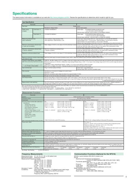
Specifications<br />
The latest product information is available at our web site http://www.yokogawa.com/tm/. Review the specifications to determine whi<strong>ch</strong> model is right for you.<br />
Input Specifications<br />
Input type<br />
Rated values<br />
(ranges)<br />
Measuring instrument loss<br />
(input resistance)<br />
Parameter Voltage<br />
Maximum instantaneous allowed input<br />
(1 cycle, 20 ms duration)<br />
Maximum instantaneous allowed input<br />
(1 second duration)<br />
Maximum continuous allowed input<br />
Maximum continuous common mode voltage<br />
(with 50/60 Hz input)<br />
Common mode rejection ratio (CMRR)<br />
600 Vrms across input terminal and case<br />
Note: The Maximum Range in the equation is 600 V,<br />
20 A, 10 V(EX1), or 200 mV(EX2).<br />
Input terminal type<br />
Crest factor 3<br />
Crest factor 6<br />
Resistance voltage divider<br />
15/30/60/150/300/600 V<br />
Input resistance: Approximately 2 MΩ<br />
Input capacitance: Approximately 13 pF<br />
Peak voltage of 2.8 kV or rms value of 2.0 kV (whi<strong>ch</strong>ever is less)<br />
Maximum instantaneous allowed input<br />
(1 second duration)<br />
Peak voltage of 2.0 kV or rms value of 1.5 kV (whi<strong>ch</strong>ever is less)<br />
Floating input<br />
Current<br />
Shunt input system<br />
Direct input: 5/10/20/50/100/200 mA (<strong>WT210</strong> only) 1<br />
; 0.5/1/2/5/10/20 A (<strong>WT210</strong>/<strong>WT230</strong>)<br />
External input (optional): 2.5/5/10 V(EX1) or 50/100/200 mV(EX2)<br />
7.5/15/30/75/150/300 V Direct input: 2.5/5/10/25/50/100mA (<strong>WT210</strong> only) 1<br />
; 0.25/0.5/1/2.5/5/10 A (<strong>WT210</strong>/<strong>WT230</strong>)<br />
External input (optional): 1.25/2.5/5 V(EX1) or 25/50/100 mV(EX2)<br />
Direct input: Approximately 500 mΩ + approximately 0.1 µH (5-200 mA 3 ; <strong>WT210</strong>)<br />
Approximately 6 mΩ + 10 mΩ (max)2 + approximately 0.1 µH (0.5-20 A 4 ; <strong>WT210</strong>)<br />
Approximately 6 mΩ approximately 0.1 µH (0.5-20 A; <strong>WT230</strong>)<br />
External input: Approximately 100 kΩ (EX1:2.5/5/10 V 5 ), approximately 20 kΩ (EX2:50/100/200 mV 6 )<br />
0.5-20 A 4 (<strong>WT210</strong>/<strong>WT230</strong>): Peak current of 450 A or rms value of 300 A (whi<strong>ch</strong>ever is less)<br />
5-200 mA 3 (<strong>WT210</strong>): Peak current of 150 A or rms value of 100 A (whi<strong>ch</strong>ever is less)<br />
External input: Peak value of 10 times range or less<br />
0.5-20 A 4 (<strong>WT210</strong>/<strong>WT230</strong>): Peak current of 150 A or rms value of 40 A (whi<strong>ch</strong>ever is less)<br />
5-200 mA 3 (<strong>WT210</strong>): Peak current of 30 A or rms value of 20 A (whi<strong>ch</strong>ever is less)<br />
External input: Peak value of 10 times range or less<br />
0.5-20 A 4 (<strong>WT210</strong>/<strong>WT230</strong>): Peak current of 100 A or rms value of 30 A (whi<strong>ch</strong>ever is less)<br />
5-200 mA 3 (<strong>WT210</strong>): Peak current of 30 A or rms value of 20 A (whi<strong>ch</strong>ever is less)<br />
External input: Peak value of 5 times range or less<br />
600 Vrms (with output connector protective cover), CAT II / 400 Vrms (without output connector protective cover) CAT II<br />
50/60 Hz, -80 dB or higher (±0.01% of range or less) with voltage input terminals shorted and current input terminals open and external input terminals shorted<br />
Reference value (up to 100 kHz): ±((Maximum range rating)/(Range rating) × 0.001 × f% of rng) or less (voltage range and 0.5-20 A current range and external<br />
input range 7 )<br />
±((Maximum range rating)/(Range rating) × 0.0002 × f% of rng) or less (<strong>WT210</strong>; 5-200 mA range)<br />
Note: 0.01% or higher. f is in kHz. 7 Decuple the above-formula about the external input range.<br />
Plug-in terminal (safety terminal) Direct input: Large binding post<br />
External input: BNC connector (insulation type)<br />
A/D converter Simultaneous conversion of voltage and current inputs<br />
Resolution: 16 bits<br />
Maximum conversion speed: Approximately 20 µs (approximately 51 kHz)<br />
Range swit<strong>ch</strong>ing<br />
Ranges can be set manually, automatically, or through online controls.<br />
Auto-range function<br />
Range raising: When a measurement exceeds 130% of the rating, or when the peak value exceeds approximately 300% 8 of the rating<br />
Range lowering: When a measurement falls to 30% or less of the rating, and the peak value falls to approximately 300% 8 or less of the rating for the low range<br />
8, Approximately 600% for crest factor 6<br />
Measurement mode swit<strong>ch</strong>ing Any of the following, selected manually or through online controls: RMS (true rms value measurements for both voltage and current), V MEAN (calibration of<br />
average-value-rectified rms value for voltage; true rms value measurement for current), DC (simple averages for both voltage and current)<br />
Note: Current direct input and external sensor input cannot both be used at the same time. When you operate current input terminals and external input terminals, please be careful.<br />
Since these terminals are electrically connected inside the instrument.<br />
1, Connect wires that mat<strong>ch</strong> the size of the measurement current. 2, Factory setting 3, 2.5 -100 mA for crest factor 6<br />
4, 0.25-10 A for crest factor 6 5, 1.25/2.5/5 V for crest factor 6 6, 25/50/100 mV for crest factor 6<br />
Measurement Functions<br />
Parameter Voltage/current<br />
System<br />
Frequency range<br />
Crest factor<br />
Accuracy (three months after calibration)<br />
(Conditions)<br />
Temperature: 23±5°C<br />
Humidity: 30-75% RH<br />
Input waveform: Sinewave<br />
<strong>Power</strong> factor: cosj = 1<br />
common mode voltage: 0 V DC<br />
Frequency filter: ON at 200 Hz or less<br />
Scaling: OFF<br />
Display digits: 5 digits<br />
After CAL is executed<br />
Crest factor 3<br />
Note: In the accuracy calculation formula, f is in kHz.<br />
<strong>Power</strong> factor effect<br />
Note: In the accuracy calculation formula, f is in kHz.<br />
Effective input range (Crest factor 3)<br />
Accuracy (12 months after calibration)<br />
Line filter function<br />
Accuracy with line filter on<br />
Temperature coefficient<br />
Display updating intervals<br />
DC:<br />
0.5 Hz ≤ f < 45 Hz:<br />
45 Hz ≤ f ≤ 66 Hz:<br />
66 Hz < f ≤ 1 kHz:<br />
1 kHz < f ≤ 10 kHz:<br />
10 kHz < f ≤ 100 kHz:<br />
* Add ±10 µA to the current DC accuracy.<br />
±(0.2% or rdg + 0.2% of rng)*<br />
±(0.1% of rdg + 0.2% of rng)<br />
±(0.1% of rdg + 0.1% of rng)<br />
±(0.1% of rdg + 0.2% of rng)<br />
±((0.07 × f)% of rdg + 0.3% of rng)<br />
±((0.5% of rdg + 0.5% of rng)<br />
±((0.04 × (f-10))% of rdg)<br />
<strong>Digital</strong> sampling; sum of averages method<br />
DC, and 0.5 Hz to 100 kHz<br />
3 or 6 (with rated input) 300 (with minimum effective input)<br />
DC:<br />
0.5 Hz ≤ f < 45 Hz:<br />
45 Hz ≤ f ≤ 66 Hz:<br />
66 Hz < f ≤ 1 kHz:<br />
1 kHz < f ≤ 10 kHz:<br />
10 kHz < f ≤ 100 kHz:<br />
Active power<br />
±(0.3% or rdg + 0.2% of rng)*<br />
±(0.3% of rdg + 0.2% of rng)<br />
±(0.1% of rdg + 0.1% of rng)<br />
±(0.2% of rdg + 0.2% of rng)<br />
±(0.1% of rdg + 0.3% of rng)<br />
±((0.067 × (f-1))% of rdg)<br />
±(0.5% of rdg + 0.5% of rng)<br />
±((0.09 × (f-10))% of rdg)<br />
* Add ±10 µA × voltage reading to the power DC accuracy.<br />
For cosϕ = 0<br />
45 Hz ≤ f ≤ 66 Hz: ±0.2% of VA (VA is a reading value of apparent power)<br />
Reference data (up to 100 kHz): ±((0.2 + 0.2 × f)% of VA)<br />
Indicated value tolerance for 0 < cosϕ < 1<br />
Add (tanj ϕ (effect when cosj = 0)% of power reading to the above power accuracy.<br />
Note: ϕ is the phase angle between voltage and current.<br />
19 -130% of voltage/current range rating (for accuracy at 110-130%, add the reading tolerance × 0.5 to the above accuracy)<br />
Add the accuracy's reading tolerance (three months after calibration) × 0.5 to the accuracy three months after calibration.<br />
A low-pass filter can be inserted in the input circuit for measurement. The cutoff frequency (fc) is 500 Hz.<br />
Voltage and current: Add 0.2% of rdg at 45-66 Hz. Add 0.5% of rdg below 45 Hz.<br />
<strong>Power</strong>: Add 0.3% of rdg at 45-66 Hz, Add 1% of rdg below 45 Hz.<br />
Accuracy (for crest factor 6) Double the accuracy's range tolerance of the accuracy for crest factor 3.<br />
±0.03% of range/°C at 5-18°C and 28-40°C.<br />
0.1/0.25/0.5/1/2/5 seconds<br />
Lead/lag is detected correctly when phase angle equal to or greater than ±5° with both voltage and current inputs as sine waves equal to or greater than 50%<br />
rng: Range rdg: Reading 9, 2 for crest factor 6<br />
10<br />
Lead/lag detecting<br />
(Crest factor 3)<br />
of rated range-value, and the frequency is between 20 Hz to 2 kHz. 10, 100% for crest factor 6<br />
Measurement lower limit frequency Data updating rate 0.1 second 0.25 second 0.5 second 1 second 2 seconds 5 seconds<br />
Measurement lower limit frequency 25 Hz 10 Hz 5 Hz 2.5 Hz 1.5 Hz 0.5 Hz<br />
Frequency Measurements<br />
Measurement inputs: V1, V2, V3, A1, A2, or A3 (select one)<br />
Measurement system: Reciprocal system<br />
Measurement frequency ranges<br />
100 ms: 25 Hz ≤ f ≤ 100 kHz<br />
250 ms: 10 Hz ≤ f ≤ 100 kHz<br />
500 ms: 5 Hz ≤ f ≤ 100 kHz<br />
1 sec: 2.5 Hz ≤ f ≤ 100 kHz<br />
2.5 sec: 1.5 Hz ≤ f ≤ 50 kHz<br />
5 sec: 0.5 Hz ≤ f ≤ 20 kHz<br />
Accuracy (1 year): ±(0.06% of rdg)<br />
Conditions: Input equal to at least 30% 11 of voltage/current rated range.<br />
Frequency filter function ON at 200 Hz and below.<br />
11, 60% for crest factor 6<br />
Frequency filter cutoff frequency: 500 Hz<br />
Communication Functions (Optional for the <strong>WT210</strong>)<br />
GP-IB or serial interface (RS-232-C) (select one)<br />
GP-IB<br />
Electrical and me<strong>ch</strong>anical specifications:<br />
Conform to IEEE Standard 488-1978 (JIS C1901-1987).<br />
Functional specifications:<br />
SH1, AH1, T5, L4, SR1, RL1, PR0, DC1, DT1, C0<br />
Protocol: Conforms to IEEE Standard 488.2-1992.<br />
Code used: ISO (ASCII) code<br />
Addresses: 0-30 talker/listener addresses can be set.<br />
Serial interface (RS-232-C)<br />
Transmission mode: Asyn<strong>ch</strong>ronous<br />
Baud rates: 1200, 2400, 4800, 9600 bps<br />
5